Enterprise Service Automation 1.0 Quick Start Guide
Available Languages
Contents
- Quick Start Guide
- Overview
- About This Guide
- Product Overview
- Key Features
- Before You Install
- Understanding System Requirements
- Supporting Platforms and Functions
- Ports Used by Enterprise Service Automation
- Integrating with APIC-EM and Cisco Prime Infrastructure
- Pre-requisites
- Before You Begin Installation
- Installing Cisco Enterprise Service Automation
- Logging in to the Enterprise Service Automation
- Managing Certificates
- CLI commands
Quick Start Guide
Overview
This section provides basic information about the product and this Guide.
About This Guide
This guide describes the licensing and ordering details, system requirements, steps to install Cisco Enterprise Service Automation and other reference documents.
Product Overview
Cisco Enterprise Service Automation (ESA) is an orchestration and management application that allows enterprise IT operation teams to design, provision, and manage virtual and physical branch networks. IT operators can choose a predefined service catalog from the ESA Graphical User Interface (GUI) and map it to a physical network location where services are to be deployed. They can then use ESA to monitor branch devices and provide feedback to customers on QoS, capacity, other recommendations to enhance enterprise branch network efficiency and utilization.
ESA is not a standalone application. It operates collaboratively with Cisco Prime Infrastructure and Cisco Application Policy Infrastructure Controller Enterprise Module (APIC-EM) to provision and deploy the configuration and services on the enterprise network infrastructure.
Key Features
For an overview of Enterprise Service Automation features and benefits, see Cisco Enterprise Service Automation Data Sheet.
Before You Install
This section describes the system requirements and the tasks to be completed before installing Cisco Enterprise Service Automation.
Understanding System Requirements
Enterprise Service Automation is distributed as an ISO image. You can install the ISO image as a guest Virtual Machine (VM) on one of the following VMware ESXi versions:
The following table provides product specifications for the various virtual appliance deployment options supported by Cisco Enterprise Service Automation.
Supporting Platforms and Functions
For supporting platforms and functions, see Cisco Enterprise Service Automation Data Sheet.
Ports Used by Enterprise Service Automation
The following table lists the ports used by Enterprise Service Automation. These ports must be open in firewalls to use these services.
Integrating with APIC-EM and Cisco Prime Infrastructure
Cisco Enterprise Service Automation is a process tool that supports Application Programming Interfaces (APIs) that allows external systems to plug in to the tool and automates the provisioning of branches that align with the organizational processes. ESA is a thin, lightweight orchestration layer that closely integrates with other Cisco management tools and controllers such as Cisco Prime Infrastructure and APIC-EM and is offered as an enterprise-packaged solution. ESA uses the services available by the controller and management tools to do plug and play, registration and provisioning of both physical and virtual branches. It helps to monitor and manage the components provisioned for inventory, change, fault, and performance functions.
For ESA 1.0 to function, APIC-EM 1.4.1 and Prime Infrastructure 3.1.6 needs to be installed. For more information on the installation guidelines, see the below links:
For APIC-EM 1.4.1 version, see http://www.cisco.com/c/en/us/td/docs/cloud-systems-management/application-policy-infrastructure-controller-enterprise-module/1-4-x/install_1-4-1-x/b_apic_em_install_guide_v_1-4-1-x.html.
For Prime Infrastructure 3.1.6 version, see http://www.cisco.com/c/en/us/td/docs/net_mgmt/prime/infrastructure/3-1-6/release/notes/cpi_rn.html.
Pre-requisites
During ESA installation, you can choose to automatically add Prime Infrastructure and APIC-EM to ESA and enable JMS broker in Prime Infrastructure.
The following are the prerequisites:
APIC-EM and Prime Infrastructure should be up and reachable by ESA.
Note
While installing Enterprise Service Automation, NBI user is also referred as API user. For details, see step 8 in Installing Cisco Enterprise Service Automation.
- xmpBroker password should be enabled in Prime Infrastructure. To get xmpBroker password, follow these steps:
Login to Prime Infrastructure CLI as admin.
Enable the JMS port in the firewall via CLI: ncs run jms enable.
Set the JMS broker password via the PI CLI: ncs pnp-secret. Make sure to note down the password.
If required, you can change the JMS credentials later.
Check the Enable Change Audit Notification checkbox in Administration > Settings > System Settings in Prime Infrastructure.
Reboot Prime Infrastructure server.
Note
After logging into ESA application, enter xmpBroker as ESA Broker User Name while you add Prime Infrastructure to ESA. The password is generated from Prime Infrastructure. For more details on adding Prime Infrastructure to ESA, see Logging in to the Enterprise Service Automation.
Before You Begin Installation
ProcedureBefore installing ESA on a virtual machine, you must ensure that VMware ESXi is installed and configured on the machine that you plan to use as the ESA server.
To create virtual machine on VMware vSphere environment, follow these steps:
Step 1 In the VMware vSphere client, right-click the deployed Virtual Appliance in the left pane, and choose New Virtual Machine. A Create New Virtual Machine wizard appears. Step 2 Choose any one of the following configuration options: Step 3 Click Next to proceed. Step 4 Enter a Name for the new Virtual Machine and click Next. Step 5 Select a destination location for storing all the VM files and click Next. Step 6 Click Linux radio button in Guest Operating System and choose either CentOS 4/5/6/7(64-bit) or RHEL 7.1(64-bit) from the Version drop-down list. Step 7 Click Next to proceed. Step 8 To create Network Connections, choose the number of Network Interface Card(s) from the drop-down list and choose the NIC 1 Network. Step 9 Click Next to proceed. Step 10 Enter the Virtual Disk Size and Provisioning Policy, and click Next. See Understanding System Requirements Step 11 Check Edit the virtual machine settings before completion and click Continue. Step 12 Enter CPU and Memory Settings of the Virtual Machine and then click Finish.See Understanding System Requirements Step 13 To activate the virtual machine, right-click the created Virtual Machine and choose Power > Power On.
Installing Cisco Enterprise Service Automation
Procedure
Step 1 Download the ESA ISO image. Save the image file in any location accessible by your host. For example:
Note For better performance, place the ESA ISO file on the host computer hard drive. However, if you want the file to be available to multiple users, you can place it on a network share drive (Windows) or exported file system (Linux).
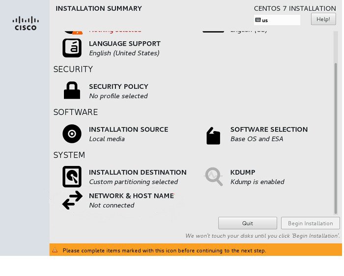
Step 2 In the VMware vSphere client, click CD/DVD drive and select the appropriate Installer disk image file (ISO) and navigate to the location where you downloaded and saved the ESA ISO file. Step 3 Right-click the virtual machine and click Open Console and press Enter. Step 4 In the console, press Enter and choose Install Enterprise Service Automation to run the Installer Setup. The Virtual Machine boots up and the Installation Summary wizard appears.
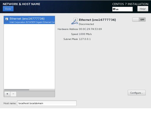
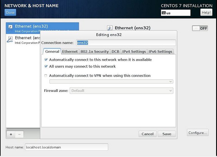
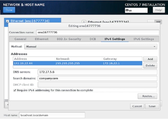
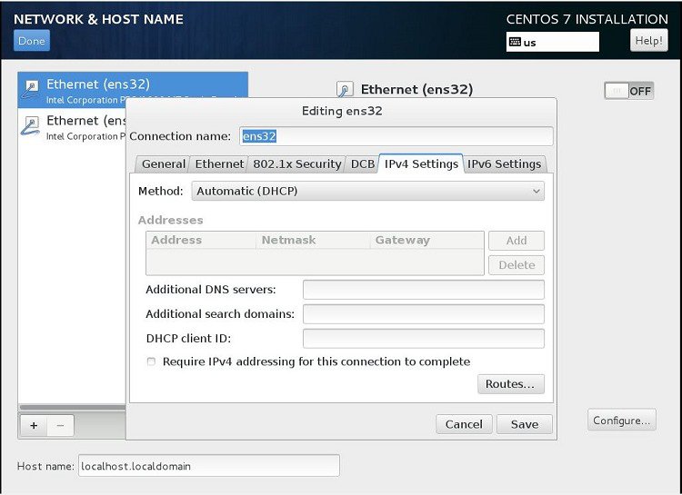
Step 5 Click the Network & Host Name in the Installation Summary wizard to configure the network interface. Step 6 Click Configure. The Network and Hostname configuration wizard appears. Step 7 In the General tab, check Automatically connect to this network when it is available check box and click Save. Step 8 In the IPV4 Settings tab, do any one of the following:
From the Method drop-down list, choose Manual and click Add. Enter the IP Address configuration details and click Save.
From the Method drop-down list, choose Automatic (DHCP) Method, and click Save.
When two interfaces are configured with IP addresses and routes during installation, the second interface IP and routes are missing when the installation is complete. So, for the second interface configuration, you can manually configure and/or modify the missing routes using Centos system tool ‘nmtui '.
To configure the missing routes using nmtui tool, perform the following steps:
In the root access of the ESA server, enter nmtui . The Network Manager TUI window appears on the screen.
Choose Edit a Connection from the list of options and click <ok>.
Select the appropriate Ethernet Interface and click <Edit...>.
Enter the following details for the selected Interface: IPV4 Address, Gateway, DNS servers, Search domains, routing.
Note If the routes are defined, click <Add...> to add the routes by entering following details: Destination Address/Prefix, Next Hop, Metric and click <OK>. If this network is not preferred for default routes, select Never use this network for default route.
If required, select Require IPV4 addressing for this connection.
Click <OK>.
Click <Quit> to go to root access of ESA server.
Enter nmtui to go to the Network Manager TUI window.
Choose Activate a Connection and click <OK>.
Select the appropriate interface and click <Activate>.
To view the Interface configuration details, enter ifconfig in the root access of ESA Server.
Note ESA application does not support the management of IPV6 devices. However, the installation of ESA does.
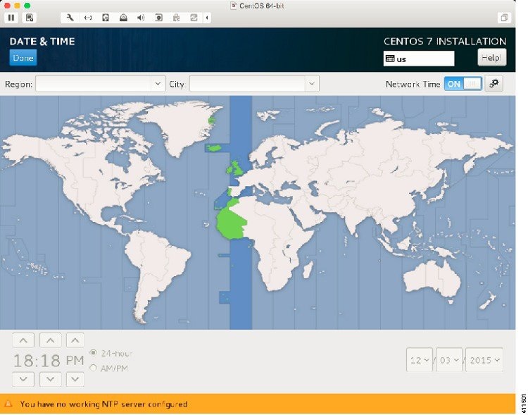
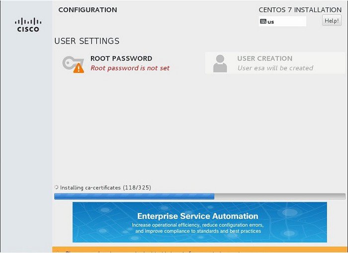
Step 9 Enter the Host name, set the network interface to ON, and click Done. Step 10 Click Date &Time in the Installation Summary wizard to setup NTP server correctly. Step 11 In the Date and Time wizard, select the Region in the map, turn ON the Network Time and click Done. Step 12 Click Begin Installation. Step 13 Click Root Password under User Settings for system administration. Step 14 Enter the Root Password, Confirm Password, and click Done. After few minutes, the system reboots and a command prompt appears.
Step 15 To complete the final system configuration, follow these steps in the command prompt:
Login as 'esa' with default password 'esa123'.
The docker images will be automatically installed.
Note SSH access is disabled for root. However, the esa user can use ‘su‐’ with the root password. For improved security, use SSH private and public keys. See the CentOS wiki page for more information.
Note For improved security, it is recommended that you do not use default password. Next time, when you login as ‘esa’, enter the new password.
Enter a username for ESA web user interface administrator and press Enter. By default, the username is admin.
Enter a password and confirm password for ESA web user interface administrator and press Enter.
Enter the email address for ESA web user interface administrator and press Enter.
(optional) Enter the backup password and confirm password to encrypt the backup data.
Note You can use the default password generated from the system or create your own password.
Enter the Fully Qualified Domain Name for the ESA instance in the following format: hostname.domainname.
To set up connections to APIC-EM and Prime Infrastructure, choose either of the following:
To configure APIC-EM and Prime Infrastructure later, enter N. ESA installation will complete. Later, you should login to ESA and provide APIC-EM and Prime Infrastructure details from the user interface. For details, see Logging in to the Enterprise Service Automation.
Also, you should enable JMS in Prime Infrastructure. For details, see Pre-requisites section in Integrating with APIC-EM and Cisco Prime Infrastructure.
To configure APIC-EM and Prime Infrastructure now, enter Y and follow these steps:
Enter the IP Address or hostname of the APIC-EM.
Enter a valid API administrator user name for APIC-EM.
Enter administrator password and confirm password for APIC-EM.
Enter the IP Address or hostname of the Prime Infrastructure.
Enter a valid API root user name for Prime Infrastructure.
Enter root password and confirm password for Prime Infrastructure.
Enter a JMS secret key (password) and confirm password to setup a JMS connection to Prime Infrastructure. You can use the default password generated from the system or create your own password.
Enter a valid CLI administrator username for Prime Infrastructure.
Enter administrator password and confirm password for Prime Infrastructure.
Now, the system will login to Prime Infrastructure CLI and set up JMS. This process requires Prime Infrastructure server to restart and it takes more than 20 minutes. Once done, the Enterprise Service Automation application will start up.
Now, Enterprise Service Automation is successfully installed.
Logging in to the Enterprise Service Automation
ProcedureFollow these steps to log in to the Enterprise Service Automation user interface through a web browser:
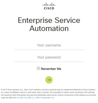
Step 1 Launch one of the Supported Browsers. Step 2 Navigate to https://ipaddress, where ipaddress is the IP address of the virtual machine on which you installed the ISO image. The application login screen will appear in the browser window. Step 3 Enter the Username and Password.
Note You should use the username and password given during the ESA installation (See Step Step 15 in the Installing Cisco Enterprise Service Automation section).
Step 4 Click Login. Initial System Setup wizard appears (where you can configure the global parameters). Step 5 Click Next. Step 6 (Optional) To ensure system security, check appropriate Password Policy rules and click Next. Step 7 To change the default login credentials, enter the required information in the Administrator Credentials page, and then click Next. Step 8 (Optional) To configure an SMTP Server for approval notifications and status alerts, enter the required information, and then click Next. Step 9 (Optional) To configure the approval workflow when defining branch profiles, choose the required options in the Workflow Configuration page. Step 10 Click Next. Step 11 (Optional) To display customized notifications on the login page, enter the Login disclaimer and click Next. Step 12 (Optional) To add a Prime Infrastructure external system for configuring and monitoring the network, enter the following connection details:
Name—User-defined name for the server.
User Name—This is the Prime Infrastructure communication username.
Password—This is the Prime Infrastructure communication password.
Protocol—Https protocol for secure communication.
Host—IP address of the server.
Port—Port number of the server.
Broker User Name—This xmpbroker is a static name from Prime Infrastructure. The default username is xmpBroker. See Pre-requisites.
Broker Password—The xmpbroker password that is generated from Prime Infrastructure through JMS. See Pre-requisites.
Step 13 Click Next. Step 14 (Optional) To add an APIC-EM external system for configuring and monitoring the network, enter the following connection details: Step 15 Click Next.
Note It is recommended to add the external controllers during Initial System Setup or you must add those controllers under System Configuration after logging into the ESA application before provisioning.
Step 16 Once the initial system configuration is completed, click Finish. You will be logged out. Login again with your new Username and Password. The home page appears.
Note To exit the user interface, close the browser page or click Logout in the top-right corner of the page. Exiting a ESA user interface session does not shut down ESA on the server until it is set to power-off by the system administrator.
Managing Certificates
ProcedureTo run the Enterprise Service Automation application, you need signed SSL certificates for secured data transmission. Certificates can be self-signed by the server that presents it or can be digitally signed by a third-party recognized certificate authority(CA) that your system already trusts. When you launch the ESA application, a self-signed SSL certificate gets validated and is pre-installed into the system. When external systems, such as APIC-EM and Prime Infrastructure, are added to ESA application, self-signed certificates from those systems are automatically downloaded and added to the system. You can also manually add third-party signed certificate, in case of new certificate request or expiry of the certificate. Third-party signed certificate issued by CA is automatically trusted in web browsers and assures that you have been verified by a trusted third-party.
Note
Make sure that the right certificates are installed into the system and that validation is enabled for security. It is not recommended to bypass certificate validation.
To add a third-party signed certificate, follow these steps:
CLI commands
Login to the ESA Server via SSH to access the Bash shell. The following table shows the list of shell commands for performing backup, restore, application update, application reinstall, viewing system status.
Table 3 Shell Commands Command
Description
esa-status
Displays the status of the high level system components.
esa-logs
Displays the logs to console.(similar to tail -f). Cntl-C to exit.
esa-reset
Re-installs the application without re-initializing database.
esa-dbreset
Re-installs the application and re-initializes database.
esa-install-update
Installs an update from a supplied patch file.
esa-backup
Backup the database. The result will be added to the /opt/backups/db directory.
Output:
[esa@localhost ~]$esa-backup
Backing up...
Backup succeeded: /esa/backups/2016-01-05-08-58UTC.gzip.enc
esa-restore
Restores the contents of a backup created with the esa-backup command.
Output:
[esa@localhost ~]$esa-restore
Usage: esa-restore <password> <file>
Copyright © 2017, Cisco Systems, Inc. All rights reserved.

 Feedback
Contact Cisco
- Open a Support Case

- (Requires a Cisco Service Contract)