Using the MIB
Available Languages
Table Of Contents
Access Using the Nodal Community String
End-to-End Connection Related Tables
Circuit Emulation Endpoint Table
Traps Defined in the Service MIB
Community String Access to the Service MIB
End-to-End Connection Provisioning Interface
General Process Model for Fault Management
Using the MIB
This chapter describes the organization and contents of the Cisco WAN Manager (CWM) Service Agent Management Information Base (MIB). The Service Agent MIB is structured as three separate MIBs:
•
The Network MIB contains the database and network configuration information and the BPX 8600, MGX 8220, MGX 8230, MGX 8250, MGX 8850 (PXM1), and IGX 8400 (both router and feeder nodes) trap definitions. This MIB is supported by the RtmProxy.
•
•
To fully understand the information in this chapter, users must have a working knowledge of SNMP MIB conventions and standards.
MIB Organization
The CWM Service Agent Network and Service MIBs are organized sets of objects, each of which contains information regarding the BPX 8600, MGX 8850, MGX 8250, MGX 8230,
MGX 8220, and IGX 8400 network and services.The SNMP community string is treated differently on these MIBs. The string is used for authentication in the Service MIB, and used as part of the instance in the Network MIB. The community string for identifying a node is the Domain Node (for example, Network1.node3) in the Network MIB's Node and Trunk Tables, and is not used for the RTM MIB.
Each object is assigned a unique identifier within the MIB. Objects are accessed by the SNMP Manager GET and GETNext commands that specify the unique identifier of the object. The Service Agent obtains the value of the specified object and transmits it to the SNMP Manager.
In the Network MIB, all objects are read-only. In the Service MIB, most tables are read-write.
When a single piece of information contained in a single object is required, a simple GET of that object by the SNMP Manager retrieves the information. To obtain more complex information about the network, it requires the retrieval of several objects and the interpretation of their values. This is the case when the SNMP Manager needs to construct and display the network topology.
Network MIB Overview
The Network MIB provides several interfaces, including the fault management related mechanisms and read-only configuration information for network resources. The configuration views presented by the Network MIB are primarily on a per-node basis. In this proxying role, the Service Agent provides a single point of contact to multiple instances of the same MIBs, each representing the configuration of resources for a specific node.

Note
Fault Management Tables
The Network MIB supports fault management and must be utilized in collecting SNMP traps from the network. This section describes the fault management tables that are contained in the Network MIB.
Trap Configuration Table
The Trap Configuration table (trapConfigTable) is used for registering to receive SNMP traps from the Service Agent.
Trap Upload Table
The Trap Upload table (trapUploadTable) is used to retrieve missing traps through the Robust Trap Mechanism (RTM).
Note
Configuration Tables
The Network MIB contains read-only configuration information pertaining to the network, nodes, trunks, circuit lines, Frame Relay ports, and connections in the network. This section describes the configuration tables that are contained in the Network MIB.
Trunk Table
The Trunk table (svTrunkTable) contains trunk-related configuration information for the specified node. Some examples of trunk information include specified slots for certain cards, trunk line load, local and remote line numbers, and the remote node ID (CWM node ID). This read-only table is indexed by slot and physical port number.
Circuit Line Table
The Circuit Line table (lineTable) contains read-only configuration information about the specified IPX circuit lines and is indexed by circuit line number and port number. This table is supported only for IPX card types: CDP, CIP, FRP, and TXR.
Node Table
The Node table (svNodeTable) contains the list of nodes in the network(s) managed and monitored by the CWM associated with this Service Agent. Feeder elements, such as the IGX feeding into a BPX 8600 routing node, are not represented in this table.
Network Table
The Network table (svNetworkTable) contains the list of all networks managed and monitored by the associated CWM. The table is indexed by network name and contains the CWM ID assigned to the network as well as the IPX network ID.
Note
Node-Related Objects
The Network MIB defines a set of objects belonging to the svNodeGroup group. These objects specify certain characteristics of the node, such as the node's alarm state, platform type (that is,
BPX 8600, MGX 8850, MGX 8250, MGX 8230, MGX 8220, or IGX 8400), and ForeSight increase rate. These objects are briefly described in the following subsection on nodal community string access, and can be found in the Network MIB specification.Access Using the Nodal Community String
The configuration tables described above, with the exception of the Node Table and Network Table, provide information on a per-node basis, and require nodal community strings to access the proper instance of the table. The community strings, in essence, index these tables.
Other objects defined in the Network MIB also require nodal community string access, such as the svNodeGrpAlarmState object, which specifies the node alarm status (clear, minor, major, or unreachable). The general format of the community strings for these tables and objects is shown in Table 2-1.
For example, access to the Trunk Table for a node called "node34" in a network called "network1", requires the community string "network1.node34" to be used in an SNMP request.
Service MIB Overview
The Service MIB provides extensive provisioning services for end-to-end connection. In Release 11 of CWM, end-to-end connections between any interface cards supporting Frame Relay (FR), ATM, and Circuit Emulation (CE) combinations are supported. This includes the following:
•
•
•
•
•
•
•
•
•
The Service MIB also contains port provisioning services. Through the SNMP tables, ports can be configured on MGX 8850 Release 1, MGX 8250, MGX 8230, and MGX 8220 shelves and on
IGX 8400 platforms. Configurable port parameters include: port speed, signaling protocol, DE threshold, etc. The following subsections describe the types of services available through Service MIB tables and objects.
Note
End-to-End Connection Related Tables
The Service MIB includes several tables to facilitate the provisioning of end-to-end connections via SNMP. End-to-end connections are specified by two endpoints, local and remote.
From an SNMP perspective connections are composed of MIB objects representing the endpoints and a connection object that links or describes the relationship between the local and remote endpoints. The Connection Tables provide the capability to establish connections, modify parameters associated with the connections, and perform diagnostics on the connections. The following tables provide this information.
Connection Table
This table gives information all about end-to-end connections in the network managed by the associated Cisco CWM workstation and provides capabilities for creating, modifying, testing, and deleting connections. This table is indexed by a connection index, which is a unique positive value generated by the Service Agent during connection creation. The value of 0 is specified during the creation of new connections.
Frame Relay Endpoint Table
This table gives connection characteristic information about all Frame Relay endpoints of every Virtual Connection (VC) in the network. This information includes: QIR, CIR, MIR, PIR, VC queue size, and percent utilization. This table is indexed by node name, shelf name, slot number, physical line number, physical port number, and DLCI.
For a description of the Frame Relay Endpoint Table objects, see the Frame Relay Endpoint Table section in "Accessing the Network and Service MIBs".
Frame Relay Endpoint Attribute Object IDentifier Structure
The Object IDentifier (OID) used for specifying attributes in the Frame Relay endpoint table consists of the ASN.1 identifier associated with the object, followed by the indices into the SNMP table. This allows creation of endpoints to be controlled via a single MIB object, frEndPointRowStatus. Specification of this object includes the name of the endpoint being created, and results in a specified action upon that object. The indices in CWM Release 9.2 are physical in nature, and include the node name, shelf name, slot number, physical line number, port number, and DLCI. For currently available IGX 8400 cards, the endpoints typically specify a 0 value line number.
Specification of the node and shelf names in the OID is accomplished by using a simple encoding/translation from strings to integers. The ASN.1 representation for strings is comprised of the string length followed by the ASCII integer representation for each individual character. Thus the "AXIS245" string would be encoded as: 7.65.88.73.83.50.52.53, where 7 represents the number of characters in the string, 65 represents the character "A", and so on.
Thus, specification of the frEndPointRowStatus object for a Frame Relay endpoint with DLCI 200, located on slot 6, line 2, and port 1 of an MGX 8220 shelf called "AXIS245" connected to a BPX 8600 called "nmsbpx03" appears as follows (shown on multiple lines):
Frame Relay Endpoint MIB Objects
The user can create an endpoint by specifying a single MIB object, if the default endpoint parameters are acceptable. For details about this table, see the Frame Relay Endpoint Table section in Chapter 3.
ATM Endpoint Table
This table gives connection characteristic information about all ATM endpoints in the network, including the middle segments associated with a Frame Relay Network Interworking connection. In a tiered-network architecture, end-to-end connections are comprised of up to three segments: the local feeder element to the local routing node, local routing node to remote routing node, and remote routing node to remote feeder element. Frame Relay connections spanning an ATM core network result in the creation of ATM endpoints in this table. This table also includes the ATM endpoints associated with Frame Relay/ATM Service Interworking connections between FRSM and ASI cards. This table is indexed by node name, shelf name, slot number, physical port number, VPI, and VCI.
For a description of the ATM Endpoint Table object, see the ATM Endpoint Table section in "Accessing the Network and Service MIBs".
ATM Endpoint Attribute OID Structure
The OID used for specifying attributes in the ATM endpoint table consists of the ASN.1 identifier associated with the object, followed by the indices into the SNMP table. This allows creation of endpoints to be controlled via a single MIB object, atmEndPointRowStatus. Specification of this object includes the name of the endpoint being created, and results in a specified action upon that object. The indices in Release 11 of CWM include the node name, shelf name, slot number, physical port number, and VPI/VCI.
Specification of the node and shelf names in the OID is accomplished by using a simple encoding/translation from strings to integers. The ASN.1 representation for strings is comprised of the string length followed by the ASCII integer representation for each individual character. Thus the "AXIS245" string would be encoded as: 7.65.88.73.83.50.52.53, where 7 represents the number of characters in the string, 65 represents the character "A", and so on.
Thus, specification of the atmEndPointRowStatus object for an ATM endpoint with VPI 200 and
VCI 20, located on slot 6, port 1 of an MGX 8220 shelf called "AXIS245" connected to a BPX 8600 called "nmsbpx03" appears as follows (shown on multiple lines):
ATM Endpoint MIB Objects
Creation of an endpoint can be accomplished via the specification of a single MIB object, if the default endpoint parameters are acceptable. For details about this table, see the ATM Endpoint Table section in Chapter 3.
Circuit Emulation Endpoint Table
This table lists the Circuit Emulation (CE) endpoints. Each connection endpoint describes the particular characteristics of the endpoint.
For a description of the CE Endpoint table objects, see the Circuit Emulation Endpoint Table section in "Accessing the Network and Service MIBs".
Connection Group Error Table
This table is used to troubleshoot failed SNMP Set requests during the connection configuration or provisioning process. Based on the SNMP PDU request ID associated with the Set request, a Manager process can locate the specific error relating to the failed request. Examples of reported errors include port not found, endpoint already exists, and invalid bandwidth parameters.
For a description of the Connection Group errors, see the following the sections in "Accessing the Network and Service MIBs":
•
Traps Defined in the Service MIB
The Service MIB defines trap types associated with the operational state of end-to-end connections. These end-to-end traps are generated by CWM when a service fault affecting the network is received. Each trap provides information about the local and remote endpoints affected, the connection status, the connection A-bit status, and the connection type. The trap types defined are
•
•
•
•
•
•
Community String Access to the Service MIB
The community strings used for accessing the Service MIB are stored in the /usr/users/svplus/config/snmpd.cnf configuration file. The community strings control access to the tables and are read during startup, and cannot be dynamically changed during runtime. The default values are
•
•
End-to-End Connection Provisioning Interface
Creating a connection via the Service Agent interface is achievable via a single SNMP Set request. The connection paradigm supported in Release 11 of CWM requires interaction with two types of tables:
•
•
The following basic steps used when creating connections via the Service MIB are briefly outlined:
Step 1
This process involves creation of the ports and specification of characteristics including signaling, port speed, and timer values. For Frame Relay/ATM Service Interworking connections between FRSM and ASI endpoints, the ATM port cannot be provisioned through the CWM Release 9.2 Service Agent interface. ATM and Frame Relay ports are supported in CWM Release 9.2.
Step 2
The endpoint definitions include several parameters associated with bandwidth, queueing, and traffic metrics. For Frame Relay/ATM Service Interworking, the remote endpoint of the connection must be defined in the endpoint table reserved for ATM endpoints.
Step 3
The simple model for connection provisioning allows for connection creation using a single SNMP Set request on multiple MIB objects. When the ports terminating the connections already exist, the following minimum set of MIB objects in Table 2-2 are required to create a connection:
Connection Table
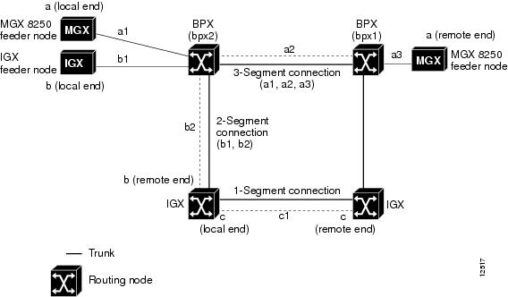
This table maintains characteristic information about all Frame Relay and ATM endpoints of every VC in the network. The entries in this table describe the association between a local and a remote endpoint. These two endpoints define the end-to-end connection, regardless of the network topology. In a tiered network, where feeder elements (for example, MGX 8220 shelves) are connected to a routing mesh network, an end-to-end connection comprises at most, three segments.
Figure 2-1 shows the constituent segments of user connections in different scenarios involving routing nodes and feeder nodes. The boundary between segments is marked with white circles. The "a_local-to-a_remote" connection comprises three segments, while the "b_local-to-b_remote" connection is comprises two segments, and the "c_local-to-c_remote" connection comprises one segment. In a flat network with no feeder elements, each end-to-end connection consists of a single segment.
Figure 2-1 Connection Management Example
The parameters and attributes associated with an entry in the Connection Table typically relate to routing, and are independent of the types of endpoints. Each connection in the table is indexed by an integer determined by the Service Agent when the connection is created. A connection operational status object indicates the connection's state. Other connection objects include a hop-by-hop route description, a ForeSight enable/disable object, and string descriptions of the endpoints.
The remote and local endpoints defining the connection are referenced in the Connection Table by the OID of the first attribute of the endpoint in their respective endpoint tables. In Release 11 of CWM, when provisioning a connection, the local and remote endpoints can be Frame Relay or ATM endpoint. The "incomplete" operational status for an entry in the Connection Table indicates that segments exist, but others are unknown or nonexistent.
Connection Provisioning
For an example of how to provision a connection using SNMP, consider the creation of a Frame Relay end-to-end connection from an IGX node to an MGX 8220 shelf. The local endpoint is located on a node named "nmsigx10" which has a channelized FRM card in slot 6, and a provisioned 128kbps port on DS-0 timeslot 1. The desired DLCI for this endpoint is 150.
For the remote endpoint, consider a Frame Relay endpoint located on an MGX 8220 shelf named "AXIS245" feeding into a BPX 8600 node named "nmsbpx03." The endpoint is located on an FRSM card in slot 6 of the MGX 8220 shelf, on a preprovisioned 128kbps port on physical line 1, DS-0 timeslot 2. The desired DLCI for this endpoint is 200.
Each endpoint is customized with specific parameters defined for the traffic travelling in each direction. The provisioned connection has a high class of service (a high priority for rerouting—on a scale of 0-15, this connection will be assigned a value of 1). In the local-to-remote direction, traffic is provisioned with an MIR of 2400bps, CIR of 3600bps, PIR of 9200bps, and QIR of 4000bps. In the remote-to-local direction, the asymmetric traffic will be provisioned with an MIR of 2300bps, CIR of 3200bps, PIR of 5600bps, and QIR of 3200bps.
The MIB objects described in Table 2-3 must be set in the SNMP request.
Port Provisioning Interface
The port provisioning interface is described in this section. For a description of the Frame Relay Port Table objects, see the Frame Relay Endpoint Table section in Chapter 3.
Port Attribute OID Structure
The OID used for specifying attributes in the Frame Relay Port Table (svFrPortTable) consists of the ASN.1 identifier associated with the object, followed by the indices into the table. This allows creation of ports to be controlled via a single MIB object: svFrPortRowStatus. Specification of this object includes the name of the port being created, and results in a specified action upon that object. The indices in Release 11 of CWM are physical in nature, and include the node name, shelf name, slot number, physical line number, and port number. For currently available IGX 8400 cards, the endpoints typically specify a 0 value line number and a null value for the shelf name.
Specification of the node and shelf names in the OID is accomplished by using a simple encoding/translation from strings to integers. The ASN.1 representation for strings is comprised of the string length followed by the ASCII integer representation for each individual character. Thus the "AXIS245" string would be encoded as: 7.65.88.73.83.50.52.53, where 7 represents the number of characters in the string, 65 represents the character "A", and so on.
Thus, specification of the svFrPortRowStatus object for a Frame Relay FRSM port, located in slot 6, line 2, and DS-0 timeslot 4 of an MGX 8220 shelf called "AXIS245" connected to a BPX 8600 called "nmsbpx03" appears as follows (shown on multiple lines):
Similarly, for an FRM port located in slot 4 and DS-0 timeslot 16 of an IGX node called "nmsigx10", the specification of the svFrPortRowStatus object would appear as follows (shown on multiple lines):
1.3.6.1.4.1.351.1.101.2.4.1.5.
8.110.109.115.105.112.120.49.48.
0.
4.0.16
// ASN.1 ID of svFrPortRowStatus
// ASN.1 representation of "nmsigx10"
// ASN.1 representation of no shelf
// slot.line.port
Port MIB Objects
Creation of a port can be accomplished via the specification of a single MIB object, if the default port parameters are acceptable. For a description of the Frame Relay port objects, see the Frame Relay Endpoint Table section in Chapter 3.
Fault Management Interface
In Release 11 of CWM fault management by external OSSs is based on robust SNMP traps. This trap mechanism, known as Robust Trap Mechanism (RTM), is supported by the SNMP Service Agent running in conjunction with a CWM management system. Through the Service Agent, up to 16 external SNMP Managers (with one reserved for CWM) can register to receive network and service related traps.
In CWM Release 11 some network resources utilize SNMP traps to relay fault information up to CWM, while others utilize proprietary robust alarms and string events. Robust alarms, in Cisco terms, refer to the state representations of network resources at a specific time. String or textual events refer to descriptive events triggered by certain activities and are sent up to the management system.
The two fault management mechanisms have no correlation. Actions occurring in the network, such as resource failures, might result in the generation of textual events as well as a change in alarm status.
Other actions might result in no alarm status; however, they generate a textual event. Furthermore, the order in which robust alarms are received might not reflect the chronological sequence of network events; robust alarms reflect state changes at time <x>. These issues must be considered when constructing Managers that receive these faults.
The primary interface for fault management is through SNMP traps emitted by the SNMP Service Agent. This agent provides a uniform interface that partially hides the hybrid fault management interfaces supported by the various network elements. Managers that register to receive traps from the SNMP Service Agent can receive trap representations of robust alarm status changes as well as textual events. Managers also receive, through the Service Agent, traps from network elements supporting native traps. Therefore, the complete fault management interface presented to users of the Service Agent includes:
•
•
•
•
The differences and usage of these traps is discussed in the following subsections.
Severity Levels
Severity levels in Release 11 of CWM classify the type of textual event received from the network. Each network element that generates a textual event associates an appropriate security level to the message it is sending. This severity level, which may be forwarded on in the form of a VARBIND contained in an SNMP trap, falls into one of five categories:
1.
2.
3.
4.
5.
In the MIBs, the severity is represented by a display string of up to five characters and is used in the following cases:
•
•
•
Alarm Statuses
Just as there are different levels of severity for the textual events sent by network elements, there are also various alarm statuses associated with the robust alarms. These alarm statuses are assigned by the network element providing the status update. They might be forwarded on by the Service Agent in the form of a VARBIND contained in an SNMP trap.
The alarm status levels are also used by systems that generate native SNMP traps, such as CWM. CWM is the entity responsible for generating traps on end-to-end connections. The different alarm states, which are represented by integers, include:
•
•
•
•
•
Typically, not all alarm states apply to all network resources that report alarms. Ports, trunks, and circuit lines typically report alarm states of either clear or fail.
General Process Model for Fault Management
The general process for implementing fault management capabilities based on the Service Agent trap stream includes the following:
1.
2.
3.
4.
Manager Registration
The RTM mechanism implemented within the SNMP Service Agent requires subscribers to traps to register themselves with the agent. As part of the registration process, the Manager can specify a specific port as a destination for all traps. When a port is not specified, the agent sends all traps to port 162 on the Manager.
The Service Agent can support up to 16 external SNMP Managers (with one reserved for CWM). The managerNumOfValidEntries MIB variable stores the number of subscribed Managers in the RTM table.
Note
Manager Context Information
The agent maintains a configuration entry for each registered Manager interested in receiving a trap stream. The subscription process for Managers involves the creation of an entry in the trapConfigTable. This table stores Manager context information such as the Manager's IP address and the port number for receiving traps. The process for creating a new entry in this table involves setting the appropriate values for registering the Manager and setting the managerRowStatus object to addRow (1).
With the managerRowStatus attribute set to addRow, the readTrapsFlag is set to FALSE. Also, the nextTrapSeqNum is set to 0 in the registration table for each entry. For a description of the trapConfigTable entries, see the Trap Configuration Table section in Chapter 3.
The Service Agent internally maintains an object called nextTrapPointer for each registered Manager. This object is a pointer to the next trap in the first in, first out (FIFO) queue to be read by the Manager receiving traps and is updated by the agent. It can also be set by the Manager issuing an SNMP Set request on the nextTrapSeqNum variable. When the Manager initially registers with the agent, this variable is set to the head of the FIFO queue.
The Service Agent also maintains the sequence number of the last generated trap in the lastSequenceNumber MIB variable. This variable is accessible by all Managers.
 Feedback
Contact Cisco
- Open a Support Case

- (Requires a Cisco Service Contract)
This Document Applies to These Products
- Collaboration Endpoints - Retired Products
- Conferencing - Retired Products
- Contact Center - Retired Products
- Optical Networking - Retired Products
- Routers - Retired Products
- Security - Retired Products
- Servers - Unified Computing (UCS) Retired Products
- Storage Networking Retired Products
- Switches - Retired Products
- Video - Retired Products
- Wireless - Retired Products