Table Of Contents
Accessing the Network and Service MIBs
Cisco Networking Terminology
Network Topology
Routing Node
Feeder Shelf (or Node)
Virtual Trunking
Traffic Management
Connection Management
Single Segment Connection
Two Segment Connection
Three Segment Connection
Routing Segment
DAX Connection
Detailed MIB Description—Network MIB
Network Table
Access Methods
Node Table
Access Methods
Node Group—Scalar Objects
Trunk Table
Access Methods
Circuit Line Table
Trap Config Group
Access Methods
Trap Config Table
Access Methods
Trap Upload Table
Trap Group—Scalar Objects
Virtual Switch Table
VSI Resource Partition Table
Traps
Detailed MIB Description—Service MIB
Connection Service Group
svConnTable
svConnMibUpTime
svCmpaErrorLastIndex
svCmpaErrorFlushAll
svCmpaErrorTable
svCmpaErrorLastDesc
svCmpaErrorLastEcode
svCeEndPointTable
atmEndPointTable
svConnMCViewTable
frEndPointTable
svConnAlarmTable
voiceEndPointTable
dataEndPointTable
rpmEndPointTable
Port Service Group
svPortTable
svNextLogicalPortTable
svPhysicalToLogicalMapTable
svAtmPortTable
psaErrorTable
svPortAlarmTable
psaErrorLastIndex
psaErrorFlushAll
psaErrorLastDesc
psaErrorLastEcode
svCesmPortTable
svFrsmVhsServiceQTable
svVoiceDataPortTable
svFrPortTable
Card Service Group
svCardTable
svcardAlarmTable
Card Proxy Error Group
cardPaErrorLastDesc
cardPaErrorLastEcode
cardPaErrorFlushAll
cardPaErrorTable
Connection Table
Access Methods
Connection Group—Scalar Objects
Access Methods
ConnProxy Error Table
ConnProxy Error Codes
Access Methods
Circuit Emulation Endpoint Table
Access Methods
ATM Endpoint Table
Access Methods
Multicast Connection View Table
Frame Relay Endpoint Table
Access Methods
Connection Alarm Table
Access Methods
Voice Endpoint Table
Data Endpoint Table
RPM Endpoint Table
Port State Table
Access Methods
Next Available Logical Port Table
Access Methods
Physical To Logical Map Table
Access Methods
ATM Port Table
Access Methods
Resource Partition MIB Group
PVC Resource Table
VISM Endpoint MIB Group
VISM DS0 Configuration Table
VISM AAL2 Configuration Table
VISM HDLC Channel Table
VISM LAPD Table
VISM LAPD DLC Table
PortProxy Error Table
PortProxy Error Codes
Access Methods
Port Alarm Table
Access Methods
Port Group—Scalar Objects
Access Methods
CESM Port Configuration Table
Port Configuration on CESM cards
FRSM VHS Service Queue Configuration Table
Voice Data Port Table
ATM Port PLCP
ATM Port Queue Table
Frame Relay Port Table
Access Methods
Creating, Modifying, and Deleting Ports
Card Table
Card Alarm Table
VISM Table
Media Gateway Controller Group
Media Gateway Supported Protocol Group Table
Media Gateway Controller Protocol Group
Media Gateway Resolution Table
SRCP Peer Group
XGCP Peer Group Table
VISM Session Set Table
VISM Session Group Table
Vism RUDP Session Table
VISM AAL2 Profiles Group Table
VISM VoIP Codec Table
VISM Codec Parameters Table
VISM MG Domain Table
CWM Tone Plan Table
CWM MGC Redundancy Group Parameters Table
CWM MGC Redundancy Group Table
CWM MGC Redundancy Group Protocol Table
VISM Endpoint Table
CWM Configuration Copy Table
VISM DSX1 Configuration Group Table
CWM RTP Connection Table
CWM Trunk Table
CWM Error Status Table
CWM Line Table
Parameters for adding an IMA line (group):
Parameters for deleting an IMA line (group):
Parameters for adding a line to an IMA line (group):
Parameters for deleting a line from an IMA line (group):
CWM DS3 Configuration Table
CWM DS1 Configuration Table
CWM SONET Configuration Table
CWM Interface Link Configuration Table
CWM APS Configuration Table
CWM X.21 Configuration Table
CWM LAPD Trunk Table
CWM T38 Fax Relay Table
CWM ATM Cell Layer Table
XPVC Connection Table
Features Supported
Fault Testing
Modify a Segment
RPM Subinterface Table
Card Proxy Group—Scalar Objects
Card Proxy Error Table
Card Proxy Error Codes
IMA Group Table
IMA Link Table
Accessing the Network and Service MIBs
This chapter provides descriptions of the Cisco WAN Manager (CWM) Network and Service MIBs and how to access them.
Cisco Networking Terminology
This section describes networking terminology as it applies to networks managed by CWM.
Network Topology
The following terms are applicable to network topology.
Routing Node
When the IGX 8400/BPX 8600/MGX 8850 nodes are configured as routing nodes, they function as switches. In this role, they can also receive traffic from the customer premises equipment (CPE).
Feeder Shelf (or Node)
The MGX 8220/MGX 8230/MGX 8250/IGX 8400/MGX 8850 Release 1 feeders can only be connected to a routing node. Feeders do not perform switching and their basic functionality is to forward traffic from CPE to a routing node and vice-versa.
Virtual Trunking
Virtual trunking defines multiple trunks within a single physical trunk port interface. A virtual trunk may be defined as a trunk over a public ATM service. The trunk actually does not exist as a physical line in the network. Rather, an additional level of reference (virtual trunk number), is used to differentiate the virtual trunks found within a physical trunk port.
Traffic Management
Frame Relay ForeSight is a closed-loop, rate-based, traffic congestion management feature for transmitting bursty data across cell-based networks. When unused network bandwidth is available, ForeSight allows cell bursts above the committed information rate (CIR) for extended periods.
Connection Management
This subsection defines CWM connection management terms. Figure 3-1 shows various Cisco switches and nodes connected to one another.
Figure 3-1 Connection Management
Single Segment Connection
A single segment is a connection between any two routing nodes. The two routing nodes do not need to be adjacent nodes. As shown in Figure 3-1, connection c is a single segment connection. Other single segment connections exist between routing nodes igx and igx, bpx1 and bpx2, bpx2 and igx, and igx and bpx2.
Two Segment Connection
A two segment is a connection between a feeder node and any routing node. As shown in Figure 3-1, connection b is a two segment connection; segment b1: igx to bpx2 and segment b2: bpx2 to igx.
Three Segment Connection
A three segment is a connection between any two feeder nodes. As shown in Figure 3-1, connection a is a three segment connection.
Routing Segment
A routing segment is a segment between two routing nodes. All connections may not have a routing segment. The connection with a routing segment is also known as a routed connection. As shown inFigure 3-1, segments b2, c1, and a2 are routing segments of connections b, c, and a, respectively.
DAX Connection
A direct access connection (DAX) has endpoints that share the same routing node. DAX connections do not have a routing segment. Examples of DAX connections, in Figure 3-1 are MGX 8250 to igx and MGX 8250 to bpx1.
Detailed MIB Description—Network MIB
This section provides a detail description of the Network MIB and its associated tables and access methods.
Network Table
This section describes the Network table (svNetworkTable). This table lists all networks being managed by CWM. The table is indexed by network name, and contains the CWM ID assigned to the network, as well as the network domain ID. The network name and the network CWM ID must be configured in the /usr/users/svplus/config.sv file.
Table 3-1 Network Table
|
MIB Object
|
Related Node Types
|
Description
|
Values
|
svNetworkName |
Not applicable. |
Name of the network as assigned by the CWM user. Access: read-only. |
The value returned by the RtmProxy is a string whose size can be 0 to 10 characters. |
svNetworkId |
Not applicable. |
Unique ID of the network as assigned by the CWM system. Access: read-only. |
The unique ID specified in config.sv + 1. Integer value starting from 1. |
svNetworkIpxId |
Not applicable. |
IPX network ID. Access: read-only. |
— |
Access Methods
The RtmProxy does not validate the community string for the Network table. Any community string may be used while querying the Network table.
To obtain a list of all network names, perform an SNMP Walk on the svNetworkName object using the following query format.
SNMP GETNext Query Format:
OID: 1.3.6.1.4.1.351.1.100.2.1.1.1
Community: public (RtmProxy ignores the community string for this object).
Example Query (using HP OpenView snmpwalk):
> snmpwalk -p 8161 nm20fst7 svNetworkName
stratacom.svplus.topologyGroup.svNetworkGroup.svNetworkTable.svNetworkEntry.svNetworkName.
8.78.101.116.119.111.114.107.49 : DISPLAY STRING- (ascii): Network1
To obtain the Network ID for a given network name, perform an SNMP GET on the networkId
object using the following query format:
OID: 1.3.6.1.4.1.351.1.100.2.1.1.2.$NetworkName
where, $NetworkName is the encoded form of the network name.
Community: public (RtmProxy ignores the community string for this object).
The following query obtains the network ID for the network "Network1":
> snmpGET -p 8161 -c public nm20fst7 svNetworkId.8.78.101.116.119.111.114.107.49
stratacom.svplus.topologyGroup.svNetworkGroup.svNetworkTable.svNetworkEntry.svNetworkId.8.
78.101.116.119.111.114.107.49 : INTEGER: 1
Node Table
This section describes the Node table (svNodeTable). This table contains a list of all nodes (routing and feeder) managed and monitored by CWM. The Network MIB does not provide enough information to distinguish between a routing node and a feeder node.
The svNodeTable is indexed by svNodeNetworkName and svNodeName.
Table 3-2 Node Table
|
MIB Object
|
Related Node Types
|
Description
|
Values
|
svNodeNetworkName |
Not applicable. |
The name of the network to which this node is attached. Access: read-only. |
The value returned by the RtmProxy is a string from 0 to 10 characters. |
svNodeName |
IPX BPX 8600 IGX 8400 MGX 8220 MGX 8230 MGX 8250 MGX 8850 DAS DNS BPX SES INSD MC3810 |
The IPX node name. Access: read-only. |
The value returned by the RtmProxy is a string from 0 to 32 characters. |
Access Methods
The RtmProxy does not validate the community string for the Node table. Any community string may be used while querying this table.
To obtain a list of all nodes managed by CWM, perform an SNMP Walk on nodeName. To obtain a list of nodes in a particular network, perform an SNMP Walk on svNodeName.$Network, where $Network is the encoded form of the network name.
SNMP GETNext Query Format:
OID: 1.3.6.1.4.1.351.1.100.1.20.1.2.$NetworkName
where, $NetworkName is encoded form of the network name.
Community: public (ignored)
The following query obtains the list of all nodes in the network: "Network1".
> snmpwalk -p 8161 -c public nm20fst7 svNodeName.8.78.101.116.119.111.114.107.49
stratacom.svplus.topologyGroup.svNodeGroup.svNodeTable.svNodeEntry.svNodeName.8.78.101.116
.119.111.114.107.49.7.97.120.105.115.49.53.56 : DISPLAY STRING- (ascii): axis158
stratacom.svplus.topologyGroup.svNodeGroup.svNodeTable.svNodeEntry.svNodeName.8.78.101.116
.119.111.114.107.49.7.97.120.105.115.49.54.53 : DISPLAY STRING- (ascii): axis165
stratacom.svplus.topologyGroup.svNodeGroup.svNodeTable.svNodeEntry.svNodeName.8.78.101.116
.119.111.114.107.49.7.97.120.105.115.50.53.48 : DISPLAY STRING- (ascii): axis250
stratacom.svplus.topologyGroup.svNodeGroup.svNodeTable.svNodeEntry.svNodeName.8.78.101.116
.119.111.114.107.49.8.110.109.115.98.112.120.48.49 : DISPLAY STRING- (ascii): nmsbpx01
stratacom.svplus.topologyGroup.svNodeGroup.svNodeTable.svNodeEntry.svNodeName.8.78.101.116
.119.111.114.107.49.8.110.109.115.98.112.120.48.56 : DISPLAY STRING- (ascii): nmsbpx08
stratacom.svplus.topologyGroup.svNodeGroup.svNodeTable.svNodeEntry.svNodeName.8.78.101.116
.119.111.114.107.49.8.110.109.115.98.112.120.48.57 : DISPLAY STRING- (ascii): nmsbpx09
stratacom.svplus.topologyGroup.svNodeGroup.svNodeTable.svNodeEntry.svNodeName.8.78.101.116
.119.111.114.107.49.8.110.109.115.98.112.120.49.49 : DISPLAY STRING- (ascii): nmsbpx11
Node Group—Scalar Objects
The svNodeGroup contains a set of scalar objects in addition to the tables: svTrunkTable, lineTable, and svNodeTable. These objects specify certain characteristics of the node, such as the node's alarm state, platform type (BPX 8600, IGX 8400, MGX 8800, or MGX 8220), and ForeSight increase and decrease rates.
The Node Group—Scalar Objects provide information by node; they require community strings of the form <Networkname>.<Nodename> to access the proper instance of the objects. (See Table 3-3.)
Table 3-3 Node Group—Scalar Objects
|
MIB Object
|
Related Node Types
|
Description
|
Value
|
svNodeGrpName |
IPX IGX 8400 MGX 8220 BPX 8600 MGX 8800 DAS DNS ESP C3810 INSD |
Node group name. Access: read-only. |
The value returned by the RtmProxy is a string from 0 to 32 characters. |
svNodeGrpNetName |
IPX IGX 8400 MGX 8220 BPX 8600 MGX 8800 DAS DNS ESP C3810 INSD |
The name of the network to which the node is attached. Access: read-only. |
The value returned by the RtmProxy is a string from 0 to 10 characters. |
svNodeGrpAlarmState |
IPX IGX 8400 MGX 8220 BPX 8600 MGX 8800 DAS DNS ESP C3810 INSD |
Node alarm state. Only low 6 bits are valid. Access: read-only. |
clear (1) minor (2) major (3) unreachable (4) |
svNodeGrpGateway |
IPX(R) IGX 8400(R) BPX 8600 MGX 8800 |
Specifies whether this node is acting as a gateway. Access: read-only. |
not-a-gateway (1) gateway (2) |
svNodeGrpActive |
IPX IGX 8400 MGX 8220 BPX 8600 MGX 8800 DAS DNS ESP C3810 |
Specifies whether this node is currently active or inactive. Access: read-only. |
— |
svNodeGrpPlatform |
IPX IGX 8400 MGX 8220 BPX 8600 MGX 8800 DAS DNS ESP C3810 |
Platform type of the node. Access: read-only. |
ipx-platform (1)
bpx-platform (2)
igx-platform (3)
axis-platform (4)
ins-platform (5)
vns-platform (6)
insd-platform (7)
esp-platform (13)
c3810-platform (14)
MGX8850 Release 1- platform (15)
MGX 8850 Release 2 - platform (16) |
svNodeModel |
— |
Model number of a switch/node. The model number is defaulted to 0 when unavailable. Access: read-only. |
String from 0 to 32 characters |
svNodeGrpRelease |
IPX IGX 8400 MGX 8220 BPX 8600 MGX 8800 ESP C3810 |
Release version of the CWM software. Access: read-only. |
String from 0 to 10 characters |
svNodeFsIncRate |
IPX IGX 8400 BPX 8600 MGX 8800 |
Node ForeSight increase rate. Access: read-only. |
— |
svNodeFsDecRate |
IPX IGX 8400 BPX 8600 MGX 8800 |
Node ForeSight normal decrease rate. Access: read-only. |
— |
svNodeFsFastRate |
IPX IGX 8400 BPX 8600 MGX 8800 |
Node ForeSight fast decrease rate. Access: read-only. |
— |
svNodeRstTimeout |
IPX IGX 8400 BPX 8600 |
Timeout (in seconds) for resetting PVC rate to QIR. Access: read-only. |
— |
svNodeSubtype |
— |
The node subtype such as routing node, feeder node, or standalone node. Access: read-only. |
routing-node (1)
feeder-node (2)
access-node (3) standalone node (5) |
svNodeId |
— |
Unique node ID assigned by CWM to a node in the network. The svNodeId remains the same even when the node is deleted and added back to the network, as long as the CWM database is not cleared. Also, when CWM is warm started (without clearing the database), the CWM node ID remains unchanged. Access: read-only. |
— |
svNodeOldName |
— |
Name previously assigned to the node. This information is passed when a node name is changed and a corresponding trap generated by CWM remains unchanged. Access: read-only. |
String from 0-32 characters |
svNodeOldIpAddress |
— |
IP address previously assigned to the node. svNodeOldIpAddress is used in the trap to indicate a node's IP address has changed. Access: read-only. |
— |
svNodeIpAddress |
— |
IP address of a node in the CWM network. Access: read-only. |
— |

Note  svNodeSubtype, svNodeId, svNodeOldName, svNodeOldIpAddress, and svNodeIpAddress are used for traps only and no values are returned by snmpGET.
The scalar objects in the Node Group can be accessed using the SNMP GET command. These objects require a community string of the form
<networkname>.<nodename>
where <networkname> is the network name to which node <nodename> is attached.
The following mechanism allows reading of the Node Alarm state for all the nodes in all networks:
1. Perform SNMP Walk on svNetworkName to obtain the list of network names.
2. For each network, perform an SNMP Walk on svNodeName.$Network to obtain a list of nodes in a network (where $Network is the encoded form of the network name).
3. For each node perform an SNMP GET on svNodeGrpAlarmState.0 with community <networkname>.<nodename>.
OID: 1.3.6.1.4.1.351.1.100.1.7.0
Name: svNodeGrpAlarmState
Community: <networkname>.<nodename>
The following query obtains the alarm state of the node nmsipx03 in the network Network1:
> snmpGET -p 8161 -c "Network1.nmsipx03" nm20fst7 svNodeGrpAlarmState.0
stratacom.svplus.topologyGroup.svNodeGroup.svNodeGrpAlarmState.0 : INTEGER: minor
Trunk Table
The Trunk table (svTrunkTable) contains the list of all trunk lines in the network. (See Table 3-4.)This table provides the information on a per node basis. Therefore, nodal community of the form <networkname>.<nodename> must be used the in the queries. The trunk table provides the remote node information as NodeId. The CWM Network MIB does not have a mechanism to map NodeId to the corresponding Node name.
The Trunk table is indexed by svTrunkLocalSlot, svTrunkLocalPort, and svTrunkLocalVtrkId.
Table 3-4 Trunk Table
|
MIB Object
|
Related Node Types
|
Description
|
Values
|
svTrunkLocalSlot |
IPX IGX 8400 BPX 8600 MGX 8800 |
Slot number of the local end (numbered starting at 1). Access: read-only. |
Integer starting from 1. |
svTrunkLocalPort |
IPX IGX 8400 BPX 8600 MGX 8800 |
Local port number (numbered starting at 1). Access: read-only. |
Integer starting from 1. |
svTrunkLocalLine |
IPX IGX 8400 BPX 8600 MGX 8800 |
Line number of the local end (numbered starting at 1). Unique logical line numbers reported by IPX/BPX /IGX nodes. Access: read-only. |
Integer starting from 1. |
svTrunkCardType |
IPX IGX 8400 BPX 8600 MGX 8850 |
Card type supporting the trunk line. The card type is dependent on the value of node platform. Access: read-only. |
The enumerated values for the card type field have the following format:
CARD-IF-PORTS-MODE where:
CARD = card type
IF = interface type
PORTS = number of ports
MODE = media Mode Modes can be one of the following:
mmf - multi mode fiber
smf - single mode fiber
snm - mixed mode
smflr - single mode fiber long range Enumerated values are:
txr (3)
bni (4)
ntc (22)
atm (31)
ait (34)
uxm (41)
bni-t3 (103)
bni-e3 (104)
bni-oc3 (110)
bxp (117) BXM 117 (kept for backward compatibility). Following is a list of BXM cards. The enums are used directly from software interface without any mapping. Terms: smf: Single Mode Fiber
mmf: Multi Mode Fiber
smflr: SingleModeFiberLongrange
snm - Mixed Mode
bxm-t3-8-smf (180)
bxm-t3-8-mmf (181)
bxm-t3-8-smflr (182)
bxm-t3-8-snm (183) |
svTrunkCardType (continued) |
IPX IGX 8400 BPX 8600 MGX 8850 |
Card type supporting the trunk line. The card type is dependent on the value of node platform. Access: read-only. |
bxm-e3-8-smf (188)
bxm-e3-8-mmf (189)
bxm-e3-8-smflr (190)
bxm-e3-8-snm (191)
bxm-t3-12-smf (184)
bxm-t3-12-mmf (185)
bxm-t3-12-smflr 186)
bxm-t3-12-snm (187)
bxm-e3-12-smf (192)
bxm-e3-12-mmf (193)
bxm-e3-12-smflr (194)
bxm-e3-12-snm (195)
bxm-oc3-4-smf (196)
bxm-oc3-4-mmf (197)
bxm-oc3-4-smflr (198)
bxm-oc3-4-snm (199)
bxm-oc3-8-smf (200)
bxm-oc3-8-mmf (201)
bxm-oc3-8-smflr (202)
bxm-oc3-8-snm (203)
bxm-oc12-1-smf (204)
bxm-oc12-1-mmf (205)
bxm-oc12-1-smflr (206)
bxm-oc12-1-snm (207)
bxm-oc12-2-smf (208)
bxm-oc12-2-mmf (209)
bxm-oc12-2-smflr (210)
bxm-oc12-2-snm (211)
bme-oc12-1-smf (212)
bme-oc12-1-mmf (213) bme-oc12-1-smflr (214) bme-oc12-1-snm (215) bme-oc12-2-smf (216) bme-oc12-2-mmf (217) bme-oc12-2-smflr (218) bme-oc12-2-snm (219)
bxm-oc3-4-stm1e (220) bxm-oc3-8-stm1e (221) bxm-oc3-4-xlr (222) bxm-oc3-8-xlr (223) bxm-oc12-1-xlr (224) bxm-oc12-2-xlr (225) bxm-t3-12-enh (226) bxm-e3-12-enh (227) bxm-oc3-4-smf-enh (228) bxm-oc3-4-mmf-enh (229) bxm-oc3-4-smflr-enh (230) |
svTrunkCardType (continued) |
|
|
bxm-oc3-4-stm1e-enh (231) bxm-oc3-4-xlr-enh (232) bxm-oc3-8-smf-enh (233) bxm-oc3-8-mmf-enh (234) bxm-oc3-8-smflr-enh (235) bxm-oc3-8-stm1e-enh (236) bxm-oc3-8-xlr-enh (237) bxm-oc12-1-smf-enh (238) bxm-oc12-1-mmf-enh (239) bxm-oc12-1-smflr-enh (240) bxm-oc12-1-xlr-enh (241) bxm-oc12-2-smf-enh (242) bxm-oc12-2-mmf-enh (243) bxm-oc12-2-smflr-enh (244) bxm-oc12-2-xlr-enh (245) bme-oc12-1-smf-enh (246) bme-oc12-2-smf-enh (247) bme-oc12-2-smflr-enh (248) bme-oc12-2-snm-enh (249) |
svTrunkInterface |
IPX IGX 8400 BPX 8600 MGX 8850 |
Trunk line interface type. Indicates the format of the packet line. Access: read-only. |
Enumerated values are:
unknown (1)
t1 (2)
e1 (3)
subrate (4)
oc3 (5)
oc12 (6)
t3 (7)
e3 (8)
broadband (9) |
svTrunkLineLoad |
IPX IGX 8400 BPX 8600 MGX 8850 |
Line load in packets per second. Access: read-only. |
— |
svTrunkRemNodeId |
IPX IGX 8400 BPX 8600 MGX 8850 |
Remote CWM node ID. Access: read-only. |
— |
svTrunkRemLineNumber |
IPX IGX 8400 BPX 8600 MGX 8850 |
Remote line number. Access: read-only. |
— |
svTrunkRemSlot |
IPX IGX 8400 BPX 8600 MGX 8850 |
Slot number of the remote end. Access: read-only. |
— |
svTrunkRemPort |
IPX IGX 8400 BPX 8600 MGX 8850 |
Remote port number. Access: read-only. |
— |
svTrunkAlarmState |
IPX IGX 8400 BPX 8600 MGX 8850 |
Trunk line alarm state. Access: read-only. |
clear (1) minor (2) major (2) |
svTrunkActive |
IPX IGX 8400 BPX 8600 MGX 8850 |
Trunk active state. Access: read-only. |
— |
svTrunkStatus |
IPX IGX 8400 BPX 8600 MGX 8850 |
Trunk line status. Access: read-only. |
inactive (1) clear (2) fail (3) down (4) |
svTrunkStatReserve |
IPX IGX 8400 BPX 8600 MGX 8850 |
Trunk line statistical reserve field. Access: read-only. |
— |
svTrunkBurstyDataBQDepth |
IPX IGX 8400 BPX 8600 MGX 8850 |
Trunk line bursty data B (Frame Relay with ForeSight traffic data) queue depth. Access: read-only. |
— |
svTrunkBurstyDataBQEfcnThreshold |
IPX IGX 8400 BPX 8600 MGX 8850 |
Trunk line bursty data B (Frame Relay with ForeSight traffic data) queue EFCN/EFCI threshold. Access: read-only. |
— |
svTrunkClpHighDropThreshold |
IPX IGX 8400 BPX 8600 MGX 8850 |
Trunk line CLP high dropping threshold. Access: read-only. |
— |
svTrunkClpLowDropThreshold |
IPX IGX 8400 BPX 8600 MGX 8850 |
Trunk line CLP low dropping threshold. Access: read-only. |
— |
svTrunkLocalVtrkId |
IPX IGX 8400 BPX 8600 MGX 8850 |
Local virtual trunk ID. These are numbered starting at 1. Value 255 when no virtual trunk is defined. Access: read-only. |
— |
svTrunkRemVtrkId |
IPX IGX 8400 BPX 8600 MGX 8850 |
Remote virtual trunk ID. These are numbered starting
at 1. Access: read-only. |
— |
svTrunkRemNodeName |
IPX IGX 8400 BPX 8600 MGX 8850 |
Remote end node name. Access: read-only. |
String from 0 to 32 characters |
Access Methods
The objects in the Trunk table require a community string of the form <networkname>.<nodename>
where <networkname> is the network to which node <nodename> is attached.
To obtain the list of all trunks attached to a node, perform an SNMP Walk on svTrunkTable.
Example Query
The following example uses the node name nmsbpx01 in the network Network1.
> snmpwalk -p 8161 -c "Network1.nmsbpx01" nm20fst7 svTrunkTable
stratacom.svplus.topologyGroup.svNodeGroup.trunkGroup.svTrunkTable.svTrunkEntry.svTrunkLoc
alSlot.3.1.255 : INTEGER: 3
stratacom.svplus.topologyGroup.svNodeGroup.trunkGroup.svTrunkTable.svTrunkEntry.svTrunkLoc
alSlot.3.2.255 : INTEGER: 3
stratacom.svplus.topologyGroup.svNodeGroup.trunkGroup.svTrunkTable.svTrunkEntry.svTrunkLoc
alPort.3.1.255 : INTEGER: 1
stratacom.svplus.topologyGroup.svNodeGroup.trunkGroup.svTrunkTable.svTrunkEntry.svTrunkLoc
alPort.3.2.255 : INTEGER: 2
stratacom.svplus.topologyGroup.svNodeGroup.trunkGroup.svTrunkTable.svTrunkEntry.svTrunkLoc
alLine.3.1.255 : INTEGER: 1
stratacom.svplus.topologyGroup.svNodeGroup.trunkGroup.svTrunkTable.svTrunkEntry.svTrunkLoc
alLine.3.2.255 : INTEGER: 2
stratacom.svplus.topologyGroup.svNodeGroup.trunkGroup.svTrunkTable.svTrunkEntry.svTrunkCar
dType.3.1.255 : INTEGER: bni-e3
stratacom.svplus.topologyGroup.svNodeGroup.trunkGroup.svTrunkTable.svTrunkEntry.svTrunkCar
dType.3.2.255 : INTEGER: bni-e3
stratacom.svplus.topologyGroup.svNodeGroup.trunkGroup.svTrunkTable.svTrunkEntry.svTrunkInt
erface.3.1.255 : INTEGER: e3
Circuit Line Table
The Circuit Line table (lineTable) contains read-only configuration information about the specified IPX node's circuit lines, and is indexed by circuit line number and port number. This table is supported only for IGX 8400/IPX card types: CDP, CIP, FRP, and TXR.
Table 3-5 Circuit Line Table
|
MIB Object
|
Related Node Types
|
Description
|
Values
|
lineLineNumber |
IPX IGX 8400 MGX 8850 |
Circuit line number (for MGX 8850 and IPX it is same as slot number). For physical lines it gives the unique physical line number per card. For example, for trunk 11.4 the value will be 4. |
— |
lineCardType |
IPX IGX 8400 |
Circuit card type. Access: read-only. |
Enumerated values are:
txr (3)
cip (21)
frp (25)
cdp (29)
uxm (41)
asi-t3-2 (106)
asi-e3-2 (107)
asi-oc3-smf (110)
asi-oc3-mmf (111)
bxm (117) (kept for backward compatibility) Following is the list of BXM cards. The enums are directly used from Switch SW interface without any mapping:
smf Single Mode Fiber
mmf Multi Mode Fiber
smflr Single Mode Fiber Long Range
snm Mixed Mode bxm-t3-8-smf (180)
bxm-t3-8-mmf (181)
bxm-t3-8-smflr (182)
bxm-t3-8-snm (183)
bxm-t3-12-smf (184)
bxm-t3-12-mmf (185)
bxm-t3-12-smflr (186)
bxm-t3-12-snm (187)
bxm-e3-8-smf (188)
bxm-e3-8-mmf (189)
bxm-e3-8-smflr (190)
bxm-e3-8-snm (191)
bxm-e3-12-smf (192)
bxm-e3-12-mmf (193)
bxm-e3-12-smflr (194)
bxm-e3-12-snm (195)
bxm-oc3-4-smf (196)
bxm-oc3-4-mmf (197)
bxm-oc3-4-smflr (198)
bxm-oc3-4-snm (199)
bxm-oc3-8-smf (200)
bxm-oc3-8-mmf (201)
bxm-oc3-8-smflr (202)
bxm-oc3-8-snm (203)
bxm-oc12-1-smf (204)
bxm-oc12-1-mmf (205)
|
lineCardType (continued) |
IPX IGX 8400 |
Circuit card type. Access: read-only. |
bxm-oc12-1-smflr (206)
bxm-oc12-1-snm (207)
bxm-oc12-2-smf (208)
bxm-oc12-2-mmf 209)
bxm-oc12-2-smflr (210)
bxm-oc12-2-snm (211)
bme-oc12-1-smf (212)
bme-oc12-1-mmf (213) bme-oc12-1-smflr (214)
bme-oc12-1-snm (215)
bme-oc12-2-smf (216)
bme-oc12-2-mmf (217)
bme-oc12-2-smflr (218)
bme-oc12-2-snm (219)
-- new bxm cards introduced in 9.1 bxm-oc3-4-stm1e (220)
bxm-oc3-8-stm1e (221)
bxm-oc3-4-xlr (222)
bxm-oc3-8-xlr (223)
bxm-oc12-1-xlr (224)
bxm-oc12-2-xlr (225) bxm-t3-12-enh (226)
bxm-e3-12-enh (227)
bxm-oc3-4-smf-enh (228)
bxm-oc3-4-mmf-enh (229)
bxm-oc3-4-smflr-enh (230)
bxm-oc3-4-stm1e-enh (231)
bxm-oc3-4-xlr-enh (232)
bxm-oc3-8-smf-enh (233)
bxm-oc3-8-mmf-enh (234)
bxm-oc3-8-smflr-enh (235)
bxm-oc3-8-stm1e-enh (236)
bxm-oc3-8-xlr-enh (237)
bxm-oc12-1-smf-enh (238)
bxm-oc12-1-mmf-enh (239)
bxm-oc12-1-smflr-enh (240)
bxm-oc12-1-xlr-enh (241)
bxm-oc12-2-smf-enh (242)
bxm-oc12-2-mmf-enh (243)
bxm-oc12-2-smflr-enh (244)
bxm-oc12-2-xlr-enh (245)
bme-oc12-1-smf-enh (246)
bme-oc12-2-smf-enh (247)
bme-oc12-2-smflr-enh (248)
bme-oc12-2-snm-enh (249)
unknown (10000) |
lineInterface |
IPX IGX 8400 |
Type of the line interface. Access: read-only. |
Enumerated values are:
t1 (1)
oc3 (4)
e1 (5)
e3 (8)
t3 (9)
oc12 (10)
unknown (200) |
lineActive |
IPX IGX 8400 |
Circuit line active state. Access: read-only. |
— |
lineStatus |
IPX IGX 8400 |
Circuit line status. Access: read-only. |
inactive(1)
clear(2)
fail(3)
down(4) |
linePortNumber |
IPX IGX 8400 |
Port number. For physical lines it is the same as the trunk number. For example, for IMA trunk 11.2-5 for all physical lines 2, 3, 4, and 5, the port number is 2 which is the trunk number for IMA trunk 11.2-5. Access: read-only. |
— |
Trap Config Group
The objects in the trapsConfig Group provide access to the Robust Trap Mechanism (RTM) of CWM. This group contains two tables: trapConfigTable and trapUploadTable. The Trap Config Group also contains the scalar objects shown in Table 3-6.
Table 3-6 Trap Config Group Scalar Objects
|
MIB Object
|
Related Node Types
|
Description
|
Values
|
managerNumOfValidEntries |
Not applicable. |
The number of Managers in the Trap Configuration table registered to receive traps. The maximum number of Managers allowed to register for traps is 16 (with one reserved for CWM). Access: read-only. |
Range: 1-16 |
lastSequenceNumber |
Not applicable. |
The sequence number of the last trap generated on the CWM RtmProxy. Access: read-only. |
Not applicable |
Access Methods
The RtmProxy does not validate the community string for the objects in the Trap Config Group. Any community string may be used while querying these objects.
To obtain the number of Managers registered for traps, perform an SNMP GET on the following variable to obtain the number of entries in the trapConfigTable.
OID : 1.3.6.1.4.1.351.120.1.2.0
Name : managerNumOfValidEntries
Community : public (ignored)
> snmpGET -p 8161 -c public nm20fst7 managerNumOfValidEntries.0
stratacom.rtm.trapsConfig.managerNumOfValidEntries.0 : INTEGER: 2
To obtain the sequence number of the last trap generated on the CWM SNMP Service Agent, perform an SNMP GET on the following variable:
OID : 1.3.6.1.4.1.351.120.1.3.0
Name : lastSequenceNumber
Community : public (ignored)
> snmpGET -p 8161 -c public nm20fst7 lastSequenceNumber.0
stratacom.rtm.trapsConfig.lastSequenceNumber.0 : INTEGER: 833
Trap Config Table
The Trap Config table (trapConfigTable) contains the list of all Managers subscribed for the Robust Traps from CWM. (See Table 3-7.) Using the objects in this table, you can register for Robust Traps, SET asynchronous trap retrieval mode, and SET normal trap reception mode.
The trapConfigTable is indexed by managerIpAddress.
Table 3-7 Trap Config Table
|
MIB Object
|
Description
|
Values
|
managerIPaddress |
Manager IP address. Access: read-write. |
Value returned is in ASN.1 IP Address format. |
managerPortNumber |
Manager port number. This is the UDP port number on which Manager is receiving traps. Default value: 162. Access: read-write. |
— |
managerRowStatus |
When RowStatus is set to addRow (1), the Manager is registered with the Proxy to receive the new traps generated. Access: read-write. |
addRow (1) delRow (2) |
readingTrapFlag |
SET by the Manager to indicate it is retrieving missing traps. During registration, this flag should be SET to false. When this flag is SET to true, RTM Service Agent does not forward traps asynchronously to the Manager. Access: read-write. |
false (1) true (2) |
nextTrapSeqNum |
SET this object to the sequence number of the trap to be retrieved. If this object is SET to negative number (-n) traps that were SET by RtmProxy will be retrieved back and previous traps that were sent by RtmProxy before manager is registered. n should be greater than 1. Access: read-write. |
— |
trapFilterRegisterCategory |
The categories of traps that a client registers with RTMProxy. The trap categories are:
bit 0 SET = Node Object Alarm Status Change Traps bit 1 SET = Node Object Config Status Change Traps bit 2 SET = Peripheral Object Alarm Status Change Traps bit 3 SET = Peripheral Object Configuration Status Change Traps bit 4 SET = Card Object Alarm Status Change Traps bit 5 SET = Card Object Configuration Status Change Traps bit 6 SET = Trunk Object Alarm Status Change Traps bit 7 SET = Trunk Object Configuration Status Change Traps bit 8 SET = Line Object Alarm Status Change Traps bit 9 SET = Line Object Configuration Status Change Traps bit 10 SET = Port Object Alarm Status Change Traps bit 11 SET = Port Object Configuration Status Change Traps bit 12 SET = UserConnection Object Alarm Status Change Traps bit 13 SET = UserConnection Object Configuration Status Change Traps bit 14 SET = ProtocolGroups Object Alarm Status Change Traps bit 15 SET = ProtocolGroups Object Configuration Status Change Traps bit 16 SET = LinkStation Object Alarm Status Change Traps bit 17 SET = LinkStation Object Configuration Status Change Traps bit 18 SET = SNA Routes Object Alarm Status Change Traps bit 19 SET = SNA Routes Object Configuration Status Change Traps bit 20 SET = Network Connectivity Status Change Traps bit 21 SET = Automatic Protection Switching (APS) Traps bit 22 SET = SCM Health Monitor Traps bit 23 SET = Virtual Switch Interface Traps bit 24 SET = Reliability, Availability, Serviceability (R&S) Traps bit 25 SET = STG Tarps for IOS-based devices. For example, when a client is interested in receiving only Node, Card, and Trunk Object Status Change traps, trapFilterRegisterCategory is SET to 0x0b. Then, no other Object Status Change traps such as for Port and Line are sent to the client. The default value is to register for all trap categories. |
0x0000000000000000 - 0xffffffffffffffff (Octet string of range 0 through 8) Default value: 0xffffffffffffffff |
trapRedeliverFlag |
Flag to trigger whether or not traps are redelivered. |
false (1)
true (2) |
managerNumOf ValidEntries |
The number of managers in the table that are programmed to receive traps. |
1 - 16 |
lastSequenceNumber |
The sequence number of the last trap generated on the SNMP Proxy for a manager. |
— |
Access Methods
The RtmProxy does not validate the community string for the Trap Config table. Any community string may be used while querying this table.
To Register with RTM Service Agent for Robust Traps
To register with the RTM Service Agent, perform an snmpSET on the following two variables:
OID : 1.3.6.1.4.1.351.120.1.1.1.2.<IPADDR>
where <IPADDR> is the IP address of the Manager in dotted decimal notation.
Community : public (ignored)
Value : <ManagerPortNumber>
OID : 1.3.6.1.4.1.351.120.1.1.1.3.<IPADDR>
where <IPADDR> is the IP address of the Manager in dotted decimal notation.
Community : public (ignored)
This example uses Manager IP address: 192.99.88.101 and Port number: 162.
> snmpSET -p 8161 -c private nmclearc managerPortNumber.192.99.88.101 integer 162
managerRowStatus.192.99.88.101 integer 1
stratacom.rtm.trapsConfig.trapConfigTable.trapConfigEntry.managerPortNumber.192.99.88.101
: INTEGER: 162
stratacom.rtm.trapsConfig.trapConfigTable.trapConfigEntry.managerRowStatus.192.99.88.101 :
INTEGER: addRow
Note To keep the registration active, the SNMP manager must send a keep-alive with the Service Agent once every 60 minutes.
To Unregister with the RTM Service Agent
To unregister with the RtmProxy, perform an SNMP SET on the following variable:
OID : 1.3.6.1.4.1.351.120.1.1.1.3.<IPADDR>
where, <IPADDR> is the IP address of the Manager in dotted decimal notation.
Community : public (ignored)
This example uses Manager IP address: 192.99.88.101
> snmpSET -p 8161 -c private nmclearc managerRowStatus.192.99.88.101 integer 2
stratacom.rtm.trapsConfig.trapConfigTable.trapConfigEntry.managerRowStatus.192.99.88.101 :
INTEGER: delRow
Setting up Synchronous Trap Retrieval Mode
To retrieve missing traps, you should SET nextTrapSeqNum to the sequence number of the missing trap. RtmProxy will resend all the traps to the manager.
Trap Upload Table
The trapUploadTable is used by the SNMP manager to recover the lost traps from the RtmProxy. The following table describes the trapUpload objects.
Table 3-8 Trap Upload Table
|
MIB Object
|
Description
|
Values
|
mgrIpAddress |
Manager IP address. Access: read-only. |
— |
trapSequenceNum |
The sequence number associated with the trap. Access: read-only. |
— |
trapPduString |
The PDU String associated with the trap. Access: read-only. |
— |
endofQueueflag |
The end of Queue associated with the trap. Access: read-only. |
false (1) true (2) |
Trap Group—Scalar Objects
In addition to the tables described in previous sections, the trap group also contains a SET of scalar objects allowing you to obtain additional trap information in a simplified manner.
Table 3-9 Group Scalar Objects
|
MIB Objects
|
Description
|
Values
|
trapSeverity |
The severity of the trap generated from the AAG alarm. Access: Read only. |
clear (1) warning (2) minor (3) major (4) critical (5) info (6) |
trapReason |
The string describing why the trap was generated. Used to provide more detailed information on the cause of the trap. This field is SET to the trap number for all releases prior to the 8.4 switch software release. Access: read-only. |
Enumerated values for lines and trunks:
ok (1)
deactivated (2)
activated (3)
bipolar-violations (4)
tx-voice-packets-dropped (5)
tx-ts-packets-dropped (6)
tx-bda-packets (7)
tx-bdb-packets (8)
frames-slips (9)
frames-bit-errors (10)
packet-out-of-frames (11)
out-of-frames (12)
losses-of-signal (13)
bad-clock-errors (14)
crc-errors (15)
tx-nts-packets (16)
packet-crc-errors (17)
out-of-multi-frames (18)
all-ones-in-timeslot-16 (19)
line-code-violations (20)
line-parity-errors (21)
path-parity-errors (22)
bip-8-code-violations (23)
rx-voice-pkts-dropped (24)
rx-ts-pkts-dropped (25)
rx-bda-pkts-dropped (26)
rx-bdb-pkts-dropped (27)
rx-nts-pkts-dropped (28)
rx-hi-pri-pkts-dropped (29)
atm-cell-header-hec-errs (30)
frame-sync-errors (31)
rx-spacer-pkts-drpd (32)
bad-clock-path (33)
bad-clock-source (34)
communication-failure (35)
looped-back (36)
remote-cga (37)
remote-framing (38)
rmt-oom (39)
remote-alarm (40)
remote-yellow (41)
remote-e3-ferf (42)
path-yellow (43)
rmt-oof (44)
local-cga (45)
frame-sync-alarm (46)
|
trapReason (continued) |
The string describing why the trap was generated. Used to provide more detailed information on the cause of the trap. This field is SET to the trap number for all releases prior to the 8.4 switch software release. Access: read-only. |
out-of-mfm (47)
loss-of-cell (48)
loss-of-pointer (49)
path-ais(50)
ais-16 (51)
out-of-pkt-frm (52)
frm-err-rate (53)ais (54)
out-of-frm (55)
loss-of-signal (56)
bad-clock (57)
txr-missing (58)
pic-missing (59)
backcard-missing (60)
pic-cip-missing (61)
ntc-missing (62)
cdp-missing (63)
frp-missing (64)
atm-missing (65)
bni-t3-missing (66)
bni-e3-missing (67)
asi-t3-missing (68)
asi-e3-missing (69)
ait-missing (70)
asi0-t3-missing (71)
asi0-e3-missing (72)
asi-oc3-missing (73)
bni-oc3-missing (74)
ftc-missing (75)
bxm-missing (76)
btm-hp-missing (77)
path-trace-failure (78)
section-trace-failure (79)
cgw-discard-pkts (80)
cgw-discard-cells (81)
tx-hp-cells-dropped (83)
tx-vbr-cells-dropped (84)
tx-ubr-abr-cells-dropped (85)
tx-cbr-cells-dropped (86)
rmt-path-trace-failure (91)
rmt-section-trace-failure (92)
qbin-tx-nts-cells-discarded (93)
qbin-tx-hi-pri-cells-discarded (94)
qbin-tx-voice-cells-discarded (95)
qbin-tx-ts-cells-discarded (96)
qbin-tx-bdata-a-cells-discarded (97)
qbin-tx-bdata-b-cells-discarded (98)
qbin-tx-vbr-cells-discarded (99)
qbin-tx-abr-cells-discarded (100)
qbin-tx-cbr-cells-discarded (101)
inverse-mux-failure (102) |
trapReason (continued) |
The string describing why the trap was generated. Used to provide more detailed information on the cause of the trap. This field is SET to the trap number for all releases prior to the 8.4 switch software release. Access: read-only. |
inverse-mux-link-disabled (103)
front-card-missing (104)
card-mismatch (105) comm-break-node-degraded (997)
comm-break-clear (998)
comm-break-alarm (999) -- The following enums are applicable to ports:
port-communication-failure (1001)
communication-failure-cleared (1002)
ftc-communication-failure (1003) ftc-communication-failure-cleared (1004) -- The following enums are applicable to connections:
connection-failed (2001)
connection-down (2002)
connection-clear (2003) - The following enums are applicable to cards:
programming-aborted (3001)
failure-cleared (3002)
intermittent-failure (3003)
failed (3004)
failed-no-backup-available (3005)
failed-activated-backup (3006)
missing-card-freed (3007)
removed (3008)
removed-no-backup-available(3009)
removed-activated-failed-backup(3010)
failed-card-removed (3011)
failed-card-removed-no-backup-available(3012)
failed-card-removed-activated-failed-backup(3013)
hardware-failure(3014)
hardware-failure-no-backup-available(3015)
hardware-failure-activated-backup(3016)
hardware-failure-activated-failed-backup(3017)
failed-due-to-hardware-failure (3018)
failed-due-to-hardware-failure-no-backup-available(3019)
failed-due-to-hardware-failure-activated-backup(3020)
failed-due-to-hardware-failure-activ-failed-backup(3021)
power-supply-monitor-hardware-failure (3022)
|
trapReason (continued) |
The string describing why the trap was generated. Used to provide more detailed information on the cause of the trap. This field is SET to the trap number for all releases prior to the 8.4 switch software release. Access: read-only. |
failed-power-supply-monitor-hardware-failure(3023) asm-hardware-failure(3024)
card-inserted (3025) failed-card-inserted(3026)
power-supply-monitor-failure-cleared(3027)
asm-failure-cleared(3028)
power-supply-monitor-intermittent-failure(3029)
asm-intermittent-failure(3030)
power-supply-monitor-failed(3031)
asm-failed(3032)
-- power-supply-monitor-hardware-failure (3033)
-- asm-hardware-failure(3034)
power-supply-monitor-inserted(3035)
asm-inserted(3036)
power-supply-monitor-removed (3037)
failed-power-supply-monitor-removed(3038)
asm-removed(3039)
failed-asm-removed(3040)
bus-failed (3041)
bus-failed-no-backup-available (3042)
bus-failed-activated-backup (3043)
bus-failed-activated-failed-backup (3044)
card-not-responding(3045)
failed-card-freed (3046)
card-freed (3047)
card-sar-failure (3048) card-sar-clear (3049)
card-up-failure (3050)
card-up-clear (3051)
card-arbiter-failure (3052)
card-arbiter-clear (3053)
bcc-card-fail (3056) controlcard-restarted (3068)
controlcard-restarted-probe-reSET (3069)
controlcard-restarted-system-reSET (3070)
controlcard-restarted-powerfailure (3071)
controlcard-restarted-watchdog-timeout (3072)
controlcard-restarted-software-abort (3073)
controlcard-restarted-switchover (3074)
controlcard-restarted-clear-all-config (3075)
controlcard-restarted-user-reSET-request (3076)
|
trapReason (continued) |
The string describing why the trap was generated. Used to provide more detailed information on the cause of the trap. This field is SET to the trap number for all releases prior to the 8.4 switch software release. Access: read-only. |
controlcard-restarted-reSET-request (3077)
controlcard-restarted-reSET-bus-diagnostics (3078)controlcard-restarted-bus-diagnostics (3079)
controlcard-restarted-manual-bus-diagnostics controlcard-restarted-clear-partial-config (3082)
(3080)
controlcard-restarted-bus-diag-cc-switch (3081)
controlcard-restarted-cc-failure (3083)
controlcard-restarted-incomplete-nvc-memory (3084)
controlcard-restarted-primary-revision-change (3085)
controlcard-restarted-revision-change (3086)
controlcard-restarted-bad-crc (3087)
controlcard-restarted-completed-download (3088)
controlcard-restarted-configuration-restoral (3089)
controlcard-restarted-soft-reSET (3090)
controlcard-restarted-rebuild-fail (3091)
controlcard-restarted-y-redundancy-alarm (3092)
controlcard-restarted-cc-redundancy-alarm (3093) -- Following enums are for slot alarm reported by switch in card alarm:
standby-PRBS-err (3094)
rx-invalid-port-err (3095)
poll-A-parity-err (3096)
poll-B-parity-err (3097)
bad-grant-err (3098)
tx-bip-16-err (3099)
rx-bip-16-err (3100)
bframe-parity-err (3101)
siu-phase-err (3102)
rx-fifo-sync-err (3103)
polling-clock-err (3104)
clock-192-err (3105)
suspected-card-failure (3106) -- The following enums are applicable to peripherals:
power-supply-clear (4001)
power-supply-failed (4002)
power-supply-removed (4003)
failed-power-supply-removed (4004)
pwer-supply-hardware-failure (4005) |
trapReason (continued) |
The string describing why the trap was generated. Used to provide more detailed information on the cause of the trap. This field is SET to the trap number for all releases prior to the 8.4 switch software release. Access: read-only. |
power-supply-inserted (4006)
cabinet-fans-alarm (4007)
cabinet-temperature-alarm (4008)
cabinet-fan-alarm-cleared (4009)
cabinet-temperature-alarm-cleared (4010)
dc-voltage-alarm (4011)
dc-voltage-alarm-cleared (4012)
bus-clear (4013)
control-bus-failed (4014)
cell-or-mux-bus-failed (4015)
clock-bus-failed (4016)
standby-clock-bus-failed (4017)
comm-bus-failed (4018)
polling-bus-failed (4019)
external-clock-los (4020)
external-clock-bad-source (4021)
external-clock-clear (4022)
external-clock-deactivated (4023)
invalid-login-alarm (4024)
invalid-login-alarm-cleared (4025)
cpu-utilization-alarm (4026)
cpu-utilization-alarm-cleared (4027)
memory-utilization-alarm (4028)
memory-utilization-alarm-cleared (4029)
control-bus-need-diagnostics (4030) -- The following enums are applicable to feeders:
ipx-fdr-communication-failure (5001)
axis-fdr-communication-failure (5002)
ipx-hub-communication-failure (5003)
bpx-hub-communication-failure (5004)
igx-hub-communication-failure (5013) popeye-fdrtrk-comm-failure (5019) popeye-fdrtrk-alarm-cleared (5020) popeye-fdrtrk-majororminor-alarm (5021) The following enums are applicable to APS: aps-card-protocol-mismatch (7000)
aps-red-prot-bkcd-missing-mismatch (7001)
aps-red-work-bkcd-missing-mismatch (7002)
aps-1plus1-prot-hw-frcd-missing (7003)
aps-1plus1-work-hw-frcd-missing (7004)
aps-1plus1-hw-frcd-missing (7005)
aps-half-chans-frcd-param-mismatch (7006)
aps-fw-missing-prot-cd (7007)
aps-fw-missing-work-cd (7008)
aps-card-missing (7010) |
trapReason (continued) |
The string describing why the trap was generated. Used to provide more detailed information on the cause of the trap. This field is SET to the trap number for all releases prior to the 8.4 switch software release. Access: read-only. |
aps-card-mismatch (7013)
aps-active (7019)
aps-clear (7020)
aps-deactivated (7021)
aps-line-loop-in-process (7022)
aps-remote-signal-fail-onstby-line (7023)
aps-channel-mismatch (7024)
aps-prot-switch-byte-failed (7025)
aps-farend-prot-line-failed (7026)
aps-config-mismatch-btwn-2-ends (7027)
aps-signal-degrade-bit-error (7028)
aps-signal-failure-bit-error (7029)
aps-clear-revertive-switch (7040)
aps-revertive-switch-failed (7041)
aps-manual-switch (7042)
aps-manual-switch-failed (7043)
aps-signal-degrade-low-prior-switch (7044)
aps-signal-degrade-low-prior-switch-failed (7045)
aps-signal-degrade-hi-prior-switch (7046)
aps-signal-degrade-hi-prior-switch-failed (7047)
aps-signal-fail-low-prior-switch(7048
aps-signal-fail-low-prior-switch-failed (7049)
aps-signal-fail-hi-prior-switch (7050)
aps-signal-fail-hi-prior-switch-failed (7051)
aps-forced-switch (7052)
aps-forced-switch-failed (7053)
aps-lockout-of-prot-other-end (7054)
aps-lockout-of-prot-other-end-failed (7055)
aps-wait-to-restore-switch (7056)
aps-wait-to-restore-switch-failed (7057)
aps-exercise-switch (7058)
aps-exercise-switch-failed (7059)
aps-reverse-request-switch (7060)
aps-reverse-request-switch-failed (7061)
aps-do-not-revert-switch (7062)
aps-do-not-revert-switch-failed (7063
aps-stby-line-secondary-trc (7070)
aps-stby-line-path-trc (7071)
aps-line-path-yellow (7072)
aps-stby-line-path-ais (7073)
aps-stby-line-lop (7074)
aps-stby-line-loc (7075)
aps-stby-line-plcp-yellow (7076)
aps-stby-line-plcp-lof (7077)
aps-stby-line-yelloe (7078)
aps-line-stby-ais (7079)
aps-line-stby-lof (7080)
aps-stby-line-los (7081) |
trapConnEndPointString |
This object has both the local and remote endpoint description of the connection in the following formats: For Frame Relay connections:
<lslot>.<lport>.<lDLCI>-<rslot>.<rport>.<rDLCI> For ATM connections:
<lslot>.<lport>.<lVPI><lVCI>-<rslot>.<rport>.<rVPI><rVCI> For FastPad connections:
<lslot>.<lport>.<lfpdslot><lfpdport><lfpdDLCI>- <rslot>.<rport>.<rfpdslot><rfpdport><rfpdDLCI> Access: read-only. |
— |
trapLineIdString |
This object has the following format for various ports: <slot>.<port> for multi port cards (for example, ASI) and <slot>.255 for single port cards (for example, FRP). <slot>.<trk#>.<line> for physical lines. Access: read-only. |
— |
trapTrunkType |
Indicates the type of the trunk. Access: read-only. |
unknown (1) physical-trunk (2) virtual-trunk (3) feeder-trunk (4) ima-trunk (5) ima-virtual-trunk (6) ima-feeder-trunk (7) |
trapVirtualTrunkId |
Virtual trunk ID. Access: read-only. |
For virtual trunks the value can be 1-254. For physical trunks the value reported is 255. |
trapTrunkIdString |
This object contains values in the following formats: <slot>.<port>.<vtrkid> for virtual trunks and <slot>.<port>.255 for physical trunks. Access: read-only. |
— |
trapPortIdString |
This object has the following format for various ports: <slot>.<line>.<port> for multi port cards (for example, ASI). <slot> for single port cards (for example, CDP/VDP). For ASI/FRP ports, line=0. Access: read-only. |
— |
trapCardStatus |
The alarm status of the card. Access: read-only. |
clear (1) (refers to Empty state on the CLI)
failed (2)
down (3)
standby (4)
mismatch (5)
failed-no-backup (6) Following are the new values introduced in 9.1.02XX no-card (7) (refers to Empty state on the CLI)
update(8)
cleared (9) (a transient state when card is inserted but not ready)
unavailable (10)
downloading (11)
downloader (12)
downloaded (13)
locked (14)
program (15)
upgrading (16)
upgraded (17)
frozen (18) |
trapCardType |
The specific card type from which the trap is generated. Access: read-only. |
ipx-pcc (1)
vdp (2)
txr (3)
pic (4)
vcd (5)
vdp-vcd (6)
psm (7)
ps (8)
sdp (9)
bslot (10)
mback (11)
sdp-back-cd (12)
txr2 (13)
xdp (14)
ldp (15)
xdp-back-cd (16)
ldp-back-cd (17)
sback-cd (18)
lback-cd (19)
fdp (20)
cip (21)
ntc (22)
uback-cd (23)
uni (24)
frp (25)
fback-cd (26)
frp-back-cd (27)
mt3 (28)
cdp (29)
e1t1-port (30)
atm (31)
npc (32)
arc (33)
ait (34)
ftc (35)
ftcback-cd (36)
ufm1 (37)
ufm1-u (38)
btm-hp (39) bcc (101)
asm (102)
bni-t3 (103)
bin-e3 (104)
mfrp (105)
asi-t3-2 (106)
asi-e3-2 (107)
asi0-t3 (108)
|
trapCardType (continued) |
The specific card type from which the trap is generated. Access: read-only. |
asi0-e3 (109)
bni-oc3 (110)
asi-oc3 (111)
bpx-bslot (112)
bcc3 (113)
unknown (114)
bxm (117) (kept for backward compatibility) Following is the list of BXM cards. The enums are directly used from the switch SW interface without any mapping:
smf Single Mode Fiber
mmf Multi Mode Fiber
smflr Single Mode Fiber LongRange
snm Mixed Mode bxm-t3-8-smf (180)
bxm-t3-8-mmf (181)
bxm-t3-8-smflr (182)
bxm-t3-8-snm (183)
bxm-t3-12-smf (184)
bxm-t3-12-mmf (185)
bxm-t3-12-smflr (186)
bxm-t3-12-snm (187)
bxm-e3-8-smf (188)
bxm-e3-8-mmf (189)
bxm-e3-8-smflr (190)
bxm-e3-8-snm (191)
bxm-e3-12-smf (192)
bxm-e3-12-mmf (193)
bxm-e3-12-smflr (194)
bxm-e3-12-snm (195)
bxm-oc3-4-smf (196)
bxm-oc3-4-mmf (197)
bxm-oc3-4-smflr (198)
bxm-oc3-4-snm (199)
bxm-oc3-8-smf (200)
bxm-oc3-8-mmf (201)
bxm-oc3-8-smflr (202)
bxm-oc3-8-snm (203)
bxm-oc12-1-smf (204)
bxm-oc12-1-mmf (205)
bxm-oc12-1-smflr (206)
bxm-oc12-1-snm (207)
bxm-oc12-2-smf (208)
bxm-oc12-2-mmf (209)
bxm-oc12-2-smflr (210)
bxm-oc12-2-snm (211) |
trapCardType (continued) |
|
bme-oc12-1-smf (212) bme-oc12-1-mmf (213), bme-oc12-1-smflr (214) bme-oc12-1-snm (215) bme-oc12-2-smf (216) bme-oc12-2-mmf (217) bme-oc12-2-smflr (218) bme-oc12-2-snm (219) bxm-oc3-4-stm1e (220) bxm-oc3-8-stm1e (221) bxm-oc3-4-xlr (222) bxm-oc3-8-xlr (223) bxm-oc12-1-xlr (224) bxm-oc12-2-xlr (225) bxm-t3-12-enh (226) bxm-e3-12-enh (227) bxm-oc3-4-smf-enh (228) bxm-oc3-4-mmf-enh (229) bxm-oc3-4-smflr-enh (230) bxm-oc3-4-stm1e-enh (231) bxm-oc3-4-xlr-enh (232) bxm-oc3-8-smf-enh (233) bxm-oc3-8-mmf-enh (234) bxm-oc3-8-smflr-enh (235) bxm-oc3-8-stm1e-enh (236) bxm-oc3-8-xlr-enh (237) bxm-oc12-1-smf-enh (238) bxm-oc12-1-mmf-enh (239) bxm-oc12-1-smflr-enh (240) bxm-oc12-1-xlr-enh (241) bxm-oc12-2-smf-enh (242) bxm-oc12-2-mmf-enh (243) |
trapCardType (continued) |
|
bxm-oc12-2-smflr-enh (244) bxm-oc12-2-xlr-enh (245) bme-oc12-1-smf-enh (246) bme-oc12-2-smf-enh (247) bme-oc12-2-smflr-enh (248) bme-oc12-2-snm-enh (249) |
trapCardSlotNumber |
The slot number of the card. Access: read-only. |
— |
trapPeripheralType |
The peripheral type on which the trap is generated. Access: read-only. |
unknown (1)
power-supply (2)
cabinet-fan (3)
local-bus (4)
temperature-sensor (5)
dc-voltage-monitor (6)
external-clock-source (7)
invalid-login-monitor (8) |
trapPeripheralStatus |
The alarm status of the peripheral. Access: read-only. |
clear (1) failed (2) |
trapPeripheralUnitNumber |
The unit number of the peripheral on which trap is generated. Different types of peripheral units are listed below:
Power Supply (IPX): 1-4 Power Supply (IGX 8400): 1-6 Power Supply (BPX 8600): 1-2 Cabinet Temp Sensor: 1 Fan (IGX 8400): 1 Fan (BPX 8600): 1-3 DC Voltage Monitor (IGX 8400): 1 DC Voltage Monitor (BPX 8600): 1-2 Bus B Bus: 1 A Bus: 2 External Clock Source: EXT-1 1.544MHz: 1 EXT-1 2.048MHz: 2 EXT-2 1.544MHz: 3 EXT-2 2.048MHz: 4 Invalid Login Monitor: 1 Access: read-only. |
— |
trapFeederStatus |
The alarm status of the feeder. Access: read-only. |
clear (1)
failed (2) |
trapPhysicalLineIdString |
Indicates the list of physical lines associated with an IMA trunk. Different physical lines in the IMA group are delimited by dots. Access: read-only. |
String from 1 to 15 characters |
trapCommBreakNode |
Name of the node to which commBreak has occurred. Access: read-only. |
String from 0 to 32 characters |
trapCommBreakRptNode |
Name of the node which reported the commBreak. Access: read-only. |
String from 0 to 32 characters |
trapOccurTime |
Indicates the time the event occurred in the following format:
<MM/DD/YY HH:MM:SS> Access: read-only. |
— |
trapMsgFormatTime |
Indicates the time of event message prepared on the switch. Format for this variable is:
<MM/DD/YY HH:MM:SS> Access: read-only. |
— |
trapTimeZone |
Indicates the time zone associated with times for the trap. Access: read-only. |
— |
trapSeverityStr |
Indicates the severity of the trap. Access: read-only. |
— |
trapMsgStr |
Message text associated with the trap. Access: read-only. |
String from 1 to 255 characters |
trapSvStationName |
Name of the CWM workstation where the trap is generated. Access: read-only. |
String from 0 to 32 characters |
trapSvStationIpAddress |
IP address of the CWM Workstation. Access: read-only. |
— |
trapSvProcessName |
Name of the CWM process which was terminated or restarted. Access: read-only. |
String from 0 to 64 characters |
trapSvProcessId |
The Process ID of the CWM process which was terminated. Access: read-only. |
— |
trapSvProcessRestartCount |
Count of the number of times a CWM process restarted. Access: read-only. |
— |
trapDbFullThreshold |
Indicates the threshold percentage setting for database full. Access: read-only. |
String from 1 to 100 characters |
trapDbPercentFreeSpace |
Current free DB space percentage. Access: read-only. |
String from 1 to 100 characters |
trapDiskSpaceLowThreshold |
Indicates the threshold percentage setting for free disk space low. Access: read-only. |
String from 1 to 100 characters |
trapAvailableMegaByte |
Current /usr/users partition free disk spaces in megabytes. Access: read-only. |
— |
trapTftpErrorType |
Describes the type of TFTP error: daemon (1) indicates the error was generated by the CWM daemon process. system (2) indicates the error was generated due to UNIX system errors. node (3) indicates the error was generated on the node from which the file was received. Access: read-only. |
daemon (1)
system (2)
node (3) |
trapTftpErrorDetail |
Describes the type of TFTP error with more detailed information. Access: read-only. |
String from 0 to 255 characters |
trapSvChildProcessNumber |
The child process number of a CWM process which was restarted. For non-child process, it is defaulted to 0. Access: read-only. |
— |
trapStatsFileName |
The name of the statistics file containing the statistics data from a node. Access: read-only. |
String from 1 to 128 characters |
trapBackCardType |
Back card type reported by the switch. Access: read-only. |
Back card types for IPX, IGX 8400, and BPX 8600:
rs232-bcd (1)
rs449-bcd (2)
v35-bcd (3)
rs232d-bcd (4)
rs232-8-bcd (5)
rs232-4-bcd (6)
friv35-4-bcd (7)
e1-bcd (8)
t1-bcd (9)
pccb-bcd (10)
dds-4-bcd (11)
dds-8-bcd (12)
sr-bcd (13)
mt3-bcd (14)
fri-e1-bcd (15)
fri-t1-bcd (16)
j1-bcd (17)
y1-bcd (18)
ipx-t3-bcd (19)
ipx-e3-bcd (20)
fri-x21-bcd (21)
ari-bcd (22)
ait-t3-bcd (23)
ait-e3-bcd (24)
ftiv35-4-bcd (25)
fti-x21-bcd (26)
fti-e1-bcd (27)
fti-t1-bcd (28)
ait-e2-bcd (29)
ait-hssi-bcd (30)
ufi-t1d-bcd (31)
ufi-e1d-bcd (32)
ufi-e1b-bcd (33)
ufi-hssi-bcd (34)
ufi-v35-bcd (35)
ufi-x21-bcd (36)
btm-hp-t3-bcd (37)
btm-hp-e3-bcd (38)
bcc-bcd (101)
lm-asm-bcd (102)
t3-bcd (103)
e3-bcd (104)
t3-2-bcd (105)
e3-2-bcd (106) |
trapBackCardType (continued) |
Back card type reported by the switch. Access: read-only. |
smf-bcd (107)
mmf-bcd (108)
bcclm2-bcd (109)
stm1-bcd (110)
utp-bcd (111)
stp-bcd (112)
mnch-bcd (113)
smflr-bcd (114)
unkwn-bcd (115)
init-bcd (116)
uai-4oc3-mmf (150)
uai-4oc3-smf (151)
uai-2oc3-smf (152)
uai-6t3 (153)
uai-3t3 (154)
uai-6e3 (155)
uai-3e3 (156)
uai-8t1-ima (157)
uai-8e1-ima-db15 (158)
uai-8e1-ima-bnc (159)
uai-4t1-ima (160)
uai-4e1-ima-db15 (161)
uai-4e1-ima-bnc (162)
uai-4stm1 (163) |
apsLineIString |
This object has both the trunk and line formats. For line:
<slot>.<line> for multi port cards (for example, ASI) and <slot> for single port cards (for example, CDP/VDP). For ASI/FRP ports line=0. For trunk: <slot>.<port>.<vtrkid> for virtual trunks and <slot>.<port>.255 for physical trunks. Access: read-only. |
String from 1 to 255 characters |
apsWorkSlot |
The Working Line slot number of the APS configured line pair. Access: read-only. |
— |
apsWorkLine |
The Working Line line number of the APS configured line pair. Access: read-only. |
— |
apsProtectSlot |
The Protection Line slot number of the APS configured line pair. Access: read-only. |
— |
apsProtectLine |
The Protection Line line number of the APS configured line pair. Access: read-only. |
— |
apsInterface |
The interface of the APS configured line pair. Access: read-only. |
line (1)
trunk (2) |
apsActiveLine |
The active line of the APS configured line pair; either the working line or protection line. Access: read-only. |
working line (1)
protection line (2) |
oldTrapReason |
The previous APS alarm on this APS line before a clear trap is received. Access: read-only. |
— |
trapSvStationRole |
The role of a CWM workstation. Access: read-only. |
primary (1) secondary (2) |
trapSvPeerStationName |
Name of the peer CWM workstation for CWM-CWM communication related traps. Access: read-only. |
Display string 0-32 |
Virtual Switch Table
The vsiSwitchGrpTable is used to configure a virtual switch.
Table 3-10 Virtual Switch Table
|
Trap Name
|
Description
|
Variables
|
vsiSwitchNum |
This is the virtual switch number. Access: Read Only. |
— |
vsiCtrlrName |
Name assigned to the VSI Controller. Access: read only. |
Display string: 0-32 characters. |
vsiCtrlrType |
This is the controller type Access: read only. |
par (1) pnni (2) tag (3) |
vsiCtrlrIpAddress |
IP address assigned to the VSI Controller. Access: read only. |
— |
vsiCtrlrId |
This is the VSI Controller ID. Access: read only. |
— |
vsiCtrlrRscPartId |
VSI resource partition ID. Access: read only. |
— |
VSI Resource Partition Table
The vsiRscPartTable contains objects for configuring virtual switch interface (VSI) resource partitions.
Table 3-11 VSI Interface Resource Partition Table
|
Trap Name
|
Description
|
Variables
|
vsiRscPartIfNum |
This is the VSI logic interface number. Access; Read Only. |
— |
vsiRscPartID |
This is the VSI resource partition ID. Access: Read only. |
— |
vsiIfRscPretMaxbandwidth |
The max bandwidth allocated to this logical interface. Access: Read-write. |
0-1412830 |
vsiIfRscPrtVpiLow |
The beginning of the VPI range reserved for this partition. Read-Write. |
0-4095 |
vsiIfRscPrtVpiHigh |
The end of the VCI range reserved for this partition. Read-Write |
0-4095 |
vsiIfRscPrtVciLow |
The beginning of the VCI range reserved for this partition. |
— |
vsiIfRscPrtVciHigh |
The end of the range reserved for the this partition. This field is only valid for logical interfaces configured with a single VPI. |
0-'ffff'h |
vsiIfRscPrtMinChans |
This represents min. no. of channels that are available to the controller. |
0-32767 |
vsiIfRscPrtMaxChans |
This represents max. no. of channels that are available to the controller. |
0-32767 |
Traps
Table 3-12 provides a list of traps.
Table 3-12 Traps
|
Trap Name
|
Description
|
Variables
|
svUserConnCleared |
The user connection has recovered from a failed/downed state after the CWM database was in sync with the network. This trap is now obsolete. Trap number: 25010 |
lastSequenceNumber
svConnLocalEndPt
svConnLocalStr
svConnAlarmLocalEndNNI
svConnRemoteEndPt
svConnRemoteStr
svConnAlarmRemoteEndNNI
svConnOpStatus
svConnAbitStatus
svConnAISStatus
svConnOAMLoopbackStatus
svConnType |
svUserConnFailed |
The user connection has failed after the CWM database was in sync with the network. This trap is now obsolete. Trap number: 25011 |
lastSequenceNumber
svConnLocalEndPt
svConnLocalStr
svConnAlarmLocalEndNNI
svConnRemoteEndPt
svConnRemoteStr
svConnAlarmRemoteEndNNI
svConnOpStatus
svConnAbitStatus
svConnAISStatus
svConnOAMLoopbackStatus
svConnType |
svUserConnDown |
The user connection has been downed after the CWM database was in sync with the network. Trap number: 25012 |
lastSequenceNumber
svConnLocalEndPt
svConnLocalStr
svConnAlarmLocalEndNNI
svConnRemoteEndPt
svConnRemoteStr
svConnAlarmRemoteEndNNI
svConnOpStatus
svConnAbitStatus
svConnAISStatus
svConnOAMLoopbackStatus
svConnType |
The following are IPX/IGX/BPX traps. |
|
|
connectionAlarm |
This trap is generated whenever a connection alarm status is received. Trap number: 20000 |
lastSequenceNumber
svNodeGrpName
trapSeverity
trapReason
svConnOpStatus
svConnType
trapConnEndPointString |
lineAlarm |
This trap is generated whenever a line alarm status is received. Trap number: 20001 |
lastSequenceNumber
svNodeGrpName
trapSeverity
trapReason
lineStatus
lineCardType
lineInterface
lineLineNumber
linePortNumber
trapLineIdString |
trunkAlarm |
This trap is generated whenever a trunk alarm status is received. Trap number: 20002 |
lastSequenceNumber
svNodeGrpName
trapSeverity
trapReason
svTrunkStatus
svTrunkCardType
trapTrunkType
svTrunkLocalSlot
svTrunkLocalPort
trapVirtualTrunkId
trapTrunkIdString |
portAlarm |
This trap is generated whenever a port alarm status is received. (The svPortPort object continues to refer to logical port.) For UFM, svPortPort refers to logical port whereas svPortPhysicalPort refers to the first DS0 used in the Port TimeSlot bitmap. For example, a UFM port on slot 8, line 1 is configured with 128 kbps port speed and the 2 DS0s used are corresponding to TimeSlot 3 and 4, the svPortPhysicalPort is 3 (lowest available timeslot). Trap number: 20011 |
lastSequenceNumber
svNodeGrpName
trapSeverity
trapReason
svPortState
trapCardType
svPortSlot
svPortLine
svPortPort
svPortPhysicalPort
trapPortIdString |
cardAlarm |
This trap is generated whenever a card alarm status is received. Trap number: 20004 |
lastSequenceNumber
svNodeGrpName
trapSeverity
trapReason
trapCardStatus
trapCardType
trapCardSlotNumber |
peripheralAlarm |
This trap is generated whenever a peripheral alarm status is received. Peripheral alarms include the node level alarms listed below: •External Clock Source Failure •Too many invalid login attempts Trap number: 20005 |
lastSequenceNumber
svNodeGrpName
trapSeverity
trapReason
trapPeripheralStatus
trapPeripheralType
trapPeripheralUnitNumber |
commBreakAlarm |
This trap is generated whenever commbreak is reported. It is reported by all routing nodes in the network when one or more routing nodes become unreachable. trapCommBreakRptNode—Indicates the node which reported the commbreak. trapCommBreakNode—Indicates the node to which commbreak occurred. The trapReason codes for this trap are:
comm-break-node-degraded (997)
comm-break-alarm (999). When a trunk between two routing nodes fails and makes some nodes unreachable, each of the routing nodes in the network generate a commBreakAlarm trap, as explained in the following example: Example: consider a network of 4 routing nodes (A1, A2, B1 and B2) and one CWM station connected to node A1. CWM | | A1 ----- A2 ---X --- B1 ---- B2 When the trunk between A2 and B1 goes into fail state, nodes will generate commBreakAlarm messages as below: (trapCommBreakRptNode) (trapCommBreakNode)
Generating Node Reporting Node  commBreak
Node
Note Robust messages from nodes B1 and B2 may or may not reach CWM, depending on the IP routing path. After a node has entered the degraded mode, the node is unreachable from rest of the network. All other nodes are informed of the transition to the degraded mode. This trap is cleared by trap number 20017, commBreakClear. Trap number: 20016 |
lastSequenceNumber
trapCommBreakRptNode
trapCommBreakNode
trapReason |
commBreakClear |
These nodes declare a communication break with the degraded node. If the communication break happens due to a node entering degraded mode, the reason code is 997. commBreakClear trap is issued after the degraded mode is cleared. This trap clears trap number 20016, cmmBreakAlarm. This trap is generated whenever commbreak, caused due to a node entering degraded mode or for some other reason, is cleared. It is generated by all routing nodes in the network when one or more routing nodes become reachable from a previous state of unreachable. trapCommBreakRptNode—Indicates the node which had reported the commbreak. trapCommBreakNode—Indicates the node to which commbreak is cleared. The trapReason code for this trap is:
comm-break-clear (998). Trap number: 20017 |
lastSequenceNumber
trapCommBreakRptNode
trapCommBreakNode
trapReason |
feederAlarm |
This trap is triggered by communication failure between a feeder and the routing node. feederAlarm trap is also triggered when status of feeder changes to Major or to Clear. When a communication failure occurs between the routing node and the feeder, the routing node generates feederAlarm with one of the following trapReason codes:
ipx-fdr-communication-failure (5001)—for IPX feeder.
axis-fdr-communication-failure (5002)—for
MGX 8220 feeder igx-fdr-communication-failure (5016—for
IGX 8400 feeder. When feeder status changes to Major, the routing node generates feederAlarm with one of the following trapReason codes:
ipx-fdr-major-alarm (5009)—for IPX feeder.
axis-fdr-major-alarm (5010)—for MGX 8220 feeder.
igx-fdr-major-alarm (5018)—for IGX 8400 feeder. When communication between a routing node and feeder becomes normal or when feeder status changes to Clear, the routing node generates feederAlarm with one of the following trapReason codes:
ipx-fdr-alarm-cleared (5005)—for IPX feeder.
axis-fdr-alarm-cleared (5006)—for MGX 8220 feeder.
igx-fdr-alarm-cleared (5017)—for IGX 8400 feeder. Note The feeder itself does not generate feederAlarm. Trap number: 20008 |
lastSequenceNumber
svNodeGrpName
trapSeverity
trapReason
trapFeederStatus
svTrunkLocalSlot
svTrunkLocalPort |
physicalLineAlarm |
This trap is generated whenever a physical line alarm status is received. Trap number: 20009 |
lastSequenceNumber
svNodeGrpName
trapSeverity
trapReason
lineStatus
lineCardType
lineInterface
lineSlotNumber
lineLineNumber
linePortNumber
trapLineIdString |
imaTrunkAlarm |
This trap is generated whenever IMA trunk alarm status is received. Trap number: 20010 |
lastSequenceNumber
svNodeGrpName
trapSeverity
trapReason
svTrunkStatus
svTrunkCardType
trapTrunkType
svTrunkLocalSlot
svTrunkLocalPort
trapVirtualTrunkId
trapTrunkIdString
trapPhysicalLineIdString |
imaVirtualTrunkAlarm |
This trap is generated whenever IMA trunk alarm status is received. Trap number: 20012 |
lastSequenceNumber
svNodeGrpName
trapSeverity
trapReason
svTrunkStatus
svTrunkCardType
trapTrunkType
svTrunkLocalSlot
svTrunkLocalPort
trapVirtualTrunkId
trapTrunkIdString
trapPhysicalLineIdString |
cpuUtilizationAboveNormal |
This trap is generated whenever an IPX, IGX 8400, BPX 8600 processor's CPU utilization is above the threshold. The alarm is reported from the node based on an existing interval statistic that is collected for profiling the performance of the node.
Caution
This trap affects service.
This trap is cleared by trap number 20022, cpuUtilizationNormal. Trap number: 20021 |
lastSequenceNumber
svNodeGrpName
trapSeverity
trapReason |
cpuUtilizationNormal |
This trap is generated whenever an IPX, IGX 8400, BPX 8600 processor's CPU utilization falls back below the threshold. The alarm is reported from the node based on an existing interval statistic that is collected for profiling the performance of the node.
Caution
This trap affects service.
This trap clears trap number 20021, cpuUtilizationAboveNormal. Trap number: 20022 |
lastSequenceNumber
svNodeGrpName
trapSeverity
trapReason |
memoryUtilizationAbove
Normal |
This trap is generated whenever an IPX, IGX 8400, BPX 8600 processor's dynamic memory utilization exceeds a fixed threshold. The alarm is reported from the node based on existing statistics that are collected for profiling the performance of the node.
Caution
This trap affect service.
This trap is cleared by trap number 20024, memoryUtilizationNormal. Trap number: 20023 |
lastSequenceNumber
svNodeGrpName
trapSeverity
trapReason |
memoryUtilizationNormal |
This trap is generated whenever an IPX, IGX 8400, BPX 8600 processor's dynamic memory utilization falls below a lower threshold indicating the memory allocation has returned to a safe level. The alarm is reported from the node based on existing statistics that are collected for profiling the performance of the node.
Caution
This trap affects service.
This trap clears trap number 20023, memoryUtilizationAboveNormal. Trap number: 20024 |
lastSequenceNumber
svNodeGrpName
trapSeverity
trapReason |
busFailure |
This trap is generated whenever an IPX, IGX 8400, BPX 8600 bus fails.
Caution
This trap affects service.
This trap is cleared by trap number 20026, busNormal. Trap number: 20025 |
lastSequenceNumber
svNodeGrpName
trapSeverity
trapReason
trapPeripheralUnitNumber |
busNormal |
This trap is generated whenever an IPX, IGX 8400, BPX 8600 bus failure is cleared.
Caution
This trap affects service.
This trap clears trap number 20025, busFailure. Trap number: 20026 |
lastSequenceNumber
svNodeGrpName
trapSeverity
trapReason |
normalSwitchEvent |
This event is originated by the switch in text format whenever something occurs on a node that would interest to someone responsible for node maintenance. This trap indicates that a normal event has occurred on the switch. Trap number: 1004 |
svNodeGrpNetName
svNodeGrpName
trapOccurTime
trapMsgFormatTime
trapTimeZone
trapSeverityStr
trapMsgStr |
minorSwitchEvent |
This event is originated by the switch in text format whenever something occurs on a node that would interest to someone responsible for node maintenance. This trap indicates that a minor event has occurred on the switch. Trap number: 1005 |
svNodeGrpNetName
svNodeGrpName
trapOccurTime
trapMsgFormatTime
trapTimeZone
trapSeverityStr
trapMsgStr |
majorSwitchEvent |
This event is originated by the switch in text format whenever something occurs on a node that would interest to someone responsible for node maintenance. This trap indicates that a major event has occurred on the switch. Trap number: 1006 |
svNodeGrpNetName
svNodeGrpName
trapOccurTime
trapMsgFormatTime
trapTimeZone
trapSeverityStr
trapMsgStr |
criticalSwitchEvent |
This event is originated by the switch in text format whenever something occurs on a node that would interest to someone responsible for node maintenance. This trap indicates that a critical event has occurred on the switch. Trap number: 1007 |
svNodeGrpNetName
svNodeGrpName
trapOccurTime
trapMsgFormatTime
trapTimeZone
trapSeverityStr
trapMsgStr |
The following are traps for CWM Health Monitor. |
|
|
svProcessRestarted |
This trap is sent when a process within CWM, trapSvProcessName, is restarted. This trap clears trap number 28001, svProcessNotRestarted. Trap number: 28000 |
lastSequenceNumber
trapSvStationName
trapSvStationIpAddress
trapOccurTime
trapTimeZone
trapSeverity
trapSvProcessName
trapSvProcessId
trapSvChildProcessNumber
trapSvProcessRestartCount |
svProcessNotRestarted |
This trap is sent when a process within CWM. trapSvProcessName, is terminated. svNetworkName indicates the affected network by this event, if the terminated process is svmain. Otherwise, svNetworkName, is blank. This trap is cleared by trap number 28000, svProcessRestarted. Trap number: 28001 |
lastSequenceNumber
trapSvStationName
trapSvStationIpAddress
trapOccurTime
trapTimeZone
trapSeverity
trapSvProcessName
trapSvProcessId
svNetworkName |
svDatabaseFull |
This trap is sent when CWM detects that the relational database is full. This trap is cleared by trap number 28003, svDatabaseNormal. Trap number: 28002 |
lastSequenceNumber
trapSvStationName
trapSvStationIpAddress
trapOccurTime
trapTimeZone
trapSeverity
trapDbFullThreshold
trapDbPercentFreeSpace |
svDatabaseNormal |
This trap is sent when CWM detects that the relational database is no longer full. This trap clears trap number 28002, svDatabaseFull. Trap number: 28003 |
lastSequenceNumber
trapSvStationName
trapSvStationIpAddress
trapOccurTime
trapTimeZone
trapSeverity
trapDbFullThreshold
trapDbPercentFreeSpace |
svDiskSpaceLow |
This trap is sent when CWM detects that the free disk space is running low. This trap is cleared by trap number 28005, svDiskSpaceNormal. Trap number: 28004 |
lastSequenceNumber
trapSvStationName
trapSvStationIpAddress
trapOccurTime
trapTimeZone
trapSeverity
trapDiskSpaceLowThreshold
trapAvailableMegaByte |
svDiskSpaceNormal |
This trap is sent when CWM detects that the free disk space is no longer low. This trap clears trap number 28004, svDiskSpaceLow. Trap number: 28005 |
lastSequenceNumber
trapSvStationName
trapSvStationIpAddress
trapOccurTime
trapTimeZone
trapSeverity
trapDiskSpaceLowThreshold
trapAvailableMegaByte |
svTftpError |
This trap is sent when a CWM process encounters a TFTP error received from a node. Trap number: 28006 |
lastSequenceNumber
trapSvStationName
trapSvStationIpAddress
trapOccurTime
trapTimeZone
trapSeverity
trapTftpErrorType
trapTftpErrorDetail,
svNodeNetworkName
svNodeGrpName |
svRtmMaxMgrsRegistered |
This trap is sent when the CWM RTM process cannot register with an agent (such as, an MGX 8220/VNS node) because the limit for maximum number of Managers to register is reached. The default limit is eight Managers. Trap number: 28007 |
lastSequenceNumber
trapSvStationName
trapSvStationIpAddress
trapOccurTime
trapTimeZone
trapSeverity
svNodeIpAddress
svNodeGrpPlatform
svNodeNetworkName
svNodeGrpName |
svStatisticsParsingError |
This trap is generated when the CWM statsparser process encounters an error when parsing a statistics file received from a node. Trap number: 28008 |
lastSequenceNumber
trapSvStationName
trapSvStationIpAddress
trapOccurTime
trapTimeZone
trapSeverity
trapStatsFileName |
svCWMNewRole |
This trap is sent when the role of CWM is changed. trapSvStationRole indicates the new role of the local CWM. Trap number: 28009 |
lastSequenceNumber, trapSvStationName trapSvStationIpAddress trapOccurTime trapTimeZone trapSeverity trapSvStationRole |
svCWMNewPrimary |
This trap is sent when the primary is changed. The trapSvPeerStationName indicates the CWM station name of the new primary. Trap number: 28010 |
lastSequenceNumber trapSvStationName trapSvStationIpAddress trapOccurTime trapTimeZone trapSeverity trapSvPeerStationName |
svCWMGatewayAdded |
This trap is sent by all running/active CWMs when there is a CWM gateway process registered with the Primary CWM gateway. The trapSvPeerStationName indicates the CWM station name of the newly registered CWM gateway. Trap number: 28011 |
lastSequenceNumber trapSvStationName trapSvStationIpAddress trapOccurTime trapTimeZone trapSeverity trapSvPeerStationName |
svCWMGatewayRemoved |
This trap is sent by all running/active CWMs when there is a CWM gateway process unregistered with the Primary CWM gateway. The trapSvPeerStationName indicates the CWM station name of the newly unregistered CWM gateway. Trap number: 28012 |
lastSequenceNumber trapSvStationName trapSvStationIpAddress trapOccurTime trapTimeZone trapSeverity trapSvPeerStationName |
svCWMGatewayDisconnectedWithPrimary |
This trap is sent by a Secondary CWM when the CWM gateway process on the Secondary CWM station is disconnected with the CWM gateway process on the Primary. The reason caused the disconnection could be lost IP connectivity with the Primary CWM station or the abnormal exit of the Primary CWM gateway process. The trapSvPeerStationName indicates the disconnected Primary CWM station name. Trap number: 28013 |
lastSequenceNumber trapSvStationName trapSvStationIpAddress trapOccurTime trapTimeZone trapSeverity trapSvPeerStationName |
svCWMGatewayDisconnectedWithSecondary |
This trap is sent by a Primary CWM when the CWM gateway process on the Primary CWM station is disconnected with the CWM gateway process on a Secondary. The reason caused the disconnection could be lost IP connectivity with the Secondary CWM station or the abnormal exit of the Secondary CWM gateway process. The trapSvPeerStationName indicates the disconnected Secondary CWM station name. Trap number: 28014 |
lastSequenceNumber trapSvStationName trapSvStationIpAddress trapOccurTime trapTimeZone trapSeverity trapSvPeerStationName |
svCWMGatewayReconnectedWithPrimary |
This trap is sent by a Secondary CWM when the CWM gateway process on the Secondary CWM station is reconnected with the CWM gateway process on the Primary. The trapSvPeerStationName indicates the current connected Primary CWM station name. Trap number: 28015 |
lastSequenceNumber trapSvStationName trapSvStationIpAddress trapOccurTime trapTimeZone trapSeverity trapSvPeerStationName |
svCWMGatewayReconnectedWithSecondary |
This trap is sent by a Primary CWM when the CWM Gateway process on the Primary CWM station is reconnected with the CWM Gateway process on a Secondary. The trapSvPeerStationName indicates the reconnected Secondary CWM station name. Trap number: 28016 |
lastSequenceNumber trapSvStationName trapSvStationIpAddress trapOccurTime trapTimeZone trapSeverity trapSvPeerStationName |
svDatabaseInSync |
This trap is sent when a process within CWM has completed synchronizing the database with the configuration in the network. CWM generates network configuration change traps to the external clients after this synchronization is complete. Trap number: 28075 |
lastSequenceNumber trapSvStationName trapSvStationIpAddress trapOccurTime trapTimeZone trapSeverityStr |
The following are traps for node connectivity: |
|
|
svNodeIpUnreachable |
CWM finds a given node with the name svNodeGrpName to be IP unreachable. Note that a node is considered to be unreachable when CWM cannot send IP packets to that node, although the node may be able to communicate with other nodes in the network. This trap is cleared by trap number 25303, svNodeIpReachable. Trap number: 25302 |
lastSequenceNumber
svNodeGrpNetName
svNodeGrpName
svNodeIpAddress
svNodeGrpPlatform
svNodeModel
svNodeSubtype
trapOccurTime
trapTimeZone
trapSeverity |
svNodeIpReachable |
CWM finds a given node with the name svNodeGrpName to be IP reachable. Note that a node is considered to be reachable when CWM can send IP packets to the node, although the node may be unable to communicate with other nodes in the network. This trap clears trap number 25302, svNodeIpUnreachable. Trap number: 25303 |
lastSequenceNumber
svNodeGrpNetName
svNodeGrpName
svNodeIpAddress
svNodeGrpPlatform
svNodeModel
svNodeSubtype
trapOccurTime
trapTimeZone
trapSeverity |
The following traps are for object status change |
|
|
nodeAdded |
This trap is generated whenever a node is added to the network. Trap number: 20050 |
lastSequenceNumber
svNodeGrpNetName
svNodeGrpName
svNodeIpAddress
svNodeId
svNodeGrpPlatform
svNodeModel
svNodeSubtype
svNodeGrpRelease |
nodeDeleted |
This trap is generated whenever a node is deleted from the network. Trap number: 20051 |
lastSequenceNumber
svNodeGrpNetName
svNodeGrpName
svNodeIpAddress
svNodeId
svNodeGrpPlatform
svNodeModel
svNodeSubtype
svNodeGrpRelease |
nodeNameChange |
This trap is generated whenever a node name is changed. Trap number: 20052 |
lastSequenceNumber
svNodeGrpNetName
svNodeGrpName
svNodeIpAddress
svNodeId
svNodeGrpPlatform
svNodeModel
svNodeSubtype
svNodeGrpRelease
svNodeOldName |
nodeIpAddressChange |
This trap is generated whenever a node IP address is changed. Trap number: 20053 |
lastSequenceNumber
svNodeGrpNetName
svNodeGrpName
svNodeIpAddress
svNodeId
svNodeGrpPlatform
svNodeModel
svNodeSubtype
svNodeGrpRelease
svNodeOldIpAddress |
nodeStatusChange |
This trap is generated whenever a node alarm status changes in the network. svNodeGrpAlarmState has the values clear (1), minor (2), major (3), and unreachable (4). svNodeGrpAlarmState is same as the node status shown in CWM topology display map. This trap gives aggregate status of a node. Trap number: 20054 |
lastSequenceNumber
svNodeGrpNetName
svNodeGrpName
svNodeIpAddress
svNodeId
svNodeGrpPlatform
svNodeModel
svNodeSubtype
svNodeGrpRelease
svNodeGrpAlarmState |
cardAdded |
This trap is generated whenever a card is added to IPX, IGX 8400, or BPX 8600 nodes. Trap number: 20055 |
lastSequenceNumber
svNodeGrpNetName
svNodeGrpName
svNodeIpAddress
svNodeGrpPlatform
trapSeverity
trapCardType
trapCardSlotNumber,
trapBackCardType |
cardDeleted |
This trap is generated whenever a card is deleted from IPX, IGX 8400, or BPX 8600 nodes. Trap number: 20056 |
lastSequenceNumber
svNodeGrpNetName
svNodeGrpName
svNodeIpAddress
svNodeGrpPlatform
trapSeverity
trapCardType
trapCardSlotNumber
trapBackCardType |
peripheralAdded |
This trap is generated whenever a peripheral is added to IPX, IGX 8400, or BPX 8600 nodes. Trap number: 20057 |
lastSequenceNumber
svNodeGrpNetName
svNodeGrpName
svNodeIpAddress
svNodeGrpPlatform
trapSeverity
trapPeripheralType
trapPeripheralUnitNumber |
peripheralDeleted |
This trap is generated whenever a peripheral is deleted from IPX, IGX 8400, or BPX 8600 nodes. Trap number: 20058 |
lastSequenceNumber
svNodeGrpNetName
svNodeGrpName
svNodeIpAddress
svNodeGrpPlatform
trapSeverity
trapPeripheralType
trapPeripheralUnitNumber |
trunkAdded |
This trap is generated whenever a trunk is added to IPX, IGX 8400, or BPX 8600 nodes. Trap number: 20059 |
lastSequenceNumber
svNodeGrpNetName
svNodeGrpName
svNodeIpAddress
svNodeGrpPlatform
trapSeverity
svTrunkCardType
trapTrunkType
svTrunkLocalSlot
svTrunkLocalPort
trapVirtualTrunkId
trapTrunkIdString
trapPhysicalLineIdString |
trunkDeleted |
This trap is generated whenever a trunk is deleted from IPX, IGX 8400, or BPX 8600 nodes. Trap number: 20060 |
lastSequenceNumber
svNodeGrpNetName
svNodeGrpName
svNodeIpAddress
svNodeGrpPlatform
trapSeverity
svTrunkCardType
trapTrunkType
svTrunkLocalSlot
svTrunkLocalPort
trapVirtualTrunkId
trapTrunkIdString
trapPhysicalLineIdString |
lineAdded |
This trap is generated whenever a line is added to IPX, IGX 8400, or BPX 8600 nodes. Trap number: 20061 |
lastSequenceNumber
svNodeGrpNetName
svNodeGrpName
svNodeIpAddress
svNodeGrpPlatform
trapSeverity
lineCardType
trapCardSlotNumber
lineInterface
lineLineNumber
linePortNumber
trapLineIdString |
lineDeleted |
This trap is generated whenever a line is deleted from IPX, IGX 8400, or BPX 8600 nodes. Trap number: 20062 |
lastSequenceNumber
svNodeGrpNetName
svNodeGrpName
svNodeIpAddress
svNodeGrpPlatform
trapSeverity
lineCardType
trapCardSlotNumber
lineInterface
lineLineNumber
linePortNumber
trapLineIdString |
portAdded |
This trap is generated whenever a port is added to IPX, IGX 8400, or BPX 8600 nodes. Trap number: 20063 |
lastSequenceNumber
svNodeGrpNetName
svNodeGrpName
svNodeIpAddress
svNodeGrpPlatform
trapSeverity
svPortAlarmPortType
svPortSlot
svPortLine
svPortPort
trapPortIdString |
portDeleted |
This trap is generated whenever a port is deleted from IPX, IGX 8400, or BPX 8600 nodes. Trap number: 20064 |
lastSequenceNumber
svNodeGrpNetName
svNodeGrpName
svNodeIpAddress
svNodeGrpPlatform
trapSeverity
svPortAlarmPortType
svPortSlot
svPortLine
svPortPort
trapPortIdString |
cardModified |
This trap is generated when a card is modified on an IPX, IGX 8400, or BPX 8600 node. When the back card (bc_type field in the CWM Card database table) is changed, this trap is generated. Trap number: 20065 |
lastSequenceNumber
svNodeGrpNetName
svNodeGrpName
svNodeIpAddress
svNodeGrpPlatform
trapSeverity
trapCardType
trapCardSlotNumber
trapBackCardType
trapCardStatus |
trunkModified |
This trap is generated when a trunk is modified on an IPX, IGX 8400, and BPX 8600 node. The trunk parameters in the CWM database packet_line table which trigger the trunkModified trap are listed below: Database Column Description b_bq_depth Bursty Data B Queue Depth
b_bq_efcn Bursty Data B EFCN/ENCI Threshold
clp_h_thresh CLP High Dropping Threshold
clp_l_thresh CLP Low Dropping Threshold
time_load Time stamped load units
non_time Non-time stamped load units
v_load Voice load units
bursty_a_load Bursty Data A load units
bursty_b_load Bursty Data B load units
bursty_a_cmax Bursty Data A Credit Max
bursty_b_cmax Bursty Data B Credit Max Trap number: 20066 |
lastSequenceNumber
svNodeGrpNetName
svNodeGrpName
svNodeIpAddress
svNodeGrpPlatform
trapSeverity
svTrunkCardType
trapTrunkType
svTrunkLocalSlot
svTrunkLocalPort
trapVirtualTrunkId
trapTrunkIdString
trapPhysicalLineIdString
svTrunkStatus |
portModified |
This trap is generated whenever a port is modified on an IPX, IGX 8400, and BPX 8600 node: Database Column Description port_speed Port Speed in hundreds of bits per second
protocol_type Signalling Protocol type
queue_depth Port Queue Depth
ecn_thresh ECN Threshold
de_thresh Discard Eligible Threshold
elmi Enhanced LMI enabled/disabled For ATM ports, modifying following fields in the asi_port table trigger portModified trap: Database Column Description port_speed Port Speed in hundreds of bits per second
prot_type Signalling Protocol type
svc_in_use Switched Virtual Circuits in use. There are no ports associated with voice connections. Trap number: 20067 |
lastSequenceNumber
svNodeGrpNetName
svNodeGrpName
svNodeIpAddress
svNodeGrpPlatform
trapSeverity
svPortAlarmPortType
svPortSlot
svPortLine
svPortPort
trapPortIdString
svPortState |
lineModified |
This trap is generated whenever a port is modified on an IPX, IGX 8400, and BPX 8600 node. Trap number: 20068 |
lastSequenceNumber
svNodeGrpNetName
svNodeGrpName
svNodeIpAddress
svNodeGrpPlatform
trapSeverity
lineCardType
trapCardSlotNumber
lineLineNumber
linePortNumber
trapLineIdString |
apsClearAlarm |
This trap is generated whenever the APS alarm is cleared. Trap number: 20100 |
lastSequenceNumber
svNodeGrpName
trapSeverity
trapReason
apsLineIdString
apsWorkSlot
apsWorkLine
apsProtectSlot
apsProtectLine
apsInterface
apsActiveLine |
apsActivatedAlarm |
This trap is generated whenever the APS is enabled on the line. Trap number: 20101 |
lastSequenceNumber
svNodeGrpName
trapSeverity
trapReason
apsLineIdString
apsWorkSlot
apsWorkLine
apsProtectSlot
apsProtectLine
apsInterface
apsActiveLine |
apsDeactivatedAlarm |
This trap is generated whenever the APS is disabled on the line. VarbindapsProtectSlot and apsProtextLine always have value 255 to indicate no protection line. Trap number: 20102 |
lastSequenceNumber
svNodeGrpName
trapSeverity
trapReason
apsLineIdString
apsWorkSlot
apsWorkLine
apsProtectSlot
apsProtectLine |
apsCardFailedAlarm |
This trap is generated whenever the APS card is in alarm state. That includes missing cards (protection, working, front, back) and card mismatch. This trap is cleared by trap number 20108, apsClearTrap. Trap number: 20103 |
lastSequenceNumber
svNodeGrpName
trapSeverity
trapReason
apsLineIdString
apsWorkSlot
apsWorkLine
apsProtectSlot
apsProtectLine
apsInterface
apsActiveLine |
apsLineFailedAlarm |
This trap is generated whenever the APS configured line is in alarm state including: •line loop •channel mismatch •protection switch byte failure. This trap is cleared by trap number 20108, apsClearTrap. Trap number: 20104 |
lastSequenceNumber
svNodeGrpName
trapSeverity
trapReason
apsLineIdString
apsWorkSlot
apsWorkLine
apsProtectSlot
apsProtectLine
apsInterface
apsActiveLine |
apsLineSwitchedAlarm |
This trap is generated whenever the APS lines are switched. Types of switching supported: •Manual •Signal degrade hi/low prior switch •Forced signal •Switch due to protection lockout on other end •Wait-to-restore switch •Exercise switch •Reverse request switch •Non-Revert switch This trap is cleared by trap number 20108, apsClearTrap. Trap number: 20105 |
lastSequenceNumber
svNodeGrpName
trapSeverity
trapReason
apsLineIdString
apsWorkSlot
apsWorkLine
apsProtectSlot
apsProtectLine
apsInterface
apsActiveLine |
apsLineSwitchFailedAlarm |
This trap is generated whenever the APS line switch fails. This trap is cleared by trap number 20108, apsClearTrap. Trap number: 20106 |
lastSequenceNumber
svNodeGrpName
trapSeverity
trapReason
apsLineIdString
apsWorkSlot
apsWorkLine
apsProtectSlot
apsProtectLine
apsInterface
apsActiveLine |
apsStbyLineFailedAlarm |
This trap is generated whenever the APS standby line switch is in alarm. User can perform maintenance on standby line before line switching occurs. This trap is cleared by trap number 20108, apsClearTrap. Trap number: 20107 |
lastSequenceNumber svNodeGrpNetName
svNodeGrpName svNodeGrpIPAddress svNodeGrpPlatform
trapSeverity
trapReason
apsLineIdString
apsWorkSlot
apsWorkLine
apsProtectSlot
apsProtectLine
apsInterface
apsActiveLine |
apsClearTrap |
This trap is generated whenever the APS alarm is cleared. This trap contains extra varbind to indicate previous fails. This trap clears the following traps numbers: •20103 = apsCardFailedAlarm •20104 = apsLineFailedAlarm •20105 = apsLineSwitchedAlarm •20106 = apsLineSwitchFailedAlarm •20107 = apsStbyLineFailAlarm Trap number: 20108 |
lastSequenceNumber
svNodeGrpName
trapSeverity
trapReason
apsLineIdString
apsWorkSlot
apsWorkLine
apsProtectSlot
apsProtectLine
apsInterface
apsActiveLine |
svUserConnComplete |
This trap is obsoleted by trap number 25113, cwmUserConnComplete. Trap number: 25013 |
— |
svUserConnIncomplete |
This trap is obsoleted by trap number 25114, cwmUserConnIncomplete. Trap number: 25014 |
— |
svUserConnModified |
This trap is obsoleted by trap number 25115, cwmUserConnModified. Trap number: 25015 |
— |
svUserConnectionCleared |
This trap is obsoleted by trap number 25116, cwmUserConnectionCleared. Trap number: 25016 |
— |
svUserConnectionFailed |
This trap is obsoleted by trap number 25117, cwmUserConnectionFailed. Trap number: 25017 |
— |
svUserConnectionDown |
This trap is obsoleted by trap number 25118, cwmUserConnectionDown. Trap number: 25018 |
— |
svUserConnCurrRoute |
The current route has been modified. Trap number: 25019 |
lastSequenceNumber
svConnLocalEndPt
svConnLocalStr
svConnAlarmLocalEndNNI
svConnRemoteEndPt
svConnRemoteStr
svConnAlarmRemoteEndNNI
svCCurrRouteDesc
svConnType |
Note Traps 25113 through 25118 obsolete Traps 25013 through 25018 cwmUserConnComplete |
This trap is generated under the following conditions after the CWM database is in sync with the network: 1. A new user connection is added from any Connection Manager interface. 2. A 2-segment or 3-segment incomplete user connection becomes complete when the missing segment is added. Examples: (when there is no shelf, a null string {..} is used.) The following is a 1-segment UserConnection with the segments listed below:
bpx1..10.1.6.16 - bpx2..10.1.6.22
The following is a 2-segment UserConnection with the segments listed below:
bpx1.axis1.6.1.100.100 - bpx1.axis1.1.2.6.16
bpx1..10.1.6.16 - bpx2..10.1.6.22
If one of the above 2 segments was initially missing and is added to form a complete user connection, this trap is generated. The following is a 3-segment UserConnection with the segments listed below:
bpx1.axis1.6.1.100.100 - bpx1.axis1.1.2.6.16
bpx1..10.1.6.16 - bpx2..10.1.6.22
bpx2.axis2.1.2.6.22 - bpx2.axis1.6.3.100.101
If one of the above 3 segments was initially missing and is added to form a complete UserConnection, this trap is generated. A user connection alarm status trap is also generated upon user connection completion. Note This trap is generated for PVC, SPVC, HybridVC, and XPVC connections. This trap obsoletes trap number 25013, cwmUserConnComplete. This trap clears trap number 25114, cwmUserConnIncomplete. Trap number: 25113 |
lastSequenceNumber
svConnLocalEndPt
svConnLocalStr
svConnAlarmLocalEndNNI
svConnRemoteEndPt
svConnRemoteStr
svConnAlarmRemoteEndNNI
svConnType
svConnDescriptor |
cwmUserConnIncomplete |
This trap is generated under the following conditions after the CWM database is in sync with the network: 1. A 1-segment UserConnection is deleted. 2. A 2-segment or 3-segment complete user connection becomes incomplete when a segment is deleted. Examples: (when there is no shelf, a null string {..} is used.) The following is a 1-segment user connection with the segments listed below:
bpx1..10.1.6.16 - bpx2..10.1.6.22
This trap is generated when the above segment is deleted. The following is a 2-segment user connection with the segments listed below:
bpx1.axis1.6.1.100.100 - bpx1.axis1.1.2.6.16
bpx1..10.1.6.16 - bpx2..10.1.6.22
If one of the above 2 segments is deleted to change a complete into an incomplete user connection, this trap is generated. Note, no other user connection traps are generated when the remaining segment is deleted. The following is a 3-segment user connection with the segments listed below:
bpx1.axis1.6.1.100.100 - bpx1.axis1.1.2.6.16
bpx1..10.1.6.16 - bpx2..10.1.6.22
bpx2.axis2.1.2.6.22 - bpx2.axis1.6.3.100.101
If one of the above 3 segments is deleted to change a complete into an incomplete user connection, this trap is generated. Note, no other user connection traps are generated when the remaining segments are deleted. Note This trap is generated for PVC, SPVC, HybridVC, and XPVC connections. This trap obsoletes trap number 25014, svUserConnIncomplete. This trap is cleared by trap number 25113, cwmUserConnComplete. Trap number: 25114 |
lastSequenceNumber
svConnLocalEndPt
svConnLocalStr
svConnAlarmLocalEndNNI
svConnRemoteEndPt
svConnRemoteStr
svConnAlarmRemoteEndNNI
svConnType
svConnDescriptor |
cwmUserConnModified |
This trap is generated when a UserConnection table parameter is modified after the CWM database is in sync with the network. In a 3-segment User Connection, a change to the bandwidth parameter can be reported by a routing node, as well as feeder nodes. These notifications are received asynchronously by CWM and are updated accordingly. If each of these notifications were to trigger a cwmUserConnModified trap, more than one trap would be generated. Therefore, to avoid generating multiple traps for a single modification, cwmUserConnModified is delayed for a configurable time out period. Within this timeout period, all segments of the UserConnection are updated, as reported by different nodes, and a single cwmUserConnModified trap is generated. The default value of time to delay this trap generation is 2 minutes. The parameters which cause the cwmUserConnModified trap to be generated are as follows: User Connection Table: Database Column Description l_per_util—Local end percent utilization r_per_util—Remote end percent utilization l_mc_type—Local multicast type flag (for multicast connections) r_mc_type—Remote multicast type flag (for multicast connections) l_end_nni
-1: unknown port type
1: nni port type
0: non nni port type r_end_nni
-1: unknown port type or incomplete PVC
1: nni port type
0: non nni port type Logical Connection Table: Database Column Description cos—Class of Service
0 = False
1 = True |
lastSequenceNumber
svConnLocalEndPt
svConnLocalStr
svConnAlarmLocalEndNNI
svConnRemoteEndPt
svConnRemoteStr
svConnAlarmRemoteEndNNI
svConnOpStatus
svConnLocAbitStatus
svConnLocAISStatus
svConnLocOAMLoopbackStatus
svConnLocConditionedStatus
svConnRemAbitStatus
svConnRemAISStatus
svConnRemOAMLoopbackStatus
svConnRemConditionedStatus
svConnType
svConnDescriptor |
cwmUserConnModified (continued) |
avoid_trk_type—Trunk types to avoid:
1 = None
2 = Satellite
3 = Terrestrial avoid_zcs—Avoid ZCS trunks
0 = False
1 = True Connection Table: Database Column Description bit(7) Fast EIA Enabled(1)/Dis rate_info coabled(0)n field of rate info:
bit(6) DFM Enabled(1)/Disabled(0)
bits(5-3) Encoding:
undefined(0)
7/8(1)
8/8(2)
8/8l(3)
7/8E(4)
bit(2-0) Load Type:
undefined(0)
voice(1)
non-TS(2)
TS(3)
Bursty Data A(4)
Bursty Data B(5) min_bw—minimum guaranteed bandwidth in hundreds of bits per second. qir—quiescent information rate in hundreds of bits per second. pir—peak information rate in hundreds of bits per second vc_q_depth—vc queue depth in bytes vc_q_thresh—vc queue threshold in bytes (Ingress queue ECN threshold) vc_de_thresh—Ingress queue DE threshold eg_q_depth—Egress queue depth eg_q_de_thresh—Egress queue DE threshold eg_q_ecn_thresh—Egress queue ECN threshold de_tag_ena—DE tagging enable/disable cmax—credit max for a connection in packets |
— |
cwmUserConnModified (continued) |
conn_info_flag —connection information flag
bit(7) ForeSight
Enabled (1)
Disabled (0)
bit(6) SNA priority
High (1)
Low (0)
bit(5-0) unused cir—committed information rate in hundreds of bits per second ibs—initial burst size bc—burst-committed in bytes be—burst-excess in bytes eg_q_select—Egress queue selection Database Column Description channel_type—Channel type (currently used by connections terminating on FRSM)
1 = FR-NetworkInterWorking
2 = FR-ServiceInterWorking-Trans parent.
3 = FR-ServiceInterWorking-Trans late
4 = FR-FUNI
5 = Frame-Forwarding fecn—Forward explicit congestion notification. de_to_clp_map—DE to CLP map
2 = SET DE 0 and SET CLP 0
3 = SET DE 1 and SET CLP 1 clp_to_de_map—CLP to DE map
2 = SET DE 0 and SET CLP 0
3 = SET DE 1 and SET CLP 1 rate_type—For voice/data connections only rate type: 0-13 SET to -1 for other connection types. rate_fctr—For data connections only: rate factor: (1-8)
SET to -1 for other connection types |
— |
cwmUserConnModified (continued) |
Connection Table (continued): mfs—MFS ccdv—CCDV clp_hi—CLP High threshold smpl_per_pckt—For data connections only:
sample per packet: (1, 2, 4, 5, 10).
SET to -1 for other connection types. ATM Connection Table
Database Column Description mir—minimum information rate in 100bps qir—quiescent information rate in 100bps pir—peak information rate in 100bps cir—committed information rate in 100bps con_info_flag—connection information flag:
bit(7) ForeSight
Enabled (1)
Disabled (0)
bit(6) SNA priority
High (1)
Low (0)
bit (5-0) are unused ibs—Initial burst size vc_q_depth—VC queue depth in bytes efci_q_thresh—EFCI Queue thresh cbs—CBS Database Column Description clp_loCLP Low threshold fst_rate_up—ForeSight Rate Up fst_rate_dn—ForeSight Rate Down fst_fast_dn—ForeSight Fast Down fst_qir_to—ForeSight QIR timeout fst_max_adj—ForeSight Maximum Adjustment |
— |
cwmUserConnModified (continued) |
ATM Connection Table (continued): mc_type—Multicast type:
normal (0)
root (1)
eaf (2) clp_tagging—CLP Tagging (enable = 2, disable = 1) upc_enable—UPC Enable (enable = 2, disable = 1) rm_enable—RM Enable (enable = 2, disable = 1) u_fgcra—FGCRA (enable = 2, disable = 1) u_scr_policing—SCR Policing (CLP0 = 1, CLP0 and CLP1 = 2, off = 3) u_pcr01—PCR0+1 u_ccdv01—CCDV0+1 u_ccdv0—CCDV0 nrm—NRM tbe—TBE frtt—FRTT vsvd—VSVD Logical Connection Table: Database Column Description cos—Class of Service (0 =False 1, + True) cell_loss_period—cell loss integration period (milliseconds) cdv_rx_t—maximum cell arrival jitter tolerated by the reassembly process (in 10 microsecond increments). cbr_clock_mode—clocking mode of the CBR serviceValues:
synchronous (1)
srts (2)
adaptive (3) |
— |
cwmUserConnModified (continued) |
CESM Connection Table: Database Column Description cas specifies if CAS bits are carried by the service. Values:
basic (1)
e1Cas (2)
ds1SfCas (3)
ds1EsfCas (4)
ccs (5) partial_fillnumber of user octets per cell, if partial cell fill is used Value range: 0-47 idle_detection dle Detection (CESM-8) Values: disable (1) and onhook (2) onhook_code—Onhook Code (CESM-8)
Value range: 0-15 idle_suppression—Idle Suppression (CESM-8)
Values: disable (1) and enable (2) Trap number: 25015 Database Column Description cas verifies if CAS bits are carried by the service. Values:
basic (1)
e1Cas (2)
ds1SfCas (3)
ds1EsfCas (4)
ccs (5) partial_fill number of user octets per cell, if partial cell fill is used Value range: 0-47 idle_detection—Idle Detection (CESM-8) Values:
disable (1) and onhook (2) onhook_code—Onhook Code (CESM-8) Value range: 0-15 idle_suppression—Idle Suppression (CESM-8) Values: disable (1) and enable (2) Note This trap is generated for PVC, SPVC, and HybridVC connections. This trap obsoletes trap number 25015, svUserConnModified. Trap number: 25115 |
— |
cwmUserConnectionCleared |
The User Connection has recovered from failed/downed state after the CWM database is in sync with the network. Note This trap is generated for PVC, SPVC, HybridVC, and XPVC connections. This trap obsoletes trap number 25016, svUserConnectionCleared. This trap clears the following trap numbers: •25117 = cwmUserConnectionFailed •25118 = cwmUserConnectionDown Trap number: 25116 |
astSequenceNumber
svConnLocalEndPt
svConnLocalStr
svConnAlarmLocalEndNNI
svConnRemoteEndPt
svConnRemoteStr
svConnAlarmRemoteEndNNI
svConnOpStatus
svConnLocAbitStatus
svConnLocAISStatus
svConnLocOAMLoopbackStatus
svConnLocConditionedStatus
svConnRemAbitStatus
svConnRemAISStatus
svConnRemOAMLoopbackStatus
svConnRemConditionedStatus
svConnType
svConnDescriptor |
cwmUserConnectionFailed |
The User Connection has failed after the CWM database is in sync with the network. Note This trap is generated for PVC, SPVC, HybridVC, and XPVC connections. This trap obsoletes trap number 25017, svUserConnectionFailed. This trap is cleared by trap number 25116, cwmUserConnectionCleared. Trap number: 25117 |
astSequenceNumber
svConnLocalEndPt
svConnLocalStr
svConnAlarmLocalEndNNI
svConnRemoteEndPt
svConnRemoteStr
svConnAlarmRemoteEndNNI
svConnOpStatus
svConnLocAbitStatus
svConnLocAISStatus
svConnLocOAMLoopbackStatus
svConnLocConditionedStatus
svConnRemAbitStatus
svConnRemAISStatus
svConnRemOAMLoopbackStatus
svConnRemConditionedStatus
svConnType
svConnDescriptor |
cwmUserConnectionDown |
The User Connection has been downed after the CWM database is in sync with the network. Note This trap is generated for PVC, SPVC, HybridVC, and XPVC connections. This trap obsoletes trap number 25018, svUserConnectionDown. This trap is cleared by trap number 25116, cwmUserConnectionCleared. Trap number: 25118 |
astSequenceNumber
svConnLocalEndPt
svConnLocalStr
svConnAlarmLocalEndNNI
svConnRemoteEndPt
svConnRemoteStr
svConnAlarmRemoteEndNNI
svConnOpStatus
svConnLocAbitStatus
svConnLocAISStatus
svConnLocOAMLoopbackStatus
svConnLocConditionedStatus
svConnRemAbitStatus
svConnRemAISStatus
svConnRemOAMLoopbackStatus
svConnRemConditionedStatus
svConnType
svConnDescriptor |
cwmTrapConnAdded |
A new end-to-end connection is added from any Connection Manager interface (GUI or Service Agent). A connection alarm status trap is also generated. Note This trap is only generated for XPVC connections. Trap number: 25210 |
lastSequenceNumber svConnLocalEndPt svConnLocalStr svConnAlarmLocalEndNNI svConnRemoteEndPt svConnRemoteStr svConnAlarmRemoteEndNNI svConnType svConnDescriptor svConnProtocolType |
cwmTrapConnDeleted |
A connection is deleted from any Connection Manager interface (GUI or Service Agent). Note This trap is only generated for XPVC connections. Trap number: 25211 |
lastSequenceNumber svConnLocalEndPt svConnLocalStr svConnAlarmLocalEndNNI svConnRemoteEndPt svConnRemoteStr svConnAlarmRemoteEndNNI svConnType svConnDescriptor svConnProtocolType |
cwmTrapConnDescModified |
The Connection Descriptor for the end-to-end connection is modified. Note This trap is only generated for XPVC connections. Trap number: 25212 |
lastSequenceNumber svConnLocalEndPt svConnLocalStr svConnAlarmLocalEndNNI svConnRemoteEndPt svConnRemoteStr svConnAlarmRemoteEndNNI svConnType svConnDescriptor svConnProtocolType |
cwmUser1EndConnComplete |
User connection described by the above endpoints becomes complete. This trap is generated after the CWM database is in sync with the network. Note This trap is only for single-ended SPVCs. Trap number: 25123 |
lastSequenceNumber svConnLocalEndPt svConnLocalStr svConnAlarmLocalEndNNI svConnType svConnDescriptor |
cwmUser1EndConn
Incomplete |
User connection described by the above endpoints changes from being complete to incomplete. This trap is generated after CWM database is in sync with the network. Note This trap is only for single-ended SPVCs. Trap number: 25124 |
lastSequenceNumber svConnLocalEndPt svConnLocalStr svConnAlarmLocalEndNNI svConnType svConnDescriptor |
cwmUser1EndConnModified |
This trap is generated when a user connection parameter is modified after the CWM database is in sync with the network. Note This trap is only for single-ended SPVCs. Trap number: 25125 |
lastSequenceNumber svConnLocalEndPt svConnLocalStr svConnAlarmLocalEndNNI svConnOpStatus svConnLocAbitStatus svConnLocAISStatus svConnLocOAMLoopbackStatus svConnLocConditionedStatus svConnType svConnDescriptor |
cwmUser1EndConnection
Cleared |
The User Connection has recovered from failed/downed state after the CWM database is in sync with the network. Note This trap is only for single-ended SPVCs. Trap number: 25126 |
lastSequenceNumber svConnLocalEndPt svConnLocalStr svConnAlarmLocalEndNNI svConnOpStatus svConnLocAbitStatus svConnLocAISStatus svConnLocOAMLoopbackStatus svConnLocConditionedStatus svConnType svConnDescriptor |
cwmUser1EndConnection
Failed |
The User Connection has failed after the CWM database is in sync with the network. Note This trap is only for single-ended SPVCs. Trap number: 25127 |
lastSequenceNumber svConnLocalEndPt svConnLocalStr svConnAlarmLocalEndNNI svConnOpStatus svConnLocAbitStatus svConnLocAISStatus svConnLocOAMLoopbackStatus svConnLocConditionedStatus svConnType svConnDescriptor |
cwmUser1EndConnection
Down |
The User Connection has been downed after the CWM database is in sync with the network. Note This trap is only for single-ended SPVCs. Trap number: 25128 |
lastSequenceNumber svConnLocalEndPt svConnLocalStr svConnAlarmLocalEndNNI svConnOpStatus svConnLocAbitStatus svConnLocAISStatus svConnLocOAMLoopbackStatus svConnLocConditionedStatus svConnType svConnDescriptor |
The following traps are for virtual switches. |
|
|
controllerAdded |
This trap is generated whenever a virtual switch (VSI controller) is added to the network. Trap number: 30000 |
lastSequenceNumber
svNodeGrpNetName
svNodeGrpName
vsiCtrlrName
vsiCtrlrType
vsiCtrlrIpAddress
vsiRscPartId |
controllerDeleted |
This trap is generated whenever a virtual switch (VSI controller) is deleted from the network. Trap number: 30001 |
lastSequenceNumber
svNodeGrpNetName
svNodeGrpName
vsiCtrlrName
vsiCtrlrType
vsiCtrlrIpAddress
vsiRscPartId |
controllerModified |
This trap is generated whenever a VSI controller is modified in the network. Trap number: 30002 |
lastSequenceNumber
svNodeGrpNetName
svNodeGrpName
vsiCtrlrName
vsiCtrlrType
vsiCtrlrIpAddress
vsiRscPartId |
vsiInterfaceAdd |
This trap is generated whenever a VSI logical interface is added. Trap number: 30100 |
lastSequenceNumber
vsiRscPartId
svNodeGrpNetName
svNodeGrpName
svPortSlot
svPortLine
svPortPort
trapVirtualTrunkId |
vsiInterfaceDeleted |
This trap is generated whenever a VSI logical interface is deleted. Trap number: 30101 |
lastSequenceNumber
vsiRscPartId
svNodeGrpNetName
svNodeGrpName
svPortSlot
svPortLine
svPortPort
trapVirtualTrunkId |
vsiInterfaceModified |
This trap is generated whenever a VSI logical interface is modified. Trap number: 30102 |
lastSequenceNumber
vsiRscPartId
svNodeGrpNetName
svNodeGrpName
svPortSlot
svPortLine
svPortPort
trapVirtualTrunkId |
Detailed MIB Description—Service MIB
This section describes the Service MIB (SV+Service.mib) and its associated tables and access methods.
The CWM Service MIB contains the following service groups:
•connGroup (Connection Service Group)
•portGroup (Port Service Group)
•cardGroup (Card Service Group)
•cardPaErrorGroup (Card Proxy Error Group)
Connection Service Group
The Connection Service Group (connGroup) contains SETs of objects creating, configuring, deleting, and performing other management related tasks on connections and protocol specific endpoints. All objects under the connGroup tree are managed by the CWM sub-agent ConnProxy.
The connGroup contains the following tables and scalar objects:
svConnTable
The svConnTable is used for end-to-end PVC, SPVC, HybridVC, and XPVC connection entries. For detailed information, see the "Connection Table" section. For XPVC entries, see the "XPVC Connection Table" section.
svConnMibUpTime
This scalar object provides the elapsed time since the management entity supporting this MIB was started. For detailed information, see the "Connection Group—Scalar Objects" section.
svCmpaErrorLastIndex
This scalar object provides the last error index in the svCmpaErrorTable. See Section, "Connection Group—Scalar Objects" for detailed information.
svCmpaErrorFlushAll
This scalar object allows you to flush all entries in the svCmpaErrorTable. See Section, "Connection Group—Scalar Objects" for detailed information.
svCmpaErrorTable
This table shows recent errors reported by the ConnProxy sub-agent. See Section, "ConnProxy Error Table" for detailed information.
svCmpaErrorLastDesc
This scalar object describes the last error generated by the ConnProxy sub-agent. See Section, "ConnProxy Error Table" for detailed information.
svCmpaErrorLastEcode
This scalar object provides the error code of the last error generated by the ConnProxy sub-agent. See Section, "ConnProxy Error Table" for detailed information.
svCeEndPointTable
This table shows Circuit Emulation (CE) endpoint entries. See Section, "Circuit Emulation Endpoint Table" for detailed information.
atmEndPointTable
Table of ATM endpoint entries. See Section, "ATM Endpoint Table".
svConnMCViewTable
Table of root or leaf connections in a multicast group. See Section, "Multicast Connection View Table".
frEndPointTable
This table shows Frame Relay endpoint entries. See Section, "Frame Relay Endpoint Table".
svConnAlarmTable
This table provides a list of connections in an alarmed state. See Section, "Connection Alarm Table".
voiceEndPointTable
Table of voice endpoint entries. See Section, "Voice Endpoint Table".
dataEndPointTable
Table of data end-point entries. See Section, "Data Endpoint Table".
rpmEndPointTable
Table of RPM endpoint entries. See Section, "RPM Endpoint Table".
Port Service Group
The Port Service Group (portGroup) contains SETs of objects to create, configure, delete, and perform other management related tasks on ports. All objects under the portGroup tree are handled by the CWM sub-agent PortProxy.
The portGroup contains the following tables and scalar objects:
svPortTable
This table provides state information of all ports. See Section, "Port State Table".
svNextLogicalPortTable
This table allows you to obtain the next available logical port on a card supporting logical ports. See Section, "Next Available Logical Port Table".
svPhysicalToLogicalMapTable
This table provides the logical port associated with the given physical port specifics on a card supporting logical ports. See Section, "Physical To Logical Map Table".
svAtmPortTable
Table of all ATM and IMA ports. See Section, "ATM Port Table".
psaErrorTable
Table of recent errors reported by the PortProxy sub-agent. See Section, "PortProxy Error Table".
svPortAlarmTable
This table provides a list of ports in an alarmed state. See Section, "Port Alarm Table".
psaErrorLastIndex
Scalar object providing the last error index in psaErrorTable. See Section, "Port Group—Scalar Objects".
psaErrorFlushAll
This scalar object allows you to flush all entries in the psaErrorTable. See Section, "Port Group—Scalar Objects".
psaErrorLastDesc
This scalar object provides the description of the last error generated by the PortProxy sub-agent. See Section, "Port Group—Scalar Objects".
psaErrorLastEcode
This scalar object provides the error code of the last error generated by the PortProxy sub-agent. See Table 3-38 for a list of the possible errors.
svCesmPortTable
This table gives all CESM ports See Section, "CESM Port Configuration Table".
svFrsmVhsServiceQTable
This table contains configuration information about all of the service queues on FRSM-VHS ports. See Section, "FRSM VHS Service Queue Configuration Table".
svVoiceDataPortTable
This table contains configuration information about all of the voice and data ports in the network. See Section, "Voice Data Port Table".
svFrPortTable
This table lists all Frame Relay ports. See section "Frame Relay Port Table".
Card Service Group
The Card Service Group (cardGroup) provides card information about the network nodes. For the
MGX 8220 core card SET, this MIB also provides a switch over function. All objects under the cardGroup tree are handled by the CWM sub-agent PortProxy.
The cardGroup group contains the following tables and scalar objects:
svCardTable
This table provides card information about the network nodes.
svcardAlarmTable
This table provides information about the cards in an alarmed state.
Card Proxy Error Group
The Card Proxy Error Group (cardPaErrorGroup) provides error information about SNMP SET requests from a manager for the Card Service Group.
The cardPaErrorGroup contains the following tables and scalar objects:
cardPaErrorLastDesc
This scalar object provides the description of the last error generated. If the error table does not contain errors, an SNMP GET on this object returns a NULL string. See section Card Proxy Error Group - Scalar Objects.
cardPaErrorLastEcode
This scalar object provides the error code of the last error generated by the Card proxy sub-agent. See the table for possible errors.
cardPaErrorFlushAll
This scalar object is used to flush all entries in the cardPaErrorTable. See Section Card Proxy Error Group - Scalar Objects.
cardPaErrorTable
This table provides recent errors reported by the CardProxy subagent.
Connection Table
The Connection table (svConnTable) contains a list of all the FR-FR, FR-ATM, ATM-ATM, ATM-CE, and CE-CE connections in the network. This table maintains information about all end-to-end PVC, SPVC, Hybrid, and XPVC connections in the network. The entries describe the association between a local endpoint and a remote endpoint. These two endpoints define the end-to-end connection, regardless of the network topology.
This table is indexed by svConnIndex.
Table 3-13 Connection Table
|
MIB Object
|
Related Node Types
|
Description
|
Values
|
svConnIndex |
IPX IGX 8400 MGX 8220 MGX 8230 MGX 8250 BPX 8600 BPX SES MGX 8850 |
A unique value greater than 0 for each entry in the table. The value assigned must remain constant at least from one reinitialization of the management entity to the next. The value 0 must be used for adding new rows in the table. The actual index is generated internally by the proxy. For connections involving RPM endpoints, each ADD/MOD/DEL request must contain the following parameters for each of the endpoints: •rpmEndPointNodeUser •rpmEndPointNodePasswd •rpmEndPointRpmPasswd Access: read-only. |
Range:
0- 2147483647 |
svConnLocalEndPt |
IPX IGX 8400 MGX 8220 MGX 8230 MGX 8250 BPX 8600 BPX SES MGX 8850 |
The object ID of the first attribute of the local endpoint in the associated protocol specific endpoint table. Access: read-write. |
— |
svConnRemoteEndPt |
IPX IGX 8400 MGX 8220 MGX 8230 MGX 8250 BPX 8600 BPX SES MGX 8850 |
The object ID of the first attribute of the remote endpoint in the associated protocol specific endpoint table. Access: read-write. |
— |
svConnAdminStatus |
IPX IGX 8400 MGX 8220 MGX 8230 MGX 8250 BPX 8600 BPX SES MGX 8850 |
Administrative status of the connection. This attribute may be set to testing (3) only when svConnOpStatus has the value clear, fail, or pending. Access: read-write. |
1 = inactive 2 = active 3 = testing |
svConnOpStatus |
IPX IGX 8400 MGX 8220 MGX 8230 MGX 8250 BPX 8600 BPX SES MGX 8850 |
Operation status of the connection. An incomplete state indicates some segments of the connection exist, however, others may be in an unknown or non-existent state. A pending state is only for XPVC connections when network confirmations for all XPVC segments have not arrived. Access: read-only. |
1 = inactive 2 = clear 3 = fail 4 = down 5 = incomplete 6 = pending |
svConnRowStatus |
IPX IGX 8400 MGX 8220 MGX 8230 MGX 8250 BPX 8600 BPX SES MGX 8850 |
Row status of the connection. To create an entry in this table, SET the value of this object to createAndGo (4). To delete the connection and the corresponding endpoints, SET the value to destroy (6). Other required parameters can also be SET in the same request. To convert the BPX to BPX segment of the connection to SPVC, set the value of this object to "convertToHybrid". Note When convertToHybrid is specified, no other variables can be specified in the same request. Access: read-write. |
1 = active 4 = createAndGo 6 = destroy 7 = convertToHybrid |
svConnTrkAvoidType |
IPX(R) IGX 8400(R) BPX 8600 MGX 8850 |
Types of trunks to avoid for the transfer of data. Avoid satellite links, terrestrial links, or to not avoid any specific type of link. This object is optional during the creation of the endpoint. Access: read-write. |
1 = none (default) 2 = satellite 3 = terrestrial |
svConnTrkAvoidZCS |
IPX(R) IGX 8400(R) BPX 8600 MGX 8850 |
Flag to force the connection to avoid trunks with zero code suppression (ZCS). This object is optional during the creation of the endpoint. Access: read-write. |
1 = false (default) 2 = true |
svConnForesight |
IPX IGX 8400 MGX 8220 MGX 8230 MGX 8250 BPX 8600 BPX SES MGX 8850 |
Flag to enable or disable ForeSight. Access: read-only. |
1 = enable 2 = disable |
svConnClassOfService |
IPX(R) IGX 8400(R) BPX 8600 MGX 8850 |
A class of service for this connection. The lower the class value, the higher the routing priority of the connection. Access: read-write. |
Range: 0-15 Default value is 0. |
svConnCurrRouteDesc |
IPX(R) IGX 8400(R) BPX 8600 MGX 8850 |
A description of the current route. The descriptor provides information about the domain, nodename, slot, port, and virtual trunk for each hop in the route. For SNMP GET operations, Node1 15--15.5Node2 is a valid route specifying a terrestrial link between Node1 slot 15 and Node2 slot 15.5. Inter-domain connection routes append the remote domain and node name of the terminating endpoint. Satellite trunks are denoted as ~~ and unknown types are shown as ??. For the originating node, only the node name and outgoing trunk are shown. For the via nodes, the node names and both incoming and outgoing trunks are shown. For the destination node, only the node name and incoming trunk is shown. Each trunk can be described in the following four methods: 1. slotr 2. slot.vtrk 3. slot.port 4. slot.port.vtrk The values equal •slot = slot number •port = port number •vtrk = virtual trunk number. See the following examples: •Node1 15--15.5Node2 •Node1 15--15.5.1Node2 13.1--3Node3 •Node1 15--15.5.1Node2 13.1--3.1Node3 2.2.1~~5Node4 Access: read-only. |
String from 0-256 characters |
svConnPrefRouteDesc |
IPX(R) IGX 8400(R) BPX 8600 MGX 8850 |
Descriptor of the preferred route (all hops specified). Descriptor provides information about the domain, nodename, slot, port, and possibly a virtual trunk for each hop in the route. For example, Node1.15 - Node2 is a valid route specifying a terrestrial link between Node1 slot 15 and Node2. Following is a description of the general format for svConnPrefRouteDesc: (<node_name>.<TRK>[.0])* - <node_name> (<node_name>.<slot.port>)* - <node_name>. Some additional valid descriptions are •Node1.15.1 - Node2.13.1 - Node3 •Node1.15.1-Node2.13.1-Node3 •3) Node1.15 - Node2.12 - Node3.15 - Node4 •Node1.15.0 - Node2.12.0 - Node3.15.0 - Node4 •Node1.15.0 - Node2.12.1.5 - Node3.15.0 - Node4 •Node2 Note The (...)* notation means the description inside the parenthesis might repeat any number of times, only limited by the total length, which is 255, and the [...] notation signifies it is optional. Descriptions 1/2 and 3/4 are equivalent. Access: read-write. |
String from 0-256 characters Default value:''h |
svConnRouteMaster |
IPX(R) IGX 8400(R) BPX 8600 MGX 8850 |
Node name of the route master. Access: read-only. |
String from 0-32 characters |
svConnLocOSpacePkts |
IPX(R) IGX 8400(R) BPX 8600 MGX 8850 |
Minimum packet load available on the mandatory path of this connection in the local-to-remote direction. This variable is determined by comparing available bandwidth on every trunk on which the connection is routed and reporting the minimum available bandwidth. For interdomain connections, this value represents available bandwidth through all domains. This object is only used for routed connections. A value of -1 is returned for internal errors. A value of 0 is returned for DAX connections. Access: read-only. |
Range: -1-2147483647 packets per second |
svConnLocOSpaceBdaCmax |
IPX(R) IGX 8400(R) BPX 8600 MGX 8850 |
Minimum BData A Cmax available on the mandatory path of this connection in local-to-remote direction. This value is determined by comparing available BData A Cmax on every trunk on which the connection is routed and reporting the minimum available. For interdomain connections, this value represents available BData A Cmax through all domains. This variable is used for routed connections only. A value of -1 is returned for internal errors. A value of 0 is returned for DAX connections. Access: read-only. |
Range: -1-65534 bytes |
svConnLocOSpaceBdbCmax |
IPX(R) IGX 8400(R) BPX 8600 MGX 8850 |
Minimum BData B Cmax available on the mandatory path of this connection in local-to-remote direction. This value is determined by comparing available BData B Cmax on every trunk on which the connection is routed and reporting the minimum available. For interdomain connections, this value represents available BData B Cmax through all domains. This variable is used for routed connections only. A value of -1 is returned for internal errors. A value of 0 is returned for DAX connections. Access: read-only. |
Range: -1-65534 bytes |
svConnRemOSpacePkts |
IPX(R) IGX 8400(R) BPX 8600 MGX 8850 |
Minimum packet load available on the mandatory path of this connection in remote-to-local direction. This value is determined by comparing available bandwidth on every trunk on which the connection is routed and reporting the minimum available bandwidth. For interdomain connections, this value represents available bandwidth through all domains. This variable is used for routed connections only. A value of -1 is returned for internal errors. A value of 0 is returned for DAX connections. Access: read-only. |
Range: -1-2147483647 packets per second |
svConnRemOSpaceBdaCmax |
IPX(R) IGX 8400(R) BPX 8600 MGX 8850 |
Minimum BData A Cmax available on the mandatory path of this connection in remote-to-local direction. This value is determined by comparing available BData A Cmax on every trunk on which the connection is routed and reporting the minimum available. For interdomain connections, this value represents available BData A Cmax through all domains. This variable is used for routed connections only. A value of -1 is returned for internal errors. A value of 0 is returned for DAX connections. Access: read-only. |
Range: -1-65534 bytes |
svConnRemOSpaceBdbCmax |
IPX(R) IGX 8400(R) BPX 8600 MGX 8850 |
Minimum BData B Cmax available on the mandatory path of this connection in remote-to-local direction. This value is determined by comparing available BData B Cmax on every trunk on which the connection is routed and reporting the minimum available. For interdomain connections, this value represents available BData B Cmax through all domains. This variable is used for routed connections only. A value of -1 is returned for internal errors. A value of 0 is returned for DAX connections. Access: read-only. |
Range: -1-65534 bytes |
svConnTestType |
IPX IGX 8400 MGX 8220 MGX 8230 MGX 8250 BPX 8600 BPX SES MGX 8850 |
Type of test to be conducted on this connection. The test is executed when this attribute is SET to the appropriate test (continuity (1) or delay (2)) and svConnAdminStatus is SET to testing (3). The continuity test verifies continuity. The delay test, upon successful completion, sets the delay in milliseconds in svConnTestResult. This attribute is set when svConnOpStatus has the value clear (2), or fail (3). Access: read-write. |
1 = continuity 2 = delay none = 255 (default) |
svConnTestResult |
IPX IGX 8400 MGX 8220 MGX 8230 MGX 8250 BPX 8600 BPX SES MGX 8850 |
Result of an executed connection test. When a continuity test is executed, this object contains the value 0 when successful, or -2 upon failure. When a delay test is successfully executed, this object indicates the round trip delay (in milliseconds) for the connection. When the delay test fails, this object contains the value -2. When no test has been executed, or the svConnTestType is SET, this object returns the value -1. Access: read-only. |
— |
svConnAbitStatus |
IPX IGX 8400 MGX 8220 MGX 8230 MGX 8250 BPX 8600 BPX SES MGX 8850 |
A-bit status of the connection. A-bit status indicates the loss of signal with CPE. Access: read-only. |
1 = clear 2 = fail |
svConnType |
IPX IGX 8400 MGX 8220 MGX 8230 MGX 8250 BPX 8600 BPX SES MGX 8850 |
Connection type. Value definitions are •fr-fr indicates a Frame Relay to Frame Relay connection. •atm-atm indicates an ATM to ATM connection. •atm-fr indicates an ATM to Frame Relay connection. •ce-ce indicates a CESM to CESM connection. •voice-voice indicates a voice to voice connection. •data-data indicates a data to data connection. •atm-ce indicates an ATM to CESM connection. •rpm-fr indicates an RPM to Frame Relay connection. •atm-rpm indicates an RPM to ATM connection. •rpm-rpm indicates an RPM to RPM connection. •atm-vism indicates an AUSM to VISM connection. •unknown indicates an incomplete connection. SNMP GET, GETnext, and SET is not supported for voice-voice and data-data connections. Access: read-only. |
1 = fr-fr 2 = atm-atm 3 = atm-fr 4 = ce-ce 5 = voice-voice 6 = data-data 7 = atm-ce 8 = rpm-rpm 9 = atm-rpm 10 = rpm-fr 11 = atm-vism 200 = unknown |
svConnLocalStr |
IPX IGX 8400 MGX 8220 MGX 8230 MGX 8250 BPX 8600 BPX SES MGX 8850 |
Local endpoint information in string format (the instance information of the endpoint). •Frame Relay: node.shelf.slot.line.port.dlci. •ATM/RPM/VISM: node.shelf.slot.port.vpi.vci. •CE: node.shelf.slot.port.0.0 When a shelf does not exist, a null string {..} is returned. The following are examples: •bpx10.axis10.6.4.1.100 (MGX 8220 - FRSM) •bpx10..8.1.15.150 (BPX 8600 - ASI) •bpx10.axis10.10.1.0.0 (MGX 8220 - CESM) Access: read-only. |
— |
svConnRemoteStr |
IPX IGX 8400 MGX 8220 MGX 8230 MGX 8250 BPX 8600 BPX SES MGX 8850 |
Remote endpoint instance information in string format. •Frame Relay: node.shelf.slot.line.port.dlci. •ATM/RPM/VISM: node.shelf.slot.port.vpi.vci. •CE: node.shelf.slot.port.0.0 When a shelf does not exist, a null string {..} is returned. The following are examples: •bpx10.axis10.6.4.1.100 (MGX 8220 - FRSM) •bpx10..8.1.15.150 (BPX 8600 - ASI) •bpx10.axis10.10.1.0.0 (MGX 8220 - CESM) Access: read-only. |
— |
svConnSubType |
IPX IGX 8400 MGX 8220 MGX 8230 MGX 8250 BPX 8600 BPX SES MGX 8850 |
This object must be specified to complete a connection. For a connection from an ATM end to an ATM end, the svConnSubType cbr-1 (1), vbr-1 (2), vbr-2 (3), vbr-3 (4), abr-fs (5), ubr-1 (8), ubr-2 (9), abr-1 (10), rt-vbr1 (13), rt-vbr2 (14), rt-vbr3 (15), and atfst (31) are allowed. For a connection from a Frame Relay end to a Frame Relay end, the svConnSubType fr (7) and fr-fs (6) are allowed. For a connection from a CESM end to a CESM end, the svConnSubType cbr-1 (1) is allowed. For a connection from an ATM end to a Frame Relay end, or for a connection from a Frame Relay end to an ATM end, svConnType is atm-fr, and svConnSubType cbr1 (1), vbr2 (3), vbr3 (4), abr-fs (5), ubr1 (8), ubr2 (9), abr1 (10), rt-vbr2 (14), rt-vbr3 (15), atfst (31), atftfst (32), and atfxfst (33) are allowed. The svConnSubType cbr-1 is an ATM CBR connection. CLP (cell loss priority tagging option) is not applicable. When cbr-1 is selected, the following parameters must be specified or the default value is applied:
atmEndPointPCRZeroPlus1 (peak cell rate).
atmEndPointCDVTZeroPlus1 (Cell Delay Variation Tolerance).
atmEndPointPercUtil (channel percentage utilization). The svConnSubType vbr-1 is an ATM VBR type connection. CLP is not applicable. |
1 = cbr1 2 = vbr1 3 = vbr2 4 = vbr3 5 = abr-fs 6 = fr-fs 7 = fr 8 = ubr-1 9 = ubr-2 10 = abr-1 11 = voice-1 12 = data-1 13 = rt-vbr1 14 = rt-vbr2 15 = rt-vbr3 16 = vbr-nrt 17 = vbr-rt 31 = atfst 32 = atftfst 33 = atfxfst 200 = unknown |
svConnSubType (continued) |
IPX IGX 8400 MGX 8220 MGX 8230 MGX 8250 BPX 8600 BPX SES MGX 8850 |
When vbr-1 is selected, the following parameters must be specified or the default value is applied:
atmEndPointPCRZeroPlus1
atmEndPointSCRZeroPlus1
atmEndPointCDVTZeroPlus1
atmEndPointPercUtil
atmEndPointMBS (Committed Burst Size).
atmEndPointFGCRA (Frame-based Generic Rate Control Algorithm). The svConnSubType vbr-2 is an ATM VBR type connection. CLP is applicable and its value is disable. When vbr-2 is selected, the following parameters must be specified or the default value is applied:
atmEndPointPCRZeroPlus1
atmEndPointSCRZeroPlus1
atmEndPointCDVTZeroPlus1
atmEndPointPercUtil
atmEndPointMBS
atmEndPointFGCRA The svConnSubType vbr-3 is an ATM VBR type connection. CLP is applicable and its value is enable. When vbr-3 is selected, the following parameters must be specified or the default value is applied:
atmEndPointPCRZeroPlus1
atmEndPointSCRZeroPlus1
atmEndPointCDVTZeroPlus1
atmEndPointPercUtil
atmEndPointMBS
atmEndPointFGCRA The svConnSubType abr-fs is an ATM ABR type connection. ForeSight is enabled. CLP is applicable and its value is enable. |
1 = cbr1 2 = vbr1 3 = vbr2 4 = vbr3 5 = abr-fs 6 = fr-fs 7 = fr 8 = ubr-1 9 = ubr-2 10 = abr-1 11 = voice-1 12 = data-1 13 = rt-vbr1 14 = rt-vbr2 15 = rt-vbr3 31 = atfst 32 = atftfst 33 = atfxfst 200 = unknown |
svConnSubType (continued) |
IPX IGX 8400 MGX 8220 BPX 8600 MGX 8800 |
When abr-fs is selected, the following parameters must be specified or the default value is applied:
atmEndPointPCRZeroPlus1
atmEndPointCDVTZeroPlus1
atmEndPointMCR (minimum cell rate)
atmEndPointPercUtil.
atmEndPointSCRZeroPlus1 (sustainable cell rate)
atmEndPointMBS
atmEndPointFGCRA
atmEndPointBCM (BCM cell enable or disable)
atmEndPointICR (Initial Cell Rate).
atmEndPointRateUp (ForeSight Rate Up value)
atmEndPointRateDown (ForeSight Rate Down)
atmEndPointICRTO (Initial Cell Rate Time out)
atmEndPointMinAdjustPeriod (ForeSight minimum adjustment value) The svConnSubType fr-fr is a Frame Relay type connection. ForeSight is disabled. The svConnSubType fr-fs is a Frame Relay type connection. ForeSight is enabled. The svConnSubType ubr-1 is an ATM UBR type connection. The subType ubr-1 is not supported on MGX 8220 cards. CLP is applicable and its value is disable. When ubr-1 is selected, the following parameters must be specified or the default value is applied:
atmEndPointPCRZeroPlus1
atmEndPointCDVTZeroPlus1
atmEndPointPercUtil
atmEndPointFGCRA |
1 = cbr1 2 = vbr1 3 = vbr2 4 = vbr3 5 = abr-fs 6 = fr-fs 7 = fr 8 = ubr-1 9 = ubr-2 10 = abr-1 11 = voice-1 12 = data-1 13 = rt-vbr1 14 = rt-vbr2 15 = rt-vbr3 31 = atfst 32 = atftfst 33 = atfxfst 200 = unknown |
svConnSubType (continued) |
IPX IGX 8400 MGX 8220 MGX 8230 MGX 8250 BPX 8600 BPX SES MGX 8850 |
The svConnSubType ubr-2 is an ATM UBR type connection. The subType ubr-2 is not supported on MGX 8220 cards. CLP is applicable and its value is enable. When ubr-2 is selected, the following parameters must be specified or the default value is applied:
atmEndPointPCRZeroPlus1
atmEndPointCDVTZeroPlus1
atmEndPointPercUtil
atmEndPointFGCRA The svConnSubType abr-1 is an ATM ABR type connection. The subType abr-1 is not supported on MGX 8220 cards. ForeSight is disabled. CLP is applicable and its value is disable. When abr-1 is selected, the following parameters must be specified or the default value is applied:
atmEndPointPCRZeroPlus1
atmEndPointCDVTZeroPlus1
atmEndPointSCRZeroPlus1
atmEndPointMBS
atmEndPointFGCRA
atmEndPointBCM (BCM cell enable or disable)
atmEndPointPercUtil
atmEndPointICR
atmEndPointMinAdjustPeriod
atmEndPointRateUp
atmEndPointRateDown atmEndPointMCR (the maximum number of cells a source may send)
atmEndPointTBE (Transient Buffer Exposure)
atmEndPointFRTT (the fixed round-trip time)
atmEndPointVSVD (virtual source/virtual destination)
atmEndPointPolicing (the traffic policing) |
1 = cbr1 2 = vbr1 3 = vbr2 4 = vbr3 5 = abr-fs 6 = fr-fs 7 = fr 8 = ubr-1 9 = ubr-2 10 = abr-1 11 = voice-1 12 = data-1 13 = rt-vbr1 14 = rt-vbr2 15 = rt-vbr3 31 = atfst 32 = atftfst 33 = atfxfst 200 = unknown |
svConnSubType (continued) |
|
For an FR-FR connection, where one of the endpoints is FRSM-VHS, svConnSubType must be SET to fr-fs when the Channel Service Type is abr. For other service types, it must be SET to fr. Service types vbr2 and rt-vbr2 are not applicable for FRSM12 cards. Connections for subtypes atfst, atftfst, and atfxfst are supported only for ATM-ATM and ATM-FR connections for ATM service endpoints on routing nodes such as BPX or AXIS. Connections cannot terminate on IPX or IGX nodes. For ATM-FR connection, subtypes cbr, vbr2-rt, vbr3-rt, ubr-1, and ubr-2 are only applicable when the FR endpoint is on an FRSM-VHS card. Subtype abr-1 is (currently supported for StdABR conns only) applicable when the FR endpoint is on an FRSM-8,FRSM-VHS card. Subtype cbr_1 (for hybrid and PVC connections) on FRSM-8 T1/E1 is applicable, ONLY when the FR endpoint is on new FRSM-8 cards (version >= 10.0.20 on MGX). For BPX 9.3.40 SWSW atmEndPointPolicing can be different for local and remote end. In cases where connections are added as VBR1/VBR2/VBR3 subtype and end point policing is set to none/plcp then the connection subtype of the connection becomes vbr-nrt. In case where the connections are added as RT-VBR1/RT-VBR2/RT-VBR3 subtype and end point policing is set to none/plcp then connection subtype of the connection becomes vbr-rt. The Connection subtypes vbr-nrt and vbr-rt cannot be set while adding a connection. |
|
svConnSubType (continued) |
|
This object is not applicable for a single segment connection. For a three-segment connection, it is the local endpoint of the second segment, which is the master end of the routing segment. For a two-segment connection, it is the remote endpoint of the first segment (which is the routing segment). GET on this object returns a value of {0 0}, the NULL Object The svConnSubType unknown indicates an incomplete connection. Access: read-only. |
|
svConnMiddleStr |
IPX IGX 8400 MGX 8220 MGX 8230 MGX 8250 BPX 8600 BPX SES MGX 8850 |
Middle endpoint information in string format (the instance information of the endpoint): node.shelf.slot.port.vpi.vci (it is always an ATM endpoint) An example is bpx10..3.1.15.150 (BPX 8600 - BNI) This object is not applicable for a single-segment connection. An SNMP GET on this object returns a null string for one segment. Access: read-only. |
— |
svConnNumSegments |
IPX IGX 8400 MGX 8220 MGX 8230 MGX 8250 BPX 8600 BPX SES MGX 8850 |
Number of segments (1, 2, or 3) for this connection. Single-segment connection: connection between routing nodes: BPX 8600-ASI to BPX 8600-ASI, IPX-FRP to IPX-FRP. Two-segment connections: connection between a routing node and a feeder:
IPX-FRP to IPX (A/F)-FRP,
BPX 8600-ASI to MGX 8220-FRSM,
IPX-FRP to MGX 8220-FRSM. Example segments for IPX-FRP to
MGX 8220-FRSM:
Segment1: IPX-FRP to BPX 8600-BNI
Segment2: MGX 8220-BNM to MGX 8220-FRSM. Three-segment connections: connection between two feeder nodes:
IPX(A/F)-FRP to IPX(A/F)-FRP,
MGX 8220-FRSM to IPX(A/F)-FRP,
MGX 8220-FRSM to MGX 8220-FRSM. Example segments for MGX 8220-FRSM to
MGX 8220-FRSM:
Segment1: MGX 8220-FRSM to MGX 8220-BNM
Segment2: BPX 8600-BNI to BPX 8600-BNI
Segment3: MGX 8220-BNM to MGX 8220-FRSM. Access: read-only. |
— |
svConnSegment1 |
IPX IGX 8400 MGX 8220 MGX 8230 MGX 8250 BPX 8600 BPX SES MGX 8850 |
The first connection segment in the string format: Endpoint-A—Endpoint-B where, Endpoint is: node.shelf.slot.line.port.dlci (for Frame Relay) node.shelf.slot.port.vpi.vci (for ATM). Note that AIT endpoint on IPX and BNM endpoint on MGX 8220 are treated as ATM endpoints. Example: bpx1.axis1.6.1.100.100 - bpx1.axis1.1.2.6.16 (MGX 8220-AUSM to
MGX 8220-BNM) When a shelf does not exist, a null string {..} is used. Access: read-only. |
— |
svConnSegment2 |
IPX IGX 8400 MGX 8220 MGX 8230 MGX 8250 BPX 8600 BPX SES MGX 8850 |
The second connection segment in the string format: Endpoint-A—Endpoint-B where Endpoint is: node.shelf.slot.line.port.dlci (for Frame Relay) node.shelf.slot.port.vpi.vci (for ATM). Note that AIT endpoint on IPX and BNM endpoint on MGX 8220 are treated as ATM endpoints.
Example: bpx1..10.1.6.16 - bpx1..10.1.6.22 (BPX 8600-BNI to BPX 8600-BNI) When a shelf does not exist, a null string {..} is used. GET on this object returns a null string, for a single segment connection. Access: read-only. |
— |
svConnSegment3 |
IPX IGX 8400 MGX 8220 MGX 8230 MGX 8250 BPX 8600 BPX SES MGX 8850 |
The third connection segment in the string format: Endpoint-A—Endpoint-B where Endpoint is: node.shelf.slot.line.port.dlci (for Frame Relay) node.shelf.slot.port.vpi.vci (for ATM). Note that AIT endpoint on IPX and BNM endpoint on MGX 8220 are treated as ATM endpoints.
Example: bpx1.axis1.1.2.6.22 - bpx1.axis1.6.3.100.101 (MGX 8220-BNM to MGX 8220-AUSM) When a shelf does not exist, a null string {..} is used. GET on this object returns a null string, for single/two segment connections. Access: read-only. |
— |
svConnOvrSubOvrRide |
IPX IGX 8400 MGX 8220 MGX 8230 MGX 8250 BPX 8600 BPX SES MGX 8850 |
This MIB variable allows you to add a new connection on a port even when it is over subscribed. To do this, SET this object to enable. Even though this object is an endpoint parameter at the device, it is supported as a connection parameter in service agent. This object is applicable to FRSM, AUSM, and PXM cards only. A connection from an applicable endpoint (example: FRSM to AXSM), GETs svCopnnOverSubOverRide as enable if either of the endpoints is SET to enable. A connection from an applicable to non-applicable endpoint (example: PXM - AUSM) GETs svConnOvrSubOverRide value from the applicable endpoint (here, PXM). A connection from non-applicable to non-applicable endpoint (example: BXM - UXM) GETs svConnOvrSubOvrRide as disable. Access: read-write. |
1 = disable (default) 2 = enable |
svConnLocOSpaceCells |
IPX(R) IGX 8400(R) BPX 8600 MGX 8850 |
Minimum cell load available on the current path of this connection, in local-to-remote direction. This value is determined by comparing available bandwidth on every trunk on which the connection is currently routed, and reporting the minimum available bandwidth. For interdomain connections, this value represents available bandwidth through all domains. This variable is only used for routed connections. For internal errors, a value of -1 is returned. For DAX connections, a value of 0 is returned. Access: read-only. |
Range: -1-2147483647 cells per second |
svConnRemOSpaceCells |
IPX(R) IGX 8400(R) BPX 8600 MGX 8850 |
Minimum cell load available on the current path of this connection, in remote-to-local direction. This value is determined by comparing available bandwidth on every trunk on which the connection is currently routed, and reporting the minimum available bandwidth. For interdomain connections, this value represents available bandwidth through all domains. This variable is used for routed connections only. For internal errors, a value of -1 is returned. For DAX connections, a value of 0 is returned. Access: read-only. |
Range: -1-2147483647 cells per second |
svConnCellRouting |
IPX(R) IGX 8400(R) BPX 8600 MGX 8850 |
Cell routing trunk is used for this connection. When this object is enabled (1), this connection is routed only on the cell routing trunks. When disabled (2), this connection can be routed on any available trunk. This object value has meaning only when the connection is non-local and the master end of the connection is a UXM or BXM card, connection type is ATM, and sub type is one of: VBR, CBR, UBR, and ABR. Otherwise, this parameter is ignored. Access: read-write. |
1 = enable 2 = disable Default values:
Local ATM connections: enable (1). UXM/BXM/BME master end ATM connections: enable (1). For all non ATM connections: disable (2). |
svConnAISStatus |
IPX(R) IGX 8400(R) BPX 8600 MGX 8850 |
Alarm indication signal (AIS) status of the connection. Access: read-only. |
1 = unknown 2 = clear 3 = fail |
svConnOAMLoopback
Status |
IPX(R) IGX 8400(R) BPX 8600 MGX 8850 |
OAM Loopback test status of the connection. Access: read-only. |
1 = unknown 2 = clear 3 = fail |
svConnServRateOvrRide |
IPX(R) IGX 8400(R) BPX 8600 MGX 8850 |
Object to set the service rate of a connection using the frEndPointChanServRate MIB object. The value is applicable to FRSM-VHS 2T3/E3/CT3/HS2 and FRSM-8 cards on MGX 8850 Release 1.1.20 or later releases. The default value is disable. |
1 = enable 2 = disable (default) |
svConnMaxCost |
MGX 8850 (PXM45) MGX 8850 (PXM1E) MGX 8830 (PXM1E) |
Mandatory parameter to select a route based on the cost factor. The cost of a route is represented as a number between -2147483648 and 214748364. The negative values represent values above 2147483647. The value of -2 is not supported. The value of this object represents the maximum cost of the route that this connection could be routed through. A value of 0 indicates to the switch that the best available route should be chosen. This object is applicable to SPVC and hybrid connections on the following cards: •MGX 8850 (PXM45)— AXSM, AXSM-E, RPM-PR, RPM-XF, VISM •MGX 8850 and MGX 8830 (PXM1E)—FRSM, AUSM, PXM1E, CESM, VISM, RPM-PR The following values map to the corresponding values on the switch: •-2147483648 is mapped to 2147483648 •-2147483647 is mapped to 2147483649 •-2147483646 is mapped to 2147483650 •-2147483645 is mapped to 2147483651 Restriction: This object is not supported on FRSM-12T3E3 cards. Access: read-write. |
Value range: -2147483648-214748364 -1 = 4294967295 (default) 0 = Best available route The ranges are applicable on the following cards: •AXSM/AXSM-E, PXM1E, RPM-PR, RPM-XF - -2147483647-2147483647 –Default: -1 •AUSM, FRSM, CESM on PXM1E- 1-2147483647 –Default: 2147483647 •VISM on MGX 8850 (PXM45, PXM1E) and MGX 8830 (PXM1E)- 1-65535 –Default: 255 |
svConnFrameDiscard |
BPX SES MGX 8850 (PXM-45) |
Mandatory parameter that enables the frame discard feature at the endpoint. This object is only applicable for SPVC connections on the AXSM and BXM/SES cards. Access: read-write. |
1 = enable 2 = disable |
svConnProtocolType |
MGX 8850 (PXM-45) |
Protocol type for the connection to be added. This parameter is mandatory for creating SPVCs. If protocolType is not specified as part of the connection add, the following provisioning rules are applied: •An XPVC is provisioned in the following cases: –Both of the local and remote routing nodes must have the preferred flag set and the active field set in the XPVC Preferred table. This setting represents AR-PNNI-AR combination. For more information on the XPVC Preferred Node GUI, refer to the CWM User's Guide. –One of the local/remote routing nodes belongs to the AR network. The other node is a MGX8850-R2, which represents AR-PNNI combination. –One of the local/remote routing nodes belongs to the AR network. The other node is a MGX8250 connected as a feeder to MGX8850-R2, which represents AR-Hybrid VC combination. •An SPVC is provisioned if both of the local and remote nodes support PNNI. •A HybridVC is provisioned if one of the local/remote nodes is a feeder, and the routing segment supports PNNI. |
1 = pvc (default) 2 = spvc 3 = hybrid 4 = xpvc 5 = dangler xpvc segment |
svConnProtocolType (continued) |
MGX 8850 (PXM-45) |
•A PVC is provisioned if both of the local and remote routing nodes are AR nodes from the same network. At least one of these nodes must not have the preferred flag set in the XPVC Preferred table. Override the above provisioning rules by specifying this object in the SET request for adding a connection. Note The service agent does not support adding a PVC, SPVC or HybridVC on NNI/UNI (with XLMI enabled) endpoints. The value danglerXPVCSeg(5) denotes a connection on XLMI endpoints that is provisioned through the switch CLI. Only a delete operation is allowed on dangler XPVC connections, and no other management operations are allowed. RESTRICTIONS: •A SET on this object with value danglerXPVCSeg(5) is not allowed. •This object is an optional create time parameter, and can not be modified once added. |
— |
svConnDescriptor |
BPX 8600 BPX SES MGX 8850 (PXM-45) |
Description of the connection. This parameter is not mandatory while adding a connection, and can be changed when modifying a connection. The information is deleted when a connection is deleted. Access: read-write. |
String from 0-64 characters |
svConnAbrERS |
MGX 8850 (PXM-45) |
Mandatory parameter that configures an endpoint for explicit rate stamping. This object is applicable to ABR1 connections on AXSM cards. The object is used for three-segment hybrid connections, where AXSM is not one of the local or remote endpoints. For SPVC and two-segment hybrid connections, use the atmEndPointAbrERS object. Access: read-write. |
1 = none 2 = enable ingress 3 = enable egress 4 = enable both |
svConnEnableStats |
BPX 8600 BPX SES MGX 8850 (PXM-45) |
Mandatory parameter that enables and disables statistics collection on a per connection basis. This object is applicable for AXSM and BXM/SES cards. The object is used for three-segment hybrid connections, where AXSM and BXM/SES are not one of the local or remote endpoints. For SPVC and two-segment hybrid connections, use the atmEndPointEnableStats object. Access: read-write. |
1 = enable 2 = disable |
svConnEnableCC |
MGX 8850 (PXM-45) |
Mandatory parameter that enables or disables continuity check (CC) on a connection endpoint. This object is applicable for AXSM cards. The object is used for three-segment hybrid connections, where AXSM is not one of the local or remote endpoints. For SPVC and two-segment hybrid connections, use the atmEndPointEnableCC object. Access: read-write. |
1 = enable 2 = disable |
svConnCDV |
BPX 8600 BPX SES MGX 8850 (PXM-45) |
Mandatory object to set the maximum tolerable cell delay variation (CDV) in the local-to-remote direction. A value of 16777215 indicates to the switch that the parameter does not have significance in SPVC call setup. This object is only applicable for CBR1 and VBR-rt connections on the AXSM and BXM/SES cards. The object is used for three-segment hybrid connections, where AXSM and BXM/SES are not one of the local or remote endpoints. For SPVC and two-segment hybrid connections, use the atmEndPointCDV object. Access: read-write. |
Value range: 1-16777215 Default value is 1000000. |
svConnCTD |
BPX 8600 BPX SES MGX 8850 (PXM-45) |
Mandatory object to set the maximum tolerable network transfer delay in the remote-to-local direction. This object is only applicable for CBR1 and VBR-rt connections on the AXSM and BXM/SES cards. The object is used for three-segment hybrid connections, where AXSM and BXM/SES are not one of the local or remote endpoints. For SPVC and two-segment hybrid connections, use the atmEndPointCTD object. Access: read-write. |
Value range: 1-65535 Default value is 65535. |
svConnLocAbitStatus |
BPX 8600 BPX SES MGX 8850 (PXM-45) |
Mandatory parameter to set the local A-bit status of the connection Access: read-only. |
1 = clear 2 = fail |
svConnLocAISStatus |
BPX 8600 BPX SES MGX 8850 (PXM-45) |
Mandatory parameter to set the local alarm indication signal (AIS) status of the connection. Access: read-only. |
1 = unknown 2 = clear 3 = fail |
svConnLocOAMLoopback
Status |
BPX 8600 BPX SES MGX 8850 (PXM-45) |
Mandatory parameter to set the local OAM loopback test status of the connection. Access: read-only. |
1 = unknown 2 = clear 3 = fail |
svConnLocConditionedStatus |
BPX 8600 BPX SES MGX 8850 (PXM-45) |
Mandatory parameter to set the local conditioned status of the connection. Access: read-only. |
1 = unknown 2 = clear 3 = fail 4 = n/a |
svConnRemAbitStatus |
BPX 8600 BPX SES MGX 8850 (PXM-45) |
Mandatory parameter to set the remote A-bit status of the connection. Access: read-only. |
1 = clear 2 = fail |
svConnRemAISStatus |
BPX 8600 BPX SES MGX 8850 (PXM-45) |
Mandatory parameter to set the remote AIS status of the connection. Access: read-only. |
1 = unknown 2 = clear 3 = fail |
svConnRemOAMLoopback
Status |
BPX 8600 BPX SES MGX 8850 (PXM-45) |
Mandatory parameter to set the remote OAM loopback test status of the connection. Access: read-only. |
1 = unknown 2 = clear 3 = fail |
svConnRemConditioned
Status |
BPX 8600 BPX SES MGX 8850 (PXM-45) |
Mandatory parameter to set the remote conditioned status of the connection. Access: read-only. |
1 = unknown 2 = clear 3 = fail |
svConnTrace |
BPX 8600 BPX SES MGX 8850 (PXM-45) |
Mandatory parameter to set the trace of a connection. Access: read-only. |
Display string |
svConnXpvcModify |
BPX 8600 BPX SES MGX 8850 (PXM-45) |
XPVC modification parameter used at the end of the PDU request if no connection parameters are set. If any connection parameter is set, this object is not required. All of the connection parameters should be at the end of the PDU request. Access: read-write. |
— |
svConnPnniClassOfService |
BPX 8600 BPX SES MGX 8850 (PXM-45) |
Class of Service for the PNNI master end of the connection. The lower the class value, the higher the routing priority of the connection. This object is applicable to the PNNI master endpoint of SPVC, Hybrid and XPVC connections. Only applicable if the master PNNI end point version is 3.0 and above and is not a RPM-PR card. Access: read-write. |
Range: 1-15 |
Access Methods
Community strings for accessing the objects in the CWM Service MIB are stored in the /usr/users/svplus/config/snmpd.cnf configuration file. The community strings are read during the CWM Service Agent start-up, and cannot be dynamically changed during run time. The default value for SNMP GET and SNMP GET Next queries is public. The default value for SNMP SET requests is private.
Creating a Connection
To create a connection, the following operations must be performed in a single SNMP SET request.
Step 1 Create a protocol specific local endpoint entry.
Step 2 Create a protocol specific remote endpoint entry.
Step 3 Create a svConnTable entry.
One entry is created in the svConnTable when a PVC, SPVC, Hybrid VC, or XPVC is added.
See section "Creating a CE Endpoint" on page 131 for procedure on creating Circuit Emulation endpoints.
See section "Creating an ATM Endpoint" on page 166 for procedure on creating ATM endpoints.
See section "Creating a Frame Relay Endpoint" on page 190 for procedure on creating Frame Relay endpoints.
Use the following variables while creating svConnTable entry:
1. OID : 1.3.6.1.4.1.351.1.101.1.3.1.2.<connIndex>
where, <connIndex> should always be 0 while creating new connections.
Name : svConnLocalEndPt
Type : Object Identifier
Community : private
Value : Object ID of first Object in the protocol specific endpoint table for the local endpoint.
2. OID : 1.3.6.1.4.1.351.1.101.1.3.1.3.<connIndex>
where, <connIndex> should always be 0 while creating new connections.
Name : svConnRemoteEndPt
Type : Object Identifier.
Community : private
Value : Object ID of first Object in the protocol specific endpoint table for the remote endpoint.
3. OID : 1.3.6.1.4.1.351.1.101.1.3.1.6.<connIndex>
where, <connIndex> should always be 0 while creating new connections.
Name : svConnRowStatus
Type : Integer
Community : private
Value : 4
4. OID :1.3.6.1.4.1.351.1.101.1.3.1.26.<connIndex>
where, <connIndex> should always be 0 while creating new connections.
Name : svConnSubType
Type : Integer
Community : private
Value : Use one of the valid values depending upon the Connection Type.
The following example creates a Frame Relay to Frame Relay connection using the following endpoints:
Local Endpoint:
Node : nmsbpx09 (Encoded Value is: 8.110.109.115.98.112.120.48.57)
Shelf : axis165 (Encoded Value is: 7.97.120.105.115.49.54.53)
Slot : 7 (Card Type in Slot 7 is: FRSM)
Port : 10 (Starting Channel Number is 10)
Remote Endpoint:
Node : nmsbpx01 (Encoded Value is: 8.110.109.115.98.112.120.48.49)
Shelf : axis250 (Encoded Value is: 7.97.120.105.115.50.53.48)
Slot : 5 (Card Type in Slot 5 is FRSM)
Port : 12 (Starting Channel Number is 12)
> snmpSET -p 8161 -c private nm20fst7
frEndPointRowStatus.8.110.109.115.98.112.120.48.57.7.97.120.105.115.49.54.53.7.3.10.545
integer 4
frEndPointRowStatus.8.110.109.115.98.112.120.48.49.7.97.120.105.115.50.53.48.5.1.12.888
integer 4 svConnLocalEndPt.0 objectidentifier
frEndPointEntry.1.8.110.109.115.98.112.120.48.57.7.97.120.105.115.49.54.53.7.3.10.545
svConnRemoteEndPt.0 objectidentifier
frEndPointEntry.1.8.110.109.115.98.112.120.48.49.7.97.120.105.115.50.53.48.5.1.12.888
svConnSubType.0 integer 7 svConnRowStatus.0 integer 4
stratacom.svplus.serviceGroup.connGroup.frEndPointTable.frEndPointEntry.frEndPointRowStatu
s.8.110.109.115.98.112.120.48.57.7.97.120.105.115.49.54.53.7.3.10.545 : INTEGER:
createAndGo
stratacom.svplus.serviceGroup.connGroup.frEndPointTable.frEndPointEntry.frEndPointRowStatu
s.8.110.109.115.98.112.120.48.49.7.97.120.105.115.50.53.48.5.1.12.888 : INTEGER:
createAndGo
stratacom.svplus.serviceGroup.connGroup.svConnTable.svConnEntry.svConnLocalEndPt.0 :
OBJECT
IDENTIFIER:.iso.org.dod.internet.private.enterprises.stratacom.svplus.serviceGroup.connGro
up.frEndPointTable.frEndPointEntry.frEndPointNodeName.8.110.109.115.98.112.120.48.57.7.97.
120.105.115.49.54.53.7.3.10.545
stratacom.svplus.serviceGroup.connGroup.svConnTable.svConnEntry.svConnRemoteEndPt.0 :
OBJECT
IDENTIFIER:.iso.org.dod.internet.private.enterprises.stratacom.svplus.serviceGroup.connGro
up.frEndPointTable.frEndPointEntry.frEndPointNodeName.8.110.109.115.98.112.120.48.49.7.97.
120.105.115.50.53.48.5.1.12.888
stratacom.svplus.serviceGroup.connGroup.svConnTable.svConnEntry.svConnSubType.0 : INTEGER:
fr
stratacom.svplus.serviceGroup.connGroup.svConnTable.svConnEntry.svConnRowStatus.0 :
INTEGER: createAndGo
Modifying a Connection
To modify or delete connections in the svConnTable it is necessary to obtain the svConnIndex from one of the protocol specific endpoint tables. When one of the endpoints (either local or remote) is a Frame Relay endpoint, use the procedure described in Frame Relay Endpoint table—Access Methods section to query the connection index.
XPVC modify modifies all the XPVC segments, wherever the specified object is applicable.
Deleting a Connection
To delete a connection, perform an SNMP SET operation on the following variable:
OID : 1.3.6.1.4.1.351.1.101.1.3.1.6.<connIndex>
where <connIndex> is the connection table index for the connection to be deleted. The <connIndex> value can be obtained by using the procedure as described in the previous section.
Example:
The following example deletes a connection whose connection index is 29.
> snmpSET -p 8161 -c private nm20fst7 svConnRowStatus.29 integer 6
stratacom.svplus.serviceGroup.connGroup.svConnTable.svConnEntry.svConnRowStatus.29 :
INTEGER: destroy
Note Deleting a connection automatically deletes associated endpoint entries.
XPVC deletions from this table automatically deletes the corresponding entries in the cwmConnTable.
Testing a Connection
To test a connection (either for continuity or for round trip delay), use the following procedure:
Note XPVC does not support connection testing. The test delay support for XPVCs in this table is end-to-end. Test delay support for XPVC segment (fault segment isolation) is available in the cwmConnTable.
Step 1 GET the connection index for the connection.
Step 2 SET svConnAdminStatus to "testing" and svConnTestType to "continuity" or "delay".
Step 3 Perform an SNMP GET on svConnTestResult to obtain the result of the test operation.
Step 4 To initiate the connection testing, perform an SNMP SET on the following variables:
OID : 1.3.6.1.4.1.351.1.101.1.3.1.4.<connIndex>
OID : 1.3.6.1.4.1.351.1.101.1.3.1.20.<connIndex>
Value : 1 (for testing continuity) or 2 (for testing delay)
where <connIndex> is the svConnTable index for the connection to be deleted. The <connIndex> value can be obtained using the procedure as described in the previous section.
Step 5 To obtain the result of the test, perform an SNMP GET on the following variables:
OID : 1.3.6.1.4.1.351.1.101.1.3.1.21.<connIndex>
Connection Group—Scalar Objects
The connGroup contains a SET of scalar objects in addition to other connection management tables and the ConnProxy Error table. These scalar objects allow CWM to flush the ConnProxy Error table. The connGroup Scalar objects also allow you to access the last error message and error code from the ConnProxy Error table. The svConnMibUpTime object provides the time elapsed since the ConnProxy was started.
Table 3-14 Connection Group—Scalar Objects
|
MIB Object
|
Related Node Types
|
Description
|
Values
|
svCmpaErrorLastIndex |
Not applicable. |
When at least one entry exists in the svCmpaErrorTable, the value of this object contains the index corresponding to the last entry inserted in the table. When no entries have been inserted in svCmpaErrorTable, the agent returns 0 for a query of this variable. This object is not required anymore because of the new objects svCmpaErrorLastDisk and svCmpaErrorLastEncode. You can do a GET directly on either. Access: read-only. |
— |
svCmpaErrorFlushAll |
Not applicable. |
Setting this object to the value "flush" indicates to the agent that a Manager would like the svCmpaErrorTable to be immediately flushed of all entries. A management retrieval of this object always returns the value "noOp." setting this object to the value "noOp" is invalid. Access: read-write. |
noOp (1)
flush (2) |
Access Methods
Community strings for accessing the objects in the CWM Service MIB are stored in the /usr/users/svplus/config/snmpd.cnf configuration file. The community strings are read during the CWM Service Agent start-up, and cannot be dynamically changed during run time. The default value for SNMP GET and SNMP GET NEXT queries is public. The default value for SNMP SET requests is private.
Obtaining the ConnProxy Uptime
To obtain the elapsed time since the ConnProxy sub-agent was started, perform an SNMP GET on the following variable:
OID : 1.3.6.1.4.1.351.1.101.1.1.<0>
> snmpGET -p 8161 -c public nm20fst7 svConnMibUpTime.0
stratacom.svplus.serviceGroup.connGroup.svConnMibUpTime.0 : Timeticks: (8506646)
23:37:46.46
Obtaining the Error Code and Description of the Last Error in the svCmpaErrorTable
To obtain the error description of the last SNMP SET failure from one of the ConnProxy tables, perform an SNMP GET on the following variables:
OID : 1.3.6.1.4.1.351.1.101.1.10.<0>
Name : svCmpaErrorLastEcode
OID : 1.3.6.1.4.1.351.1.101.1.11.<0>
Name : svCmpaErrorLastDesc
> snmpGET -p 8161 -c public nm20fst7 svCmpaErrorLastEcode.0 svCmpaErrorLastDesc.0
stratacom.svplus.serviceGroup.connGroup.svCmpaErrorLastEcode.0 : INTEGER: endpt-exists
stratacom.svplus.serviceGroup.connGroup.svCmpaErrorLastDesc.0 : DISPLAY STRING- (ascii):
[09/26/97 14:58:14] EndPtVpi.Vci already in use: nmsbpx02.axis164.11.1.1.100.-1
ConnProxy Error Table
The ConnProxy Error table (svCmpaErrorTable) contains a list of recent errors reported by the ConnProxy sub-agent. When an SNMP SET on one of the connGroup table object fails, an entry is created in this table and the svCmpaErrorLastIndex object is updated. Even though this table is indexed by requestId only, the same requestId can be used by different Managers. The reason is the Managers's IP Address is used as an additional index.
This table is indexed by svCmpaErrorReqId.
Table 3-15 ConnProxy Error Table
|
MIB Object
|
Description
|
Values
|
svCmpaErrorReqId |
This object contains the PDU request ID associated with the SNMP SET request. The Manager must use this information to find the error associated with a particular SNMP request. Note An SNMP request ID may be reused by the same Manager. When this occurs, the older entry in the table is replaced with the new error status. Managers must be aware that error information may therefore be lost. Access: read-only. |
— |
svCmpaErrorDesc |
This object contains error status information for failed SNMP SETs to one or more objects in the frPortsCfgTable table. Rows in this table may be created as the result of a failed SNMP SET operation. As the SNMP standard allows only a limited number of error result codes, the Managers can retrieve this variable to obtain additional information on a failed SET operation. Typically, this object contains a user-friendly description of the cause of the error. Access: read-only. |
String from 1-255 characters. |
svCmpaErrorEcode |
This object contains the error code of the failed SNMP SET operation. The error codes from 500 upwards are specific to the Error table operation itself. Note, currently SNMP GET errors are not updated in the Error table. Access: read-only. |
See Table 3-16 for descriptions of the enumerated values for this object. |
svCmpaErrorLastDesc |
Contains the error description of the last error generated. When the error table contains no errors, an SNMP GET on this returns a NULL string. |
String from 1-255 characters. |
svCmpaErrorLastEcode |
Contains the error code of the last error generated. When the error table contains no errors, an SNMP GET on this object returns 500. |
See Table 3-16 for descriptions of the enumerated values for this object. |
ConnProxy Error Codes
The following table describes the enumerated values returned by the svCmpaErrorEcode and svCmpaErrorLastEcode objects.
Table 3-16 ConnProxy Error Codes Table
|
Error Code
|
Description
|
invalid-network (1) |
No such network (domain) in the database. |
invalid-node (2) |
No such node in the database. |
invalid-shelf (3) |
No such shelf for the given node. |
invalid-release (4) |
Unsupported release for the given node/shelf. |
node-timeout (5) |
Timeout from the given node/shelf. |
node-busy (6) |
Node is busy processing other requests. |
no-snmpcomm (7) |
The snmpcomm demon process is not running. |
snmpcomm-error (8) |
Internal error at the snmpcomm demon process. |
node-error (9) |
Error at the embedded agent. |
bad-value (10) |
Bad value for the given object. |
port-not-found (11) |
The specified port does not exist. |
slot-is-full (12) |
AddConn error, no more connections on this slot. |
slot-not-found (20) |
The specified slot does not exist. |
conn-not-found (100) |
The specified connection does not exist. |
endpt-exists (101) |
AddConn error, endpoint already exists. |
lendpt-exists (102) |
AddConn error, local endpoint already exists. |
rendpt-exists (103) |
AddConn error, remote endpoint already exists. |
lendpt-missing (104) |
svConnLocalEndPt is missing from the SET request. |
rendpt-missing (105) |
svConnRemoteEndPt is missing from the SET request. |
db-lendpt-not-found (106) |
Could not find local endpoint in database. |
db-rendpt-not-found (107) |
Could not find remote endpoint in database. |
lendpt-not-found (108) |
svConnLocalEndPt specified does not exists. |
rendpt-not-found (109) |
svConnRemoteEndPt specified does not exists. |
dangling-endpt (110) |
The endpoint is part of an incomplete connection. |
endpt-rowstatus-missing (111) |
frEndPointRowStatus is missing from the SET request. |
conn-rowstatus-missing (112) |
svConnRowStatus is missing from the SET request. |
invalid-endpt-rowstatus (113) |
Endpoint RowStatus can not be SET to active. |
invalid-conn-rowstatus (114) |
svConnRowStatus can not be SET to active. |
invalid-connindex (115) |
Invalid connection index used for AddConn. |
testtype-missing (116) |
svConnTestType is missing from the SET request. |
partial-add (117) |
Connection is added, however, modification failed. |
partial-mod (118) |
The endpoint is modified, however, the connection parameters are not modified. |
invalid-bw (119) |
Invalid bandwidth parameter relationship. |
not-active (120) |
Connection is not in active state. |
invalid-adminstatus (121) |
svConnAdminStatus can be SET to testing only. |
not-clear (122) |
svConnOpStatus is not in clear state. |
invalid-endpt-comb (123) |
Invalid endpoint combination for the connection. |
invalid-chantype (124) |
Invalid chanType for the given endpoint combination. |
cmgrd-timeout (125) |
No response from the cmgrd demon. |
no-cmgrd (126) |
The cmgrd demon is not running. |
ronly-for-frp (127) |
Object is read-only for FRP (IPX) endpoint. |
invalid-chanFECNconfig (128) |
Invalid chanFECNconfig for the given chanType. |
invalid-chanCLPtoDEmap (129) |
Invalid chanCLPtoDEmap for the given chanType. |
ibs-less-bc (130) |
InitialBurstSize (IBS) should be less than or equal to Bc. |
invalid-NRM (131) |
Invalid NRM value. |
invalid-TBE (132) |
Invalid value for Transient Buffer Exposure. |
foresight-disabled (133) |
PIR, MIR and QIR can not be Modified for MGX 8220 endpoint, when ForeSight is disabled. |
invalid-FRTT (134) |
Invalid value for the Fixed Round-Trip Time. |
invalid-VSVD (135) |
Invalid value for Virtual Source/Virtual Destination. |
invalid-Policing (136) |
Invalid the traffic policing value. |
invalid-PCRZeroPlus1 (137) |
Invalid Peak Cell Rate. |
invalid-CDVTZeroPlus1 (138) |
Invalid Cell Delay Variation Tolerance. |
invalid-MCR (139) |
Invalid Minimum Cell Rate. |
invalid-PercUti l (140) |
Invalid percentage utilization setting. |
invalid-SCRZeroPlus1 (141) |
Invalid Sustainable Cell Rate. |
invalid-MBS (142) |
Invalid Committed Burst Size. |
invalid-FGCRA (143) |
Invalid FGCRA. |
invalid-BCM (144) |
Invalid BCM cell enable or disable. |
invalid-ICR (145) |
Invalid Initial Cell Rate. |
invalid-RateUp (146) |
Invalid ForeSight Rate Up value. |
invalid-RateDown (147) |
Invalid ForeSight Rate Down value. |
invalid-ICRTO (149) |
Invalid Initial Cell Rate Time out. |
invalid-MinAdjustPeriod (150) |
Invalid ForeSight minimum adjustment value. |
invalid-connectionOvrSubOvrRide (151) |
Invalid oversubscribe value. |
policing-not-SETtable-on-axis (152) |
Policing can not be SET for MGX 8220. |
rateup-not-SETtable-on-axis (153) |
Rate up can not be SET for MGX 8220. |
ratedown-not-SETtable-on-axis (154) |
Rate down can not be SET for MGX 8220. |
frtt-not-SETtable-on-axis (155) |
FRTT can not be SET for MGX 8220. |
tbe-not-SETtable-on-axis (156) |
TBE can not be SET for MGX 8220. |
vsvd-not-SETtable-on-axis (157) |
VSVD can not be SET for MGX 8220. |
icrto-not-SETtable-on-axis (158) |
ICRTimeout can not be SET for MGX 8220. |
minadj-not-SETtable-on-axis (159) |
MinAdjust can not be SET for MGX 8220. |
nrm-not-SETtable-on-axis (160) |
NRM can not be SET for MGX 8220. |
bcm-not-SETtable-on-axis (161) |
BCM can not be SET for MGX 8220. |
connSubType-not-SETtable-for-MODIFY (162) |
connSubType can not be SET for MODIFY connection. |
connSubType-conflicts-with-endPoints (163) |
connSubType does not fit the endpoints. |
mandatory-param (164) |
Mandatory parameter for create. |
invalid-SET (165) |
Parameter cannot be modified after create. |
rpm-rpm-dax-disallowed (166) |
One segment RPM-RPM connection can not be added. |
invalid-MIdLow (167) |
Invalid MIdLow parameter. |
invalid-MIdHigh (168) |
Invalid MIdHigh parameter. |
invalid-InArp (169) |
Invalid InArp parameter. |
invalid-chanDEtoCLPmap (170) |
Invalid chanDEtoCLPmap for the given chanType. |
connSubType-conflicts-with-Protocol
Type(171) |
connSubType conflicts with ProtocolType specified. |
connSubType-conflicts-with-subtype(172) |
connSubType conflicts with subtype. |
subType-na-for-axis (200) |
Specified subtype is not supported on MGX 8220 cards. |
portSpeed-mismatch (201) |
Port speed does not match for CE endpoints. |
lineType-mismatch (202) |
Line type does not match for CE endpoints. |
portType-mismatch (203) |
Port type does not match for CE endpoints. |
create-only (204) |
Parameter can be SET only during creation. |
na-cesm4 (205) |
Not applicable for CESM-4 endpoints. |
na-cesm-unstruct (206) |
Not applicable for CESM-8 unstructured ports. |
db_access_error (207) |
Database accessing error. |
internal_error (208) |
ConnProxy Agent internal error. |
endpt_conn_mismatch (209) |
Endpoint does not match the local or remote end of the connection. |
endpt_not_found (210) |
The specified end-point does not exist. |
logical_conn_not_found (211) |
The logical connection does not exist. |
conversion-backoff-failure(250) |
During conversion of connection from PVC to SPVC, PVC is deleted. Neither PVC nor SPVC could be added in the middle segment.
Caution
This error is service affecting. Manual intervention of operator is required to restore the connection.
|
no-error-entry (500) |
No entries available in the ErrorTable. |
not-applicable (501) |
Error code not relevant, rely on error description. |
invalid-flushall (502) |
Can not SET to noOp for svCmpaErrorFlushAll. |
invalid-IpAddress (503) |
Invalid IP address. |
invalid-SubnetMask (504) |
Invalid subnet mask. |
Access Methods
Community strings for accessing the objects in the CWM Service MIB are stored in the /usr/users/svplus/config/snmpd.cnf configuration file. The community strings are read during the CWM Service Agent start-up, and cannot be dynamically changed during run time. The default value for SNMP GET and SNMP GETNext queries is public. The default value for SNMP SET requests is private.
To access a single entry from the svCmpaErrorTable, you must know the SNMP PDU Request ID that was used in the failed SNMP SET request. The request ID must be used as an index for accessing this table's entries. When the error information you are interested in is the last error in the table, use the svCmpaErrorLastEcode and svCmpaErrorLastDesc scalar objects.
Circuit Emulation Endpoint Table
The Circuit Emulation Endpoint table (svCeEndPointTable) contains a list of the Circuit Emulation (CE) endpoints. This table contains the traffic parameters of each CE connection endpoint.
This table supports the following cards:
•CESM-4T1/E1
•CESM-8T1/E1
•CESM-T3/E3
This table is indexed by svCeEndPointNodeName, svCeEndPointIfShelf, svCeEndPointSlot, svCeEndEndPointLine, and svCeEndPointPort.
Table 3-17 Circuit Emulation Endpoint Table
|
MIB Object
|
Related Node Types
|
Description
|
Values
|
svCeEndPointNodeName |
BPX 8600 MGX 8220 MGX 8230 MGX 8250 MGX 8830 MGX 8850 (PXM1E) |
Node name of this endpoint. Access: read-write. |
Display string 1-32 characters |
svCeEndPointIfShelf |
MGX 8220 MGX 8230 MGX 8250 MGX 8830 MGX 8850 (PXM1E) |
Shelf name of this endpoint. Access: read-write. |
Display string 0-32 characters |
svCeEndPointSlot |
MGX 8220 MGX 8230 MGX 8250 MGX 8830 (PXM1E) MGX 8850 (PXM1E) |
Slot number. Access: read-only. |
Range: 1-64 Note All slots might not be available for CESM service cards. |
svCeEndPointPort |
MGX 8220 MGX 8230 MGX 8250 MGX 8830 MGX 8850 (PXM1E) |
CE endpoint port index. For CESM-8 endpoints the port number is physical port number. This number refers to the starting channel number. Access: read-only. |
Range: 1-32 The following ranges apply to the CESM cards: •1 = CESM-4 CESM-T3/E3 •1-24 = CESM-8T1 •1-32 = CESM-8E1 |
svCeEndPointConnIndex |
MGX 8220 MGX 8230 MGX 8250 MGX 8830 MGX 8850 (PXM1E) |
CE endpoint connection index. When the value is greater than 0, this object is the index identifying the associated svConnEntry. Access: read-only. |
Range: 0-2147483647 |
svCeEndPointOpStatus |
MGX 8220 MGX 8230 MGX 8250 MGX 8830 MGX 8850 (PXM1E) |
Operational status of the endpoint. An unknown value is returned when the operational status cannot be determined. Access: read-only. |
1 = Inactive—This value is not used. 2 = Clear 3 = Fail 4 = Down 200 = Unknown |
svCeEndPointRowStatus |
MGX 8220 MGX 8230 MGX 8250 MGX 8830 MGX 8850 (PXM1E) |
Row status for CE endpoint entry. Access: read-write. |
1 = Active—Returned for SNMP GETs. This value is not applicable for SNMP SETs. 4 = Create and go—SET when creating a new entry. Other required elements can also be SET in the same SNMP SET request. 6 = Destroy—This value is obsolete and returns and error. |
svCeEndPointType |
MGX 8220 MGX 8230 MGX 8250 MGX 8830 MGX 8850 (PXM1E) |
Type of CE endpoint. Access: read-only. |
1 = CESM-4 2 = CESM-8-unstructured 3 = CESM-8-structured 4 = CESM-1-unstructured 200 = Unknown |
svCeEndPointBufMaxSize |
MGX 8220 MGX 8230 MGX 8250 MGX 8830 MGX 8850 (PXM1E) |
Maximum size, in octets, of the egress buffer. For MGX 8220 Release 5.0 and above, MGX 8230, MGX 8250, MGX 8830, and MGX 8850 (PXM1E) nodes, the default value is calculated from a formula which depends on the following parameters: CDVRxt, PortType, linetype, linesubtype, and numofslots. For the listed nodes above, the maximum value allowed is also calculated from a formula which depends on the following parameters: PortType, linetype, linesubtype, and numofslots. In other cases the maximum value allowed is 65535. The specific ranges for a particular card or interface appear when modifying this object to 65535. The correct range is given in the error message. Access: read-write. |
Range: 1-65535 The following ranges apply to MGX 8220 CESM cards prior to 4.1.04 release: •CDVRxT*0.6-65535 = 4T1 •CDVRxT*0.7-655358 = 4E1 The following ranges apply to MGX 8220 Release 5.0.12, MGX 8230, MGX 8250, MGX 8830, and MGX 8850 (PXM1E) CESM cards: •CDVRxT*0.7-16884 = 8T1 unstructured •CDVRxT*0.7-9216 = 8T1 structured •CDVRxT*0.7-16884 = 8E1 unstructured/structured |
svCeEndPointCDVRxT |
MGX 8220 MGX 8230 MGX 8250 MGX 8830 MGX 8850 (PXM1E) |
Maximum cell arrival jitter, measured in 10 microsecond increments, that the reassembly process can tolerate. Access: read-write. |
Range: 125-65535 The following ranges apply to the different cards: •1000-65535 = CESM-4 •125-24000 = CESM-8T1 •125-26000 = CESM-8E1 •125-1447 = CESM-1T3 •125-1884 = CESM-1E3 Default: 10000 |
svCeEndPointCellLossPeriod |
MGX 8220 MGX 8230 MGX 8250 MGX 8830 MGX 8850 (PXM1E) |
Cell loss integration period, measured in milliseconds. Access: read-write. |
Range: 1000-65535 Default: 2500 |
svCeEndPointLine |
MGX 8220 MGX 8230 MGX 8250 MGX 8830 MGX 8850 (PXM1E) |
CE endpoint line index. Access: read-only. |
Range: 1-8 The following ranges apply to the different cards: •1-4 = CESM-4 physical line number •1-8 = CESM-8 physical line number •1 = CESM-T3/E3 physical line number |
svCeEndPointCBRClockMode |
MGX 8220 MGX 8230 MGX 8250 MGX 8830 MGX 8850 (PXM1E) |
Clocking mode of the CBR service. For CESM-4 to CESM-4 connection endpoints, CESM-4 to CESM-8 unstructured connection endpoints, and CESM-T3/E3 to CESM-T3/E3 connection endpoints (MGX 8220 only) SNMP GET is supported. The default value is used during endpoint creation. For CESM-8 to CESM-8 unstructured connection endpoints, all three values are applicable. The clock mode can be modified to any of the three values after endpoint creation. For CESM-8 structured connection endpoints, only synchronous mode is supported, and SNMP GET is only supported. This parameter can be specified only during connection creation and can be modified only for CESM-8 to CESM-8 unstructured endpoints. This parameter must have same value at both the local and remote ends of a connection. Access: read-write. |
1 = Synchronous 2 = SRTS 3 = Adaptive Default: Synchronous |
svCeEndPointCAS |
MGX 8220 MGX 8230 MGX 8250 MGX 8830 MGX 8850 (PXM1E) |
Value to specify whether channel associated signaling (CAS) bits are carried by the service. This object is applicable only to CESM-8T1/8E1/8T1B cards. Unstructured connections support Basic (1) mode. The CCS (5) value is not applicable to CESM-8T1 cards. The following values are not applicable to CESM-8E1 cards: •DS1 SF CAS (3) •DS1 ESF CAS (4) •DS1 SF CAS MF (8) •DS1 ESF CAS MF (9) The following values are applicable only to the CESM-8T1B card: •DS1 SF CAS MF (8) •DS1 ESF CAS MF (9) The Basic-no pointer (7) value is applicable only for ports with 1 DS0 timeslot The following values are required for CAS on the different types of lines: •dsx1ESF—Basic, DS1 SF CAS, DS1 ESF CAS, Basic-no pointer, DS1 SF CAS MF, DS1 ESF CAS MF •dsx1D4—Basic, DS1 SF CAS, DS1 ESF CAS, Basic-no pointer •dsx1E1, dsx1E1CRC, dsx1E1Mf, dsx1E1MFCRC— Basic, E1 CAS, Conditioned E1 CAS, Basic-no pointer •dsx1E1CLEAR—Basic This parameter can be specified only during connection creation. Access: read-write. |
1 = Basic (default) 2 = E1 CAS 3 = DS1 SF CAS 4 = DS1 ESF CAS 5 = CCS 6 = Conditioned E1 CAS 7 = Basic-no pointer 8 = DS1 SF CAS MF 9 = DS1 ESF CAS MF |
svCeEndPointPartialFill |
MGX 8220 MGX 8230 MGX 8250 MGX 8830 MGX 8850 (PXM1E) |
Number of user octets per cell, when partial cell fill is used. This object is applicable only to CESM-8 to CESM-8 connection endpoints. For other endpoints, SNMP GET is supported. The default value is used during connection creation. This parameter can be specified only during endpoint creation and must have the same value at both the local and remote ends of a connection. Access: read-write. |
Range: 20-47 The following ranges are valid for the different CESM cards: •25-47 = CESM-8T1 structured port •33-47 = CESM-8T1 unstructured port •20-47 = CESM-8E1 structured port •33-47 = CESM-8E1 unstructured port Value 47 means that partial fill is disabled. Default: 47 |
svCeEndPointIdleDet |
MGX 8220 MGX 8230 MGX 8250 MGX 8830 MGX 8850 (PXM1E) |
Type of idle detection enabled. This object is applicable only to CESM-8 structured endpoints with a single DS0. For other endpoints, only SNMP GET is supported, and the default value is used during connection creation. To use idle detection, the CPE must also support this feature. When this parameter is enabled, the parameter svCeEndPointOnhookCode must be SET to the appropriate on-hook code supported by CPE. Access: read-write. |
1 = Disable (default)—Idle code detection is disabled. When the CPE does not support idle detection, this parameter must be SET to Disable. 2 = Enable on-hook—Idle detection is enabled whenever on-hook code is detected in T1/E1 signaling bits ABCD. |
svCeEndPointOnhookCode |
MGX 8220 MGX 8230 MGX 8250 MGX 8830 MGX 8850 (PXM1E) |
On-hook code from CPE in signaling bits ABCD of T1/E1 lines. This parameter is applicable only for CESM-8 cards. For other endpoints, only SNMP GET is supported, and the default value is used during connection creation. This parameter is applicable when svCeEndPointIdleDet is set to Enable on-hook (2). When the CPE supports the idle detection feature, and svCeEndPointIdleDet is enabled, this parameter must be SET to the on-hook code of the CPE. Access: read-write. |
Range: 0-15 The following ranges apply to the different lines: •0-3 = SF lines •0-15 = ESF lines Default value: 0 |
svCeEndPointIdleSupp |
MGX 8220 MGX 8230 MGX 8250 MGX 8830 MGX 8850 (PXM1E) |
Value to specify whether idle suppression is enabled or disabled. This parameter is applicable only for CESM-8. For other endpoints, SNMP GET is supported, and the default value is used during connection creation. Access: read-write. |
1 = Disable (default) 2 = Enable |
Access Methods
Community strings for accessing the objects in the CWM Service MIB are stored in the /usr/users/svplus/config/snmpd.cnf configuration file. The community strings are read during the CWM Service Agent start-up, and cannot be dynamically changed during run time. The default value for SNMP GET and SNMP GETNext queries is public. The default value for SNMP SET requests is private.
Creating a CE Endpoint
To create a circuit emulation (CE) endpoint, perform an SNMP SET on the following Variable:
Note The following variable should be a part of the Connection Create request. See section "Card Service Group" on page 83 for a complete description of the Connection Creation process.
OID :1.3.6.1.4.1.351.1.101.1.14.1.7.<INDEX>
Name: svCeEndPointRowStatus
where, <INDEX> is composed of:
<Encoded form of Nodename>.<Encoded form of Shelf Name>.<Slot>.<Line>.<Port>
The following example creates the endpoint:
Slot : 13 (Card Type in Slot 13 is CESM/4T1)
>snmpSET -p 8161 -c private nm20fst7
svCeEndPointRowStatus.8.110.109.115.98.112.120.48.57.7.97.120.105.115.49.54.53.13.2
integer 4
stratacom.svplus.serviceGroup.connGroup.svCeEndPointTable.svCeEndPointEntry.svCeEndPointRo
wStatus.8.110.109.115.98.112.120.48.57.7.97.120.105.115.49.54.53.13.2 : INTEGER:
createAndGo
The following restrictions apply when creating CE endpoints:
•Same type of port (structured or unstructured) must be used for both local and remote endpoints.
•Port speed must be same for both local and remote endpoints.
•Line type (T1, E1,T3, E3) must be same for both endpoints.
•The following parameters must have same value on both local and remote endpoints:
–svCeEndPointCBRClockMode
–svCeEndPointCAS
–svCeEndPointPartialFill
The above parameters are optional. If these parameters are not specified during connection creation, default values apply.
•The following parameters can be specified only during connection creation:
–svCeEndPointCBRClockMode
–svCeEndPointCAS
–svCeEndPointPartialFill
Deleting a CE Endpoint
To delete a CE endpoint, perform SNMP SET on the following variable:
OID : 1.3.6.1.4.1.351.1.101.1.14.1.7.<INDEX>
Name: svCeEndPointRowStatus
where, <INDEX> is composed of:
<Encoded form of Nodename>.<Encoded form of Shelf Name>.<Slot>.<Line>.<Port>
Note The endpoint can only be deleted when it is not a part of a complete connection.
Obtaining the Connection Index for the Given CE Endpoint
To modify or delete connections in the svConnTable it is necessary to obtain the connection index from one of the protocol specific endpoint tables. When one of the endpoints (either local or remote) is a CE endpoint, perform an SNMP GET on the following variable to obtain the connection index:
OID : 1.3.6.1.4.1.351.1.101.1.14.1.5.<INDEX>
Name : svCeEndPointConnIndex
where <INDEX> is composed of:
<Encoded Nodename>.<Encoded Shelfname>.<Slot>.<Line>.<Port>
ATM Endpoint Table
The ATM Endpoint table (atmEndPointTable) contains a list of the ATM endpoints. This table contains the traffic parameters for an ATM endpoint with the different service types: CBR, VBR, ABR and UBR.
This table is indexed by atmEndPointNodeName, atmEndPointIfShelf, atmEndPointSlot, atmEndPointPort, atmEndPointVpi, and atmEndPointVci.
Table 3-18 ATM Endpoint Table
|
MIB Object
|
Related Node Types
|
Description
|
Values
|
atmEndPointNodeName |
BPX 8600 IGX 8400 MGX 8250 MGX 8230 MGX 8850 |
Node name of this endpoint. Access: read-write. |
String from 1-32 characters |
atmEndPointIfShelf |
MGX 8220 IGX 8400 MGX 8250 MGX 8230 MGX 8850 |
Shelf name of this endpoint. When no shelf name exists, this value is a NULL string. Access: read-write. |
String from 0-32 characters |
atmEndPointSlot |
BPX 8600 MGX 8220 IGX 8400 MGX 8250 MGX 8230 MGX 8850 |
Slot number. Access: read-only. |
Range: 1-64 |
atmEndPointPort |
BPX 8600 MGX 8220 IGX 8400 MGX 8250 MGX 8230 MGX 8850 |
Logical port number. See Table 3-47 for card specific port notations. Access: read-only. |
Range: 1-64 The following ranges are associated with the different card types: •1-2 = ASI, BME, PXM T3/E3 •1-12 = BXM/BXM-E •1-4 = AUSM-4, PXM OC3, UXM OC3 •1-8 = AUSM-8 •1 = PXM OC12 •1-6 = UXM T3/E3 BPX SES PXM (T3/E3): 1-2
BPX SES PXM (OC3): 1-4
BPX SES PXM (OC12): 1 |
atmEndPointVpi |
BPX 8600 MGX 8220 IGX 8400 MGX 8250 MGX 8230 MGX 8830 MGX 8850 (PXM1E) MGX 8850 (PXM45) MGX 8850 |
Virtual path index. Access: read-only. |
Range: 0-4095 The following ranges apply to the different card types: •1-1000 = BME •0-255 = AUSM •0-4095 = PXM1 For ASI, BXM, UXM, AXSM, AXSM-E, PXM1E cards: •0-255 = UNI ports •0-4095 = NNI port |
atmEndPointVci |
BPX 8600 MGX 8220 IGX 8400 MGX 8250 MGX 8230 MGX 8830 MGX 8850 (PXM1E) MGX 8850 (PXM45) MGX 8850 |
Virtual channel index. For VC connections, the VCI value range is 0-65535. For VP connections, the VCI value should be 65537 for all cards. Access: read-only. |
Range: 0-65537 |
atmEndPointConnIndex |
BPX 8600 MGX 8220 IGX 8400 MGX 8250 MGX 8230 MGX 8830 MGX 8850 (PXM1E) MGX 8850 (PXM45) MGX 8850 |
Index identifying the associated svConnEntry when the value of this object is greater than 0. Access: read-only. |
Range: 0-2147483647 |
atmEndPointOpStatus |
BPX 8600 MGX 8220 IGX 8400 MGX 8250 MGX 8230 MGX 8830 MGX 8850 (PXM1E) MGX 8850 (PXM45) MGX 8850 |
Operational status of the endpoint. The unknown (200) value is returned when the operational status cannot be determined. Access: read-only. |
1 = inactive 2 = clear 3 = fail 4 = down 200 = unknown |
atmEndPointRowStatus |
BPX 8600 MGX 8220 IGX 8400 MGX 8250 MGX 8230 MGX 8830 MGX 8850 (PXM1E) MGX 8850 (PXM45) MGX 8850 |
Row status. This object must be SET to createAndGo when creating a new entry. Other required elements can also be SET in the same SNMP SET request. Access: read-write. |
1 = active 4 = createAndGo 6 = destroy (This value is not used and returns an error if set.) |
atmEndPointType |
BPX 8600 MGX 8220 IGX 8400 MGX 8250 MGX 8230 MGX 8830 MGX 8850 (PXM1E) MGX 8850 (PXM45) MGX 8850 |
Type of ATM endpoint. The unknown (200) value is returned when the ATM endpoint type cannot be determined. The ausm-Atm (2) value refers to an AUSM 4 card, and the ausm-8-Atm (4) value refers to an AUSM 8 card. Access: read-only. |
1 = asi-Atm 2 = ausm-Atm 3 = bni-Atm 4 = ausm-8-Atm 5 = ausm-8-Atm 6 = bxm-Atm 7 = uxm-Atm 8 = bme-Atm 9 = pxm-Atm 10 = axsm-Atm 11 = axsme-Atm 12 = pxm1e-Atm 200 = unknown |
atmEndPointPCRZeroPlus1 |
BPX 8600 MGX 8220 IGX 8400 MGX 8250 MGX 8230 MGX 8830 MGX 8850 (PXM1E) MGX 8850 (PXM45) MGX 8850 BPX SES |
Peak cell rate (PCR 0+1) specifies an upper bound on rate at which traffic can be submitted on an ATM connection. This object applies to the first leaky bucket for leaving cells with cell loss priority of 0 or 1. For AUSM cards, value range is 10 cps. port rate, and the maximum value does not exceed the port rate. For PXM1 cards, value range is 50 cps. port rate, and the maximum value does not exceed the port rate. The following applicable connection types are UBR, CBR, VBR, ABR.FS, and ABR.1. This object is supported for PVC connections and for SPVC connections on AXSM and AXSM-E cards and BPX_SES. Access: read-write. |
Ranges: 6-5651328 cps. The following ranges apply to the different cards: ASI/BNI: •10-96000 = T3 •10-80000 = E3 •10-353208 = OC3 BXM/UXM with atmEndPointPolicing set to off: •6-96000 = T3 •6-80000 = E3 •6-353208 = OC3 •6-1412832 = OC12 BXM/UXM with atmEndPointPolicing set to on: •12-96000 = T3 •12-80000 = E3 •50-353208 = OC3 •50-1412832 = OC12 AUSM: 10 - Port Speed AXSM: •7-96000 = T3 •7-80000 = E3 •7-353207 = OC3 •7-1412830 = OC12 •7-565132 = OC48 AXSM-E and PXM1E: •7-96000 = T3 •7-80000 = E3 •7-353207 = OC3 •7-1412830 = OC12 Default value: 50 |
atmEndPointCDVTZeroPlus1 |
BPX 8600 MGX 8220 IGX 8400 MGX 8230 MGX 8250 MGX 8830 MGX 8850 (PXM1E) MGX 8850 (PXM45) MGX 8850 BPX SES |
Compliant cell delay variation tolerance (CDVT 0+1) which specifies the maximum time period for accumulated violations of cell-arrival time parameters. This object applies to the first leaky bucket for cells with cell loss priority of 0 or 1. The applicable connection types are UBR, CBR, VBR, ABR.FS, and ABR.1. This object is not allowed for BPX 8600->IPX ATF/ATFST connections. This object is supported for PVC connections and for SPVC connections on AXSM and AXSM-E cards and BPX_SES. Default for SPVC connections is 25000. Access: read-write. |
Ranges: 0-5360000 microseconds The following ranges apply to the different card types: •0-5000000 = BXM/UXM, PXM •0-10000 = ASI/BNI OC3 •1-250000 = ASI/BNI T3/E3, AUSM-4, AUSM-8 Defaults: ASI/BXM/UXM/BME •250000 = UBR, VBR, RT.VBR, ABR.FS, ABR.1, ATFST •10000 = CBR1 AUSM-4/AUSM-8 •10000 = VBR for ATM_ATM •1000 = VBR3 for ATM_FR •10000 = CBR1 •250000 = UBR •1000 = ABR.FS,ABR.1 PXM •250000 = VBR, UBR, ABR.1 •10000 = CBR1 |
atmEndPointMCR |
BPX 8600 MGX 8220 IGX 8400 MGX 8230 MGX 8250 MGX 8830 MGX 8850 (PXM1E) MGX 8850 (PXM45) MGX 8850 BPX SES |
Minimum cell rate (MCR) specifies the rate at which the source is always allowed to send. The Maximum value cannot exceed the port rate. For AUSM and PXM cards the applicable service types are abr1 and abr-fs. For BXM,ASI, UXM, and BME cards the applicable service types are abr1, abr-fs, atfst, atftfst, and atfxfst. This object is supported for SPVC connection for AXSM and AXSM-E and BPX_SES for connection sub-types ABR1 and ABR_FS. The value of the MCR must be within the ranges of each connection segment endpoints. For example, the minimum value must be 6 at both endpoints if the middle segment has a BXM port/card. Access: read-write. |
Range: 0-1412832 cps. The following ranges apply to the different card types: ASI/BNI •0-96000 = T3 •0-80000 = E3 •0-353208 = OC3 BXM/BXM-E/BME/UXM •6-96000 = T3 •6-80000 = E3 •6-353208 = OC3 •6-1412832 = OC12 AUSM: 1-38328. For StdABR connections, the range is 10-38328 and default is 10. For StdABR, the relationship among MCR, PCR, ICR must be MCR <= ICR <= PCR. PXM •1-96000 = T3 •1-80000 = E3 •1-353208 = OC3 •1-1412832 = OC12 AXSM •7-96000 = T3 •7-80000 = E3 •7-353208 = OC3 •7-1412832 = OC12 •7-5651328 = OC48 AXSM-E •7-96000 = T3 •7-80000 = E3 •7-353208 = OC3 •7-1412832 = OC12 Default value: 50 |
atmEndPointPercUtil |
MGX 8220 BPX 8600 IGX 8400 MGX 8230 MGX 8250 |
Channel percentage utilization setting for this endpoint. The setting is the expected long-term utilization of the channel by this endpoint. This object is supported for PVC connections. This field is ignored for MGX 8850 local DAX connections. This field is not set table or modifiable for AXSM cards for SPVC. Access: read-write. |
Range: 0-127 The following ranges apply to the different card types: •1-100 = AUSM, PXM •1-127 = ASI •0-127 = BXM, UXM Default values: •1 = ASI, BXM, BME, UXM cards - UBR •100 = Others |
atmEndPointSCRZeroPlus1 |
BPX 8600 MGX 8220 IGX 8400 MGX 8230 MGX 8250 MGX 8830 MGX 8850 (PXM1E) MGX 8850 (PXM45) BPX SES |
Sustainable cell rate (SCR) is an upper bound on the conforming average rate of an ATM connection. Over time scales which are long are relative to those for which the PCR is defined. Enforcement of this bound by the UPC could allow the network to allocate sufficient resources. These resources are less than those based on the PCR and ensure that the performance objectives (for example, cell loss ratio) can be achieved. Applicable connection types: VBR, ABR.1, ABR.FS: VSVD = enable (1). For ASI-T3 and E3 interfaces, only multiples of 10 are used internally. For ASI-OC3 interfaces, only values in the following SET are used internally: 11, 17, 23, 34, 45, 68, 90, 136, 181, 271, 362, 543, 723, 1085, 1447, 2170, 2894, 4340, 5787, 8681, 11574, 17361, 23148, 34722, 46296, 69444, 92593, 138889, 185185, 277778. Values between 277778 and 353208 are all valid for ASI-OC3 interfaces. All values in the valid range for a given interface are accepted. However, they are internally rounded up to the closest higher valid value for that interface. For BXM and BXM-E OC3 and OC12, no rounding is applied. This object is supported for PVC and SPVC connections for connection subtypes rt-vbr and nrt-vbr. on AXSM and BPX_SES. Access: read-write. |
Range: 6-5651328 cps. ASI/BNI: •10-96000 = T3 •10-80000 = E3 •10-353208 = OC3 BME/PXM: •50-96000 = T3 •50-80000 = E3 •50-353208 = OC3 •50-1412832 = OC12 BXM, UXM with atmEndPointPolicing set to either on or off: •6-96000 = T3 •6-80000 = E3 •6-353208 = OC3 •6-1412832 = OC12 AUSM: 10 - port speed AXSM •50-96000 = T3 •50-80000 = E3 •50-353208 = OC3 •50-1412832 = OC12 •50-5651328 = OC48 Maximum rate does not exceed the port rate. AXSM-E/PXM1E: •7-96000 = T3 •7-80000 = E3 •7-353208 = OC3 •7-1412832 = OC12 Maximum rate does not exceed the port rate. Default for ASI, BXM, BME, UXM, AUSM, and PXM = 50 |
atmEndPointMBS |
BPX 8600 MGX 8220 IGX 8400 MGX 8230 MGX 8250 MGX 8830 MGX 8850 (PXM1E) MGX 8850 (PXM45) MGX 8850 BPX SES |
Committed burst size (CBS). Applicable connection types are •VBR (rt and nrt 1,2 & 3) •ABR.1: VSVD = enable (1) •ABR.FS (only for AutoRoute) This object is supported for PVC connections. This value at one endpoint cannot be greater than the max value of this parameter at the other endpoint. Access: read-write. |
Range: 1-5000000 cells The following ranges apply to different card types: •1-5000000 = BXM, BME, UXM, PXM •1-24000 = ASI •1-5000 = AUSM •1-5000000 = AXSM, AXSM-E, PXM1E,
BXM (BPX-SES) atmEndPointMBS must be >= atmEndPointIBS. Default: •AutoRoute: 1000 •PNNI: 1024 |
atmEndPointFGCRA |
BPX 8600 MGX 8220 IGX 8400 MGX 8230 MGX 8250 MGX 8830 MGX 8850 (PXM1E) MGX 8850 (PXM45) MGX 8850 |
Frame-based generic rate control algorithm (FGCRA) is applicable with AAL-5 traffic only. FGCRA is also known as AAL5 frame-based traffic control (FBTC). Note This option is not for an endpoint terminating on a PXM card. Applicable connection types are UBR, VBR, standard ABR, ABRFST, ATFR, ATFST. Defaults:
Conn Type   Default  SET
Permissions?
ABR/ABRFST enable (1) Yes
For ATM-FR ABRFS connection case, FGCRA is not allowed to SET. Access: read-write. |
1 = enable 2 = disable |
atmEndPointBCM |
BPX 8600 MGX 8220 IGX 8400 MGX 8230 MGX 8250 MGX 8830 MGX 8850 (PXM1E) MGX 8850 (PXM45) MGX 8850 BPX SES |
Value to enable or disable BCM cells when congestion is detected in the connection (flow control external segment). Note This option is not for an endpoint terminating on an AUSM/PXM card. Applicable connection types are ABR.1 and ABR.FS. This object is supported for PVC and XPVC connections. For XPVC connections with FST-ABR interworking, the default value is enable. For a one segment PVC connection, the value on the local end is the same that is used for the remote end. Access: read-write. |
1 = enable 2 = disable (default) |
atmEndPointICR |
BPX 8600 MGX 8220 IGX 8400 MGX 8230 MGX 8250 MGX 8830 MGX 8850 (PXM1E) MGX 8850 (PXM45) MGX 8850 |
Initial cell rate (ICR) that a source should send initially and after an idle period. Applicable connection types are •ABR.1 (VSVD enable), •ABR.FS (AutoRoute only) Maximum rate does not exceed the port rate. ICR cannot be SET for ABR1 for ASI are AXSM cards since these cards do not support VSVD. This option is not applicable to an endpoint terminating on a PXM card. ICR cannot be SET for ABR1 for ASI card. Maximum can not exceed the port rate. Access: read-write. |
Range: 1-5651328 The following ranges apply to different card types: •1-38328 cps. = AUSM AUSM •10-38328 = AUSM ABR1 (version >= 10.0.20) and default = 10 •7-1412830 = AXSM-E, PXM1E Default: 50 Units: cells per second. |
atmEndPointRateUp |
BPX 8600 IGX 8400 MGX 8230 MGX 8250 MGX 8830 MGX 8850 (PXM1E) MGX 8850 (PXM45) MGX 8850 |
ABR rate adjustment up. This object is also known rate increase factor (RIF), which controls the amount by which the cell transmission rate can increase upon receipt of an resource management (RM) cell. This object is applicable to ABR-FS (ABR with ForeSight service) or ABR-1 (standard ABR connections). PVC ranges applicable connection types are ABR.FS, ABR.1 VSVD = enable(1), and ATFST. For a one segment PVC connection, the value on the local end is the same for the remote end. For BXM and UXM cards the default value is 128. The value should be in 2 to the power n, where n = 0-15 (1, 2, 4 ..., 32768) which is used to compute the cells per second. For AUSM cards this object is applicable only for ABR.1 connections (with atmEndPointStdAbrType as srcDestBehaviour behavior) ASI cards are not supported since VSVD can not be enabled. On BPX, if the service type is abr-fs or atfst, this object should be in absolute values of cells per second up to the PCR. SPVC ranges are applicable connection type ABR.1 with VSVD = enable(1). BXM valid values are 1-16. Default is equal to 7. AXSM and PXM1E are not supported because VSVD cannot be enabled. Access: read-write. |
Range: 0-1412832 The following ranges are •1-32768 = BXM and UXM for ABR1 connections •7 = UXM port speed. Default is 50 for ABRFS/ATFST connections •0-1412832| = ASI, BXM port speed for ABRFS/ATFST. Default value is 50. •1-32768 = AUSM, specify in powers of 2 for ABR! connections. Default is 64. •1-16 = BXM for SPVC connections –1 = oneOver32768 –2 = oneOver16384 –3 = oneOver8192 –4 = oneOver4096 –5 = oneOver2048 –6 = oneOver1024 –7 = oneOver512 –8 = oneOver256 –9 = oneOver128 –10 = oneOver64 –11 = oneOver32 –12 = oneOver16 –13 = oneOver8 –14 = oneOver4 –15 = oneOver2 –16 = one •1-16 = AXSM-E with atmEndPointInternalVSVDor atmEndPointExternalVSVD enabled. Default is 7. |
atmEndPointRateDown |
BPX 8600 IGX 8400 MGX 8230 MGX 8250 MGX 8830 MGX 8850 (PXM1E) MGX 8850 (PXM45) MGX 8850 |
ABR rate adjustment down. This object is also known as rate decrease factor (RDF), which controls the amount by which the cell transmission rate may decrease upon receipt of an RM cell. Applicable to abr-fs (ABR with ForeSight service) or abr-1 (standard ABR connections). For BXM and UXM cards the default value is 128. The value should be in 2 to the power n, where n = 0-15 (1, 2, 4 ..., 32768) which is used to compute the cells per second. ASI cards are not supported since VSVD cannot be enabled. For a one segment PVC connection, the value on the local end is the same that is used for the remote end. SPVC ranges are applicable connection type ABR.1 with VSVD = enable(1). AXSM and PXM1E are not supported because VSVD cannot be enabled. Access: read-write. |
Range: 1--32768 The following ranges are •1-32768 = BXM and UXM for ABR1 connections. Default value is 16. •1-32768 = AUSM, specify in powers of 2 for ABR1 connections with atmEndPointStdAbrType as srcDestBehaviour behavior. Default is 16. •1-100 = ASI, BXM, UXM for ABRFS and ATFST connections specified in percentage (1%-100%). •1-16 = BXM for SPVC connections –1 = oneOver32768 –2 = oneOver16384 –3 = oneOver8192 –4 = oneOver4096 –5 = oneOver2048 –6 = oneOver1024 –7 = oneOver512 –8 = oneOver256 –9 = oneOver128 –10 = oneOver64 –11 = oneOver32 –12 = oneOver16 –13 = oneOver8 –14 = oneOver4 –15 = oneOver2 –16 = one •1-16 = AXSM-E with atmEndPointInternalVSVDor atmEndPointExternalVSVD enabled for SPVC connections. Default is 4. |
atmEndPointICRTO |
BPX 8600 MGX 8220 IGX 8400 MGX 8230 MGX 8250 MGX 8830 MGX 8850 (PXM1E) MGX 8850 (PXM45) MGX 8850 |
QIR timeout value. This object is also known as ACR decrease time factor (ADTF), which is the time permitted between sending RM-cells before the rate is decreased to ICR. Applicable connection types are ABR.FS, ATFST, and ABR1 VSVD = enable (1). ASI cards are not supported for ABR.1 since VSVD cannot enabled. For a one segment PVC connection, the value on the local end is the same that is used for the remote end. SPVC ranges are applicable connection type ABR.1 with VSVD = enable(1). AXSM and PXM1E are not supported because VSVD cannot be enabled. Access: read-write. |
Range: 1-255000 The following ranges are: •1000-255000 = ASI. Default is 1000. •62-8000 = BXM, BME, UXM. Default is 1000. •10-10230 = AUSM for ABR.1 connections with atmEndPointStdAbrType as srcDestBehaviour Default is 500. •1-1023 = BXM SPVC connections. Default is 50. •1-1023 = AXSM-E with atmEndPointInternalVSVDor atmEndPointExternalVSVD enabled for SPVC connections. Default is 50. |
atmEndPointMinAdjustPeriod |
BPX 8600 MGX 8220 IGX 8400 MGX 8230 MGX 8250 MGX 8830 MGX 8850 (PXM1E) MGX 8850 (PXM45) MGX 8850 |
ForeSight minimum adjustment period. This object is also known as TRM, which provides an upper bound on the time between forward RM-cells for an active source. Applicable connection types are ABR.FS, ATFST, and ABR1 VSVD = enable (1). ASI cards are not supported for ABR.1 since VSVD cannot enabled. For a one segment PVC connection, the value on the local end is the same that is used for the remote end. SPVC ranges are applicable connection type ABR.1 with VSVD = enable(1). AXSM and PXM1E are not supported because VSVD cannot be enabled. Access: read-write. |
Range: 1-255 milliseconds The following ranges apply to PVC connections: •20-250 msec.= ASI/BNI T3/E3. Default is 100. •3-255 msec. = BXM/UXM. Default value is 100. For ABR1 connections the range is 1-100 msec. •3-255 msec = AUSM for ABR.1 connections with atmEndPointStdAbrType as srcDestBehaviour. Default is 255. The following ranges apply to SPVC connections: •1-8 = BXM –1 = trm0point78125 –2 = trm1point5625 –3 = trm3point125 –4 = trm6point25 –6 = trm25 –7 = trm50 –8 = trm100 •1-8 = AXSM-E with atmEndPointInternalVSVDor atmEndPointExternalVSVD enabled for SPVC connections. Default is 8. |
atmEndPointNRM |
BPX 8600 MGX 8220 IGX 8400 MGX 8230 MGX 8250 MGX 8830 MGX 8850 (PXM1E) MGX 8850 (PXM45) MGX 8850 |
Maximum number of cells a source can send for each forward RM cell. Applicable connection type is ABR1 VSVD = enable (1). For a one segment PVC connection, the value on the local end is the same that is used for the remote end. AXSM and PXM1E are not supported because VSVD cannot be enabled. Access: read-write. |
Range: 1-256 cells The following ranges are applicable to PVC connections: •1-256 = BXM. Default is 32. •2-256 = AUSM supported only for ABR.1 connections with atmEndPointStdAbrType as srcDestBehaviour. Value has to be in powers of 2.Default is 64. The following ranges apply to SPVC connections: •1-8 = BXM –1 = nrm2 –2 = nrm4 –3 = nrm8 –4 = nrm16 –5 = nrm32 –6 = nrm64 –7 = nrm128 –8 = nrm256 •1-8 = AXSM-E with atmEndPointInternalVSVDor atmEndPointExternalVSVD enabled for SPVC connections. Default is 5. |
atmEndPointTBE |
BPX 8600 MGX 8220 MGX 8230 MGX 8250 MGX 8830 MGX 8850 (PXM1E) MGX 8850 (PXM45) MGX 8850 |
Transient buffer exposure (TBE) is the negotiated number of cells that the network would like to limit the source to send during start-up periods before the first RM cell returns. Applicable connection type is ABR1 VSVD = enable (1). ASI is not supported for ABR1 because VSVD cannot be enabled. For a one segment PVC connection, the value on the local end is the same that is used for the remote end. AXSM and PXM1E are not supported because VSVD cannot be enabled. Access: read-write. |
Range: 0-16777215 The following ranges are applicable to PVC connections: •0-1048320 = BXM. Default is 1048320. •0-16777215 = AUSM supported only for ABR.1 connections with atmEndPointStdAbrType as srcDestBehaviour. Value has to be in powers of 2.Default is 16777215. The following ranges apply to SPVC connections: •0-16777215 = BXM. Default is 1048320. •0-16777215 = AXSM-E with atmEndPointInternalVSVDor atmEndPointExternalVSVD enabled for SPVC connections. Default is 1048320. |
atmEndPointFRTT |
BPX 8600 MGX 8220 IGX 8400 MGX 8230 MGX 8250 MGX 8830 MGX 8850 (PXM1E) MGX 8850 (PXM45) MGX 8850 |
Fixed round-trip time (FRTT) is the sum of the fixed and propagation delays from the source to a destination and back. Applicable connection type is ABR1 VSVD = enable (1). ASI is not supported for ABR1 because VSVD cannot be enabled. For a one segment PVC connection, the value on the local end is the same that is used for the remote end. AXSM and PXM1E are not supported because VSVD cannot be enabled. Access: read-write. |
Range: 0-16700000 The following ranges are applicable to PVC connections: •0-16700 = BXM. Default is 0. •AUSM supported only for ABR.1 connections with atmEndPointStdAbrType as srcDestBehaviour. The following ranges apply to SPVC connections: •0-16700000 = BXM. Default is 0. •0-16700000 = AXSM-E with atmEndPointInternalVSVDor /atmEndPointExternalVSVD enabled for SPVC connections. Default is 0. |
atmEndPointVSVD |
BPX 8600 BPX SES MGX 8850 (PXM45) |
Virtual source/virtual destination (VS/VD) is used to divide an ABR connection into two or more separately controlled ABR segments. This flag indicates if the ATM endpoints (both ends) serve as VS/VD. This object applies only to ABR (abr-1) without ForeSight. This object can be only SET at the time of creating the connection is not modifiable. This object is supported for BXM SPVC/Hybrid connections. For AXSM-E cards use atmEndPointInternalVSVD and atmEndPointExternalVSVD VSVD cannot be set to enable for AXSM, ASI, or PXM1E connections. For a one segment PVC connection, the value on the local end is the same that is used for the remote end. Access: read-write. |
1 = enable 2 = disable Default values: The default value for PVC and BXM SPVC/Hybrid connection is disable. The default value for XPVC ABR.1 connections is enable. For XPVC ABR1 connections the VSVD is enable to have the single loop solution. |
atmEndPointPolicing |
BPX 8600 IGX 8400 |
Traffic policing for this endpoint. --------------- ---------- ---------- Policing Type 1st Bucket 2nd Bucket --------------- ---------- ---------- none none none policingVbr1 CLP(0+1) CLP(0+1) policingVbr2 CLP(0+1) CLP(0) policingVbr3 CLP(0+1) CLP(0) with CLP Tagging policingPcrplc CLP(0+1) none This object applies only to ABR (abr-1), ABR-FS (abr-fs) without ForeSight. This object is supported for PVC connections on BXM and UXM cards. For a one segment PVC connection, the value on the local end is the same that is used for the remote end. Access: read-write. |
1 = policingVbr1 2 = policingVbr2 3 = policingVbr3 4 = policingPcplc 5 = none Default value (for BXM and UXM): policingPcplc (4). For other cards, GET on this object returns the value -2. |
atmEndPointHiCLP |
BPX 8600 MGX 8220 MGX 8230 MGX 8250 MGX 8830 MGX 8850 (PXM1) MGX 8850 (PXM1E) |
Cell loss priority (CLP) is the tagging activation threshold. For BXM cards this object is applicable for connection subtypes abr-1,abr-fs, atfst and for connection types ATM-ATM, ATM-FR, and ATM-RPM. This object is supported for AUSM and AUSMB cards on MGX 8220, MGX 8230, MGX 8250, MGX 8830, MGX 8850(PXM1), and MGX 8850 (PXM1E). For AUSM cards this object is applicable for connection subtypes abr-fs, vbr1, vbr2, vbr3, cbr1, ubr1, ubr2 and for connection types ATM-ATM and ATM-FR. For ASI, BME, UXM, and BXM cards this value can be set for ABR.1 if VSVD = enable(1). This object is not applicable to PXM cards. If the absolute value of atmEndPointHiCLP is less than 1 since the VCQ Size is small, then CWM SETs 0 as HiCLP at the switch. This value should always be greater than or equal to atmEndPointLoCLP Access: read-write. |
Range: 1-100 Default: 80% Units: percentage of VCQ size. |
atmEndPointLoCLP |
BPX 8600 IGX 8400 MGX 8220 MGX 8230 MGX8250 MGX 8830 MGX 8850 (PXM1) MGX 8850 (PXM1E) |
Cell loss priority (CLP) tagging deactivation threshold. For BXM cards this object is applicable for connection subtypes abr-1,abr-fs, atfst and for connection types ATM-ATM, ATM-FR, and ATM-RPM. This object is supported for AUSM and AUSMB cards on MGX 8220, MGX 8230, MGX 8250, MGX 8830, MGX 8850(PXM1), and MGX 8850 (PXM1E). For AUSM cards this object is applicable for connection subtypes abr-fs, vbr1, vbr2, vbr3, cbr1, ubr1, ubr2 and for connection types ATM-ATM and ATM-FR. For ASI, BME, UXM, and BXM cards this value can be set for ABR.1 if VSVD = enable(1). This object is not applicable to PXM cards. If the absolute value of atmEndPointHiCLP is less than 1 if the VCQ Size is small, then CWM SETs 0 as LoCLP at the switch. This value should always be greater than or equal to atmEndPointHiCLP Access: read-write. |
Range: 1-100 Default: 35% Units: percentage of VCQ size. |
atmEndPointVcQSize |
BPX 8600 MGX 8220 IGX 8400 MGX 8230 MGX 8250 MGX 8830 MGX 8850 (PXM1E) MGX 8850 |
Maximum VC queue depth. For BXM cards this object is applicable for connection subtype subtypes abr-1, abr-fs, atfst, vbr1, vbr2, vbr3, cbr1, ubr1, ubr2 and for connection types ATM-ATM and ATM-FR. This object is supported for AUSM and AUSM B cards on MGX 8220, MGX 8230, MGX 8250, MGX 8830, and MGX 8850 (PXM1E). For AUSM cards this object is applicable for connection subtype abr-fs, vbr1, vbr2, vbr3, cbr1, ubr1, ubr2 and for connection type ATM-ATM, ATM-FR. For ASI, BME, and UXM cards this object is applicable for connection subtype atfst and for connection type ATM-FR. The value can be set for ABR.1 if VSVD = enable(1). Access: read-write. |
Range: 1-64000 cells The following ranges are •1-64000 cells = ASI T3/E3 •1-61440 cells = BXM, BME, UXM •1-8000 cells = AUSM-4 •1-16000 = AUSM-8 |
atmEndPointEfciQSize |
BPX 8600 MGX 8220 IGX 8400 MGX 8230 MGX 8250 MGX 8830 MGX 8850 (PXM1E) MGX 8850 |
Threshold setting used by the explicit congestion notification feature for this endpoint transmit queue. For BXM cards this object is applicable for connection subtype subtypes abr-1, abr-fs, atfst and for connection types ATM-ATM and ATM-FR. This object is supported for AUSM and AUSM B cards on MGX 8220, MGX 8230, MGX 8250, MGX 8830, and MGX 8850 (PXM1E). For AUSM cards this object is applicable for connection subtype abr-fs, vbr1, vbr2, vbr3, cbr1, ubr1, ubr2 and for connection type ATM-ATM, ATM-FR. For ASI, BME, and UXM cards this value can be set for ABR.1 if VSVD = enable(1). Access: read-write. |
Range: 1-100 Default: 100% The following value ranges are •1-100 = BXM •1-100 = AUSM Units: percentage. |
atmEndPointIBS |
BPX 8600 MGX 8220 IGX 8400 MGX 8230 MGX 8250 MGX 8830 MGX 8850 (PXM1E) MGX 8850 |
Initial burst size (IBS). For ASI, BME, BXM, and UXM cards this object is applicable for connection subtype atfst and for connection types ATM-ATM and ATM-FR. For BXM cards this object is applicable for connection subtypes vbr3 and abr-fs and for connection type ATM-FR if the FR end is a FRM/FRP card on IGX. This object is supported for AUSM and AUSM B cards on MGX 8220, MGX 8230, MGX 8250, MGX 8830, and MGX 8850 (PXM1E). For AUSM cards this object is applicable for all service types and for connection type ATM-ATM, ATM-FR except when scrPolicing is off IBS has to be zero. For ASI, BME, and UXM cards this object is applicable for connection subtype atfst and for connection type ATM-FR. The value can be set for ABR.1 if VSVD = enable(1). The atmEndPointIBS value must be less than or equal to the atmEndPointMBS value. Access: read-write. |
Range: 0-24000 cells The following ranges are •1-107 cells = ASI-T3/E3 •0-999 cells = ASI-155 •0-24000 cells = BXM •1-5000 cells = AUSM Default: 1 |
atmEndPointScrPolicing |
BPX 8600 MGX 8220 IGX 8400 MGX 8230 MGX 8250 MGX 8830 MGX 8850 (PXM1E) MGX 8850 |
Value to select SCR policing for CLP = 0 or all cells. For this object to be SET to clp0and1 the atmEndPointClpTagging is set to disable. Supported for AUSM cards for ABR_FS, ABR1, VBR1-nrt, VBR2-nrt, VBR3-nrt, VBR1-rt, VBR2 -rt, and VBR3-rt connections. For VBR1 this value is always clp0and1 and cannot be changed. For VBR2 and VBR3 this value is always clp0 and cannot be changed. Access: read-write. |
1 = clp0 2 = clp0and1 3 = off Default: clp0 |
atmEndPointClpTagging |
BPX 8600 MGX 8220 IGX 8400 MGX 8230 MGX 8250 MGX 8830 MGX 8850 (PXM1E) MGX 8850 |
Value to enable or disable CLP tagging for ingress cells. For UBR1 connections the default value is disable. For UBR2 connections the default value is enable. For AUSM cards this object supports ABR_FS and ABR1 connections. Access: read-write. |
1 = disable 2 = enable (default) |
atmEndPointMCType |
BPX 8600 v |
Multicast type of the endpoint. Access: read-only. |
1 = normal—Endpoint is not on BME card. 2 = root—Endpoint is on BME card and atmEndPointVci = -2. 3 = leaf—Endpoint is on BME card and atmEndPointVci is greater than 0. |
atmEndPointForesightPCR |
BPX 8600 MGX 8220 IGX 8400 MGX 8230 MGX 8250 MGX 8850 |
Peak information rate or peak cell rate. This object is supported for abr.fs atm-atm or atm-fr connections with AUSM-4 or AUSM-8 endpoints. For StdABR connections (supported on AUSM-8 only), the range = 10-38328 and default is 10. The relationship among MCR, AbrPCR, ICR must be MCR <= ICR <= AbrPCR. By default, if this object is not SET, the value of the object atmEndPointPCRZeroPlus1 is used. This object is supported for PVC connections. Access: read-write. |
Range: 10-1412832 |
atmEndPointUpcEnable |
BPX 8600 MGX 8220 IGX 8400 MGX 8230 MGX 8250 MGX 8850 |
Value to enables or disable usage parameter control (UPC) for ingress cells. This object is supported for the following endpoints: •AUSM-4 •AUSM-8 •PXM-1 •PXM-2 •PXM-4 Access: read-write. |
1 = disable 2 = enable |
atmEndPointCTD |
BPX 8600 BPX SES MGX 8830 MGX 8850 (PXM1E) MGX 8850 (PXM45) MGX 8850 |
Maximum tolerable network transfer delay in the direction remote->local. This object is applicable to the following cards: •AXSM •AXSM-E •BXM(BPX SES) Applicable Connection SubTypes Cbr1 and Rt-Vbr1,2,3. In order to set this parameter for an SPVC segment in a three-segment hybrid, the svConnCTD object should be used. Access: read-write. |
Range: 0-65535 Default: 65535 |
atmEndPointAbrERS |
BPX 8600 BPX SES MGX 8850 (PXM45) MGX 8850 |
Configuration of an endpoint for explicit rate stamping (ERS). A SET or GET on this object does not have any effect from CWM. This object is applicable only for AXSM-E cards (not on a per connection basis) from SCT during connection addition. Access: read-write. |
1 = none 2 = enableIngress 3 = enableEgress 4 = enableBoth |
atmEndPointCLR |
MGX 8850 (PXM45) MGX 8850 |
CLR object. This object is only applicable to AXSM and AXSM-E cards. Access: read-write. |
0-65535 |
atmEndPointCDV |
BPX 8600 BPX SES MGX 8830 MGX 8850 (PXM1E) MGX 8850 (PXM45) MGX 8850 |
Maximum tolerable cell delay variation in the direction local->remote. Setting this parameter to 16777215 indicates to the switch that this parameter does not have significance in SPVC call setup. This parameter is only applicable on the master PNNI end point for AXSM, AXSM-E, PXM1E, BXM/SES cards. The supported connection subtypes are CBR1 and VBR-rt To set this parameter for an SPVC segment in a three-segment hybrid, use the svConnCDV object in the Connection Table. Access: read-write. |
1-16777215 Default: 1000000 |
atmEndPointEnableStats |
BPX 8600 BPX SES MGX 8830 MGX 8850 (PXM1E) MGX 8850 (PXM45) MGX 8850 |
Value to enable or disable statistics collection on a per connection basis. This object is applicable to AXSM, AXSM-E, PXM1E and BXM (BPX SES) cards. If the above cards are not the endpoints of a hybrid-XPVC connection, use the svConnEnableStats object. Access: read-write. |
1 = enable 2 = disable |
atmEndPointEnableCC |
MGX 8830 MGX 8850 (PXM1E) MGX 8850 (PXM45) MGX 8850 |
Value to enable or disable continuity check (CC) on a connection endpoint. This object is applicable to AXSM, AXSM-E, and PXM1E cards. To set this parameter for an SPVC segment in a three-segment hybrid, use the svConnEnableCC object in the Connection Table. This object cannot be set to enable for XPVC. Access: read-write. |
1 = enable 2 = disable |
atmEndPointAbrCDF |
BPX 8600 BPX SES MGX 8230 MGX 8250 MGX 8850 (PXM45) MGX 8850 |
Cutoff decrease factor (CDF) controls the rate decrease associated with lost or delayed backward RM cells. Larger values result in faster rate decrease. This object is supported for SPVC connections. This object supports AUSM (AutoRoute/PNNI) for ABR.1 connections with atmEndPointStdAbrType as srcDestBehaviour. PXM1E is not supported since VSVD cannot be enabled. Access: read-write. |
Range: 0-64 For BXM SPVC connections the values are •1 = cdf0 ( •2 = cdfOneOver64 •3 = cdfOneOver32 •4 = cdfOneOver16 •5 = cdfOneOver8 •6 = cdfOneOver4 •7 = cdfOneOver2 •8 = cdfOne For AUSM SPVC connections the range is 0-64 in powers of two (0,2,4,6,8,...,64). Default is 16. For AXSM-E SPVC connections the range is 1-8. Default is 7. |
atmEndPointStdAbrType |
BPX 8600 BPX SES MGX 8230 MGX 8250 MGX 8830 MGX 8850 (PXM1E) MGX 8850 |
Value to identify whether the connection is switch behaving or source-destination behaving. In case of switch behavior, RM cells on TM4.0 switch will be received from a TM4.0 compliant CPE, while for source-destination behavior, RM cells are generated by TM4.0 switch itself. To support the Std ABR terminating channel on AUSM 8T1/E1 cards the MIB object atmEndPointStdAbrType should be set to srcDestBehavior(2). This object is applicable to cards with versions at least 10.0.20. Access: read-write. |
1 = switchBehaviour (default) 2 = srcDestBehaviour |
atmEndPointInternalVSVD |
MGX 8850 (PXM45) |
Value to enable or disable internal virtual source/virtual destination (VSVD) to a segment. The closed loop control is between the two provisioned endpoints of the SPVC. This object is applicable to AXSM-E cards. For XPVC connections the default value is vsvdOn. Access: read-create |
•1 = vsvdOff •2 = vsvdOn •3 = switchDefault (default) |
atmEndPointExternalVSVD |
MGX 8850 (PXM45) |
Value to enable or disable external VSVD to the segment that hosts the two endpoints of the SPVC. The closed loop control is outside the segment either towards a CPE or towards another segment. This object is applicable to AXSM-E cards. Access: read-create |
•1 = vsvdOff (default) •2 = vsvdOn |
atmEndPointCPESideTestType |
IGX BPX MGX 8230 MGX 8250 MGX 8850 (PXM45) |
Type of test conducted on this endpoint. The testConseg is a segment OAM loopback test. The testPingoam is an endpoint OAM loopback test supported for BXM card in BPX where the firmware supports this feature. Both testConseg and testPingoam are non disruptive tests. The attributes for testPingoam and tstConseg are defined by atmEndPointOAMTesttLpCnt (req.) and atmEndPointOAMTestAbrtFlg (opt.) The tests return an error if atmEndPointOAMTestLpCnt is not defined. The results for testConseg and testPingoam may be accessed through atmEndPointOAMTestLpCnt and atmEndPointOAMTestSccCnt. The round trip delay times for the tests can be accessed through atmEndPointOAMTestRTDMin, atmEndPointOAMTestRTDAvg and atmEndPointOAMTestRTDMax for BXM cards in BPX where the firmware supports this feature. This object is applicable to PVC connections with BXM, UXM, PXM AUSM, and AXSM cards. Access: read-write. |
•1 = writeOnly •2 = testConseg •3 = testPingoam |
atmEndPointOAMTestLpCnt |
IGX BPX |
Number of loopback OAM cells sent from the node for testing the connection. A testConseg or testPingoam is invoked by setting atmEndPointCPESideTestType object to testConseg or testPingoam and specifying atmEndPointOAMTestLpCnt. On an SNMP Get, (0) is returned if testConseg or tstpingoam results do not exist for the particular endpoint. Due to timeout restrictions, the range of this object is limited to 5 via SNMP. However, a GET on this object may show values up to 10 if the last testConseg or tstpingoam operation on the endpoint was performed from the CLI. This object is applicable to PVC connections on BXM and UXM cards. Access: read-write. |
Range: 1-5 |
atmEndPointOAMTestAbrtFlg |
IGX BPX |
Value to indicate if testConseg or testPingoam should stop when the first failure is encountered. This parameter is optional. The value of writeOnly is always returned for a GET operation. The testConseg or tstpingoam is invoked by setting atmEndPointCPESideTestType object to TestConseg or testPingoam and specifying atmEndPointOAMTestLpCnt. This object is applicable to PVC connections on BXM and UXM cards. Access: read-write. |
•1 = writeOnly •2 = enable •3 = disable (default) |
atmEndPointOAMTestSccCnt |
IGX BPX |
Value to specify the number of times testConseg or tstpingoam is successful in testing the connection. The atmEndPointOAMTestLpCnt minus atmEndPointOAMTestSccCnt gives the failure count. On an SNMP Get, (0) is returned if testConseg or testPingoam results do not exist for the particular endpoint. Due to timeout restrictions, the range of this object is limited to 5 via SNMP. However, a GET on this object may show values up to 10 if the last testConseg or testPingoam operation on the endpoint was performed from the CLI. This object is applicable to PVC connections on BXM and UXM cards. Access: read-only. |
— |
atmEndPointOAMTestRTD
Min |
BPX |
Value to specify the minimum round trip delay time for the testConseg or testPingoam test.The time is in milliseconds. On a SNMP Get, (-1) is returned if testConseg or testPingoam results do not exist for the particular endpoint. This object is reported only on the BXM cards in BPX where the firmware supports this feature. Access: read-only. |
— |
atmEndPointOAMTestRTDAvg |
BPX |
Value to specify the average round trip delay time for the testConseg or testPingoam test.The time is in milliseconds. On a SNMP Get, (-1) is returned if testConseg or testPingoam results do not exist for the particular endpoint. This object is reported only on the BXM cards in BPX where the firmware supports this feature. Access: read-only. |
— |
atmEndPointOAMTestRTD
Max |
BPX |
Value to specify the maximum round trip delay time for the testConseg or testPingoam test.The time is in milliseconds. On a SNMP Get, (-1) is returned if testConseg or testPingoam results do not exist for the particular endpoint. This object is reported only on the BXM cards in BPX where the firmware supports this feature. Access: read-only. |
— |
atmEndPointTestOAMFmt |
BPX |
Value to indicate which OAM cell format, i.610 [or] o.151 that the testConseg should use to perform testing. This parameter is optional with default set to i610 format. The value writeOnly is always returned for a GET operation. This object is only supported when BXM firmware supports o.151 OAM cell format. This object is not applicable for testPingoam or testDelay and is ignored. The i610 OAM cell is always used in testDelay and End-to-End OAM cell is always used in testPingoam. Access: read-write. |
1 = writeOnly 2 = i610 (default) 3 = o151 |
atmEndPointCPESideTestState |
MGX 8230 MGX 8250 MGX 8850 (PXM45) |
State of the test. When adding a connection the atmEndPointCPESideTestState becomes notinprogress. When selecting any test, this object returns inprogress state. After the test is completed this value is in a failed or passed state. For PXM and AUSM cards the following values are •1 = Passed •2 = Failed •3 = In Progress •4 = Not In Progress For AXSM cards the following switch MIB values are mapped: •lpbkSuccess(3) = Passed(1) •lpbkAbort(4), lpbkTimeOut(5),noStatus(1) = Failed(2) •lpbkInProgress(2) = In Progress(3) This object is applicable to connections with PXM, AUSM, and AXSM cards. Access: read-only. |
1 = passed 2 = failed 3 = inprogress 4 = notinprogress |
Access Methods
Community strings for accessing the objects in the CWM Service MIB are stored in the /usr/users/svplus/config/snmpd.cnf configuration file. The community strings are read during the CWM Service Agent start-up, and cannot be dynamically changed during run time. The default value for SNMP GET and SNMP GETNext queries is public. The default value for SNMP SET requests is private.
Applicable Parameters for Various Connection Service Types
For CBR service type, the traffic parameters used are
•atmEndPointPCRZeroPlus1
•atmEndPointCDVTZeroPlus1
•atmEndPointPercUtil
For UBR service type, the traffic parameters used are
•atmEndPointPCRZeroPlus1
•atmEndPointCDVTZeroPlus1
•atmEndPointFGCRA
•atmEndPointPercUtil
For VBR service type, the traffic parameters used are
•atmEndPointPCRZeroPlus1
•atmEndPointCDVTZeroPlus1
•atmEndPointPercUtil
•atmEndPointSCRZeroPlus1
•atmEndPointMBS
•atmEndPointFGCRA
For ABR (ABR-FS) with ForeSight service type, the traffic parameters used are
•atmEndPointPCRZeroPlus1
•atmEndPointCDVTZeroPlus1
•atmEndPointMCR
•atmEndPointPercUtil
•atmEndPointSCRZeroPlus1
•atmEndPointMBS
•atmEndPointFGCRA
•atmEndPointBCM
•atmEndPointICR
•atmEndPointRateUp
•atmEndPointRateDown
•atmEndPointICRTO
•atmEndPointMinAdjustPeriod
For ABR (ABR-1) without ForeSight service type, the traffic parameters used are
•atmEndPointPCRZeroPlus1
•atmEndPointCDVTZeroPlus1
•atmEndPointSCRZeroPlus1
•atmEndPointMBS
•atmEndPointFGCRA
•atmEndPointBCM
•atmEndPointPercUtil
•atmEndPointICR
•atmEndPointMinAdjustPeriod
•atmEndPointRateUp
•atmEndPointRateDown
•atmEndPointNRM
•atmEndPointTBE
•atmEndPointFRTT
•atmEndPointVSVD
•atmEndPointPolicing
Creating an ATM Endpoint
To create an ATM endpoint, perform an SNMP SET on the following variable:
Note The following variable should be part of the Connection Create request. See section "Connection Service Group" on page 80 for a complete description of the Connection Creation process.
OID :1.3.6.1.4.1.351.1.101.1.15.1.9.<INDEX>
Name : atmEndPointRowStatus
where, <INDEX> is composed of:
<Encoded form of Nodename>.<Encoded form of Shelf Name>.<Slot>.<Port>.<VPI>.<VCI>
The following example creates the ATM endpoint:
Slot : 8 (Card Type in Slot 8 is AUSM/4T1)
>snmpSET -p 8161 -c private nm20fst7
atmEndPointRowStatus.8.110.109.115.98.112.120.48.57.7.97.120.105.115.49.54.53.8.2.100.200
integer 4
stratacom.svplus.serviceGroup.connGroup.atmEndPointTable.atmEndPointEntry.atmEndPointRowSt
atus.8.110.109.115.98.112.120.48.57.7.97.120.105.115.49.54.53.8.2.100.200 : INTEGER:
createAndGo
Note Other applicable parameters can also be SET along with atmEndPointRowStatus.
Deleting an ATM Endpoint
To delete an ATM endpoint, perform an SNMP SET on the following variable:
OID : 1.3.6.1.4.1.351.1.101.1.15.1.9.<INDEX>
Name : atmEndPointRowStatus
where, <INDEX> is composed of:
<Encoded form of Nodename>.<Encoded form of Shelf Name>.<Slot>.<Port>.<VPI>.<VCI>
Note An endpoint can only be deleted when it's not part of a complete connection.
Obtaining a Connection Index for a Given ATM Endpoint
To modify or delete connections in the svConnTable, it is necessary to obtain the connection index from one of the protocol specific endpoint tables. When one of the endpoints (either local or remote) is an ATM endpoint, perform an SNMP GET on the following variable to obtain the connection index.
OID : 1.3.6.1.4.1.351.1.101.1.15.1.7.<INDEX>
Name : atmEndPointConnIndex
where, <INDEX> is composed of:
<Encoded form of Nodename>.<Encoded form of Shelf Name>.<Slot>.<Port>.<VPI>.<VCI>
Multicast Connection View Table
The Multicast Connection View table (svConnMCViewTable) contains root or leaf connections in a multicast group.
This table is indexed by svConnMCViewMCType, svConnMCViewNode, svConnMCViewShelf, svConnMCViewSlot, svConnMCViewVpi, and svConnMCViewVci.
Table 3-19 Multicast Connection View Table
|
MIB Object
|
Related Node Types
|
Description
|
Value
|
svConnMCViewMCType |
BPX 8600 |
Multicast type of the multicast endpoint. Access: read-only. |
root (2)
leaf (3) |
svConnMCViewNode |
BPX 8600 |
Node name of the multicast endpoint. Access: read-only. |
String from 1-32 characters |
svConnMCViewShelf |
BPX 8600 |
Shelf name of the multicast endpoint. Access: read-only. |
String from 0-32 characters |
svConnMCViewSlot |
BPX 8600 |
Slot number of the multicast endpoint. Access: read-only. |
Value range: 1-64 |
svConnMCViewVpi |
BPX 8600 |
VPI of the multicast endpoint. Access: read-only. |
Value range: 1-1000 |
svConnMCViewVci |
BPX 8600 |
VCI of the multicast endpoint. Access: read-only. |
Value range: 0-65535 |
svConnMCViewConnIndx |
BPX 8600 |
Index identifying the svConnEntry associated with the multicast endpoint. Access: read-only. |
Value range: 0-2147483647 |
svConnMCViewLocalEndPt |
BPX 8600 |
OID of the first attribute in the protocol specific endpoint table for the local endpoint of the multicast connection. Access: read-only. |
— |
svConnMCViewRemoteEndPt |
BPX 8600 |
OID of the first attribute in the protocol specific endpoint table for the remote endpoint of the multicast connection. Access: read-only. |
— |
svConnMCViewLocalEndStr |
BPX 8600 |
The local endpoint information of the multicast connection in text format. Access: read-only. |
— |
svConnMCViewRemoteEndStr |
BPX 8600 |
The remote endpoint information of the multicast connection in text format. Access: read-only. |
— |
Frame Relay Endpoint Table
The Frame Relay Endpoint table (frEndPointTable) contains a list of the Frame Relay endpoints of virtual circuits and PVCs.
This table is indexed by frEndPointNodeName, frEndPointIfShelf, frEndPointSlot, frEndPointLine, frEndPointPort, and frEndPointDlci.
Table 3-20 Frame Relay Endpoint Table
|
MIB Object
|
Related Node Types
|
Description
|
Values
|
frEndPointNodeName |
BPX 8600 IGX 8400(R) IPX(R) MGX 8230 MGX 8250 MGX 8850 |
Node name. Access: read-only. |
String from 1-32 characters |
frEndPointIfShelf |
IGX 8400 IPX MGX 8220 MGX 8230 MGX 8250 MGX 8850 |
String identifying the shelf. This value is a null string for endpoints that do not have a shelf name. Access: read-only. |
String from 0-32 characters |
frEndPointSlot |
IGX 8400 IPX MGX 8220 MGX 8230 MGX 8250 MGX 8850 |
Slot number. Access: read-only. |
Range: 1-64 |
frEndPointPort |
IGX 8400 IPX MGX 8220 MGX 8230 MGX 8250 MGX 8850 |
Logical port number. For FRSM cards, this value is the physical port. For adding a frame forwarding connection the port this value is the type frame forwarding. Access: read-only. |
Range: 1-250 See Table 3-47 for card specific port notations. |
frEndPointDlci |
IGX 8400 IPX MGX 8220 MGX 8230 MGX 8250 MGX 8850 |
DLCI. When the port type is FRP frame forwarding, only one DLCI is specified with the value 16383 (0x3fff). When the port type is FRSM frame forwarding, only one DLCI is specified with the value 1000. For FRSM-12T3E3 cards the following DLCIs are •For 2 byte port header length MAX DLCI 1023. •For 4 byte port header length MAX DLCI 8388607. •For 2 byte Port header length the restricted DLCIs are 0, 1007 and 1023. •For 4 byte port header length the restricted DLCIs are 0 and 8257535. For Frame Relay ports the maximum connections are 4000. Access: read-only. |
Range: 0-1023 and 16383. |
frEndPointConnIndex |
IGX 8400 IPX MGX 8220 MGX 8230 MGX 8250 MGX 8850 |
Index identifying the associated entry in the svConnTable when the value is greater than 0. A value of 0 indicates a dangling endpoint. Access: read-only. |
Range: 0-2147483647 |
frEndPointOpStatus |
IGX 8400 IPX MGX 8220 MGX 8230 MGX 8250 MGX 8850 |
Operational status of the endpoint. The value alarm (16) is applicable only for the FRSM card. The value alarm indicates that the slot, line, or port containing this endpoint has an alarm. Access: read-only. |
1 = inactive—This value is obsolete. 2 = clear 3 = fail 4 = down 16 = alarm |
frEndPointRowStatus |
IGX 8400 IPX MGX 8220 MGX 8230 MGX 8250 MGX 8850 |
Row status. The manager must SET this to createAndGo when creating a new entry. Other endpoint parameters also can be SET in the same request. Setting the value to active results in a bad value. Access: read-write. |
1 = active 4 = createAndGo 6 = destroy (This value is not used.) |
frEndPointMIR |
IGX 8400 IPX MGX 8220 MGX 8230 MGX 8250 MGX 8850 |
The minimum transmit bandwidth (MIR) parameter (in bits per second) for this endpoint. This object has the relationship: MIR <= QIR <=PIR This attribute can only be SET to values evenly divisible by 100. The maximum value set cannot exceed the port speed. For Frame Relay cards on IGX this object is applicable to all service types. For FRSM cards this object can be modified only for ForeSight and StdABR connections. For non-ForeSight and non-StdAbr this object gets the value from frEndPointCIR or frEndPointChanServRate (if svConnServRateOvrRide is enabled). This object is not supported for FRSM-12T3E3 cards. Access: read-write. |
Range: 2400-153600000 For FRP, FRM, UFM, UFM-U, the values are 2400, 16384000. For FRSM-2, FRSM-2c, FRSM-hs2, FRSM-hs1, FRSM-4, FRSM-8 cards the values are 3840, 153600000. Default: 19200 |
frEndPointCIR |
IGX 8400 IPX MGX 8220 MGX 8230 MGX 8250 MGX 8830 MGX 8850 (PXM1E) MGX 8850 (PXM45) MGX 8850 |
Committed information rate (CIR) parameter (in bits per second) for this endpoint. The 0-CIR feature allows this object to be 0. This attribute can only be SET to values evenly divisible by 100. CIR should always be less than or equal to port speed. Access: read-write. |
Range: 0-53248000 The following ranges are •0-1536000 bps. = FRSM-2CT3, FRSM-4T1/8T1 •0-4421000 bps. = FRSM-2T3 •0-34010000 bps. = FRSM-2E3 •0-51840000 bps. = FRSM-HS2 •0-2048000 bps. = FRSM-4E1/8E1 •0-44736000 bps. = FRSM-12T3 •0-34368000 bps. = FRSM-12E3. •0 = UBR connections on FRSM-12T3E3 and FRSM on MGX 8830 and MGX 8850 (PXM1E) nodes Default: 19200 |
frEndPointBc |
MGX 8220 MGX 8230 MGX 8250 MGX 8830 MGX 8850 (PXM1E) MGX 8850 (PXM45) MGX 8850 |
Committed burst size (Bc) parameter (in bytes) for this endpoint. When frEndPointType is fr, this attribute is calculated as follows and should not be SET: Bc = (VcQSize/(1 - MIR/port access rate)). When frEndPointType is frsm, the value is not calculated and is assigned the default value, unless it is SET. If CIR is equal to 0, Bc should be zero. If CIR is not equal to 0, Bc should be non zero. This object is not applicable to FRP, FRM, UFM, UFM-U cards. Access: read-write. |
Range: 0-2097152 The following ranges are •0-65535 = FRSM-4, FRSM-8, FRSM-HS1 •0-2097152 = FRSM-2, FRSM-2C, FRSM-HS2 •0-2097151 = FRSM-12T3E3 Default value: 5100 |
frEndPointBe |
MGX 8220 MGX 8230 MGX 8250 MGX 8830 MGX 8850 (PXM1E) MGX 8850 (PXM45) MGX 8850 |
Excess burst size (Be) parameter (in bytes) for this endpoint. When frEndPointType is fr, this attribute is calculated as follows and should not be SET: Be = Bc * (PIR/MIR - 1). When frEndPointTypeis frsm the value is not calculated and is assigned the default value, unless it is SET. If CIR is equal to 0, Be should be non zero. This object is not applicable to FRP, FRM, UFM, UFM-U cards. Access: read-write. |
Range: 0-2097152 The following ranges are •0-65535 = FRSM-4, FRSM-8, FRSM-HS1 •0-2097152 = FRSM-2, FRSM-2C, FRSM-HS2 •0-2097151 = FRSM-12T3E3 Default value: 5100 |
frEndPointVcQSize |
IGX 8400 IPX MGX 8220 MGX 8230 MGX 8250 MGX 8830 MGX 8850 (PXM1E) MGX 8850 |
Maximum queue depth (in bytes) for this endpoint. This object is not supported for FRSM-12T3E3 cards. Access: read-write. |
Range: 0-2097151 The following ranges (minimum, maximum) apply to the following cards: •0-65535 = FRP •1-65535 = FRM, UFM, UFM-U •4510-65535 = FRSM-4, FRSM-8, FRSM-HS1 •4510-2097151 = FRSM-2, FRSM-2C, FRSM-HS2 Default value: 65535 |
frEndPointPIR |
IGX 8400 IPX MGX 8220 MGX 8230 MGX 8250 MGX 8830 MGX 8850 (PXM1E) MGX 8850 |
Peak transmit bandwidth (PIR) parameter (in bits per second) for this endpoint. This attribute can only be SET to values evenly divisible by 100. The maximum value set cannot exceed port speed. For Frame Relay cards on IGX this object is applicable to all service types. For FRSM cards this object can be modified only for ForeSight and StdABR connections. For non-ForeSight and non-StdAbr this object gets the value from frEndPointCIR or frEndPointChanServRate (if svConnServRateOvrRide is enabled). This object is not supported for FRSM-12T3E3 cards. Access: read-write. |
Range: 2400-153600000 The following ranges are •2400-16384000 = FRP, FRM, UFM, URM-U •3840-153600000 = FRSM-2, FRSM-2C, FRSM-HS2, FRSM-HS1, FRSM-4, FRSM-8 Default: 19200 |
frEndPointCMAX |
IGX 8400 IPX |
Maximum credits that can be accrued for this endpoint. This object is not applicable for FRSM endpoints. Access: read-write. |
Range: 1-255 Default: 10 |
frEndPointEcnQSize |
IGX 8400 IPX MGX 8220 MGX 8230 MGX 8250 MGX 8850 |
Threshold setting used by the explicit congestion notification feature for the endpoint transmit queue. This value is specified in bytes. When the frEndPointVcQSize value exceeds this value, the FECN bit is SET in all frames transmitted to the remote endpoint. This object is not supported for FRSM-12T3E3 cards. Access: read-write. |
Range: 0-2097152 The following ranges apply to the different card types: •0-65535 = FRP, FRM, UFM, and UFMU. Default is 65535. •0-2097151 = FRSM-2, FRSM-2C, FRSM-HS2. Default is 65535. •0-65535 = FRSM-4, FRSM-8, FRSM-HS1. Default is 65535. |
frEndPointQIR |
IGX 8400 IPX MGX 8220 MGX 8230 MGX 8250 MGX 8830 MGX 8850 (PXM1E) MGX 8850 |
Transmit quiescent information rate (QIR) parameter (in bits per second) for this endpoint. This value has the relationship:
MIR <= QIR <= PIR. This attribute can only be SET to values evenly divisible by 100. For Frame Relay cards on IGX this object is applicable to all service types. For FRSM cards this object can be modified only for ForeSight and StdABR connections. For non-ForeSight and non-StdAbr this object gets the value from frEndPointCIR or frEndPointChanServRate(if svConnServRateOvrRide is enabled). This object is not supported for FRSM-12T3E3 cards. Access: read-write. |
Range: 2400-153600000 The following ranges are •2400-16384000 = FRP, FRM, UFM, URM-U •3840-153600000 = FRSM-2, FRSM-2C, FRSM-HS2, FRSM-HS1, FRSM-4, FRSM-8 Default: 19200 |
frEndPointPercUtil |
IGX 8400 IPX MGX 8220 MGX 8230 MGX 8250 MGX 8830 MGX 8850 (PXM1E) MGX 8850 (PMX45) MGX 8850 |
Channel percentage utilization setting for this endpoint. This object is the expected long-term utilization of the channel by the endpoint. The value range is applicable for all FRSM cards. This field is ignored for IGX 8850 local DAX connections. Access: read-write. |
Range: 0-100 Default value: 100 |
frEndPointPriority |
IGX 8400 IPX |
Priority for the egress end. The value of this object determines the priority that is given to the data carried by this connection. When SET to low, the data is given the standard priority, and when SET to high, the data is given a higher priority. Higher priority data is placed at the beginning of the port queues. For a single segment connection (IPX-Routing to IPX-Routing), SET on frEndPointPriority is allowed for the local endpoint only (that is, the SET on frEndPointPriority on the remote endpoint is ignored). frEndPointPriority for the remote endpoint GETs the same value as that of the local endpoint. This object is not applicable for FRSM endpoints. Access: read-write. |
1 = low (default) 2 = high |
frEndPointInitialBurstSize |
MGX 8220 MGX 8230 MGX 8250 MGX 8830 MGX 8850 (PXM1E) MGX 8850 |
Initial burst size in bytes. The initial burst size should be less than or equal to Bc. This object is valid for FRSM endpoints but not supported for FRSM-12T3E3 cards. Access: read-write. |
Range: 0-2097152 Default: 100 |
frEndPointDeTagging |
MGX 8220 MGX 8230 MGX 8250 MGX 8830 MGX 8850 (PXM1E) MGX 8850 |
Value to enable or disable discard eligible (DE) tagging in the ingress direction. This object is valid only for FRSM endpoints. Access: read-write. |
1 = enable 2 = disable (default) |
frEndPointIngressDeThreshold |
MGX 8220 MGX 8230 MGX 8250 MGX 8830 MGX 8850 (PXM1E) MGX 8850 |
Ingress threshold (in bytes) at which deletion occurs based on DE. This object is valid for FRSM endpoints but is not supported for FRSM-12T3E3 cards. Access: read-write. |
Range: 0-2097151 The following ranges are •0-65535 = FRSM-4, FRSM-8, FRSM-HS1 •0-2097151 = FRSM-2, FRSM-2C, FRSM-HS2 Default value: 32767 |
frEndPointEgressQDepth |
MGX 8220 MGX 8230 MGX 8250 MGX 8830 MGX 8850 (PXM1E) MGX 8850 |
Egress queue depth (in bytes). This object is valid for FRSM endpoints but is not supported for FRSM-12T3E3 cards. Access: read-write. |
Range: 0-2097151 The following ranges are •0-65535 = FRSM-4, FRSM-8, FRSM-HS1 •0-2097151 = FRSM-2, FRSM-2C, FRSM-HS2 Default value: 65535 |
frEndPointEgressDeThreshold |
MGX 8220 MGX 8230 MGX 8250 MGX 8830 MGX 8850 (PXM1E) MGX 8850 |
Egress threshold (in bytes) at which deletion occurs based on DE. This object is valid for FRSM endpoints but is not supported for FRSM-12T3E3 cards. Access: read-write. |
Range: 0-2097151 The following ranges are •0-65535 = FRSM-4, FRSM-8, FRSM-HS1 •0-2097151 = FRSM-2, FRSM-2C, FRSM-HS2 Default value: 32767 |
frEndPointEgressEcnThreshold |
MGX 8220 MGX 8230 MGX 8250 MGX 8850 |
ECN threshold (in bytes). This object is valid for FRSM endpoints but is not supported for FRSM-12T3E3 cards. Access: read-write. |
Range: 0-2097151 The following ranges are •0-65535 = FRSM-4, FRSM-8, FRSM-HS1 •0-2097151 = FRSM-2, FRSM-2C, FRSM-HS2 Default value: 6553 |
frEndPointEgressQSelect |
IGX 8400 IPX MGX 8220 MGX 8230 MGX 8250 MGX 8830 MGX 8850 (PXM1E) MGX 8850 |
Value to select one out of two possible port queues. The default port queue number is 2, which is the low priority queue. This is only valid for FRSM endpoints. For FRSM-VHS cards the egress QOS feature must be disabled. disabled (recognized by egr_qos_feature db variable in card_table). The frEndPointChanServType can be set to any of the five queues. However, the Switch Software takes both this variable and the frEndPointEgressQSelect option overrides the frEndPointChanServType Qselection option specified by the user. Access: read-write. |
1 = high Priority 2 = low Priority (default) |
frEndPointLpbkState |
IGX 8400 IPX MGX 8220 MGX 8230 MGX 8250 MGX 8830 MGX 8850 (PXM1E) MGX 8850 |
State of loopback mode for the endpoint. This bit-mapped integer has the following values •1 = local •2 = remote •4 = port •8 = csu •16 = dsu •32 = external •64 = testcon Access: read-only. |
Range: 0-65535 |
frEndPointType |
IGX 8400 IPX MGX 8220 MGX 8230 MGX 8250 MGX 8830 MGX 8850 (PXM1E) MGX 8850 |
Types of Frame Relay endpoints. Access: read-only. |
1 = frp-fr—FRP/FRM/UFM Frame Relay endpoints. 2 = ait-fr (This value is obsolete.) 3 = frsm-fr—FRSM Frame Relay endpoints. 4 = frsm-FUNI— FRSM FUNI endpoints. 5 = frsm-FF—FRSM Frame Forwarding endpoints. 6 = frp-FF—FRP/FRM/UFM Frame Forwarding endpoints 7 = frasm-stun (This value is not used.) 8 = frasm-bstun (This value is not used.) 9 = frasm-fras (This value is not used.) 200 = unknown—Returned when the FR endpoint type cannot be found. |
frEndPointchanType |
IGX 8400 IPX MGX 8220 MGX 8230 MGX 8250 MGX 8830 MGX 8850 (PXM1E) MGX 8850 (PXM45) MGX 8850 |
Endpoint channel type. For FRSM12 cards this parameter cannot be modified For FRSM-12T3E3 cards this parameter cannot be modified. For NIW and NIW replace connection addition is not supported if port header length for one end is 4 bytes and other end is 2 bytes. For SIW and Frame Forward option the connection addition is allowed with port header length different for local end and remote end. Access: read-write. |
1 = frNIW—Frame Relay network interworking. Default for FRP, FRM, and UFM cards. 2 = frSIW-transparent—Service interworking with out any SDU translation. 3 = frSIW-translate—Service interworking with SDU translation. 4 = frFUNI—Frame-Relay UNI. Default for FUNI ports. 5 = frForward—Frame forwarding. Default for frame forwarding ports. 6 = Frame Relay network interworking with DLCI in FRSSCS-PDU always set to 1022. |
frEndPointchanFECNconfig |
MGX 8220 MGX 8230 MGX 8250 MGX 8830 MGX 8850 (PXM1E) MGX 8850 (PXM45) MGX 8850 |
FECN bits in Frame Relay are mapped to EFCI bits in the ATM cells. The value mapEFCI is valid only for SIW. This object is valid only for FRSM endpoints. If frEndPointChanType is frForward, then chanFECNconfig should be set EFCIzero. If frEndPointChanType is frNIW or frNIWReplace, then chanFECNconfig should be set EFCIzero. Access: read-write. |
1 = mapEFCI 2 = SETEFCIzero (default) |
frEndPointchanDEtoCLPmap |
MGX 8220 MGX 8230 MGX 8250 MGX 8830 MGX 8850 (PXM1E) MGX 8850 (PXM45) MGX 8850 |
DE to CLP mapping. The following values apply to DE to CLPmap for various channel types: •1, 2, 3 = FR (NIW) •1, 2, 3, = FR(SIW) •2, 3, = FF •1 = FUNI For FRSM12-T3E3 cards if frEndPointChanType is FrForward then chanDEtoCLPmap should be mapCLP. This object is only valid for FRSM endpoints. Access: read-write. |
1 = mapCLP (default)—DE bit is to be mapped to the CLP bit in the ATM cell. 2 = SETCLPzero—DE bit is ignored and the CLP bit is SET to the constant value. 3 = SETCLPone—DE bit is ignored and the CLP bit is SET to the constant value. |
frEndPointchanCLPtoDEmap |
MGX 8220 MGX 8230 MGX 8250 MGX 8830 MGX 8850 (PXM1E) MGX 8850 (PXM45) MGX 8850 |
CLP to DE mapping. Values (1), (2), and (3) are valid for SIW. Values (1) and (4) are valid for NIW. For (1), the CLP bit is mapped to DE bit in Frame-Relay. For (2) and (3), the CLP bit is ignored and DE bit is SET to the constant value. ignoreCLP ignores CLP bit and DE bit remains as received. The following values apply to CLP to DEmap for various channel types: •1, 4 = FR (NIW) •1, 2, 3, = FR(SIW) •4 = FF •1 = FUNI For FRSM12-T3E3 cards: If frEndPointChanType is FrForward then chanCLPtoDEmap should be ignoreCLP. If frEndPointChanType is frNIW or frNIWReplace then chanCLPtoDEmap should not be setDEzero or setDEone. If frEndPointChanType is frSIWTranslate or frSIWTransparent chanCLPtoDEmap should not be ignoreCLP. This is only valid for FRSM endpoints. Access: read-write. |
1 = mapDE (default) 2 = SETDEzero 3 = SETDEone 4 = ignoreCLP Default value: mapDE (1) |
frEndPointLine |
MGX 8220 MGX 8230 MGX 8250 MGX 8830 MGX 8850 (PXM1E) MGX 8850 (PXM45) MGX 8850 |
Physical line associated with this port. The value of this object is applicable to FRSM cards and is used mainly for the MIB indexing purposes. For SNMP GET operations a value 0 is returned for ports other than FRSM. For SNMP SET operations a value 0 must be used for ports other than FRSM. Access: read-only. |
Range: 0-8 |
frEndPointChanServType |
MGX 8220 MGX 8230 MGX 8250 MGX 8830 MGX 8850 (PXM1E) MGX 8850 (PXM45) MGX 8850 |
Channel service type. This object is applicable to the following cards: •FRSM-VHS 2T3/E3/CT3/HS2 •FRSM-8 T1/E1 •FRSM-12T3E3 For FRSM-VHS to FRSM-VHS connections, the service type must be the same on both ends of the connection. For two segment FR-FR connections, the valid service types are •If svConnSubType is fr, the frEndPointChanServType can be highPriority, vbr-nrt, vbr-rt, ubr or abrstd. •If svConnSubType is fr-fs, the frEndPointChanServType must be abr. For ATM-FR connections the following values are: •If svConnSubType is cbr1, the frEndPointChanServType must be highPriority. •If svConnSubType is vbr3-rt or vbr2-rt, the frEndPointChanServType must be vbr-rt. •If svConnSubType is vbr3 or vbr2, the frEndPointChanServType must be vbr-nrt. •If svConnSubType is abr-fs, the frEndPointChanServType must be abr. •If svConnSubType is ubr-2 or ubr-1, the frEndPointChanServType must be ubr. Access: read-write. |
1 = High priority 2 = VBR-rt 3 = VBR-nrt (default) 4 = ABR 5 = UBR 9 = ABRSTD—Not supported for FRSM-VHS cards with versions lesser than 10.2.10. |
frEndPointChanServRate |
MGX 8220 MGX 8230 MGX 8250 MGX 8850 |
Service rate parameter (in bits per second) for this endpoint. This attribute can only be SET to values evenly divisible by 100. This object is applicable to: FRSM-VHS 2T3/E3/CT3/HS2 and FRSM-8 cards on MGX 8230 and MGX 8250, MGX 8850 Release 1.1.20 or later. For FRSM-VHS 2T3/E3/CT3/HS2 and FRSM-8 cards the range is 3840-153600000. This object is not applicable to FRSM12 T3/E3 cards. Access: read-write. |
Range: 2400-153600000 Default: 19200 |
frEndPointTBE |
MGX 8220 MGX 8230 MGX 8250 MGX 8850 MGX 8830 MGX 8850 (PXM1E) MGX 8850 (PXM45) |
Transient buffer exposure. Unit is in number of cells. This object is applicable to the abrstd channel service type on the following cards: •FRSM-VHS 2T3/E3/CT3/HS2 •FRSM-8 T1/E1 •FRSM-12T3E3 Access: read-write. |
Range: 0-16777215 Default: 16777215 |
frEndPointFRTT |
MGX 8220 MGX 8230 MGX 8250 MGX 8830 MGX 8850 (PXM1E) MGX 8850 (PXM45) MGX 8850 |
Fixed round-trip time. The unit is milliseconds. Value 0 signifies that FRTT is not available. This object is applicable to the abrstd channel service type on the following cards: •FRSM-VHS 2T3/E3/CT3/HS2 •FRSM-8 T1/E1 •FRSM-12T3E3 Access: read-write. |
Range: 0-16700 Default: 0 |
frEndPointRDF |
MGX 8220 MGX 8230 MGX 8250 MGX 8830 MGX 8850 (PXM1E) MGX 8850 (PXM45) MGX 8850 |
Rate decrease factor. This unitless value has to be inverted to arrive at the actual value. The valid values possible are only powers of 2; i.e. 1, 2, 4, 8..... 32768. The SNMP agent has to verify this compliance. This object is applicable to the abrstd channel service type on the following cards: •FRSM-VHS 2T3/E3/CT3/HS2 •FRSM-8 T1/E1 •FRSM-12T3E3 Access: read-write. |
Range: 1-32768 Default: 16 |
frEndPointRIF |
MGX 8220 MGX 8230 MGX 8250 MGX 8830 MGX 8850 (PXM1E) MGX 8850 (PXM45) MGX 8850 |
Rate increase factor. This unitless value has to be inverted to arrive at the actual value. The valid values possible are only powers of 2; i.e. 1, 2, 4, 8..... 32768. The SNMP agent has to verify this compliance. This object is applicable to the abrstd channel service type on the following cards: •FRSM-VHS 2T3/E3/CT3/HS2 •FRSM-8 T1/E1 •FRSM-12T3E3 Access: read-write. |
Range: 1-32768 Default: 16 |
frEndPointNRM |
MGX 8220 MGX 8230 MGX 8250 MGX 8830 MGX 8850 (PXM1E) MGX 8850 (PXM45) MGX 8850 |
Maximum number of cells a source may send for each forward RM cell. The valid values possible are only powers of 2; i.e. 2, 4, 8..... 256. The SNMP agent has to verify this compliance. This object is applicable to the abrstd channel service type on the following cards: •FRSM-VHS 2T3/E3/CT3/HS2 •FRSM-8 T1/E1 •FRSM-12T3E3 Access: read-write. |
Range: 2-256 Default:32 |
frEndPointTRM |
MGX 8220 MGX 8230 MGX 8250 MGX 8830 MGX 8850 (PXM1E) MGX 8850 (PXM45) MGX 8850 |
Upper bound on the time between forward RM cells for an active source. The unit is in milliseconds. This object is applicable to the abrstd channel service type on the following cards: •FRSM-VHS 2T3/E3/CT3/HS2 •FRSM-8 T1/E1 •FRSM-12T3E3 Access: read-write. |
Range: 3-255 Default:100 |
frEndPointCDF |
MGX 8220 MGX 8230 MGX 8250 MGX 8830 MGX 8850 (PXM1E) MGX 8850 (PXM45) MGX 8850 |
Cutoff decrease factor. This unitless value has to be inverted to arrive at the actual value. The valid values possible are 0 and only powers of 2; i.e., 1, 2, 4, 8, 16, 32, 64. The SNMP agent has to verify this compliance. This object is applicable to the abrstd channel service type on the following cards: •FRSM-VHS 2T3/E3/CT3/HS2 •FRSM-8 T1/E1 •FRSM-12T3E3 Access: read-write. |
Range: 0-64 Default: 16 |
frEndPointADTF |
MGX 8220 MGX 8230 MGX 8250 MGX 8830 MGX 8850 (PXM1E) MGX 8850 MGX 8850 (PXM45) |
ACR decrease time factor. Granularity allowed is 10 milliseconds. The SNMP agent has to verify this compliance. This object is applicable to the abrstd channel service type on the following cards: •FRSM-VHS 2T3/E3/CT3/HS2 •FRSM-8 T1/E1 •FRSM-12T3E3 Access: read-write. |
Range: 10-10230 milliseconds Default: 500 |
frEndPointZeroCirConEir |
MGX 8830 MGX 8850 (PXM1E) MGX 8850 (PXM45) MGX 8850 |
EIR value for zero committed information rate (CIR) connections. If zeroCirConEir is 0, EIR is set to port speed. If zeroCirConEir is a non-zero value, EIR is set to value of this object. This value is used for policing in ingress direction. This object is valid only for a zero CIR connection. The zeroCirConEir object must be less than or equal to the port speed. Note For FRSM cards on MGX 8850 (PXM45), MGX 8850 (PXM1E), and MGX 8830 (SPVC), this parameter is applicable only for UBR channel service type. Access: read-write. |
Range: 0-52000000 Default: 0 |
frEndPointChanCnfIgnoreInc
DE |
MGX 8850 (PXM45) |
Value to enable the incoming frames with discard eligible (DE) bit set to 1 to be counted in the Bc bucket instead of Be bucket. This object is applicable only to FRSM-12T3E3 cards. Access: read-write. |
1 = Enable 2 = Disable |
frEndPointChanLocalLpbk
Enable |
MGX 8850 (PXM45) |
Value to add a channel-level loopback towards the port side. This object is applicable only to FRSM-12T3E3 cards. Access: read-write. |
1 = Enable 2 = Disable (default) |
frEndPointUpcEnable |
MGX 8850 (PXM45) |
Value to disable Frame Relay policing. This object is applicable only to FRSM-12T3E3 cards. Access: read-write. |
1 = Enable (default) 2 = Disable |
frEndPointChanOamCCEnable |
MGX 8850 (PXM45) |
Value to enable or disable continuity check (CC) on a connection endpoint. This object is applicable only to FRSM-12T3E3 cards. Access: read-write. |
1 = Enable 2 = Disable (default) |
frEndPointChanStatsEnable |
MGX 8850 (PXM45) |
Value to enable or disable statistics collection on each connection. This object is applicable only to FRSM-12T3E3 cards. Access: read-write. |
1 = Enable 2 = Disable (default) |
frEndPointChanEgrSrvRate |
MGX 8830 MGX 8850 (PXM1E) MGX 8850 (PXM45) |
Channel egress service rate. The maximum value for chanEgrSrvRate for an E1 card is 2048000. The maximum value for a T1 card is 1536000. The value has to be less than or equal to the port speed. The maximum value for an E3 card is 34368000. The maximum value for a T3 card is 44736000m. The maximum value for an HSSI is 52000000. For FRSM-2CT3 cards, the peak value of permissible chanEgrSrvRate is 1536000. For FRSM-12T3E3 cards, this object is used only for CAC. The range is the same as the range for cir object. Access: read-write. |
Range: 2400-52000000 Default: 2400 |
Access Methods
Community strings for accessing the objects in the CWM Service MIB are stored in the /usr/users/svplus/config/snmpd.cnf configuration file. The community strings are read during the CWM Service Agent start-up, and cannot be dynamically changed during run time. The default value for SNMP GET and SNMP GETNext queries is public. The default value for SNMP SET requests is private.
Creating a Frame Relay Endpoint
To create a Frame Relay endpoint, perform an SNMP SET on the following variable:
Note, the following variable should be a part of the Connection Create request.
OID : 1.3.6.1.4.1.351.1.101.1.16.1.8.<INDEX>
Name : frEndPointRowStatus
where, <INDEX> is composed of:
<Encoded form of Nodename>.<Encoded form of Shelf Name>.<Slot>.<Line>.<Port>.<DLCI>
The following example creates a Frame Relay endpoint:
Slot : 7 (Card Type in Slot 7 is FRSM/4T1)
Port : 10 (Port Type Frame Relay)
>snmpSET -p 8161 -c private nm20fst7
frEndPointRowStatus.8.110.109.115.98.112.120.48.57.7.97.120.105.115.49.54.53.7.3.10.666
integer 4
stratacom.svplus.serviceGroup.connGroup.frEndPointTable.frEndPointEntry.frEndPointRowStatu
s.8.110.109.115.98.112.120.48.57.7.97.120.105.115.49.54.53.7.3.10.666 : INTEGER:
createAndGo
Note Other applicable parameters can also be SET along with frEndPointRowStatus.
Deleting a Frame Relay Endpoint
To delete a Frame Relay endpoint, perform an SNMP SET on the following variable:
OID : 1.3.6.1.4.1.351.1.101.1.16.1.8.<INDEX>
Name : frEndPointRowStatus
where, <INDEX> is composed of:
<Encoded form of Nodename>.<Encoded form of Shelf Name>.<Slot>.<Line>.<Port>.<DLCI>
Note An endpoint can only be deleted when it is not part of a complete connection.
Obtaining a Connection Index for the Given Frame Relay Endpoint
To modify or delete connections in the svConnTable, it is necessary to obtain the connection index from one of the protocol-specific endpoint tables. When one of the endpoints (either local or remote) is a Frame Relay endpoint, perform an SNMP GET on the following variable to obtain the connection index.
OID : 1.3.6.1.4.1.351.1.101.1.16.1.6.<INDEX>
Name : frEndPointConnIndex
where, <INDEX> is composed of:
<Encoded form of Nodename>.<Encoded form of Shelf Name>.<Slot>.<Line>.<Port>.<DLCI>
The following query obtains the connection index for the Frame Relay endpoint:
Node Name: nmsbpx09 (Encoded Value is: 8.110.109.115.98.112.120.48.57)
Shelf Name : axis165 (Encoded Value is: .7.97.120.105.115.49.54.53)
>snmpGET -p 8161 -c public nm20fst7
frEndPointConnIndex.8.110.109.115.98.112.120.48.57.7.97.120.105.115.49.54.53.7.3.10.545
stratacom.svplus.serviceGroup.connGroup.frEndPointTable.frEndPointEntry.frEndPointConnInde
x.8.110.109.115.98.112.120.48.57.7.97.120.105.115.49.54.53.7.3.10.545 : INTEGER: 187
The value of the connection index, in the above example, is 187. This connection index may be used to delete associated connections or modify connection parameters.
Note Deleting a connection automatically deletes associated endpoint entries.
Connection Alarm Table
The Connection Alarm table (svConnAlarmTable) contains a list of connections in an alarmed (failed, down) state. Incomplete connections do not fall in this category.
This table supports PVC, SPVC, HybridVC, and XPVC connections.
The svConnAlarmTable is indexed by svConnAlarmNode, svConnAlarmShelf, svConnAlarmSlot, svConnAlarmLine, svConnAlarmPort, svConnAlarmVpiOrDlci, and svConnAlarmVci.
Table 3-21 Connection Alarm Table
|
MIB Object
|
Related Node Types
|
Description
|
Values
|
svConnAlarmNode |
IPX(R) IGX 8400(R) BPX 8600 MGX 8850 |
Routing node name. Access: read-only. |
String from 1-32 characters |
svConnAlarmShelf |
IPX(F) IGX 8400(F) MGX 8220 MGX 8230 MGX 8250 MGX 8850 |
Shelf or feeder name. Access: read-only. |
String from 0-32 characters |
svConnAlarmSlot |
BPX 8600 MGX 8220 IGX 8400 MGX 8230 MGX 8250 MGX 8850 |
Slot number. Access: read-only. |
Value range: 1-64 |
svConnAlarmLine |
MGX 8220 MGX 8230 MGX 8250 MGX 8850 |
Line number. Applicable to MGX FRSM endpoints only. Value 0 is returned for other endpoint types. Access: read-only. |
Value range: 0-8 |
svConnAlarmPort |
BPX 8600 MGX 8220 IGX 8400 MGX 8230 MGX 8250 MGX 8850 |
Physical port number. Access: read-only. |
Value range: 1-64 |
svConnAlarmVpiOrDlci |
BPX 8600 MGX 8220 IGX 8400 MGX 8230 MGX 8250 MGX 8850 |
For Frame Relay endpoints, this is the DLCI. For ATM endpoints, this is the VPI. Access: read-only. |
Value range: 0-16383 |
svConnAlarmVci |
BPX 8600 MGX 8220 IGX 8400 MGX 8230 MGX 8250 MGX 8850 |
VCI for ATM endpoints, valid range is 0-65535. For VP connections, the value of virtual channel index is shown 65537 for all cards. DB contains the value -2 for MGX cards and 65537 for cards on BPX and IGX. Not applicable for Frame Relay endpoints, so 0 is used. Access: read-only. |
Value range: 0-65537 |
svConnAlarmRemoteEnd |
BPX 8600 MGX 8220 IGX 8400 MGX 8230 MGX 8250 MGX 8850 |
The Object IDentifier of the first attribute of the endpoint in the associated protocol specific endpoint table (frEndPointTable or atmEndPointTable). Access: read-only. |
— |
svConnAlarmConnType |
BPX 8600 MGX 8220 IGX 8400 MGX 8230 MGX 8250 MGX 8850 |
Connection type. Access: read-only. |
1 = fr-fr—Frame Relay to Frame Relay connection 2 = atm-fr—ATM to Frame Relay connection 3 = atm-atm—ATM to ATM connection 4 = data-data—Data to data connection 5 = voice-voice—Voice to voice connection 6 = ce-ce—CESM to CESM connection atm-ce(7) 8 = rpm-rpm—RPM to RPM connection 9 = atm-rpm—RPM to ATM connection 10 = rpm-fr—RPM to Frame Relay connection 11 = atm-vism—AUSM to VISM connection 200 = unknown—Incomplete connection |
svConnAlarmLocalEndNNI |
BPX 8600 MGX 8220 IGX 8400 MGX 8230 MGX 8250 MGX 8850 |
The valid values are:
false (1): the local endpoint is not an NNI port. true (2): the local endpoint is an NNI port. unknown (3): unknown local endpoint port type. Access: read-only |
false (1)
true (2)
unknown (3) |
svConnAlarmRemoteEndNNI |
BPX 8600 MGX 8220 IGX 8400 MGX 8230 MGX 8250 MGX 8850 |
The valid values are:
false (1): the remote endpoint is not an NNI port. true (2): the remote endpoint is an NNI port. unknown (3): unknown remote endpoint port type. Access: read-only |
false (1)
true (2)
unknown (3) |
Access Methods
Community strings for accessing the objects in the CWM Service MIB are stored in the /usr/users/svplus/config/snmpd.cnf configuration file. The community strings are read during the CWM Service Agent start-up, and cannot be dynamically changed during run time. The default value for SNMP GET and SNMP GETNext queries is public. The default value for SNMP SET requests is private.
To obtain the list of connections in an alarmed state, perform an SNMP Walk on svConnAlarmTable.
Voice Endpoint Table
The Voice Endpoint table (voiceEndPointTable) used to model a voice endpoint.
The voiceEndPointTable is indexed by voiceEndPointNodeName, voiceEndPointShelf, voiceEndPointSlot, voiceEndPointLine, and voiceEndPointPort.
Table 3-22 Voice Endpoint Table
|
MIB Object
|
Related Node Types
|
Description
|
Value
|
voiceEndPointNodeName |
IGX 8400 |
Node name. Access: read-only. |
String from 1-32 characters |
voiceEndPointShelf |
IGX 8400 |
String identifying the shelf. This is a null string for endpoints having no shelf name. Access: read-only. |
String from 0-32 characters |
voiceEndPointSlot |
IGX 8400 |
Slot number. Access: read-only. |
Value range: 3-32 |
voiceEndPointLine |
IGX 8400 |
Physical line associated with this port. It is used mainly for MIB indexing purposes. It is always 1 for CVM, CDP and 1-2 for UVM. Access: read-only. |
Value range: 1-2 |
voiceEndPointPort |
IGX 8400 |
Physical port number. This corresponds to the individual DS0. Access: read-only. |
Value range: 1-31 For T1: 1-24
For E1: 1-31 when the line type is CCS. When the line type is CAS, the port range is 1-15 and 17-31. |
voiceEndPointConnIndex |
IGX 8400 |
When the value of this object is greater than 0, it is the index identifying the associated entry in the svConnEntry. Value 0 indicates a dangling endpoint which belongs to an incomplete connection. Access: read-only. |
Value range: 0-2147483647 |
voiceEndPointOpStatus |
IGX 8400 |
Operational status of the endpoint. "unknown" is returned when the operational status cannot be found. Access: read-only. |
clear (1)
fail (2)
down (3)
unknown (200) |
voiceEndPointRowStatus |
IGX 8400 |
The Manager must SET this to createAndGo when creating a new entry. Other endpoint parameters also can be SET in the same request. Setting the value to active results in a bad value. Access: read-write. |
active (1)
createAndGo (4) |
voiceEndPointRate |
IGX 8400 |
This object is mandatory for creation and cannot be modified after endpoint creation. l16 and l16v are enabled for UVM cards only. The number in the rates indicates the data rate in kbps. For example, a32 carries a data rate of 32kbps. `p', `t' and `v' carry data rates of 64kbps. Access: read-write. |
a32 (1)
a24 (2)
a16 (3)
a16z (4)
a32d (5)
c32 (6)
c24 (7)
c16 (8)
c16z (9)
c32d (10)
p (11)
t (12)
v (13)
l16 (14)
l16v (15) |
voiceEndPointPercUtil |
IGX 8400 |
Represents the percentage of utilization of this channel. This object informs the system software of the expected utilization rate of connections. Access: read-write. |
Value range: 0-100 Default value: 100. |
Data Endpoint Table
The Data Endpoint table (dataEndPointTable) is used to model a data endpoint.
The dataEndPointTable is indexed by dataEndPointNodeName, dataEndPointShelf, dataEndPointSlot, dataEndPointLine, and dataEndPointPort.
Table 3-23 Data Endpoint Table
|
MIB Object
|
Related Node Types
|
Description
|
Value
|
dataEndPointNodeName |
— |
Node name. Access: read-only. |
String from 1-32 characters |
dataEndPointShelf |
— |
String identifying the shelf. This is a null string for endpoints having no shelf name. Access: read-only. |
String from 0-32 characters |
dataEndPointSlot |
— |
Slot number. Access: read-only. |
Value range: 3-32 |
dataEndPointLine |
— |
Physical line associated with this port. It is used mainly for MIB indexing purposes. Access: read-only. |
Value range: 0-2 |
dataEndPointPort |
— |
Physical port number. This object corresponds to the individual DS0 for channelized cards. For serial port cards the object value corresponds to a port. Access: read-only. |
Value range: 1-31 Channelized cards: this corresponds to the individual DS0: fFor T1: 1-24
For E1: 1-31 when the line type is CCS. When the line type is CAS, the port range is 1-15 and 17-31. Serial port cards: The range is from 1 to 8. |
dataEndPointConnIndex |
— |
When the value of this object is greater than 0, it is the index identifying the associated entry in the svConnEntry. Value 0 indicates a dangling endpoint which belongs to an incomplete connection. Access: read-only. |
Value range: 0-2147483647 |
dataEndPointOpStatus |
— |
Operational status of the endpoint. "unknown" is returned when the operational status cannot be found. Access: read-only. |
clear (1)
fail (2)
down (3)
unknown (200) |
dataEndPointRowStatus |
— |
The Manager must SET this to createAndGo when creating a new entry. Other endpoint parameters also can be SET in the same request. Setting the value to active results in a bad value. Access: read-write. |
active (1)
createAndGo (4) |
dataEndPointRateType |
— |
Selects the rate type depending on which data rate is selected. super and transparent are applicable for channelized cards only. Not modifiable after create. Access: read-write. |
standard (1)
super (2)
transparent (3) Default: standard (1). |
dataEndPointDataRate |
— |
Indicates the data rate of the endpoint. The unit is 100 bps. Super-Rate data rates must be specified when adding a superrate connection to specify the number of time slots (DS0s). Transparent rates must be specified when adding a transparent connection. This object cannot be modified after endpoint creation. Units:
Standard: 100 bps (for example, a data rate of 12 is equivalent to 1200 bps). Standard with fast EIA enabled: 100 bps (for example, a data rate of 12f is equivalent to 1200 bps). Super: 100 bps (for example, a data rate of 2x560 is equivalent to 112000 bps). Transparent: 1 bps (for example, a data rate of 48t is equivalent to 48 bps). Access: read-write. |
Default is s12. Standard Rates: s12 (1), s18 (2),
s24 (3), s32 (4), s36 (5), s48 (6),
s64 (7), s72 (8), s80 (9), s96 (10), s120 (11), s128 (12), s144 (13),
s160 (14), s168 (15), s192 (16),
s240 (17), s288 (18), s320 (19),
s384 (20), s480 (21), s560 (22),
s576 (23), s640 (24), s720 (25),
s768 (26), s840 (27), s960 (28),
s1120 (29), s1152 (30), s1280 (31), s1440 (32), s1680 (33), s1920 (34), s2240 (35), s2304 (36), s2560 (37), s2880 (38), s3360 (39), s3840 (40), s4480 (41), s5120 (42), s6720 (43), s7680 (44), s7720 (45), s8960 (46), s10240 (47), s11520 (48),
s13440 (49) Super Rates: sp1x560 (201), sp2x560 (202), sp3x560 (203), sp4x560 (204), sp5x560 (205), sp6x560 (206), sp7x560 (207), sp8x560 (208), sp1x640 (209), sp2x640 (210), sp3x640 (211),
sp4x640 (212), sp5x640 (213), sp6x640 (214), sp7x640 (215), sp8x640 (216) |
dataEndPointDataRate (continued) |
— |
— |
Standard Rates with fast EIA enabled: sf12 (101), sf18 (102),
sf24 (103), sf32 (104), sf36 (105),
sf48 (106), sf64 (107), sf72 (108), sf80 (109), sf96 (110), sf120 (111), sf128 (112), sf144 (113),
sf160 (114), sf168 (115),
sf192 (116), sf240 (117),
sf288 (118), sf320 (119),
sf384 (120), sf480 (121),
sf560 (122), sf576 (123),
sf640 (124), sf720 (125),
sf768 (126), sf840 (127),
sf960 (128), sf1120 (129),
sf1152 (130), sf1280 (131),
sf1440 (132), sf1680 (133),
sf1920 (134), sf2240 (135),
sf2304 (136), sf2560 (137),
sf2880 (138), sf3360 (139),
sf3840 (140), sf4480 (141),
sf5120 (142), Transparent Subrates: t24 (301),
t48 (302), t96 (303), t560 (304) |
dataEndPointEncoding |
— |
The data coding format for data transmissions. This object can be SET during endpoint creation, however, it cannot be changed while a connection exists. dataCode88, dataCode88I, and dataCode78E not applicable for ZCS trunks. Access: read-write. |
dataCode78 (1)
dataCode88 (2)
dataCode88I (3)
dataCode78E (4) Default: dataCode78 (1) |
dataEndPointPercUtil |
— |
Represents the percentage of utilization of this channel. This object informs the system software of the expected utilization rate of connections. Access: read-write. |
Value range: 0-100 Default: 100 |
dataEndPointFastEIAEnable |
— |
Specifies interleaved (fast) EIA for the data connection. This object can only be SET at the endpoint creation and only for data rate =< 5120 (100bps). It can be enabled for standard rate connections for SDP and HDM cards only. This object is not modifiable after create. Access: read-write. |
enable (1)
disable (2) Default: disable (2) |
dataEndPointSamplePerPkt |
— |
Specifies the number of samples per packet for connection types that support partially filled packets. When partially filled packets are not supported, a generalError is returned. The rates that support partially filled packets are defined by the following values of dataEndPointDataRate:
two-bytes (2): 12, 18, 24, 32, 36 (only standard rate with fast EIA). four-bytes (4): 24, 32, 36, 48, 64, 72, 24t, 48t. five-bytes (5): 24, 32, 36, 48, 64, 72 (standard rate with fast EIA and some transparent rates). ten-bytes (10): 48, 64, 72, 80, 96, 120, 128, 144, 48t, 96t. Not modifiable after create. Access: read-write. |
maximum (1)
two-bytes (2)
four-bytes (4)
five-bytes (5)
ten-bytes (10) maximum (1) is supported for all of the data rates, and is the default. two-bytes (2) and five-bytes (5) are supported only when dataEndPointFastEIAEnable is enabled. four-bytes (4) and ten-bytes (10) are supported only when dataEndPointFastEIAEnable is disabled. |
dataEndPointDFMEnable |
— |
Specifies whether Data Frame Multiplexing is enabled or disabled for this port. Only for standard data rate =< 1920 (100bps). It cannot be enabled when fast EIA is configured on the port. The value of this object for ports that do not support DFM is always disabled (2). Only applicable on SDP, LDP, LDM, and HDM. Note, the DFM feature must be installed and enabled on the node. When not installed and not enabled, setting this parameter results in an error. Access: read-write. |
enable (1)
disable (2) Default: disable (2) |
dataEndPointDFMLength |
— |
Specifies the pattern length, in bits, for the DFM. Valid pattern lengths are 7, 8, and 16. Valid only when DFM is enabled. Cannot be configured when fast EIA is configured on the port. Only applicable on SDP, LDP, LDM, and HDM cards. The value dataEndptDfmOther (1) will be used if the user did not provide a value when creating a connection. After connection SETup, if the value dataEndPointDfmOther (1) is used in a modify operation, the operation will succeed but the existing value will not change. Access: read-write. |
dataEndptDfmOther (1)
dataEndptDfm7 (7)
dataEndptDfm8 (8)
dataEndptDfmc16 (16) Default: dataEndptDfmOther (1) |
dataEndPointEIAUpdateRate |
— |
Sampling rate for updating EIA control leads in number of samples per second. Only for standard data rate and non channelized cards. Access: read-write. |
Value range: 0-20 Default: 2 |
dataEndPointIdleCodeSuppr |
— |
Value that enables idle code suppression. ICS channel configuration is applicable only on Nx64k Super rate data connections terminated on IGX 8400 CVM/UVM cards and IPX CDP cards, where N = 1-8 channels. The ICS state, enabled or disabled, once configured on the channel remains the same until configured otherwise or the channel becomes a voice channel and is irrespective of a data connection existence. The ICS enabled on the first channel of a Nx64k connection has ICS in effect on the connection. Enabling ICS on one side of a data connection with both endpoints terminated on CVM/UVM/CDP cards receives half the benefit of the feature; that is, idle code fast packet suppression is only on the ICS enabled side. Enabling ICS on one side of the data connection with the other endpoint terminated on an HDM/LDM/SDP/LDP card results in no ICS effect at all on both endpoints. The ConnProxy blocks such an operation and returns an error condition. SWSW Release 9.2 on IGX 8400 and IPX supports this feature. The ICS feature is supported by the ConnProxy subsystem. SET ICS is not supported prior to SWSW Release 9.2. An SNMP GET on ICS returns a -2, indicating the feature is not supported. Access: read-write. |
enabled (1)
disabled (2) Default: disabled (2) |
RPM Endpoint Table
The RPM Endpoint table (rpmEndPointTable) is used to model an RPM endpoint for single ended SPVCs. This table is applicable to RPM, RPM-PR, and RPM-XF card types. The parameters in this table are only applicable to MGX 8230, MGX 8250, and MGX 8850 (PXM45) nodes.
For adding, modifying, or deleting endpoints on every RPM card, the following objects are set:
•rpmEndPointRpmLoginUser
•rpmEndPointRpmLoginPasswd
The rpmEndPointTable is indexed by rpmEndPointNodeName, rpmEndPointIfShelf, rpmEndPointSlot, rpmEndPointPort, rpmEndPointVpi, and rpmEndPointVci.
Table 3-24 RPM Endpoint Table
|
MIB Object
|
Related Node Types
|
Description
|
Value
|
rpmEndPointNodeName |
MGX 8230 MGX 8250 MGX 8850 |
Node name of the endpoint. Access: read-only. |
String from 1-32 characters |
rpmEndPointIfShelf |
MGX 8230 MGX 8250 MGX 8850 |
String identifying the shelf. This is a null string for endpoints having no shelf name. Access: read-only. |
String from 0-32 characters |
rpmEndPointSlot |
MGX 8230 MGX 8250 MGX 8850 |
Slot number. Access: read-only. |
Value range: 1-30 |
rpmEndPointPort |
MGX 8230 MGX 8250 MGX 8850 |
RPM backplane sub-interface number. Note, RPM is different from other switch modules in that its port index is 0-based. The CWM Service.mib, as a convention, makes all port indices 1-based. Therefore, for RPM, port 1 is actually port 0 on the switch. The DB is 0-based (for RPM and other switch modules). Access: read-only. |
Value range: 1-256 |
rpmEndPointVpi |
MGX 8230 MGX 8250 MGX 8850 |
Virtual path index. Access: read-only. |
Value range: 0-255 For VPC, the VPI range is 1-255 and the LCN range is 3841-4095. For RPM-XF cards, the value range is 0-240. For VCC, the VPI is 0. |
rpmEndPointVci |
MGX 8230 MGX 8250 MGX 8850 |
Virtual channel index. Access: read-only. |
Range: 0-65535 For RPMB on MGX 8850 (PMX1) the range is 1-3825 for VCC. For RPM-PR the range is 1-3808 for VCC. For RPM-XF the range is 32-65535 for VCC. For VPC, the VCI is 65537. |
rpmEndPointNodeUser |
MGX 8230 MGX 8250 MGX 8850 |
User login ID for the MGX node. Access: read-write. |
Range: 1-15 |
rpmEndPointNodePasswd |
MGX 8230 MGX 8250 MGX 8850 |
Password for the MGX node. Access: write-only. |
Range: 1-15 |
rpmEndPointRpmPasswd |
MGX 8230 MGX 8250 MGX 8850 |
Password for issuing an RPM enable command. Access: write-only. |
Range: 1-15 |
rpmEndPointRowStatus |
MGX 8230 MGX 8250 MGX 8850 |
The Manager must SET this to createAndGo when creating a new entry. For non-create SET operations, this object should not be included. The value active(1) is always returned for an SNMP GET operation. It means this row is present. Access: read-write. |
1 = active 4 = createAndGo |
rpmEndPointConnIndex |
MGX 8230 MGX 8250 MGX 8850 |
When the value of this object is greater than 0, it is the index identifying the associated svConnEntry. Applicable to all rpm endpoints. Access: read-only. |
Range: 0-2147483647 |
rpmEndPointMastership |
MGX 8230 MGX 8250 MGX 8850 |
Specifies the role of this endpoint in the connection. Applicable to all rpm endpoints. Access: read-only. |
1 = master 2 = slave |
rpmEndPointOpStatus |
MGX 8230 MGX 8250 MGX 8850 |
Operational status of the endpoint. "unknown" is returned when the operational status cannot be determined. The value 1 used to be assigned to inactive; however, it is obsolete. The value starts from 2 instead of 1, to be consistent with the Operational status in other endpoint tables Applicable to all rpm endpoints. Access: read-only. |
2 = clear 3 = fail 200 = unknown |
rpmEndPointVcd |
MGX 8230 MGX 8250 MGX 8850 |
Virtual Circuit Descriptor. A unique number which identifies a connection. Applicable to all rpm endpoints. Access: read-only. |
Range: 0-4095 |
rpmEndPointPortIpAddr |
MGX 8230 MGX 8250 MGX 8850 |
IP address of the sub-interface. This object is applicable to all RPM endpoints. Access: read-only. |
- |
rpmEndPointPortSMask |
MGX 8230 MGX 8250 MGX 8850 |
Subnet mask of the sub-interface. This object is applicable to all RPM endpoints. Access: read-only. |
|
rpmEndPointEncapType |
MGX 8230 MGX 8250 MGX 8850 |
ATM adaptation layer (AAL) and encapsulation type. aal5snap: LLC/SNAP precedes the protocol datagram. aal34smds: encapsulation for SMDS network. aal5nlpid: encapsulation that allows ATM interfaces to interoperate with HSSI. qsaal: signaling type PVC used for setting up or tearing down SVCs. ilmi: used to SET up communication with ILMI. aal5mux[protocol]: a MUX-type virtual circuit. ppp: PPP over ATM. This object is supported for PVC connections and is applicable to all RPM endpoints. Access: read-write. |
1 = aal5snap (default) 2 = aal34smds 3 = aal5nlpid 4 = qsaal 5 = ilmi 6 = aal5muxXNS 7 = aal5muxIP 8 = aal5muxVINES 9 = aal5muxDECNET 10 = aal5muxNOVELL1 11 = ppp 12 = unknown |
rpmEndPointPeak |
MGX 8230 MGX 8250 MGX 8850 |
Peak bit rate. Applicable to all RPM endpoints. In case of VISM-RPM connections, for aal5+signal and aal5+control this object cannot be modified. This object is supported for PVC connections with RPM. Access: read-write. |
Range: 1-149760 Default: 40 |
rpmEndPointAverage |
MGX 8230 MGX 8250 MGX 8850 |
Average bit rate. In case of VISM-RPM connections, for aal5+signal and aal5+control this object cannot be modified. This object is applicable to all RPM endpoints. This object is supported for PVC connections with RPM. Access: read-write. |
Range: 1-149760 kbps. Default: 20 for ABR.1 and VBR.3 subtypes |
rpmEndPointBurstSize |
MGX 8230 MGX 8250 MGX 8850 |
Maximum number of ATM cells the virtual circuit can transmit. This object is applicable to VBR connection types and all RPM endpoints. This object is not applicable for ABR1 connections. In case of VISM-RPM connections, for aal5+signal and aal5+control this object cannot be modified. This object is supported for PVC connections with RPM. Access: read-write. |
Range: 1-65535 cells per second (cps) Default: 94 cps. |
rpmEndPointMIdLow |
MGX 8230 MGX 8250 MGX 8850 |
Starting message identifier number for this PVC. Applicable only if rpmEndPointEncapType is aa134smds. This object is only applicable to PVC connections on the RPM. Access: read-write. |
Range: 0-1023 kbps. Default: 0 |
rpmEndPointMIdHigh |
MGX 8230 MGX 8250 MGX 8850 |
Ending message identifier number for this PVC. Applicable only if rpmEndPointEncapType is aa134smds. This object is only applicable to PVC connections on the RPM. Access: read-write. |
Range: 0-1023 kbps. Default: 0 |
rpmEndPointInArp |
MGX 8230 MGX 8250 MGX 8850 |
Specifies how often inverse ARP datagrams are sent on this virtual circuit. Applicable only if rpmEndPointEn capType is aa134smds. Access: read-write. |
Range: 0-60 minutes Default: 15 minutes |
rpmEndPointOAMloopback |
MGX 8230 MGX 8250 MGX 8850 |
Specifies how often to generate an OAM F5 loopback cell from this virtual circuit. A value of 0 means inverse ARP datagrams are disabled. This object is applicable to all RPM endpoints. For SPVCs, this object applies if OAM management is enabled. Access: read-write. |
Range: 0-600 seconds Default: 10 seconds |
rpmEndPointVirtualTemplate |
MGX 8230 MGX 8250 MGX 8850 |
Specifies the virtual template used for Cisco PPP. If the virtual template is not specified, the this value is equal to 0. Applicable to all RPM endpoints. Access: read-write. |
Range: 0-25 seconds Default: 1 second |
rpmEndPointPercUtil |
MGX 8230 MGX 8250 MGX 8850 |
Value to indicate the channel percentage utilization setting for this endpoint. The percentage utilization is the expected long-term utilization of the channel by the endpoint. This object is applicable to all RPM endpoints. Access: read-write. |
Range: 0-100 Default: 100 |
rpmEndPointRIF |
MGX 8230 MGX 8250 MGX 8850 |
Rate increase factor (RIF) controls the rate increase which occurs when a backward RM-cell is received with CI=0 and NI=0. The value specified is inverse of rate increase factor (1/RIF). Larger values lead to faster rate increase. Reference - ATM Forum Traffic Management Specification Version 4.0 Section 5.10.2 This object is valid only for ABR service types. Access: read-write. |
1 = twoPower0 2 = twoPower1 4 = twoPower2 8 = twoPower3 16 = twoPower4 (default) 32 = twoPower5 64 = twoPower6 128 = twoPower7 256 = twoPower8 512 = twoPower9 1024 = twoPower10 2048 = twoPower11 4096 = twoPower12 8192 = twoPower13 16384 = twoPower14 32768 = twoPower15 |
rpmEndPointRDF |
MGX 8230 MGX 8250 MGX 8850 |
Rate decrease factor (RDF) controls the rate decrease which occurs when backward RM-cells with CI=1 are received. The value specified is inverse of rate decrease factor (1/RDF). Larger values lead to faster rate decrease. Reference - ATM Forum Traffic Management Specification Version 4.0 Section 5.10.2 This object is valid only for ABR service types. This object is valid for all RPM endpoints. Access: read-write. |
1 = twoPower0 2 = twoPower1 4 = twoPower2 8 = twoPower3 16 = twoPower4 (default) 32 = twoPower5 64 = twoPower6 128 = twoPower7 256 = twoPower8 512 = twoPower9 1024 = twoPower10 2048 = twoPower11 4096 = twoPower12 8192 = twoPower13 16384 = twoPower14 32768 = twoPower15 |
rpmEndPointPCRZeroPlus1 |
MGX 8230 MGX 8250 MGX 8850 |
Peak cell rate PCR(0+1), specifies an upper bound on rate at which traffic can be submitted on an ATM connection. This object applies to the first leaky bucket for leaving cells with cell loss priority (CLP) 0 or 1. This object is applicable to ABR.1, VBR3-nrt, VBR3-rt, and UBR.1 connection types. This value at one endpoint cannot be greater than the max value of this parameter at the other endpoint. For VISM-RPM connections, this object cannot be modified for aal5+signal and aal5+control. This object is supported for SPVCs only with RPM. Access: read-write. |
Range: 3-2824661cells per second (cps) The valid range for RPM-PR is 7-353208. The valid range for RPM-XF: •90-2824661 for VBR3-nrt and VBR-rt connection subtypes. Default value is 90 cps. •3-2824661 for UBR1 connection subtype. Default value is 50 cps. |
rpmEndPointMCR |
MGX 8230 MGX 8250 MGX 8850 |
Minimum cell rate (MCR) specifies the rate at which the source is always allowed to send. The maximum of this value does not exceed the port rate. This object is applicable to ABR.1, VBR3-nrt, and UBR.1 connection types. This object is not applicable for RPM-XF endpoints. For StdABR, the relationship among MCR, PCR, ICR must be MCR <= ICR <= PCR. This object is supported for SPVCs on the RPM. Access: read-write. |
Range: 7-353208 cells per second (cps) Default: 50 cps. |
rpmEndPointSCRZeroPlus1 |
MGX 8230 MGX 8250 MGX 8850 |
Sustainable cell rate (SCR) is an upper bound on the conforming average rate of an ATM connection over time scales which are long relative to those for which the PCR is defined. Enforcement of this bound by the UPC could allow the network to allocate sufficient resources, but less than those based on the PCR, and still ensure that the performance objectives, for example cell loss ratio can be achieved. This object is applicable to VBR3-nrt and VBR3-rt connection types. For VISM-RPM connections, this object cannot be modified for aal5+signal and aal5+control. This object is supported for SPVCs with RPM. Access: read-write. |
Range: 7-2824661 cells per second (cps) The valid range for RPM-PR is 7-353208 cps. Default is 50 cps. The valid range for RPM-XF is 3-2824661 cps. Default is 90 cps. For VISM-RPM connections, default is 3622 cps. |
rpmEndPointCDV |
MGX 8230 MGX 8250 MGX 8850 |
Maximum tolerable cell delay variation (CDV) in the direction local->remote. Setting this parameter to 1677215 indicates to the switch that this parameter does not have significance in SPVC call setup. This object is only supported for SPVC endpoints with RPM. This object is applicable to VBR3-nrt, ABR.1, and UBR.1 connection types. To set this parameter for an SPVC segment in a three-segment hybrid, use the svConnCDV object. Access: read-only. |
Range: 0-16777215 microseconds Default: 16777215 |
rpmEndPointCTD |
MGX 8230 MGX 8250 MGX 8850 |
Maximum tolerable network transfer delay in the direction remote->local and local->remote. This object is only supported for SPVC endpoints on the RPM. This object is applicable to VBR3-nrt, ABR.1, and UBR.1 connection types. To set this parameter for an SPVC segment in a three-segment hybrid, use the svConnCTD object. Access: read-only. |
Range: 0-65535 milliseconds Default: 65535 |
rpmEndPointMBS |
MGX 8230 MGX 8250 MGX 8850 |
Committed burst size (CBS) applicable to VBR3-nrt connection types. This object is supported for SPVCs with the RPM. For VISM-RPM connections, this object cannot be modified for aal5+signal and aal5+control. The value at one endpoint cannot be greater than the maximum value of this parameter at the other endpoint. Access: read-write. |
Range: 1-65535 cells Default: 94 |
rpmEndPointCDVTZeroPlus1 |
MGX 8230 MGX 8250 MGX 8850 |
Compliant cell delay variation tolerance, CDVT(0+1), that specifies the maximum time period for accumulated violations of cell-arrival time parameters. This object applies to the first leaky bucket for cells with cell loss priority (CLP) of 0 or 1. This object applies to VBR3-nrt, UBR.1, and ABR.1 connection types. This object is supported for SPVCs with RPM. This value at one endpoint cannot be greater than the maximum value of this parameter at the other endpoint. The negative values represent values above 2147483647. The following list maps the values of this object with the values on the switch: •-2147483648 is mapped to 2147483648 on switch •-2147483647 corresponds to 2147483649 on switch •-2147483646 corresponds to 2147483650 on switch •-2147483645 corresponds to 2147483651 on switch •-2 corresponds to 4294967294 on switch •-1 corresponds to 4294967295 on switch. Access: read-only. |
Range: -2147483648-2147483647 microseconds Default is -1, which corresponds to 4294967295 on the switch. Note The value of -2 is not supported. |
rpmEndPointAbrICR |
MGX 8230 MGX 8250 MGX 8850 |
Initial cell rate (ICR) that specifies the rate at which a source should send initially and after an idle period. This option is not for an endpoint terminating on a PXM card. This object applies to ABR.1 connection types. This object is supported for SPVCs with RPM. For StdABR, the relationship among MCR, PCR, ICR must be MCR <= ICR <= PCR. The following list maps the values of this object with the values on the switch: •-2147483647 corresponds to 2147483649 on switch •-2147483646 corresponds to 2147483650 on switch •-2147483645 corresponds to 2147483651 on switch •-2 corresponds to 4294967294 on switch •-1 corresponds to 4294967295 on switch. Access: read-only. |
Range: -2147483648-2147483647 cells per second (cps) Default: 7 cps. |
rpmEndPointAbrADTF |
MGX 8230 MGX 8250 MGX 8850 |
Quiescent information rate (QIR) timeout value. This value is also known as ACR decrease time factor (ADTF), which is the time permitted between sending RM cells before the rate is decreased to ICR. This object applies to ABR.1 connection types. This object is supported for SPVCs with RPM. Access: read-only. |
Range: 1-255000 milliseconds (ms) Default: 50 ms. |
rpmEndPointAbrNRM |
MGX 8230 MGX 8250 MGX 8850 |
Maximum number of cells a source may send for each forward RM cell. This object applies to ABR.1 connection types. This object is supported for SPVCs with RPM. Access: read-only. |
1 = nrm2 cells 2 = nrm4 cells 3 = nrm8 cells 4 = nrm16 cells 5 = nrm32 cells (default) 6 = nrm64 cells 7 = nrm128 cells 8 = nrm256 cells |
rpmEndPointAbrTRM |
MGX 8230 MGX 8250 MGX 8850 |
ForeSight minimum adjustment period., know as TRM, which provides an upper bound on the time between forwarded RM cells for an active source. This object applies to ABR.1 connection types. This object is supported for SPVCs with RPM. Access: read-only. |
1 = trm0point78125 ms. 2 = trm1point5625 ms. 3 = trm3point125 ms. 4 = trm6point25 ms. 6 = trm25 ms. 7 = trm50 ms. 8 = trm100 ms. (default) |
rpmEndPointAbrCDF |
MGX 8230 MGX 8250 MGX 8850 |
Cutoff decrease factor (CDF) that controls the rate decrease associated with lost or delayed backward RM cells. Larger values result in faster rate decrease. This object applies to ABR.1 connection types. This object is supported for SPVCs with RPM. Access: read-only. |
1 = cdf0 2 = cdfOneOver64 3 = cdfOneOver32 4 = cdfOneOver16 (default) 5 = cdfOneOver8 6 = cdfOneOver4 7 = cdfOneOver2 8 = cdfOne |
rpmEndPointAbrFRTT |
MGX 8230 MGX 8250 MGX 8850 |
Fixed round trip time (FRTT), which is the sum of the fixed and propagation delays from the source to a destination and back. This object applies to ABR.1 connection types. This object is supported for SPVCs with RPM. Access: read-only. |
Range: 0-16700000 microseconds Default: 16700000 microseconds |
rpmEndPointAbrTBE |
MGX 8230 MGX 8250 MGX 8850 |
Transient buffer exposure (TBE), which is the negotiated number of cells that the network would like to limit the source to sending during startup periods before the first RM cell returns. This object applies to ABR.1 connection types. This object is supported for SPVCs with RPM. Access: read-only. |
Range: 0-16777215 cells Default: 16777215 cells |
rpmEndPointAisIWCapability |
MGX 8230 MGX 8250 MGX 8850 |
OAM interoperability between switches that cannot generate or detect segment AIS cells. This attribute enables the newer generation of switches to understand the OAM capability of the peer endpoint and accordingly generate or detect segment or end-to-end AIS as required. This object is supported for SPVCs with RPM. Access: read-only. |
1 = e2eAisCapable (default) 2 = segAisCapable |
rpmEndPointCLR |
MGX 8230 MGX 8250 MGX 8850 |
Encoded value representing the maximum tolerable cell loss ratio (CLR) in the direction local->remote or remote->local. The actual CLR value is derived as the negative logarithm of this value. This object is supported for SPVCs with RPM. Access: read-only. |
Range: 1-15 cells Default: 6 cells |
rpmEndPointOAMmanage |
MGX 8230 MGX 8250 MGX 8850 |
Value to enable or disable OAM management for this channel. This object is applicable for the following connection types: •RPM-PR—VBR3-nrt, ABR.1, and UBR.1 •RPM-XF—VBR3-nrt, vbr3-rt, and UBR.1 Note This object is not applicable for PVCs. Access: read-write. |
1 = True 2 = False (default) |
rpmEndPointOAMRetryUp
Count |
MGX 8830 MGX 8850 (PXM1E) MGX 8850 (PXM45) |
Number of consecutive end-to-end F5 OAM loopback cell responses that must be received in order to change a PVC connection state to up. This object applies if OAM management is enabled. Otherwise, the default value is applied. This object is applicable for the following connection types: •RPM-PR—VBR3-nrt, ABR.1, and UBR.1 •RPM-XF—VBR3-nrt, vbr3-rt, and UBR.1 Note This object is not applicable for PVCs. Access: read-write. |
Range: 1-600 cells per second (cps) Default: 3 cps. |
rpmEndPointOAMRetryDownCount |
MGX 8230 MGX 8250 MGX 8850 |
Number of consecutive end-to-end F5 OAM loopback cell responses that are not received in order to change a PVC connection state to down. This object applied if OAM management is enable. Otherwise, the default value is ap.plied This object is applicable for the following connection types: •RPM-PR—VBR3-nrt, ABR.1, and UBR.1 •RPM-XF—VBR3-nrt, vbr3-rt, and UBR.1 Note This object is not applicable for PVCs. Access: read-write. |
Range: 1-600 cells per second (cps) Default: 5 cps. |
rpmEndPointOAMRetry
Interval |
MGX 8830 MGX 8850 (PXM1E) MGX 8850 (PXM45) |
The frequency (in seconds) that end-to-end F5 OAM loopback cells are transmitted when a change in UP/DOWN state of a PVC is being verified. This object only applies if OAM management is enabled. Otherwise, the default value is applied This object is applicable for the following connection types: •RPM-PR—VBR3-nrt, ABR.1, and UBR.1 •RPM-XF—VBR3-nrt, vbr3-rt, and UBR.1 Note This object is not applicable for PVCs. Access: read-write. |
Range: 1-1000 seconds Default: 1 second |
rpmEndPointSpvcEncapType |
MGX 8830 MGX 8850 (PXM1E) MGX 8850 (PXM45) |
ATM adaptation layer (AAL) and encapsulation type. •aal5snap—LLC/SNAP pre cedes the protocol datagram. •aalciscoppp—Cisco PPP over ATM. •aal5muxIP—MUX-type virtual circuit using the IP protocol. •aal5muxPPP—MUX-type virtual circuit using the PPP protocol This object is applicable for the following connection types: •RPM-PR—VBR3-nrt, ABR.1, and UBR.1 •RPM-XF—VBR3-nrt, vbr3-rt, and UBR.1 Note This object is not applicable for PVCs. Access: read-write. |
1 = aal5ciscoPPP 5 = aal5muxIP 7 = aal5muxPPP 11 = aal5snap (default) |
rpmEndPointRpmLoginUser |
MGX 8230 MGX 8250 MGX 8850 |
User login ID for RPM. This object is used for adding, modifying, and deleting RPM endpoints. Access: read-write. |
Display string range: 0-32 |
rpmEndPointRpmLogin
Passwd |
MGX 8230 MGX 8250 MGX 8850 |
Password for issuing the RPM login command. This object is used for adding, modifying, and deleting RPM endpoints. Access: read-write. |
Display string range: 0-25 |
Port State Table
The Port State table (svPortTable) contains state information of all ports, irrespective of their port type. All objects in this table are read-only objects.
The svPortTable is indexed by svPortNode, svPortShelf, svPortSlot, svPortLineIndex, and svPortPort. ConnProxy supports SNMP GET and "GET Next" operations on this table.
Table 3-25 Port State Table
|
MIB Object
|
Related Node Types
|
Description
|
Values
|
svPortNode |
BPX 8600 IGX 8400 MGX 8850 |
Name of the routing node. This object is applicable to all ports. Access: read-only. |
String from 1-32 characters |
svPortShelf |
IPX(F) MGX 8220 IGX 8400 MGX 8230 MGX 8250 MGX 8850 |
String identifying the feeder/shelf. This object is applicable to all ports. Access: read-only. |
String from 0-32 characters |
svPortSlot |
IPX BPX 8600 MGX 8220 IGX 8400 MGX 8230 MGX 8250 MGX 8850 |
Slot number. Access: read-only. |
Range: 1-64 |
svPortPort |
IPX BPX 8600 MGX 8220 IGX 8400 MGX 8230 MGX 8250 MGX 8850 |
Port number. This value is a unique value greater than 0 within a card. See Table 3-47 for card specific port notations. Access: read-only. |
Range: 1-250 IPX FRP/T1: 1-24 IPX FRP/E1: 1-32 IGX 8400 FRM/T1: 1-24 IGX 8400 FRM/E1: 1-32 IGX 8400 UFM: 1-250 IGX 8400 UFMU/HSSI: 1-4 IGX 8400 UFMU/V35: 1-12 IGX 8400 UFMU/X21: 1-12 IGX 8400 UXM/T1/E1: 1-8 IGX 8400 UXM/T3/E3: 1-6 IGX 8400 UXM/OC3: 1-4 BPX 8600 ASI: 1-2 BPX 8600 BME: 1-2 BPX 8600 BXM/BXM-E: 1-12 MGX 8800 PXM T3/E3/OC3/OC12: 1-32
MGX 8220 CESM-4: 1 MGX 8220 CESM-8: 1-32 MGX 8220 FRSM HS1: 1-4 MGX 8220 FRSM-4/T1: 1-24 MGX 8220 FRSM-4/E1: 1-32 MGX 8220 FRSM-8/T1: 1-24 MGX 8220 FRSM-8/E1: 1-32 MGX 8220 AUSM-4: 1-4 MGX 8220 AUSM-8: 1-8 MGX 8850 (PXM45) AXSM: 1-60
(61 through 64 are reserved) |
svPortCardType |
IPX BPX 8600 MGX 8220 IGX 8400 MGX 8230 MGX 8250 MGX 8850 MGX 8850 (PXM-45) |
Indicates the card type. bxm-nn is a monarch card, where nn is the max number of lines on that card. bxm (9) is for earlier version of switch software on bxm card, keep here for backward compatibility. bme-1 and bme-2 are similar to bxm-1 and bxm-2. Access: read-only. |
1 = unknown 2 = frp 3 = frsm-4 4 = cesm-4 5 = ufm 6 = ausm-4 7 = ausm-8 8 = asi 9 = bxm 10 = frsm-8 11 = frm 12 = frsm-hs1 13 = frsm-hsfr 14 = ufmU 15 = bxm-1 16 = bxm-2 17 = bxm-4 18 = bxm-8 19 = bxm-12 20 = frasm-8 21 = uxm 22 = cesm-8 23 = frsm-hs2 24 = frsm-2 25 = frsm-2c 26 = cesm-1 27 = pxm-1 28 = pxm-2 29 = pxm-4 30 = sdp 31 = ldp 32 = hdm 33 = ldm |
svPortCardType (continued) |
IPX BPX 8600 MGX 8220 IGX 8400 MGX 8230 MGX 8250 MGX 8850 |
Card type. For the bxm-nn, the nn is the maximum number of lines on that card. The value bxm (9) is for earlier version of switch software on the BXM card. The values bme-1 and bme-2 are similar to bxm-1 and bxm-2. Access: read-only. |
34 = cdp 35 = cvm 36 = uvm 37 = bme-1 38 = bme-2 39 = axsm-1 40 = axsm-4 41 = axsm-8 42 = axsm-16-oc3 43 = axsm-16-t3e3 44 = vism-8 45 = rpm-pr 46 = axsme-1-oc12 47 = axsme-2-oc12 48 = axsme-4-oc3 49 = axsme-8-oc3 50 = axsme-16-t3e3 51 = axsme-16-t1 52 = axsme-16-e1 53 = rpm-xf 54 = pxm1e 55 = axsme-16-t1e1 56 = axsme-32-t1e1 |
svPortIfType |
IPX BPX 8600 MGX 8220 IGX 8400 MGX 8230 MGX 8250 MGX 8850 |
Indicates the interface type. For MGX 8220 CESM-4 and CESM-8 cards, the possible interface types are t1, and e1. For MGX 8220 CESM-1 cards, the possible interface types are t3 and e3. For MGX 8220 FRSM-VHS cards, the possible interface types are •t3 •e3 •hssi •12In1 For MGX 8850 (PXM), MGX 8230, or MGX 8250 PXM cards, the possible interfaces are •t3 •e3 •oc3-smfir •oc3-smflr •oc12-smfir •oc12-smflr |
1 = unknown 2 = t1 3 = e1 4 = t3 5 = e3 6 = oc3-smf 7 = oc3-mmf 8 = c3-stm1 9 = oc3-utp 10 = oc3-stp 11 = oc3-smflr 16 = oc12-smf 17 = oc12-mmf 18 = oc12-smflr 23 = v35 24 = x21 25 = hssi 26 = lm-bxm 27 = t3-smf 28 = t3-mmf 28 = t3-smflr 30 = t3-snm 31 = e3-smf 32 = e3-mmf 33 = e3-smflr 34 = e3-snm 35 = oc3-snm 36 = oc12-snm 37 = oc3-2-smf 38 = oc3-4-smf 39 = oc3-4-mmf 40 = t3-3 41 = t3-6 42 = e3-3 |
svPortIfType (continued) |
IPX BPX 8600 MGX 8220 IGX 8400 MGX 8230 MGX 8250 MGX 8850 |
•oc12-smfir15 •oc12-smflr15 •mmf-4-155 •rj45-fe •mmf-fe •mmf-fddi •smf-fddi •rj45-4e For MGX 8850 (PXM45)AXSM cards the supported interface types are •db15-4x21 •scsi2-2hssi •s3-ui •mmf8-oc3 •smfir8-oc3 •smflr8-oc3 •smfir1-oc48 •smflr1-oc48 •psm-hd •smb-8t3 •smb-8e3 •smb-4stml •psm-ui •smfir2-622 •smflr2-422 •smfsr1-oc48 •smfxlr1-oc48 •lm-smb-6t3 •rj48-16-t1e1 |
43 = e3-6 44 = oc3-smfir 45 = oc12-smfir 46 = oc12-smfir15 47 = oc12-smflr15 48 = mmf-4-155 49 = rj45-fe 50 = mmf-fe 51 = mmf-fddi 52 = smf-fddi 53 = rj45-4e 54 = rs232 55 = rs232d 56 = rs2324 57 = rs2328 58 = rs449 59 = oc3-4-xlr 60 = oc3-2-xlr 61 = db15-4x21 62 = scsi2-2hssi 63 = s3-ui 64 = mmf8-oc3 65 = smfir8-oc3 66 = smflr8-oc3 67 = smfir1-oc48 68 = smflr1-oc48 69 = psm-hd 70 = smb-8t3 71 = smb-8e3 72 = smb-4stm1 73 = psm-ui 74 = smfir2-622 75 = smflr2-622 76 = t3-12 |
svPortIfType (continued) |
|
For IGX 8400 UXM cards, the possible interface types are •oc3-2-smf •oc3-4-smf •oc3-4-mmf •t3-3 •t3-6 •e3-3 •e3-6 •t1 •e1 For IGX 8400 CDP and CVM cards on IGX, the supported back card types are one port T1/E1. For IGX 8400 UVM cards, the supported backcard types are two port T1/E1. For IGX 8400 HDM and SDP cards, the following supported back card types are four or eight ports: •v35 •hssi •x21 •rs449 •rs232 •rs232d For IGX 8400 LDM and LDP card types, the following supported back card types are four or eight ports: •v35 •hssi •x21 •rs449 •rs2324 •rs2328 Access: read-only. |
77 = e3-12 78 = oc12-xlr 79 = oc3-8-xlr 80 = smfsr1-oc48 81 = smfxlr1-oc48 82 = lm-12In1-8s 83 = lm-smb-6t3 84 = lm-rpm-xf-ui 85 = lm-pos-1oc12 86 = lm-rpm-xf-1ge 87 = pxm1e-combo 88 = rj48-16-t1e1 89 = lm-smb-6e3 |
svPortState |
IPX BPX 8600 MGX 8220 IGX 8400 MGX 8230 MGX 8250 MGX 8850 |
Port state. This object is applicable to all ports. For IMA ports on AUSM-8 card valid states are •inactive •clear •bandwidthChanged •failedDueToAcpTimeout •failedDueToMajorAlmonAim
Grp •failedDueToAimSigFailure •failedDueToBadDiffDelay •failedDueToArbConflict For ATM UNI ports on MGX 8850 (PXM) AUSM-4/8 cards and ports, the valid states are •inactive •clear •outofcelldelineation •remoteloopback •linefailure •signallingFailure For ATM UNI ports on MGX 8850 (PXM45) AXSM/AXSM-E cards, the states are •clear •fail •down |
1 = inactive 2 = clear 3 = fail 4 = down 5 = remoteLoopback 6 = lineFailure 7 = signallingFailure 8 = outOfCellDelineation 9 = bandwidthChanged 10 = failedDueToAcpTimeout 11 = failedDueToMajorAlmonAimGrp 12 = failedDueToAimSigFailure 13 = failedDueToBadDiffDelay 14 = failedDueToArbConflict 15 = inBert 16 = farEndRemoteLoopback 17 = notConfigured 18 = up |
svPortState (continued) |
|
For MGX 8850 (PXM) FRSM and FRSM-VHS ports, the states are •inactive •clear •remoteloopback •lineFailure •signallingFailure •inactive For IPX-FRP, IGX 8400-FRM/UFM/UFMU/UXM, and BPX 8600-ASI/BXM/BME ports, the following states are •inactive •clear •remoteLoopback •failed For CESM-4/8 and
CESM-1T3/E3 ports, the following states are •inactive •clear •failed Access: read-only. |
|
svPortSpeed |
IPX BPX 8600 MGX 8220 IGX 8400 MGX 8230 MGX 8250 MGX 8850 |
Configured speed of the port. Units: for Frame Relay in 100 bps. For ATM and CE in cps. For FRSM-2 CT3, port speed runs from one DS0 channel speed up to the full T1 line speed, in multiples of DS0 channel speed. For FRSM-2 HS2 and FRSM-2 T3/E3, port speed is always the configured line speed. Access: read-only |
Range: 560-1412830 For FRSM-4/8, IPX FRP, and IGX 8400 FRM/UFM-T1 cards, the port speed range is 56-1536 kbps. Actual port speed depends on the number of aggregate channels assigned to the port. For FRSM-4/8, IPX FRP, and IGX 8400 FRM/UFM-E1 cards, the port speed range is 56-2048 kbps. Actual port speed depends on the number of aggregate channels assigned to the port. For IPX FRP and IGX 8400 FRM/UFMU- V.35 cards, the port speed range is: 56-256 kbps. For FRASM-8 cards, the possible port speed is either 56k or 64k. For AUSM-4 cards and ATM ports on AUSM-8 T1 cards, the valid port speed is: 3622 cps. For AUSM-4 cards and ATM ports on AUSM-8 E1 cards, the valid port speed is 4528 cps. For IMA ports on AUSM-8 cards, the port speed depends on the number of lines associated with the port. For BPX 8600 ASI/BXM/BME and IGX 8400 UXM cards, the valid port speeds are •3622 cps = UXM/T1 •4528 cps = UXM/E1 •80000 cps = ASI/BXM/UXM/T3 •96000 cps = ASI/BXM/UXM/E3 •353208 cps = ASI/BXM/UXM/OC3 •1412830 cps = BXM/OC12 and BME/OC12 |
svPortSpeed (continued) |
IPX BPX 8600 MGX 8220 IGX 8400 MGX 8230 MGX 8250 MGX 8850 |
Configured speed of the port. Units: for Frame Relay and CESM: 100bps. For ATM: cps (characters per second) |
For CESM cards, valid port speeds are •1536 kbps (24 Ds0 time slots) = T1 unstructured ports •2048 kbps (32 Ds0 time slots) = E1 unstructured ports •64-1536 kbps = CESM-8T1 structured ports in increments of DS0 timeslot speed (which is 64k) •64-1984 kbps = CESM-8E1 structured ports. For E1 structured ports on dsx1E1CCS and dsx1E1CCSCRC line types, in increments of DS0 timeslot speed (which is 64k). •64-960 kbps = E1 structured ports on dsx1E1CAS and dsx1E1CASCRC line types, in increment of DS0 timeslot speed (which is 64k). •343680bps. = CESM-1E3 •447360bps. = CESM-1T3 For FRSM-VHS - 2T3/2E3/2Hs2, the port speed is the configured line speed. For FRSM-VHS - 2CT3, the port speed is 56-1536 kbps. Actual port speed depends on the number of aggregate channels assigned to the port. For AXSM cards, the valid port speeds are •80000 cps = T3 •96000 cps = E3 •353208 cps = OC3 •1412832 cps = OC12 •5651328 cps = OC48 (not applicable for AXSM-E) |
svPortLine |
IPX BPX 8600 MGX 8220 IGX 8400 MGX 8230 MGX 8250 MGX 8850 |
Physical line associated with this port for the following cards: •AUSM-4, AUSM-8 (ATM port) •FRSM-4, FRSM-8, FRSM-HS1, FRASM-8 •CESM-4, CESM-8 •BPX 8600 ASI and BXM/BME •IGX 8400 UXM, UFM, and UFM/U For AUSM-8 (IMA port), this object is the starting line associated with the port. For IPX FRP and IGX FRM, this value is always 1. For PXM ports: the physical line associated with the logical port. For AXSM and AXSM-E cards, this object is the line on which the port is added. For voice and data cards, this object is the same as the physical line number on the channelized cards and port number on the serial port cards. This object is applicable to all ports. Access: read-only. |
1 = IPX-FRP and IGX 8400-FRM ports 1-2 = BPX 8600 ASI and BME cards 1-4 = FRSM-4, FRSM-HS1, AUSM-4, CESM-4 1-8 = IGX 8400 UXM and UFM, FRSM-8, FRASM-8, AUSM-8, and CESM-8 1-12 = BPX 8600 BXM cards For CESM-1 T3/E3: full T3/E3 line
speed. |
svPortLineIndex |
MGX 8220 MGX 8230 MGX 8250 MGX 8850 |
Physical line associated with this port for FRSM ports. The value of this object is applicable only to FRSM-2/4/8, FRASM-8, and CESM-4/8/1 and is used mainly for MIB indexing purposes. This object is applicable to all ports. The svPortLine object provides the physical line for other ports. Access: read-only. |
For CESM-1 cards, the value is always 1. For FRSM-2 T3/E3, FRSM-2 HS2 cards, the range is 1-2. For FRSM-2 CT3 this value represents the logical line number. Lines 1-28 map to T1 lines 1-28 on T3 line 1. Lines 29-56 map to T1 lines 1-28 on T3 line 2. Therefore, range is 1-56. For all other ports, a value of 0 is returned. |
svPortPhysicalPort |
IGX 8400 |
Physical port number applicable to UFM cards only. This value refers to the first DS0 used in the port timeslot bitmap. For example, a UFM port on slot 8, line 1 is configured with 128 kbps port speed and the 2 DS0s used are corresponding to timeslot 3 and 4, the svPortPhysicalPort is 3 (lowest available timeslot). For non-UFM cards, the value is -1. Access: read-only. |
Range: -1-32 |
svPortBay |
MGX 8850 |
Bay number of the line. This object is applicable to AXSM and AXSM-E ports. Access: read-only. |
Range: 1-2 |
Note All cards that are applicable to MGX 8220 are also applicable to MGX 8230, MGX 8250 and MGX 8850 (PXM1) except FRASM, which is applicable to MGX 8220 only. The AXSM and AXSM-E cards are applicable to MGX 8850 (PXM45) only.
Access Methods
Community strings for accessing the objects in the CWM Service MIB are stored in the /usr/users/svplus/config/snmpd.cnf configuration file. The community strings are read during the CWM Service Agent start-up, and cannot be dynamically changed during run time. The default value for SNMP GET and SNMP GETNext queries is public. The default value for SNMP SET requests is private.
To obtain the list of all ports, perform an SNMP Walk on svPortTable.
Next Available Logical Port Table
The Next Available Logical Port table (svNextLogicalPortTable) allows you to obtain the next available logical port on a card supporting logical ports. This table is supported for the following cards: UFM, AUSM-8, VISM, and AXSM.
When creating ports on cards that have logical port numbers, obtain the next available port number by performing an SNMP GET on this table. This table only supports SNMP GET commands.
The svPhysicalToLogicalMapTable is indexed by svMapNode, svMapShelf, svMapSlot, and svMapPhysicalInfo.
Table 3-26 Next Available Logical Port Table
|
MIB Object
|
Related Node Types
|
Description
|
Values
|
svNode |
IPX BPX 8600 IGX 8400 MGX 8850 |
Name of the routing node. Access: read-only. |
String from 1-32 characters |
svShelf |
IGX 8400(F) MGX 8220 IGX 8400 MGX 8230 MGX 8250 MGX 8850 |
String identifying the feeder/shelf. Access: read-only. |
String from 0-32 characters |
svSlot |
IPX BPX 8600 MGX 8220 IGX 8400 MGX 8230 MGX 8250 MGX 8850 |
Slot number. Access: read-only. |
Value range: 1-64 |
svPort |
MGX 8220 IGX 8400 MGX 8230 MGX 8250 MGX 8850 |
Next available logical port number; a unique value greater than 0. This table is supported for the following ports: UFM, AUSM-8, PXM, AXSM. To create ports on these cards, you can obtain the card's next available logical port by performing an SNMP GET on this variable, and then use that number as the "port index" into the respective port configuration tables. For other cards where logical ports are not supported, an SNMP GET results in a "No such name" error. Access: read-only. |
Value range: 1-256 For PXM: 1-32 |
svNextMGEndPoint |
MGX 8230 MGX 8250 MGX 8850 |
Next available logical MGEndpoint Number. This identifies the endpoint as known by the NE or the VISM card. The EndpointNumber is unique for the entire Media Gateway and ranges from 1 to 240 which is the maximum number of endpoints that the Media Gateway can support. Value 0 is returned if no more endpoints are available. This object is applicable only to VISM cards. For all other cards, GET will result in a NO-SUCH-NAME error. Access: read-only. |
Value range: 0-240 |
Access Methods
Community strings for accessing the objects in CWM Service MIB are stored in the /usr/users/svplus/config/snmpd.cnf configuration file. The community strings are read during CWM Service Agent start-up, and cannot be dynamically changed during run time. The default value for SNMP GET and SNMP GETNext queries is public. The default value for SNMP SET requests is private.
To obtain the next logical port for a given slot (with an AUSM-8 or UFM card) perform an SNMP GET on the following variable:
OID : 1.3.6.1.4.1.351.1.101.2.2.1.4.<INDEX>
where, <INDEX> is composed of:
<Encoded value of Nodename>.<Encoded value of shelf name>.<Slot>
The following example uses Node: "nmsbpx09", Shelf: "axis158" and Slot: 13
> snmpGET -p 8161 -c public nm20fst7
svPort.8.110.109.115.98.112.120.48.57.7.97.120.105.115.49.53.56.13
stratacom.svplus.serviceGroup.portGroup.svNextLogicalPortTable.svNextLogicalPortEntry.svPo
rt.8.110.109.115.98.112.120.48.57.7.97.120.105.115.49.53.56.13: INTEGER: 6
Physical To Logical Map Table
The Physical To Logical Map table (svPhysicalToLogicalMapTable) is useful to obtain the logical port given the physical port specifics. FRSM-4, FRSM-8, AUSM-8, UFM, and AXSM cards use logical ports. Once obtained, the logical port can be used to operate on the svPortTable, svFrPortTable, and svAtmPortTable tables, as well as for creating connections.
The svPhysicalToLogicalMapTable is indexed by svMapNode, svMapShelf, svMapSlot, and svMapPhysicalInfo.
Table 3-27 Physical To Logical Map Table
|
MIB Object
|
Related Node Types
|
Description
|
Values
|
svMapNode |
BPX 8600 IGX 8400 MGX 8850 |
Name of the routing node. Access: read-only. |
String from 1-32 characters |
svMapShelf |
MGX 8220 IGX 8400 MGX 8230 MGX 8250 MGX 8850 |
String identifying the feeder/shelf. Access: read-only. |
String from 0-32 characters |
svMapSlot |
IPX BPX 8600 MGX 8220 IGX 8400 MGX 8230 MGX 8250 MGX 8850 |
Slot number. Access: read-only. |
Value range: 1-64 |
svMapPhysicalInfo |
MGX 8220 IGX 8400 MGX 8230 MGX 8250 MGX 8850 |
String identifying the physical port attributes. For FRSM-4, FRSM-8, and UFM this must be in the following format:
<line number>.<starting channel number> For FRSM-2CT3, this must follow the following format:
<logical line number>.<starting channel number> For FRSM-2T3/2E3/2HS2, this must follow the following format:
<logical line number>.<port number> For ATM ports on AUSM-8, this must have the following format: <line number>. For IMA ports on AUSM-8, this must have the following format:
<line1 number>.<line2 number>...<.line n number> where <line1 number>, <line2 number>, and <.line n number> are the "n" lines associated with the IMA port. Note, all of the line numbers must be specified, otherwise, "No such name" is returned. All other formats result in a "No such name" error. Access: read-only. |
String from 1-32 characters |
svMapLogicalPort |
MGX 8220 IGX 8400 MGX 8230 MGX 8250 MGX 8850 |
Logical port number - a unique value greater than 0 on a card supporting logical ports. FRSM-4/8, UFM, AUSM-8, FRSM-VHS-2CT3, and AXSM are cards that support logical ports. On all other cards, an SNMP GET results in "No such name". When no port exists, as described by all the above indices, "No such name" is returned. Access: read-only. |
Value range: 1-256 |
Access Methods
Community strings for accessing the objects in the CWM Service MIB are stored in the /usr/users/svplus/config/snmpd.cnf configuration file. The community strings are read during the CWM Service Agent start-up, and cannot be dynamically changed during run time. The default value for SNMP GET and SNMP GETNext queries is public. The default value for SNMP SET requests is private.
To obtain the list of logical port-to-physical port mappings, perform an SNMP Walk on the svPhysicalToLogicalMapTable. To obtain the logical-to-physical mapping for a particular port, perform an SNMP GET on the following variable:
OID : 1.3.6.1.4.1.351.1.101.2.3.1.5.<INDEX>
where, <INDEX> is composed of:
<Encoded Nodename>.<Encoded Shelfname>.<Slot>.<Encoded value of Physical Info String>.
The following example uses Node: "nmsbpx02", Shelf: "axis164", Slot 11 and Physical Info string "03.01".
>snmpGET -p 8161 nm20fst7
svMapLogicalPort.8.110.109.115.98.112.120.48.50.7.97.120.105.115.49.54.52.11.5.48.51.46.48
.49
stratacom.svplus.serviceGroup.portGroup.svPhysicalToLogicalMapTable.svPhysicalToLogicalMap
Entry.svMapLogicalPort.8.110.109.115.98.112.120.48.50.7.97.120.105.115.49.54.52.11.5.48.51
.46.48.49 : INTEGER: 6
ATM Port Table
The ATM Port table (svAtmPortTable) allows you to configure ATM and IMA ports. This table supports creating and modifying ATM ports on the following cards:
•BXM, BME, ASI
•UXM
•AUSM-4
•AUSM-8T1/E1
•AXSM
•AXSM-E
Objects with an svAtmIma prefix are applicable to IMA ports only. Objects with an svAtmBx prefix are applicable to ports on BPX 8600 nodes only.
This table is indexed by svAtmPortNode, svAtmPortShelf, svAtmPortSlot, and svAtmPortPort.
Table 3-28 ATM Port Table
|
MIB Object
|
Related Node Types
|
Description
|
Values
|
svAtmPortNode |
BPX 8600 IGX 8400 MGX 8230 MGX 8250 MGX 8850 |
Name of the routing node. Access: read-only. |
Display string 1-32 characters |
svAtmPortShelf |
MGX 8220 IGX 8400 MGX 8230 MGX 8250 MGX 8850 |
String identifying the feeder/shelf. Access: read-only. |
Display string 0-32 characters |
svAtmPortSlot |
IPX BPX 8600 MGX 8220 IGX 8400 MGX 8230 MGX 8250 MGX 8850 |
Slot number. Access: read-only. |
Range: 1-64 |
svAtmPortPort |
IPX BPX 8600 MGX 8220 IGX 8400 MGX 8230 MGX 8250 MGX 8850 (PXM45) MGX 8850 |
Port number that is a unique value greater than 0 within a card. This object represents the physical line number for ports on the following cards: •AUSM-4 •BXM (non-virtual ports) •ASI/BME •UXM For AUSM-8 cards, this value represents a logical port number. For virtual BXM ports, this value represents a virtual port number. When creating ports on cards with logical port indexing, obtain the next available logical port at the card by using the svNextAvailableLogical
PortTable object. Access: read-only. |
Range: 1-120031 The following ranges are applicable to the different cards: •1-2 = ASI and BME •1-12 = BXM non-virtual •1-120031 = BXM virtual •1-4 = AUSM-4, CESM-4, and UXM OC3 •1-8 = AUSM-8 and UXM T1/E1 •1-6 = UXM T3/E3 •1-32 = PXM and AXSM-E •1-60 = AXSM (61-64 are reserved) |
svAtmPortRowStatus |
BPX 8600 MGX 8220 IGX 8400 MGX 8230 MGX 8250 MGX 8850 (PXM45) MGX 8850 |
User requested operation for this port table row. This mandatory parameter must be specified for all configuration requests involving an SNMP SET on any of the read-write attributes in this table. For ports on AUSM-4 cards, this value can only be modify. Values addlines and dellines are specific to IMA ports on AUSM-8 cards. Lines can be added or deleted from an existing IMA port. When the row status is set to modpnport, the following PNNI controller port parameters can be modified: •svAtmPnPortAdminState •svAtmPnPortUniVersion •svAtmPnPortNniVersion The svAtmPortEntry parameters other than the PNNI port parameters listed above are ignored when the row status is set to modpnport. The PNNI controller port parameters listed above are ignored if they are set when the row status is not set to modpnport. An error is reported when non applicable values are SET. Access: read-write. |
2 = add 3 = delete 4 = modify 7 = addlines—applicable only to IMA ports on AUSM-8 8 = dellines—applicable only to IMA ports on AUSM-8 9 = modpnport |
svAtmPortOperState |
IPX BPX 8600 MGX 8220 IGX 8400 MGX 8230 MGX 8250 MGX 8850 (PXM45) MGX 8850 |
Operating status of the port. For IMA ports on AUSM-8 cards the valid states are •active •bandwidthChanged •failedDueToAcpTimeout •failedDueToMajorAlmonAimGrp •failedDueToAimSigFailure •failedDueToBadDiffDelay •failedDueToArbConflict For ATM UNI ports on AUSM-4/8 and PXM cards the valid states are •active •outOfCellDelineation •remoteLoopback •lineFailure •signallingFailure For ATM UNI/NNI ports on AXSM/AXSM-E cards the states are •clear •down •fail For ATM ports on ASI/BXM/BXM-E and UXM card the valid states are •active •inactive •remoteLoopback •failed Access: read-only. |
1 = inactive 2 = clear 3 = fail 4 = down 5 = remoteLoopback 6 = lineFailure 7 = signallingFailure 8 = outOfCellDelineation 9 = bandwidthChanged 10 = failedDueToAcpTimeout 11 = failedDueToMajorAlmon
AimGrp 12 = failedDueToAimSig
Failure 13 = failedDueToBadDiff
Delay 14 = failedDueToArbConflict |
svAtmPortAdminState |
MGX 8220 MGX 8230 MGX 8250 MGX 8850 |
User requested state for a port table row. A port can be enabled r disabled. This mandatory parameter is used for enabling or disabling ports only on AUSM-4 cards. Access: read-write. |
1 = enable 2 = disable |
svAtmPortCardType |
IPX BPX 8600 MGX 8220 IGX 8400 MGX 8230 MGX 8250 MGX 8850 MGX 8850 (PXM-45) |
Card type. The value bxm-nn indicates a monarch card, where nn is the maximum number of lines on that card. The value bxm is for backward compatibility to an earlier version of switch software on a BXM card. Access: read-only. |
1 = unknown 6 = ausm-4 7 = ausm-8 8 = asi 9 = bxm 15 = bxm-1 16 = bxm-2 17 = bxm-4 18 = bxm-8 19 = bxm-12 21 = uxm 27 = pxm-1 28 = pxm-2 29 = pxm-4 37 = bme-1 38 = bme-2 39 = axsm-1 40 = axsm-4 41 = axsm-8 42 = axsm-16-oc3 43 = axsm-16-t3e3 44 = vism-8 45 = rpm-pr 46 = axsme-1-oc12 47 = axsme-2-oc12 48 = axsme-4-oc3 49 = axsme-8-oc3 50 = axsme-16-t3e3 51 = axsme-16-t1 52 = axsme-16-e1 53 = rpm-xf 54 = pxm1e 55 = axsme-16-t1e1 56 = axsme-32-t1e1 |
svAtmPortIfType |
IPX BPX 8600 MGX 8220 IGX 8400 MGX 8230 MGX 8250 MGX 8850 |
Type of physical interface with which the port is associated. For MGX 8220 the valid values are t1 and e1. For ASI cards the valid values are •t3 •e3 •oc3-smf •oc3-mmf For BXM and BME cards the valid values are] •lm-bxm •t3-smf/mmf/smflr/snm •e3-smf/mmf/smflr/snm •oc3-smf/mmf/smflr/snm •oc12-smf/mmf/smflr/snm For UXM cards the valid values are •oc3-2-smf •oc3-4-smf •oc3-4-mmf •t3-3 •t3-6 •e3-3 •e3-6 •t1 •e1 |
1 = unknown 2 = t1 3 = e1 4 = t3 5 = e3 6 = oc3-smf 7 = oc3-mmf 8 = oc3-stm1 9 = oc3-utp 10 = oc3-stp 11 = oc3-smflr 16 = oc12-smf 17 = oc12-mmf 18 = oc12-smflr 26 = lm-bxm 27 = t3-smf 28 = t3-mmf 29 = t3-smflr 30 = t3-snm 31 = e3-smf 32 = e3-mmf 33 = e3-smflr 34 = e3-snm 35 = oc3-snm 36 = oc12-snm 37 = oc3-2-smf 38 = oc3-4-smf 39 = oc3-4-mmf 40 = t3-3 41 = t3-6 42 = e3-3 43 = e3-6 44 = oc3-smfir |
svAtmPortIfType
(continued) |
IPX BPX 8600 MGX 8220 IGX 8400 MGX 8230 MGX 8250 MGX 8850 MGX 8850 (PXM45) |
For AXSM cards the valid values are •db15-4x21 •scsi2-2hssi •s3-ui •mmf8-oc3 •smfir8-oc3 •smflr8-oc3 •smfir1-oc48 •smflr1-oc48 •psm-hd •smb-8t3 •smb-8e3 •smb-4stm1 •psm-ui •smfir2-622 •smflr2-622 •lm-smb-6t3 •rj48-16-t1e1 Access: read-only. |
45 = oc12-smfir 46 = oc12-smfir15 47 = oc12-smflr15 48 = mmf-4-155 49 = rj45-fe 50 = mmf-fe 51 = mmf-fddi 52 = smf-fddi 53 = rj45-4e 59 = oc3-4-xlr 60 = oc3-2-xlr 61 = db15-4x21 62 = scsi2-2hssi 63 = s3-ui 64 = mmf8-oc3 65 = smfir8-oc3 66 = smflr8-oc3 67 = smfir1-oc48 68 = smflr1-oc48 69 = psm-hd 70 = smb-8t3 71 = smb-8e3 72 = smb-4stm1 73 = psm-ui 74 = smfir2-622 75 = smflr2-622 76 = t3-12 77 = e3-12 78 = oc12-xlr 79 = oc3-8-xlr 80 = lm-smb-6t3 88 = rj48-16-t1e1 |
svAtmPortSpeed |
IPX BPX 8600 MGX 8220 IGX 8400 MGX 8230 MGX 8250 MGX 8850 |
Speed of the port measured in cells per second (cps). Access: read-only. |
Range: 3622-5651328 For AUSM-4 and ATM ports on AUSM-8 cards the valid port speeds are •3622 cps = AUSM/T1 •4528 cps = AUSM/E1 For IMA ports on AUSM-8 cards, this value depends on the number of lines associated with the port. For PXM UNI ports, the port speed is a read-only object and the value depends on the svAtmbbIfPctBW assigned to the port. If the svAtmbbIfPctBW assigned is 10% on a T3 PXM card, the port speed is.10 x 44736 = 4473.6 kbps. For ASI, BXM/BME, and UXM cards the valid port speeds are •3622 cps = UXM/T1 •4528 cps = UXM/E1 •80000 cps = ASI/BXM/UXM/T3 •96000 cps = ASI/BXM/UXM/E3 •353208 cps = ASI/BXM/UXM/OC3 •1412830 cps = BXM/OC12 and BME/OC12 |
svAtmPortVcCount |
IPX BPX 8600 MGX 8220 IGX 8400 MGX 8230 MGX 8250 MGX 8850 |
Number of virtual connections that terminate on this port. Access: read-only. |
Range: 0-65535 |
svAtmPortVcPtr |
IPX BPX 8600 MGX 8220 IGX 8400 MGX 8230 MGX 8250 MGX 8850 |
Object identifier (OID) denoting the first endpoint associated with this port. The OID points to the first ATM connection on the port. When ATM connections do not exist on the port, the OID is NULL ({0 0}). The management station can retrieve all the information about the first connection by reading from the row that this OID represents. For ATM and IMA this OID specifies the first column of the appropriate row in the atmEndPointTable of the connection service MIB. Access: read-only. |
Object identifier |
svAtmPortType |
IGX 8400 BPX 8600 MGX 8220 MGX 8230 MGX 8250 MGX 8850 (PXM45) |
Configuration type of the port. For AUSM-4 cards the value could be either atm-uni or atm-nni. This create time parameter is optional and has a default of atm-uni. For AUSM-8 cards the value could be either atm-uni or atm-nni. This create time parameter is mandatory and is not modifiable after port creation. For ASI/BME and UXM cards the value could be either atm-uni or atm-nni. The switch supports this operation only on a per-card level. Therefore, changing one port also changes the others. The value of this object cannot be changed when active connections exist on the card. This create time parameter is mandatory. |
4 = atm-uni—ATM UNI interface 5 = atm-nni—ATM NNI interface 6 = vuni 7 = vuni 8 = euni—Required for XPVC connection for end-to-end test delay. 9 = enni—Required for XPVC connection for end-to-end test delay. 10 = aini 11 = evuni 12 = evnni |
svAtmPortType (continued) |
|
For BXM cards the value could be atm-uni, euni, enni, or aini. This create time parameter is mandatory. Set euni and enni after svAtmPortSignallingProtocol is configured as xlmi. For AXSM/AXSM-E cards the this object supports all port types. The values euni, enni, and aini cannot be set. This create time parameter is mandatory. Restrictions: •The values euni and enni SET are supported only on BXM ports. •Ports can be configured as euni or enni only after svAtmPortSignallingProtocol is SET to XLMI. •The value aini is only supported for GET. Access: read-write. |
|
svAtmPortSignallingProtocol |
IPX BPX 8600 MGX 8220 IGX 8400 MGX 8230 MGX 8250 MGX 8850 (PXM45) MGX 8850 |
Port management protocol. For AUSM 4/8 cards the valid values are none or ilmi. For AXSM and AXSM-E cards the valid values are none and ilmi. This value is modifiable when the port has a resource partition. For ASI, BXM, BME and UXM cards the valid values are •none •lmi •ilmi For BXM cards all of the values are valid. When this port is connecting networks together, the value of xlmi is used for XPVC connections. Before setting this value to xlmi, set the values of the following objects: •svAtmPortLmiVpi = 3 •svAtmPortLmiVci = 31 •svAtmPortLmiPollEnable = enable •svAtmPortMgmtProtoOnCard = enable •svAtmPortNeighborDiscovery = enable Access: read-write. |
1 = none (default) 2 = lmi 3 = ilmi 4 = xlmi |
svAtmPortIlmiVpi |
IPX BPX 8600 MGX 8220 IGX 8400 MGX 8230 MGX 8250 MGX 8850 (PXM45) MGX 8850 |
Virtual path identifier (VPI) for the ILMI protocol. For AXSM and AXSM-E cards this value is modifiable when the port has a resource partition. Access read-write. |
Range: 0-4095 For UNI ports the range is 0-255. For NNI ports the range is 0-4095. Default value: 0 |
svAtmPortIlmiVci |
IPX BPX 8600 MGX 8220 IGX 8400 MGX 8230 MGX 8250 MGX 8850 MGX 8850 (PXM45) |
Virtual channel identifier (VCI) for the ILMI protocol. For AXSM and AXSM-E cards this value is modifiable when the port has a resource partition. Access: read-write. |
Range: 1-65535 Default value: 16 |
svAtmPortIlmiTrapEnable |
IPX BPX 8600 MGX 8220 IGX 8400 MGX 8230 MGX 8250 MGX 8850 (PXM45) MGX 8850 |
Value to enable or disable ILMI trap sending. When enabled, the ILMI agent sends unsolicited trap PDUs. The variable is applicable when the signaling protocol is ILMI. For other protocols the value -2 is returned for SNMP GET, and an error is returned for SNMP SET. For AXSM and AXSM-E cards this value is modifiable when the port has resource partition. Access: read-write. |
1 = enable 2 = disable |
svAtmPortIlmiMinimumTrap
Interval |
MGX 8220 MGX 8230 MGX 8250 MGX 8850 |
Minimum amount of time, in seconds, between two consecutive traps. The variable is applicable when the signaling protocol is ILMI. For other protocols the value -2 is returned for SNMP GET, and an error is returned for SNMP SET. Access: read-write. |
Range: 1-10 |
svAtmPortIlmiAlivePollEnable |
IPX BPX 8600 MGX 8220 IGX 8400 MGX 8230 MGX 8250 MGX 8850 |
Value to enable or disable keep alive polling. The variable is applicable when the signaling protocol is ILMI. For other protocols the value -2 is returned for SNMP GET, and an error is returned for SNMP SET. Access: read-write. |
1 = enable 2 = disable |
svAtmPortIlmiAlivePollInterval |
IPX BPX 8600 MGX 8220 IGX 8400 MGX 8230 MGX 8250 MGX 8850 |
Number of seconds between each keep alive poll transmitted by the port (T491). The interval must be an integral multiple of 5, ranging between 5 and 60. The variable is applicable when the signaling protocol is ILMI. For other protocols the value -2 is returned for SNMP GET, and an error is returned for SNMP SET. Access: read-write. |
5 = v1 10 = v2 15 = v3 20 = v4 25 = v5 30 = v6 35 = v7 40 = v8 45 = v9 50 = v10 55 = v11 60 = v12 |
svAtmPortIlmiEventThreshold |
IPX BPX 8600 MGX 8220 IGX 8400 MGX 8230 MGX 8250 MGX 8850 |
Number of keep alive polls within which an N491 poll fails, the port is placed in the failed state (N492). The variable is applicable when the signaling protocol is ILMI. For other protocols the value -2 is returned for SNMP GET, and an error is returned for SNMP SET. Access: read-write. |
Range: 1-10 |
svAtmPortIlmiErrorThreshold |
IPX BPX 8600 MGX 8220 IGX 8400 MGX 8230 MGX 8250 MGX 8850 |
Number of keep alive polls that must fail within a window of N492 polls before the port is placed in the failed state (N491). The variable is applicable when the signaling protocol is ILMI. For other protocols the value -2 is returned for SNMP GET, and an error is returned for SNMP SET. Access: read-write. |
Range: 1-10 |
svAtmPortIlmiEnquiryInterval |
MGX 8220 MGX 8230 MGX 8250 MGX 8850 |
Minimum enquiry interval (T493). The variable is applicable when the signaling protocol is ILMI. For other protocols the value -2 is returned for SNMP GET, and an error is returned for SNMP SET. Access: read-write. |
Range: 1-20 |
svAtmPortLmiVpi |
IPX BPX 8600 IGX 8400 |
Virtual path identifier (VPI) for the LMI protocol. This object is not applicable to AUSM ports. Access: read-write. |
Range: 0-4095 For UNI ports the range is 0-255. For NNI ports the range is 0-4095. Default value: 0 |
svAtmPortLmiVci |
IPX BPX 8600 IGX 8400 |
Virtual channel identifier (VCI) for the LMI protocol. This object is not applicable to AUSM ports. Access: read-write. |
Range: 0-65535 Default value: 31 |
svAtmPortLmiPollEnable |
IPX BPX 8600 IGX 8400 |
Value to enable status enquiry when the polling timer expires. The parameter is applicable when the signaling protocol is LMI. For other protocols the value -2 is returned for SNMP GET, and an error is returned for SNMP SET. This object is not applicable to AUSM ports. Access: read-write. |
1 = enable 2 = disable |
svAtmPortLmiStatEnqTimer |
BPX 8600 IGX 8400 |
Link integrity timer for the port (T393) indicating the interval at which a status enquiry message is sent. The parameter is applicable when the signaling protocol is LMI. For other protocols the value -2 is returned for SNMP GET, and an error is returned for SNMP SET. This object is not applicable to AUSM ports. Access: read-write. |
Range: 5-30 |
svAtmPortLmiUpdStatTimer |
BPX 8600 IGX 8400 |
Update status timer for the port (T394). The parameter is applicable when the signaling protocol is LMI. For other protocols the value -2 is returned for SNMP GET, and an error is returned for SNMP SET. This object is not applicable to AUSM ports. Access: read-write. |
Range: 5-30 |
svAtmPortLmiStatEnqRetry |
BPX 8600 IGX 8400 |
Maximum number of times a status enquiry message is retransmitted. A Status Enquiry message is retransmitted when timer T393 expires (N394). The parameter is applicable when the signaling protocol is LMI. For other protocols the value -2 is returned for SNMP GET, and an error is returned for SNMP SET. This object is not applicable to AUSM ports. Access: read-write. |
Range: 1-10 |
svAtmPortLmiUpdStatRetry |
BPX 8600 IGX 8400 |
Maximum number of times an update status message is retransmitted. An Update Status message is retransmitted when timer T394 expires (N395). The parameter is applicable when the signaling protocol is LMI. For other protocols the value -2 is returned for SNMP GET, and an error is returned for SNMP SET. This object is not applicable to AUSM ports. Access: read-write. |
Range: 1-10 |
svAtmPortLmiPollTimer |
BPX 8600 IGX 8400 |
Polling timer (T396). When polling is enabled, a status enquiry message is sent when this timer expires. The parameter is applicable when the signaling protocol is LMI. For other protocols the value -2 is returned for SNMP GET, and an error is returned for SNMP SET. This object is not applicable to AUSM ports. Access: read-write. |
Range: 5-30 |
svAtmBxPortMetro |
BPX 8600 |
Metro data cell header format. This object applies only to T3 ports on the BPX. The value -2 is returned for all other cases. Access: read-write. |
1 = enable 2 = disable (default) |
svAtmPortNumLines |
MGX 8220 MGX 8230 MGX 8250 MGX 8850 |
Number of lines configured for the IMA port. This object is applicable to IMA ports on AUSM-8 and UXM cards. In all other cases, this value is 1. Access: read-only. |
Range: 1-8 |
svAtmPortAssociatedLines |
MGX 8220 MGX 8230 MGX 8250 MGX 8850 MGX 8850 (PXM45) |
List of lines in an IMA port delimited by dots (for example, 2.3.7). This parameter is mandatory for creating ATM and IMA ports on AUSM-8 cards and ATM ports on PXM, AXSM, and AXSM-E cards. PXM, AXSM, and AXSM-E ports can have only one line associated with it. SNMP SET—Applicable to ports only on AUSM-8 cards. For other types of ports, an SNMP BAD VALUE error is returned. SET is mandatory and used in the following four cases: 1. To create an ATM port, use this variable to specify the line (single) the port is associated with. 2. To create an IMA port, use this variable to specify the lines the port should consist of. 3. To add lines to an existing IMA port, use this variable to specify the lines to be added. 4. To delete lines from an existing IMA port, use this variable to specify the lines to be deleted. SNMP GET—GET a display string showing the lines the port contains. Note UXM-IMA lines are added and deleted through cwmLineTable. Access: read-write. |
Display string 1-15 characters |
svAtmImaPortMode |
MGX 8220 MGX 8230 MGX 8250 MGX 8850 |
Configuration mode of ports on AUSM-8 and UXM cards. For other cards, SNMP GET returns an atm value. SNMP SET results in an "SNMP BAD VALUE" error. To create an IMA port, SET this mandatory parameter to ima. To create an ATM port, SET this parameter to atm. To create an IMA,PXM port, SET this parameter to atm. This object is not applicable to AXSM or AXSM-E cards. Access: read-write. |
1 = atm 2 = ima |
svAtmImaPortNumRedundantLines |
MGX 8220 MGX 8230 MGX 8250 MGX 8850 |
Number of redundant (spare) lines in the IMA port. T This object indicates the number of lines the system can lose from the IMA group without bringing the whole group down. By default, the system can tolerate all line(s) going down. This object is applicable only to IMA ports. For other types of ports, the value -2 is returned. Access: read-write. |
Range: 0-8 |
svAtmImaPortMaxTolerable
DiffDelay |
MGX 8220 MGX 8230 MGX 8250 MGX 8850 |
Maximum tolerable differential delay, in milliseconds, between the various lines in the IMA port. Applicable to IMA ports on AUSM-8 and UXM cards. For other types of ports, the value -2 is returned. Access: read-write. |
Range:0-200 Default value: 28 milliseconds |
svAtmPortCACOverride |
BPX 8600 |
Option to add or modify a connection on an oversubscribed port. Connection admission control (CAC), regulates the connection bandwidth allocation on ATM ports. The default value of enabled allows users can add a new connection or modify an existing connection so that the total data rate becomes higher than the port speed. This object is applicable for BXM, BME, and ASI cards. Access: read-write. |
1 = enabled (default) 2 = disabled |
svAtmPortlcpCellsPeriodicity |
MGX 8220 MGX 8230 MGX 8250 MGX 8850 |
Period at which LCP cells of the IMA protocol can be transmitted. A value of 32 indicates that after 32 cells, one LCP cell is transmitted on that link of the IMA group. The only value supported is 128. This object has the same meaning as axisImaGroupTxFrameLength in Forum Compliant Ima. This object is applicable to IMA ports only (both ATM Forum compliant and non ATM Forum compliant). Access: read-write. |
Range: 32-128 Default: 128 |
svAtmPortTxAvailCellRate |
MGX 8220 MGX 8230 MGX 8250 MGX 8850 |
Current cell rate (truncated value in cells per second) provided by the IMA group in the transmit direction, considering all of the transmit links are in the active state. This object indicates how many links are active on the transmit side. This object is applicable to ATM Forum compliant IMA ports only. In the case of T1 for 8 lines, it is computed as: (8 * (1.536 Mbps) * (127/128)) / (53 * 8) = 28755 cps. In the case of normal E1 for 8 lines, it is computed as: (8 * (1.984 Mbps) * (127/128)) / (53 * 8) = 37141 cps. In the case of Clear E1 for 8 lines, it is computed as: (8 * (2.048 Mbps) * (127/128)) / (53 * 8) = 38339 cps. Access: read-only. |
Range: 0-38330 |
svAtmPortSymmetry |
MGX 8220 MGX 8230 MGX 8250 MGX 8850 |
Symmetry of the IMA group. The parameter is not modifiable after create. This object is applicable to ATM Forum compliant IMA ports only. Access: read-write. |
1 = symmetricOperation (default) 2 = asymmetricOperation—not supported 3 = asymmetriConfiguration—not supported |
svAtmPortMinNumRxLinks |
MGX 8220 MGX 8230 MGX 8250 MGX 8850 |
Minimum number of receive links required to be active for the IMA group to be in the Up state. This value must be less than the maximum number of configured links in the IMA group. This value should be equal to the svAtmPortMinNumTxLinks object. This object is applicable to ATM Forum compliant IMA ports on AUSM-8 and UXM cards. When adding or modifying links, SET both the svAtmPortMinNumRxLinks and svAtmPortMinNumTxLinks objects to the same value. Access: read-write. |
Range: 1-8 |
svAtmPortNeTxClkMode |
MGX 8220 MGX 8230 MGX 8250 MGX 8850 |
Transmit clocking mode used by the near-end IMA group. This value is not modifiable after create. This object is applicable to ATM Forum compliant IMA ports on AUSM-8 and UXM cards. Only GET is allowed on UXM-IMA ports. Access: read-write. |
1 = ctc 2 = itc |
svAtmPortNumRxCfgLnks |
MGX 8220 MGX 8230 MGX 8250 MGX 8850 |
Number of links that are configured to receive in the IMA group. This object is applicable to ATM Forum compliant IMA ports. Access: read-only. |
— |
svAtmPortTestLinkIfIndex |
MGX 8220 MGX 8230 MGX 8250 MGX 8850 |
Value to designate an interface as the test link. A value of -1 specifies that the implementation might choose the test link. When choosing the test link, the implementation might also choose the value of the svAtmPortTestPattern object. This object is applicable to ATM Forum compliant IMA ports. Access: read-write. |
Default value is -1. |
svAtmPortTestPattern |
MGX 8220 MGX 8230 MGX 8250 MGX 8850 |
Value to specify the test pattern in an IMA group loopback operation. A value in the range 0 to 255 designates a specific pattern. A value of -1 specifies that the implementation might choose the value. In this case, the implementation might also choose the value of the svAtmPortTestLinkIfIndex object. Applicable to ATM Forum compliant IMA ports only. Access: read-write. |
Default value is -1. |
svAtmPortTestProcStatus |
MGX 8220 MGX 8230 MGX 8250 MGX 8850 |
Used to enable or disable the test pattern procedure and to note whether at least one link failed the test. The test is started by setting operating (2) status. If any link should fail the test, the IMA SETs the status to linkfail (3).The linkfail state persists until either the disabled (1) state is SET or until no instance of imaLinkTestProcStatus has the value linkfail. Only the values disabled and operating may be written. Writing the operating value does not cause clearing of the linkfail state. This object is applicable to ATM Forum compliant IMA ports. Access: read-write. |
1 = disabled 2 = operating 3 = linkfail |
svAtmPortIntegrationUpTime |
MGX 8220 MGX 8230 MGX 8250 MGX 8850 |
Integration up time for alarm integration. This time consists of the checking time (milliseconds) to enter a failure alarm condition in the case of LIF, LODS, and RFI-IMA fault failure alarms. The value must be specified in multiples of 100 msec. This object is applicable to ATM Forum compliant IMA ports. Access: read-write. |
Range: 100-100000 Default: 2500 |
svAtmPortIntegrationDownTime |
MGX 8220 MGX 8230 MGX 8250 MGX 8850 |
Integration down time for alarm integration. This time (milliseconds) consists of the clearing time to exit the LIF, LODS, and RFI-IMA failure alarm conditions. The value must be specified in multiples of 100 msec. This object is applicable to ATM Forum compliant IMA ports. Access: read-write. |
Range: 100-400000 Default: 10000 |
svAtmPortMinNumTxLinks |
MGX 8220 MGX 8230 MGX 8250 MGX 8850 |
Minimum number of transmit links required to be active for the IMA group to be in the Up state. Even though the range is 1-8, this value should be less than or equal to the maximum number of configured links in IMA group. When adding or modifying links, SET both the svAtmPortMinNumTxLinks and svAtmPortMinNumRxLinks objects to the same value. This value should be equal to the svAtmPortMinNumRxLinks object. This object is applicable to ATM Forum compliant IMA ports on AUSM-8 and UXM cards. Access: read-write. |
Range: 1-8 |
svAtmPortnumLinksPresentInIma
Group |
MGX 8220 MGX 8230 MGX 8250 MGX 8850 |
Number of links present in the IMA group. The object is the same as the Forum Compliant Ima. This object is applicable only to IMA ports (both ATM Forum compliant and non ATM Forum compliant). Access: read-only. |
Range: 0-8 |
svAtmPortimaArbitrationWinner |
MGX 8220 MGX 8230 MGX 8250 MGX 8850 |
List of links present in the IMA group. Different links in the IMA group are delimited by dots. The position of each link in the displayed string indicates the relative order of the links in the round-robin (multiplexing order). This object is a applicable only to IMA ports (both ATM Forum compliant and non ATM Forum compliant). Access: read-write. |
1 = isUnknown 2 = isWinner 3 = isLoser |
svAtmPortremoteImaId |
MGX 8220 MGX 8230 MGX 8250 MGX 8850 |
IMA-ID in use at the remote end when sending LCP/ACP cells. The object is the same as axisImaGroupRxImaId in Forum Compliant Ima. This object is applicable only to IMA ports (both ATM Forum compliant and non ATM Forum compliant). Access: read-only. |
Range: 1-255 |
svAtmPortlocImaId |
MGX 8220 MGX 8230 MGX 8250 MGX 8850 |
IMA-ID in use at the local end when sending LCP/ACP cells. The object is the same as axisImaGroupTxImaId in Forum Compliant Ima. This object is applicable only to IMA ports (both ATM Forum compliant and non ATM Forum compliant). Access: read-only. |
Range: 1-255 There is no default value. |
svAtmPortimaObsDiffDelay |
MGX 8220 MGX 8230 MGX 8250 MGX 8850 |
Observed differential delay in milliseconds between the different physical links in the IMA group. The object is the same as axisImaGroupDiffDelayMaxObs in Forum Compliant Ima. This object is applicable only to IMA ports (both ATM Forum compliant and non ATM Forum compliant). Access: read-only. |
— |
svAtmPortOversubscribed |
MGX 8220 MGX 8230 MGX 8250 MGX 8850 |
Value to indicate if the port is over-subscribed. This object is applicable to IMA ports (both ATM Forum compliant and non ATM Forum compliant). Access: read-only. |
1 = false 2 = true |
svAtmPortRxAvailCellRate |
MGX 8220 MGX 8230 MGX 8250 MGX 8850 |
Current cell-rate (truncated value in cells per second) provided by this IMA group in the receive direction, considering all of the receive links in the active state. This object is applicable to IMA ports (both ATM Forum compliant and non ATM Forum compliant). Access: read-only. |
— |
svAtmPortFeState |
MGX 8220 MGX 8230 MGX 8250 MGX 8850 |
Operational state of the far end (FE) IMA group machine. This object is applicable to IMA ports (both ATM Forum compliant and non ATM Forum compliant). Access: read-only. |
1 = notConfigured—The group does not exist.This value is the GSM initial state. 2 = startUp—On UM configuring the IMA group, GSM comes to this state. 3 = startUpAck—On GETting the startUpAck from FE, GSM goes into this state. This information is from the received ICP cell (the FE accepting the proposed group parameters on this end). 4 = configAbortUnsupportedM—FE is not accepting the parameter M. 5 = configAbortIncompatible
Symmetry—Group symmetry is not supported by the FE. 6 = configAbortOther—None of the other group parameters are supported by the FE. 7 = insufficientLinks—Upon receiving one of the following events (startUpAck, insufficientLinks, blocked, or operational) from the FE, when GSM is in startUpAck state, GSM moves to the insufficientLinks state. 8 = blocked—This value is used for maintenance purpose if the group is blocked (inhibited by UM). 9 = operational—Group has sufficient links in both the transmit and receive directions. |
svAtmPortFailureStatus |
MGX 8220 MGX 8230 MGX 8250 MGX 8850 |
Failure status of the IMA group (the reason why the GTSM is in the down state. This object is applicable to IMA ports (both ATM Forum compliant and non ATM Forum compliant). Access: read-only. |
1 = noFailure—The group is up. 2 = startUpNe—The near end (NE) GSM is in startUp state. 3 = startUpFe—The far end (FE) GSM is in startUp state. 4 = invalidMValueNe—FE does not support the M value on this end. 5 = invalidMValueFe—FE M value is not supported by the NE. 6 = failedAssymetricNe—FE does not support the asymmetric operation of the NE. 7 = failedAssymetricFe—FE asymmetry is not supported by the NE. 8 = insufficientLinksNe—NE is in an insufficient links state. 9 = insufficientLinksFe—FE is in an insufficient links state and that message is conveyed to this end by the ICP cell. 10 = blockedNe—The GSM is in the blocked state. 11 = blockedFe— The FE is in a blocked state. 12 = otherFailure—Other reasons for failure, for example Start-up-ack. |
svAtmPortFeTxClkMode |
MGX 8220 MGX 8230 MGX 8250 MGX 8850 |
Transmit clocking mode used by the far-end IMA group. This object is applicable to IMA ports (both ATM Forum compliant and non ATM Forum compliant). Access: read-only. |
1 = ctc 2 = itc |
svAtmPortTxTimingRefLink |
MGX 8220 MGX 8230 MGX 8250 MGX 8850 |
IfIndex of the transmit timing reference link to be used by the near-end for IMA data cell clock recovery from the ATM layer. This object is applicable to IMA ports (both ATM Forum compliant and non ATM Forum compliant). Access: read-only. |
— |
svAtmPortRxTimingRefLink |
MGX 8220 MGX 8230 MGX 8250 MGX 8850 |
IfIndex of the receive timing reference link to be used by the near-end for IMA data cell clock recovery toward the ATM layer. This object is applicable to IMA ports (both ATM Forum compliant and non ATM Forum compliant). Access: read-only. |
— |
svAtmPortRxFrameLength |
MGX 8220 MGX 8230 MGX 8250 MGX 8850 |
Value of IMA frame length as received from remote IMA function. This object is applicable to IMA ports (both ATM Forum compliant and non ATM Forum compliant). Access: read-only. |
32 = m32 64 = m64 128 = m128 256 = m256 |
svAtmPortLeastDelayLink |
MGX 8220 MGX 8230 MGX 8250 MGX 8850 |
IfIndex of the link configured in the IMA group which has the smallest link propagation delay. This value has meaning only if at least one link has been configured in IMA group. This object is applicable to IMA ports (both ATM Forum compliant and non ATM Forum compliant). Access: read-only. |
— |
svAtmPortNumRxActLnks |
MGX 8220 MGX 8230 MGX 8250 MGX 8850 |
Number of links configured to receive and that are currently active in this IMA group. This object is applicable to IMA ports (both ATM Forum compliant and non ATM Forum compliant). Access: read-only. |
— |
svAtmPortNeState |
MGX 8220 MGX 8230 MGX 8250 MGX 8850 |
Operational state of the near-end IMA group machine. This object is applicable to IMA ports (both ATM Forum compliant and non ATM Forum compliant). Access: read-only. |
1 = notConfigured—The group does not exist.This value is the GSM initial state. 2 = startUp—On UM configuring the IMA group, GSM comes to this state. 3 = startUpAck—On GETting the startUpAck from FE, GSM goes into this state. This information is from the received ICP cell (the FE accepting the proposed group parameters on this end). 4 = configAbortUnsupportedM—FE is not accepting the parameter M. 5 = configAbortIncompatible
Symmetry—Group symmetry is not supported by the FE. 6 = configAbortOther—None of the other group parameters are supported by the FE. 7 = insufficientLinks—Upon receiving one of the following events (startUpAck, insufficientLinks, blocked, or operational) from the FE, when GSM is in startUpAck state, GSM moves to the insufficientLinks state. 8 = blocked—This value is used for maintenance purpose if the group is blocked (inhibited by UM). 9 = operational—Group has sufficient links in both the transmit and receive directions. |
svAtmbbIfPctBW |
MGX 8220 MGX 8230 MGX 8250 MGX 8850 |
Percentage of aggregate physical line bandwidth available for this broadband logical port. The object sets both the ingress and egress percent bandwidth. This parameter is mandatory and is modifiable after create. Access: read-write. |
Range: 0-100 |
svAtmbbIfMinVpi |
MGX 8220 MGX 8230 MGX 8250 MGX 8850 |
Lower limit of VPI range to be reserved for this logical interface. This parameter is mandatory and is modifiable after create. Access: read-write. |
Range: 0-4095 |
svAtmbbIfMaxVpi |
MGX 8220 MGX 8230 MGX 8250 MGX 8850 |
Upper limit of VPI range to be reserved for this logical interface. This parameter is mandatory and is modifiable after create. Access: read-write. |
Range: 0-4095 |
svAtmPortAssociatedBay |
MGX 8220 MGX 8230 MGX 8250 MGX 8850 MGX 8850 (PXM45) |
Port/bay distribution for different AXSM and AXSM-E cards. AXSM and AXSM-E cards are divided into two bays. This object is applicable to AXSM and AXSM-E cards. Access: read-write. |
Range:1-2 The port/bay parameters are •1/0 = axsm-1 OC48—Upper bay has 1 port and lower bay has 0 port •2/2 = axsm-4 OC12 •4/4 = axsm-8 OC3 •8/8 = axsm-16 OC3 •8/8 = axsm-16 T3/E3 •1/1 = axsme-2 OC12 •4/4 = axsme-8 OC3 •8/8 = axsme-16 T3/E3 |
svAtmPortMaxRate |
MGX 8850 (PXM45) |
Virtual interface maximum cell rate. This cell rate is the maximum bandwidth allocated for the interface. The total bandwidth of connections configured over this interface cannot exceed this value. The following ATM cell bandwidths are supported for the various physical lines: •OC48 line—5651328 cells/sec •OC12 line—1412832 cells/sec •OC3 line—353208 cells/sec •T3 line—96000 cells/sec •E3 line—80000 cells/sec. For AXSM cards the svAtmPortMaxRate must equal svAtmPortMinRate. This object is applicable only to AXSM and AXSM-E cards. Access: read-write. |
Range: 50-5651328 AXSM-E value range is 7-1412830. AXSM value range is 7-5651328. |
svAtmPortMinRate |
MGX 8850 (PXM45) |
Virtual interface minimum cell rate. This cell rate is the guaranteed bandwidth allocated for the interface. The sum of svAtmPortMinRate of all logical interfaces configured on a single physical line must not exceed the bandwidth of the physical line. Otherwise, creation of a row is rejected. The following ATM cell bandwidths are supported for the various physical lines: •OC48 line—5651328 cells/sec •OC12 line—1412832 cells/sec •OC3 line—353208 cells/sec •T3 line—96000 cells/sec For AXSM cards the svAtmPortMaxRate must equal svAtmPortMinRate. This object is applicable only to AXSM and AXSM-E cards. Access: read-write. |
Range: 50-5651328 |
svAtmPortScdId |
MGX 8850 (PXM45) |
ID of the file that holds module specific configuration parameters for this virtual interface. The default is 0, which indicates the default SCT file for the card. A non-zero value indicates an SCT file which is already downloaded. This object is optional and is applicable only to AXSM and AXSM-E cards. Access: read-write. |
Range: 0-255 |
svAtmPortVpiNum |
MGX 8850 (PXM45) |
Value to configure this virtual interface to be a virtual trunk. A non-zero value is required for virtual trunk operation. A value of 0 means that the logical interface is configured as a user port or a network port. This object is optional and is applicable only to AXSM and AXSM-E cards. Access: read-write. |
Range: 0-4095 Default: 0 |
svAtmPortPercUtil |
BPX 8600 |
Value to enable or disable percentage utilization. If disabled, the bandwidth for the connections terminating on the port are used to determine the port load. If enabled, the bandwidth for the connection is multiplied by the percent utilization for the connection to determine the port load. This object is applicable only to BXM ports. A SET on this object is not allowed if the port has any connections on it. For non-BXM ports, a GET on this object returns a -2 and a SET returns an error. Access: read-write. |
1 = Enable 2 = Disable (default) |
svAtmPortCACReserve |
BPX 8600 |
Amount of port bandwidth to be reserved for bursty traffic conditions, measured in cells per second. This parameter is coupled with svAtmPortCACOverride. If svAtmPortCACOverride is enabled, then this parameter is ignored. If svAtmPortCACOverride is disabled, then new connections cannot be booked unless the following occurs: (sum of connection bandwidths) < (svAtmLportMaxBW - svAtmPortCACReserve). Note This field is supported on the BPX and also applies to physical ports. Access: read-write. |
Range: 1-1412380 |
svAtmPortLportMaxBW |
BPX 8600 |
Maximum bandwidth available for a logical port, measured in cells per second. This parameter applies to both physical and virtual ports on BXM cards. Connections might over book the logical port maximum bandwidth if svAtmPortCACOverride is enabled. However, the actual throughput does not exceed the value of this parameter. If this object is describing a physical port, the value defaults to svAtmPortSpeed (the line rate). If this object is describing a virtual port, its value defaults to the following value: (line rate) / (possible number of virtual ports) or (available unconfigured bandwidth) This field is supported only on the BPX. Access: read-write. |
Range: 1-1412380 |
svAtmPortLportMinVpi |
BPX 8600 |
Lower end of the range of virtual path identifiers used by the virtual port. For UNI virtual ports the range is 1-255. For NNI virtual ports the range is 1-4095. For physical ports the value is 1. For unconfigured virtual ports the value is 0. This object applies to all ports but is only configurable for BXM virtual ports. This field is supported only on the BPX. Access: read-write. |
Range: 0-4095 |
svAtmPortLportMaxVpi |
BPX 8600 |
Lower end of the range of virtual path identifiers used by the virtual port. For UNI virtual ports the range is 1-255. For NNI virtual ports the range is 1-4095. For virtual ports the requirement is svAtmPortVportMinVpi <= svAtmPortVportMaxVpi For physical ports the value is either 255 (NNI) or 4095 (UNI). For unconfigured virtual ports, this object will have the value 0. This object applies to all ports but is only configurable for BXM virtual ports. This field is supported only on the BPX. Access: read-write. |
Range: 0-4095 |
svAtmPortMgmtProtoOnCard |
BPX 8600 |
Mandatory parameter to indicate whether management protocol runs on the card. The object is only applicable for BPX/BXM ports. Access: read-write. |
1 = enable 2 = disable (default) |
svAtmPortNeighborDiscovery |
BPX 8600 |
Mandatory parameter to indicate whether the neighbor discovery procedure is enabled on the port. The object is only applicable for BPX/BXM ports. Access: read-write. |
1 = enable 2 = disable (default) |
svAtmPnPortAdminState |
MGX 8850 (PXM45) |
User requested state for controller port table row associated with the existing ATM port on a service module. An existing PNNI controller port can be enabled or disabled. This object is only applicable for AXSM controller ports. Access: read-write. |
1 = Enable 2 = Disable |
svAtmPnPortUniVersion |
MGX 8850 (PXM45) |
ATM forum UNI signaling specification supported on this ATM interface. The value Self (9) indicates that this entry is a voice port. This object is only applicable for AXSM controller ports. Access: read-write. |
1 = UNI 20 2 = UNI 30 3 = UNI 31 4 = UNI 40 5 = ITU Des2 6 = FRF4 7 = Unsupported 8 = IP 9 = Self |
svAtmPnPortNniVersion |
MGX 8850 (PXM45) |
ATM forum PNNI signaling specification supported on this ATM interface. This object is only applicable for AXSM controller ports. Access: read-write. |
1 = IISP 30 2 = IISP 31 3 = PNNI 10 4 = ENNI 5 = AINI |
svAtmPortIlmiEstablishConPoll
Intvl |
MGX 8850 (PXM45) |
Amount of time (S) between successive transmissions of ILMI messages on this interface. This object is used to detect ILMI connectivity and is applicable to AXSM and AXSM-E ports. When the port has resource partition, this object is modifiable. Access: read-write. |
Range: 1-65535 seconds Default: 1 |
svAtmPortIlmiCheckConPollIntvl |
MGX 8850 (PXM45) |
Amount of time (T) between successive transmissions of ILMI messages on this interface. This object is used to detect the loss of ILMI connectivity. The distinguished value zero disables ILMI connectivity procedures on this interface. This object is applicable to AXSM and AXSM-E ports and is modifiable when the port has resource partitions. Access: read-write. |
Range: 1-65535 seconds Default: 5 |
svAtmPortIlmiConPollInactFactor |
MGX 8850 (PXM45) |
Number (K) of consecutive polls on this interface for which no ILMI response message is received before ILMI connectivity is declared lost. This object is applicable to AXSM and AXSM-E ports and is modifiable when the port has resource partition. Access: read-write. |
Range: 1-65535 seconds Default: 4 |
Access Methods
Community strings for accessing the objects in the CWM Service MIB are stored in the /usr/users/svplus/config/snmpd.cnf configuration file. The community strings are read during the CWM Service Agent start-up and cannot be dynamically changed during run time. The default value for SNMP GET and SNMP GETNext queries is public. The default value for SNMP SET requests is private.
This section contains the card specific requirements for configuring ports in the ATM Port table.
AUSM-4 Enable ATM Port
Use index svAtmPortPort = Physical Line number.
Specify:
•svAtmPortRowStatus = modify (Mandatory)
•svAtmPortAdminState = enable (Mandatory)
•svAtmPortType = atm-uni or atm-nni only (optional: Default = atm-uni)
AUSM-4 Modify ATM Port
Use index svAtmPortPort = Physical Line number.
Specify:
•svAtmPortRowStatus = modify (Mandatory)
Cannot change svAtmPortType.
AUSM-4 Disable ATM Port
Use index svAtmPortPort = Physical Line number.
Specify:
•svAtmPortRowStatus = modify (Mandatory)
•svAtmPortAdminState = disable (Mandatory)
AUSM-8 Create ATM Port
Use index svAtmPortPort = number gotten from the svNextLogicalPort table.
Specify:
•svAtmPortRowStatus = add (Mandatory)
•svAtmPortAssociatedLines = "<Line Number>" (Mandatory)
•svAtmPortType = atm-uni or atm-nni only (Mandatory)
AUSM-8 Modify ATM Port
Use index svAtmPortPort = number used during Create.
Specify:
•svAtmPortRowStatus = modify (Mandatory)
Other attributes: Cannot change svAtmPortAssociatedLines or svAtmPortType.
AUSM-8 Delete ATM Port
Use index svAtmPortPort = number used during Create.
Specify:
•svAtmPortRowStatus = delete (Mandatory)
AUSM-8 Create IMA Port
Use index svAtmPortPort = number gotten from the svNextLogicalPort table.
Specify:
•svAtmPortRowStatus = add (Mandatory)
•svAtmPortAssociatedLines = "<Line1>.<Line2>....." (Mandatory)
•svAtmPortMode = ima (Mandatory)
•svAtmPortType = atm-uni or atm-nni or atm-sti (Mandatory)
AUSM-8 Modify IMA Port
Use index svAtmPortPort = number used during Create.
Specify:
•svAtmPortRowStatus = modify (Mandatory)
Other attributes: Cannot change svAtmPortAssociatedLines, svAtmPortType, or svAtmPortMode.
AUSM-8 Delete IMA Port
Use index svAtmPortPort = number used during Create.
Specify:
•svAtmPortRowStatus = delete (Mandatory)
AUSM-8 Add lines IMA Port
Use index svAtmPortPort = number used during Create.
Specify:
•svAtmPortRowStatus = add-lines (Mandatory)
•svAtmPortAssociatedLines = string of lines to be added (Mandatory)
AUSM-8 Delete Lines IMA Port
Use index svAtmPortPort = number used during Create.
Specify:
•svAtmPortRowStatus = del-lines (Mandatory)
•svAtmPortAssociatedLines = string of lines to be deleted (Mandatory)
IGX-UXM Create IMA Port
svAtmPortAdminState is not applicable.
svAtmImaPortMode can be "atm" or "ima"
Use index svAtmPortPort = Primary line group Line number.
IGX-UXM Modify IMA Port
Use index svAtmPortPort = Primary line group number.
Specify:
•svAtmPortRowStatus = modify (Mandatory)
Other attributes: Port parameters such as svAtmPortMinNumTxLinks and svAtmPortMinNumRxLinks
need to be equal. Any modification done to one of them should be done to the other at the same time.
IGX-UXM Delete IMA Port:
Use index svAtmPortPort = Primary line group number.
PXM-UNI Create ATM Port
Use index svAtmPortPort = number gotten from the svNextLogicalPort table.
Specify:
•svAtmPortRowStatus = add (Mandatory)
•svAtmPortAssociatedLines = "<Line Number>" (Mandatory)
•svAtmPortType must not be SET
PXM-UNI Modify ATM Port
Use index svAtmPortPort = number used during Create.
Specify:
•svAtmPortRowStatus = modify (Mandatory)
Other attributes: (Cannot change svAtmPortAssociatedLines or svAtmPortType.
PXM-UNI Delete ATM Port
Use index svAtmPortPort = number used during Create.
Specify:
•svAtmPortRowStatus = delete (Mandatory)
ASI and UXM Create ATM Port
"svAtmPortAdminState" is not applicable.
"svAtmImaPortMode" is not writable and always has a value of "atm".
Use index svAtmPortPort = Physical Line number.
Specify:
•svAtmPortRowStatus = add (Mandatory)
•svAtmPortType = atm-uni or atm-nni only (Mandatory)
ASI and UXM Modify ATM Port
Use index svAtmPortPort = Physical Line number.
Specify:
•svAtmPortRowStatus = modify (Mandatory)
ASI and UXM Delete ATM Port
Use index svAtmPortPort = Physical Line number.
Specify:
•svAtmPortRowStatus = delete (Mandatory)
BXM Create ATM Port
svAtmPortAdminState is not applicable.
svAtmPortMode is not writable and always has a value of "atm".
svAtmPortPort is set between 1-120031 to support virtual ports.
For Physical Port, svAtmPortPort = Physical Line/Port Number.
For Virtual Port, svAtmPortPort = (Physical Port Num * 10000)+ (Virtual Port Num)
Specify:
•svAtmPortRowStatus = add (Mandatory)
•svAtmPortType = atm-uni or atm-nni only (Mandatory)
BXM Modify ATM Port
For Physical Port, svAtmPortPort = Physical Line/Port Number
For Virtual Port, svAtmPortPort = (Physical Port Num * 10000)
+ (Virtual Port Num)
Specify:
•svAtmPortRowStatus = modify (Mandatory)
BXM Delete ATM Port
For Physical Port, svAtmPortPort = Physical Line/Port Number
For Virtual Port, svAtmPortPort = (Physical Port Num * 10000) + (Virtual Port Num)
Specify:
•svAtmPortRowStatus = delete (Mandatory)
AXSM and AXSM-E Create ATM Port
"svAtmPortAdminState" is not applicable.
Use index svAtmPortPort = Logical interface number that does not exist on the bay.line.
Specify:
•svAtmPortRowStatus = add (Mandatory) svAtmPortAssociatedLines = "<Line No>" (Mandatory)
• svAtmPortAssociatedBay = "<Bay No>" (Mandatory)
• svAtmPortType = atm-uni or atm-nni or atm-vuni or atm-vnni (Mandatory)
• svAtmPortVpiNum = non-zero value for VNNI port type (Mandatory)
• svAtmPortMinRate = guaranteed bandwidth
• svAtmPortMaxRate = maximum bandwidth
AXSM and AXSM-E Modify ATM Port:
Use index svAtmPortPort = number used during Create.
Specify:
•svAtmPortRowStatus = modify (Mandatory)
Other attributes: Cannot change svAtmPortAssociatedLines or svAtmPortAssociatedBay.
AXSM/AXSM-E supports the following ILMI attributes:
•svAtmPortSignallingProtocol
•svAtmPortIlmiVpi
•svAtmPortIlmiVci
•svAtmPortIlmiTrapEnable
•svAtmPortIlmiEstablishConPollIntvl
•svAtmPortIlmiCheckConPollIntvl
•svAtmPortIlmiConPollInactFactor
These attributes come to exist and are modifiable when the port has resource partition.
Specify:
•svAtmPortRowStatus = modify (Mandatory) and any of the supported ILMI attributes to modify.
The ILMI attributes and the port attributes cannot be modified in the same request.
AXSM and AXSM-E Delete ATM Port:
Use index svAtmPortPort = number used during Create.
Specify:
•svAtmPortRowStatus = delete (Mandatory)
Resource Partition MIB Group
The resource partition group is used to configure resource partitions on trunks and ports on the following cards:
•AXSM
•AXSM-E
•RPM-PR
•RPM-XF
•BXM
•UXM
The port/trunk must be in the active/up state to provision resource partitions.
To add a resource partition on an AXSM or AXSM-E card, use the following parameters:
•cwmRsrcPartEgrMaxPctBwAvail
•cwmRsrcPartIngMinPctBwAvail
•cwmRsrcPartIngMaxPctBwAvail
•cwmRsrcPartVpiLo
•cwmRsrcPartVpiHigh
•cwmRsrcPartVciLo
•cwmRsrcPartVciHigh
A resource partition cannot be deleted if connections exist on the port. A resource partition on a port cannot be modified if connections exist on the port. For AXSM cards, a resource partition on a port cannot be modified if the port is up.
The information in this section is contained in the cwmRsrcParttable.
.
Table 3-29 Resource Partition MIB Group Table
|
MIB Object
|
Related Node Types
|
Description
|
Values
|
cwmRsrcPartNode |
IPX(R) IGX 8400(R) BPX 8600 MGX 8850 MGX 8850 (PXM45) |
Routing node name. Access: read-only. |
String from 1-32 characters |
cwmRsrcPartShelf |
IPX(F) IGX 8400(F) MGX 8220 MGX 8230 MGX 8250 MGX 8850 MGX 8850 (PXM45) |
String identifying the feeder shelf. Access: read-only. |
String from 0-32 characters |
cwmRsrcPartSlot |
BPX 8600 IGX 8400 IPX MGX 8220 MGX 8230 MGX 8250 MGX 8850 MGX 8850 (PXM45) |
Slot number. Access: read-only. |
Range: 1-64 |
cwmRsrcPartPort |
BPX 8600 IGX 8400 IPX MGX 8220 MGX 8230 MGX 8250 MGX 8850 MGX 8850 (PXM45) |
Logical interface number. On BPX BXM, this object is the physical port/trunk number. For virtual ports/trunks, the value of this object is determined by the following equation: (10000 * physical port number) + virtual port number. For the FRSM12, this object is the ifIndex of the corresponding row in ifTable for the port. •Bytes 0 and 1 = Encoded unique number for port. •Byte 2 = Slot number •Byte 3 = Chassis number Access: read-only. |
Range: 1-120031 The ranges apply to the following cards: •BPX BXM—1-120031 •IGX UXM—1-12 •MGX 8850 (PXM45) –AXSM—1-60 –AXSM-E—1-32 –RPM-PR—1 = VCC
2 = VPC |
cwmRsrcPartID |
BPX 8600 MGX 8850 MGX 8850 MGX 8850 (PXM45) |
Resource partition ID. Access: read-only. |
Range: 1-250 The ranges apply to the following cards: •AXSM = 1-250 •BXM/UXM = 1-3 •AXSM-E = 1-20 •RPM-PR = 1-10
(1 for PNNI) |
cwmRsrcPartController |
BPX 8600 MGX 8850 MGX 8850 (PXM45) |
Controller for which this resource partition is configured. For BXM it must be 1. For AXSM it must be 2. Access: •read-only for BXM/UXM, AXSM, and RPM-XF •read-write for FRSM12 |
Range: 1-255 The following values and ranges apply for each card type: •1 = BXM/UXM •2 = AXSM •1-254 = AXSM-E –2 = PNNI –3 = LSC •2-255 = RPM-PR (2 = PNNI, 3-255 for LSC) •2-20 = RPM-XF •1-255 = FRSM12 |
cwmRsrcPartRowStatus |
BPX 8600 IGX 8400 IPX MGX 8220 MGX 8230 MGX 8250 MGX 8850 MGX 8850 (PXM45) |
Status of the resource partition row. An SNMP GET on this variable returns modify. The resource partition entry is not modifiable if connections exist on the interface. To add a resource partition on AXSM/AXSM-E cards, use the following mandatory parameters: •cwmRsrcPartEgrMinPctBwAvail •cwmRsrcPartEgrMaxPctBwAvail •cwmRsrcPartIngMinPctBwAvail •cwmRsrcPartIngMaxPctBwAvail •cwmRsrcPartVpiLo •cwmRsrcPartVpiHigh •cwmRsrcPartVciLo •cwmRsrcPartVciHigh •cwmRsrcPartMinCon •cwmRsrcPartMaxCon To add a resource partition on RPM-PR and RPM-XF cards, use the following mandatory parameters: •cwmRsrcPartEgrMinPctBwAvail •cwmRsrcPartEgrMaxPctBwAvail •cwmRsrcPartIngMinPctBwAvail •cwmRsrcPartIngMaxPctBwAvail •cwmRsrcPartVpiLo •cwmRsrcPartVpiHigh •cwmRsrcPartVciLo •cwmRsrcPartVciHigh •cwmRsrcPartMinCon (not applicable for RPM-PR) •cwmRsrcPartMaxCon (not applicable for RPM-PR) |
2 = add 3 = delete 4 = modify |
cwmRsrcPartRowStatus (continued) |
|
To add a resource partition on FRSM12 cards, use the following mandatory parameters: •cwmRsrcPartEgrMinPctBwAvail •cwmRsrcPartIngMinPctBwAvail •cwmRsrcPartVpiLo •cwmRsrcPartVpiHigh •cwmRsrcPartMinCon •cwmRsrcPartController Access: read-write. |
|
cwmRsrcPartEgrMinPctBw
Avail |
IGX 8400 BPX 8600 MGX 8850 MGX 8850 (PXM45) |
Guaranteed minimum bandwidth for the resource partition in egress direction. For BXM this object is also applicable for resource partitions in the ingress direction. For FRSM12 this value is the percentage of the total egress bandwidth reserved. Restriction: The sum of all resource partition minimum bandwidths cannot exceed 100% of the interface minimum bandwidth. Access: read-write. |
BXM/UXM: 1-1412380 cps AXSM/AXSM-E/RPM-PR: 0-1000000 in .0001% units Note For AXSM, AXSM-E, and RPM-PR, 0 is not a valid value. FRSM12: 0-100 in 1% units |
cwmRsrcPartEgrMaxPctBw
Avail |
IGX 8400 BPX 8600 MGX 8850 MGX 8850 (PXM45) |
Maximum bandwidth for the resource partition in the egress direction. For BXM this object is also applicable for resource partitions in the ingress direction. Access: read-write. |
BXM/UXM: 1-1412380 cps AXSM/AXSM-E/RPM-PR: 0-1000000 in .0001% units Note For AXSM, AXSM-E, and RPM-PR, 0 is not a valid value. |
cwmRsrcPartIngMinPctBw
Avail |
MGX 8850 MGX 8850 (PXM45) |
Minimum percentage bandwidth allocated for the resource partition in ingress direction. For FRSM12, this value is the percentage of the total ingress bandwidth reserved. Restriction: The sum of all resource partition minimum bandwidths cannot exceed 100% of the interface minimum bandwidth. Access: read-write. |
Range: 0-1000000 AXSM/AXSM-E/RPM-PR: 0-1000000 in .0001% units Note For AXSM, AXSM-E, and RPM-PR, 0 is not a valid value. FRSM12: 0-100 in 1% units |
cwmRsrcPartIngMaxPctBw
Avail |
MGX 8850 MGX 8850 (PXM45) |
Maximum percentage bandwidth allocated for the resource partition in ingress direction. This object is only applicable to AXSM, AXSM-E, and RPM-PR cards. Access: read-write. |
Range: 0-1000000 in .0001% units |
cwmRsrcPartVpiLo |
IGX 8400 BPX 8600 MGX 8850 MGX 8850 (PXM45) |
Lower bound of the VSI VPI range of the partition. For AXSM/AXSM-E VNNI ports, the value for VpiLo must be the same as VpiNum for the port. For configuring more than one partition on a BXM/UXM port, specify a value for VpiLo. A value of 0 is allowed if only one partition is needed. Access: read-write. |
Range: 0-8388607 Default: 0 The following ranges apply depending on the card type: •0-4095 = AXSM, BXM, UXM, NNI trunk/port configuration •0-4095 = AXSM-E
(0-255 for UNI) •2-4095 = AutoRoute trunk •0-255 = RPM-PR, UNI port configuration •0-240 = RPM-XF •0-8388607 = FRSM12 |
cwmRsrcPartVpiHigh |
IGX 8400 BPX 8600 MGX 8850 MGX 8850 (PXM45) |
Upper bound of the VSI VPI range of the partition. For AXSM/AXSM-E VNNI ports, the value for VpiHigh must be the same as VpiNum for the port. For configuring more than one partition on a BXM/UXM port, specify a value for VpiHigh. Access: read-write. |
Range: 0-8388607 Default: 0 The following ranges apply depending on the card type: •0-4095 = AXSM, BXM, UXM, NNI trunk/port configuration •0-4095 = AXSM-E
(0-255 for UNI) •2-4095 = AutoRoute trunk •0-255 = RPM-PR, UNI port configuration •0-240 = RPM-XF •0-8388607 = FRSM12 |
cwmRsrcPartVciLo |
MGX 8850 MGX 8850 (PXM45) |
Lower bound of the VSI VPI range of the partition. Access: read-write. |
Range: 0-65535 The following ranges apply depending on the card type: •0-65535 = RPM-PR •32-65535 = RPM-XF Note Values 0-31 are not applicable. |
cwmRsrcPartVciHigh |
MGX 8850 (PXM45) |
Upper bound of the VSI VCI range of the partition. Access: read-write. |
Range: 0-65535 The following ranges apply depending on the card type: •0-65535 = RPM-PR •32-65535 = RPM-XF Note Values 0-31 are not applicable. |
cwmRsrcPartMinCon |
MGX 8850 BPX 8600 IGX 8400 |
Minimum VSI LCN number of the partition. For FRSM12 this value represents number of LCNs available. Note This field is not applicable to the RPM-PR card. Access: read-write. |
Range: 0-131072 Default: 0 The following ranges apply depending on the card type: •0-131072 = AXSM and AXSM-E •0-65535 = BXM/UXM •0-15744 = RPM-XF •0-16000 = FRSM12 |
cwmRsrcPartMaxCon |
MGX 8850 BPX 8600 IGX 8400 |
Maximum VSI LCN number of the partition. Note This field is not applicable to RPM-PR and FRSM12 cards. Access: read-write. |
Range: 0-131072 Default: 1 The following ranges apply depending on the card type: •0-131072 = AXSM and AXSM-E •0-65535 = BXM/UXM •0-15744 = RPM-XF |
cwmRsrcPartIlmiEnable |
MGX 8850 (PXM45) BPX 8600 IGX 8400 |
Object to enable ILMI signaling on the resource partition. This object is only applicable to BXM, UXM, AXSM, and AXSM-E cards. Restriction: For AXSM and AXSM-E cards, do not use this object for modifying ILMI. Instead, use the svAtmPortSignallingProtocol object to modify the ILMI Enabled setting. Access: read-write. |
1 = Enabled 2 = Disabled (default) |
cwmRsrcPartPvcMaxLcns |
BPX 8600 IGX 8400 |
Maximum number of PVC LCNs of all partitions on the logical interface (slot.port.vtrk for trunks and slot.port for lines). The LCN value is logical interface-based. The default value is 256. This object is only applicable to BXM and UXM cards. Access: read-write. |
Range: 0-65535 |
cwmRsrcPartPvcMaxBw |
BPX 8600 IGX 8400 |
Maximum PVC bandwidth of all partitions on the logical interface (slot.port.vtrk for trunks and slot.port for lines). Bandwidth is logical interface-based.The default value is the line rate of this interface. This object is only applicable to BXM and UXM cards. Access: read-write. |
Range: 0-1412380 The following bandwidths are based on the card type: •80000 = BXM E3 •96000 = BXM T3 •353208 = BXM OC3 •1412830 = BXM OC12 |
PVC Resource Table
The following describes the MIB variables for the cwmPvcRsrcTable.
This table provides the manager a detailed view of the ATM ports and trunks AutoRoute resources configuration on the devices.
The AutoRoute resource partition does not exist for a down line. This table is supported for BXM ports and trunks.
Table 3-30 PVC Resource Table
|
MIB Object
|
Related Node Types
|
Description
|
Values
|
cwmPvcRsrcNode |
BPX 8600 |
Routing node name. Access: read-only. |
String from 1-32 characters |
cwmPvcRsrcShelf |
IPX(F) IGX 8400(F) MGX 8220 MGX 8230 MGX 8250 MGX 8850 |
String identifying the feeder shelf. Access: read-only. |
String from 0-32 characters |
cwmPvcRsrcSlot |
BPX 8600 |
Slot number. Access: read-only. |
Value range: 1-64 |
cwmPvcRsrcPort |
BPX 8600 |
Service Port or trunk port. Access: read-only. |
Value range: 1-31 |
cwmPvcRsrcVport |
BPX 8600 |
Virtual port or trunk. Access: read-only. |
Value range: 1-31 |
cwmPvcRsrcMaxLcns |
BPX 8600 |
The maximum number of PVC LCNs of ALL partitions on the Logical Interface (slot.port.vport/vtrk).The LCN value is logical interface based. Applicable to BXM ports and trunks. This object replaces cwmRsrcPartPvcMaxLcns. Default value is 256. Access: read-write. |
0-65535 |
cwmPvcRsrcMaxBw |
BPX 8600 |
Maximum PVC bandwidth of ALL partitions on the logical interface (slot.port.vtrk for trunks and slot.port for lines). Bandwidth is logical interface-based.The default value is the line rate of this interface.This object replaces cwmRsrcPartPvcMaxBw. Defaults are line rates, below: Card type bandwidths: •BXM E3 - 80000 •BXM T3 - 96000 •BXM OC3 - 353208 •BXM OC12 - 1412830 Access: read-write. |
0-1412380 |
cwmPvcRsrcVpiLo1 |
BPX 8600 |
This object, together with cwmPvcRsrcVpiHigh1, defines a range for the AutoRoute VPI. Up to 4 PVC VPI ranges can be defined. A value of -1 signifies that PVC VPI range is not defined. Range: 1..255 for UNI, 1..4095 for NNI and also -1 Access: read-write. |
0-4095 |
cwmPvcRsrcVpiHigh1 |
BPX 8600 |
This object, together with cwmPvcRsrcVpiLow1, defines a range for the AutoRoute VPI. Up to 4 PVC VPI ranges can be defined. A value of -1 signifies that PVC VPI range is not defined. Range: 1..255 for UNI, 1..4095 for NNI and also -1 Access: read-write. |
0-4095 |
cwmPvcRsrcVpiLow2 |
BPX 8600 |
This object, together with cwmPvcRsrcVpiHigh2, defines a range for the AutoRoute VPI. Up to 4 PVC VPI ranges can be defined. A value of -1 signifies that PVC VPI range is not defined. Applicable to BXM service ports and feeder trunks only. Range: 1..255 for UNI, 1..4095 for NNI and also -1 Access: read-write. |
1-4095 |
cwmPvcRsrcVpiHigh2 |
BPX 8600 |
This object, together with cwmPvcRsrcVpiLow2, defines a range for the AutoRoute VPI. Up to 4 PVC VPI ranges can be defined. A value of -1 signifies that PVC VPI range is not defined. Applicable to BXM service ports and feeder trunks only. Range: 1..255 for UNI, 1..4095 for NNI and also -1 Access: read-write. |
1-4095 |
cwmPvcRsrcVpiLow3 |
BPX 8600 |
This object, together with cwmPvcRsrcVpiHigh3, defines a range for the AutoRoute VPI. Up to 4 PVC VPI ranges can be defined. A value of -1 signifies that PVC VPI range is not defined. Applicable to BXM service ports and feeder trunks only. Range: 1..255 for UNI, 1..4095 for NNI and also -1 Access: read-write. |
1-4095 |
cwmPvcRsrcVpiHigh3 |
BPX 8600 |
This object, together with cwmPvcRsrcVpiLow3, defines a range for the AutoRoute VPI. Up to 4 PVC VPI ranges can be defined. A value of -1 signifies that PVC VPI range is not defined. Applicable to BXM service ports and feeder trunks only. Range: 1..255 for UNI, 1..4095 for NNI and also -1 Access: read-write. |
1-4095 |
cwmPvcRsrcVpiLow4 |
BPX 8600 |
This object, together with cwmPvcRsrcVpiHigh4, defines a range for the AutoRoute VPI. Up to 4 PVC VPI ranges can be defined. A value of -1 signifies that PVC VPI range is not defined. Applicable to BXM service ports and feeder trunks only. Range: 1..255 for UNI, 1..4095 for NNI and also -1 Access: read-write. |
1-4095 |
cwmPvcRsrcVpiHigh4 |
BPX 8600 |
This object, together with cwmPvcRsrcVpiLow4, defines a range for the AutoRoute VPI. Up to 4 PVC VPI ranges can be defined. A value of -1 signifies that PVC VPI range is not defined. Applicable to BXM service ports and feeder trunks only. Range: 1..255 for UNI, 1..4095 for NNI and also -1 Access: read-write. |
1-4095 |
cwmPvcRsrcRowStatus |
BPX 8600 |
This is a write only parameter, and an SNMP GET on this variable will return `modify.' Applicable to all. Access: write-only. |
modify (4) |
VISM Endpoint MIB Group
This table (svMGEndpointTable) can be used to provision endpoints on the media gateway or the VISM card.
Table 3-31 VISM Endpoint MIB Group Table
|
MIB Object
|
Related Node Types
|
Description
|
Values
|
svMGEndpointNode |
BPX 8600 MGX 8850 |
Routing node name. Applicable to VISM cards only. Access: read-only. |
String from 1-32 characters |
svMGEndpointShelf |
MGX 8230 MGX 8250 MGX 8850 |
String identifying the feeder shelf. Applicable to VISM cards only. Access: read-only. |
String from 0-32 characters |
svMGEndpointSlot |
MGX 8230 MGX 8250 MGX 8850 |
Slot number.Applicable to VISM cards only. Access: read-only. |
Value range: 1-64 |
svMGEndpointNumber |
MGX 8230 MGX 8250 MGX 8850 |
Identifies endpoint as it is known by the NE or the VISM card. The EndpointNumber is unique for the entire Media Gateway and ranges from 1 to 240 which is the maximum number of endpoints that the media gateway can support. Applicable to VISM cards only. Access: read-only. |
Value range: 1-65535 |
svMGEndpointLineNumber |
MGX 8230 MGX 8250 MGX 8850 |
Identifies the line. This should be at the level of a DS1 (due to restrictions to the number of channels that can be represented in a bit map). Generally, this will correspond to the ifIndex of the physical interface terminating the line. Where the line is physically not a DS1 but higher (for example, DS3), an algorithm shall be applied that logically partitions the line into virtual DS1s which are identified by this object. Once the row has become active, this value may not be changed. The line number ranges from 1 to 64 (yet to be confirmed). Applicable to VISM cards only. Access: read-write. |
Value range: 1-65535 |
svMGEndpointName |
MGX 8230 MGX 8250 MGX 8850 |
Identifies endpoint as it is known by the MGC or the VISM card. If MG and MGC use a mutually agreed upon convention, this may be supplied by the agent, for example, be read-only. Applicable to VISM cards only Access: read-only. |
1-64 |
svEndPointState |
MGX 8230 MGX 8250 MGX 8850 |
Indicates the state of the endpoint. •active—the endpoint is in service and operational •failed—the endpoint is in service but not operational, for example, because a line that the endpoint belongs to is in a state of service affecting alarm •degraded—the endpoint is in service but not fully operational, for example, in cases with endpoints with channels on multiple lines, when one of the lines is in a state of service affecting alarm If MGCP is used as the control protocol, the following transitions will generally trigger an RSIP command: from active/degraded to failed, from failed to degraded/active. Transitions between active and degraded will generally not trigger emission of RSIP. Applicable to VISM cards only. Access: read-only. |
active (1)
failed (2)
degraded (3) |
svMGEndpointChannelMap |
MGX 8230 MGX 8250 MGX 8850 |
Bit map of DS0s used by the endpoint. Bit positions set to `1' represent DS0s used by the endpoint. The position corresponds to the DS0 number. MGs may have restrictions regarding the creation of endpoints (for example, only one channel, only consecutive channels, only channels of one line). Once the row has become active, this value may not be changed. Applicable to VISM cards only. Access: read-write. |
— |
svMGEndpointRowStatus |
MGX 8230 MGX 8250 MGX 8850 |
Controls the creation and deletion of a table entry. An entry may be created using the `createAndGo' option. When the row is successfully created, the RowStatus would be set to `active' by the agent thereby creating an endpoint. An endpoint may be deleted by setting the RowStatus to `destroy'. On creation, svMGEndpointLineNumber and the svMGEndpointRowStatus are the mandatory parameters. Access: read-write. |
active (1)
createAndGo (4)
destroy (6) |
VISM DS0 Configuration Table
The VISM DS0 Configuration table (cwmVismDs0CnfTable) is applicable to VISM-8T1/E1 and VISM-PR 8T1/E1 cards. This table corresponds to the dsx0VismCnfTable of the VISM FW MIB. It contains the objects necessary to configure the DS0s on T1/E1lines of VISM. For a T1 line 24 entries are created. For an E1 line 31 entries are created.
The entries in this table are created and deleted implicitly when lines are enabled and disabled on the VISM card. Therefore, creation and deletion are not supported.
This table is indexed by the following objects: cwmVismDs0Node, cwmVismDs0Shelf, cwmVismDs0Slot, cwmVismDs0LineNum, and cwmVismDs0Num.
Table 3-32 VISM DS0 Configuration Table
|
MIB Object
|
Related Node Types
|
Description
|
Values
|
cwmVismDs0Node |
BPX 8600 MGX 8850 |
Specifies node name. Access: read-only. |
String from 1-10 characters |
cwmVismDs0Shelf |
MGX 8230 MGX 8250 MGX 8850 |
Identifies the shelf name. Access: read-only. |
String from 0-10 characters |
cwmVismDs0LineNum |
MGX 8230 MGX 8250 MGX 8850 |
Physical line number. Access: read-only. |
Range: 1-8 |
cwmVismDs0Num |
MGX 8230 MGX 8250 MGX 8850 |
Describes DS0 number or channel number within a T1 or E1 line. Access: read-only. |
T1 line:1..24 E1 line: 1..31. |
cwmVismDs0RobbedBit
Signalling |
MGX 8230 MGX 8250 MGX 8850 |
Indicates if robbed bit signalling is turned off or on for a given DS0. This only applies to DS0s on a T1 line. For an E1 line, the value is always off/false. Access: read-write. |
true (1)
false (2) |
cwmVismDs0IdleCode |
MGX 8230 MGX 8250 MGX 8850 |
This object contains the code transmitted in the ABCD bits when the ds0 is not connected and ds0TransmitCodesEnable is enabled. The object is a bitmap and the various bit positions are: •Bit 0 (value 1) D bit •Bit 1 (value 2) C bit •Bit 2 (value 4) B bit •Bit 3 (value 8) A bit This object is useful for ds0 conditioning to be done if an alarm condition is detected from the network side. DS0 conditioning is implemented in the trunking application only. Set Restrictions: This object is applicable only when line signalling is set to CAS. TDM Endpoint must be associated with this Ds0 to configure this parameter. for example, this object can not be configured if cwmVismDs0EndpointNumber is set to -1. Access: read-write. |
Range: 1-15 |
cwmVismDs0SeizedCode |
MGX 8230 MGX 8250 MGX 8850 |
This object contains the code transmitted in the ABCD bits when the ds0 is connected and ds0TransmitCodesEnable is enabled. The object is a bitmap and the various bit positions are: •Bit 0 (value 1) D bit •Bit 1 (value 2) C bit •Bit 2 (value 4) B bit •Bit 3 (value 8) A bit This object is useful for ds0 conditioning to be done if an alarm condition is detected from the network side. DS0 conditioning is implemented in the trunking application only. This object is not applicable in the CAS backhaul application. This object is applicable only when line signalling is set to CAS. TDM Endpoint must be associated with this Ds0 to configure this parameter. i.e., this object can not be configured if cwmVismDs0EndpointNumber is set to -1. |
0-15 |
cwmVismDs0ReceivedCode |
MGX 8230 MGX 8250 MGX 8850 |
Contains the code being received in the ABCD bits. The object is a bitmap and the various bit positions are: •Bit 0 (value 1) D bit •Bit 1 (value 2) C bit •Bit 2 (value 4) B bit •Bit 3 (value 8) A bit Access: read-write. |
0-15 |
cwmVismDs0TransmitCodes
Enable |
MGX 8230 MGX 8250 MGX 8850 |
This object determines if the idle and seized codes are transmitted. If the value of this object is true then the codes are transmitted. This object is not applicable in the CAS backhaul application. Access: read-write. |
true (1)
false (2) |
cwmVismDs0EndpointNumber |
MGX 8230 MGX 8250 MGX 8850 |
This object indicates endpoint number as specified by mgEndpointNumber of endpoint table. If it is not associated with any endpoint, then it is set to -1. It should be noted that the endpoint is associated with bearer DS0s only. For signaling channel or DS0 as in the case of CCS channel, there is no endpoint number associated with it and the value is set to -1. Access: read-only. |
— |
cwmVismDs0IfType |
MGX 8230 MGX 8250 MGX 8850 |
This object indicates the interface type associated with the DS0. ds0iftype is considered as bearer if it is used for carrying voice traffic. ds0 IfType is considered as ccs-signaling, if the DS0 is configured as the D-channel. Access: read-only. |
bearer (81)
ccs signaling (63)
unknown (1) |
cwmVismDs0Slot |
MGX 8230 MGX 8250 MGX 8850 |
Slot number. Access: read-only. |
1-64 |
cwmVismDs0CasCadence
OnTime |
MGX 8230 MGX 8250 MGX 8850 |
This attribute corresponds to the duration of the digit tone. This object is applicable only for CAS backhaul applications. For trunking application it is not applicable. The value is expressed in units of milliseconds. Access: read-write |
2..9999 Default: 75 |
cwmVismDs0CasCadence
OffTime |
MGX 8230 MGX 8250 MGX 8850 |
This attribute corresponds to the silence between the digit tones. This object is applicable only for CAS backhaul applications. For trunking application it is not applicable. The value is expressed in units of milliseconds. Access: read-write |
0..9999 Default: 75 |
cwmVismDs0InsertLocal
Cas |
MGX 8230 MGX 8250 MGX 8850 |
This object tells the framer whether to force the CAS bits to a value defined by cwmDs0LocalCasPattern or not. If this is enabled the framer will force the CAS (ABCD) bits to a value defined in cwmDs0LocalCasPattern by ignoring the CAS bits sent by DSP. Else the framer will transmit the CAS bits sent by DSP. Setting of this object is not allowed when the signaling type of this line is CAS. Also setting of this object is not allowed when the cwmVismDs0LoopbackCommand is set to RemoteLoop, because by definition, remote loop is supposed to loopback whatever comes from the TDM side and not force the CAS bits to something else. This object can be set only if the line type is T1. Access: read-write |
true (1)
false (2) Default: False (2) |
cwmVismDs0LocalCas
Pattern |
MGX 8230 MGX 8250 MGX 8850 |
This object contains the pattern that the cas (ABCD) bits will have when cwmVismDs0InsertLocalCas is enabled. Access: read-write |
0-15 Default: 0 |
cwmVismDs0Loopback
Command |
MGX 8230 MGX 8250 MGX 8850 |
This object represents the loopback type at the ds0 level. The ds0 configuration overrides the line level configuration. No Loop—There is no loopback on this ds0. Local Loop—The data received from the ATM side is looped back to the ATM side. Remote Loop—The data from the TDM side is looped back to the TDM side. Setting of this object to RemoteLoop will not be allowed when insert local cas for this ds0 (ds0InsertLocalCas object) is enabled as we are suppose to force the cas bits to the pattern configured in ds0LocalCasPattern, and not do loopback on the TDM side. Access: read-write |
no Loop (1)
remote Loop (2)
local Loop (3) Default: no Loop (1) |
cwmVismDs0CasMinDelay
DialTime |
MGX 8230 MGX 8250 MGX 8850 |
E and M signaling protocol like wink-start for this ds0. The difference is that the address-control signal is different from wink. The originating VISM, on receiving a seize (AB=11) from the PBX, responds by sending the delay-dial (AB=11) signal back to the PBX. When the originating VISM is ready to collect the digits, it sends a start-dial (AB=00) signal. This operation is symmetric. So the terminating VISM, on seizing a trunk, should receive AB=11 (as an ack that the trunk is operational). Subsequently, when it receives the start signal (AB=00) from the connected PBX, it should out pulse the digits. The rest of the operation is similar to wink-start. In delay-dial operation, the outgoing interface (this interface), after sending a seize signal (AB = 11), waits for the delay-dial signal (AB = 11). The delay-dial signal, apart from acknowledging the seize signal, tells this interface that the connected equipment is not ready for the digits yet. This object specifies the time in milliseconds, after which incoming AB=11 is interpreted by this interface as the delay-dial signal. Access: read-write |
Range: 100-1000 milliseconds Default: 100 |
cwmVismDs0CasMinStart
DialTime |
MGX 8230 MGX 8250 MGX 8850 |
E and M signaling protocol like wink-start for this ds0. The difference is that the address-control signal is different from wink. The originating VISM, on receiving a seize (AB=11) from the PBX, responds by sending the delay-dial (AB=11) signal back to the PBX. When the originating VISM is ready to collect the digits, it sends a start-dial(AB=00) signal. This operation is symmetric. So the terminating VISM, on seizing a trunk, should receive AB=11 (as an ack that the trunk is operational). Subsequently, when it receives the start signal(AB=00) from the connected PBX, it should out pulse the digits. The rest of the operation is similar to wink-start. In delay-dial operation, the outgoing interface (this interface), after receiving a delay-dial signal (AB=11) from the connected equipment, waits for the start-dial signal (AB = 00) before sending the digits to the connected equipment. The start-dial signal tells this interface that the connected equipment is ready for the digits. This object specifies the time in milliseconds, after which incoming AB=00 will be interpreted by this interface as the start dial signal. Access: read-write |
Range: 70-1000 milliseconds Default: 70 |
cwmVismDs0CasDirectionality |
MGX 8230 MGX 8250 MGX 8850 |
Direction in which CAS calls are accepted on this endpoint. The main difference between bidirectional and one-way trunks is the occurrence of glare. On bidirectional trunks, since both VISM and the connected PBX can seize the endpoint at approximately the same time, glare (dual seizure) is likely to occur. The protocol assigned to a bidirectional endpoint should be capable of detecting and resolving glare. Wink-start and delay-dial are examples of protocols capable of glare handling. This object cannot be configured if cwmVismSignalingType is non-CAS. Access: read-write |
bidirectional (1) (default)—VISM sends and receives calls on this endpoint. incoming(2)— Calls from the connected PBX are accepted by VISM on this endpoint. outgoing(3)—VISM sends calls towards the connected PBX and does not accept calls from the PBX. |
cwmVismDs0CasGlarePolicy |
MGX 8230 MGX 8250 MGX 8850 |
Value to specify how a bidirectional endpoint should resolve glare. This object is used if cwmVismDs0CasDirectionality of the endpoint is bidirectional. This object cannot be configured if cwmVismSignalingType is non-CAS. Access: read-write |
controlling (1) (default)— When glare is detected, VISM waits for the connected PBX to assert on-hook. When the connected PBX goes on-hook, VISM proceeds to dial the numbers out waits for answer. releasing (2)—When glare is detected, VISM indicates the glare situation to the Call Agent (as specified by the control protocol), prepares to collect digits from the PBX and asserts on hook. The incoming call should go through. |
cwmVismDs0InputGain |
MGX 8230 MGX 8250 MGX 8850 |
Amount of gain inserted at the receiver side of a ds0 channel, in dB (decibel) units. The input gain settings only define a gain/loss relative to the 0 dB setting. The absolute loss at the 0 dB setting could be implementation dependent based on the desired network loss plan. Access: read-write |
Range: -6-14 Default: 0 |
cwmVismDs0Output
Attenuation |
MGX 8230 MGX 8250 MGX 8850 |
Amount of attenuation inserted at the transmit side of a ds0 channel, in dB (decibel) units. The output attenuation settings only define a loss relative to 0 dB setting. The absolute loss at the 0 dB setting could be implementation dependent based on the desired network loss plan. This object can be set when there are active call going on, and in this case the new gain will take effective immediately. It can also be set at both unbound endpoints and bound but non-active endpoints. Access: read-write |
Range: 0-14 Default: 0 |
cwmVismDs0MusicThreshold |
MGX 8230 MGX 8250 MGX 8850 |
Music on hold threshold in dBm. Based on this value, VISM DSP will interpret the incoming signal from TDM side as either silence or voice, and consequently turn on or off VAD. This object can be set when there is active call going on at the ds0 channel, and at both unbound endpoints and bound non-active endpoints. Access: read-write |
Range: -70 to -30 Default: -38 |
VISM AAL2 Configuration Table
The vismAal2CidCnfTable is a bearer cross connect table, which is used to establish binding between an endpoint and a PVC/CID pair in the case of AAL2 adaptation.
This table is supported for the trunking application only. The supported cards are VISM-8T1/E1 and VISM-PR 8T1/E1.
Mandatory parameters for creating a single entry in this table are
•cwmVismAal2CidRowStatus
•cwmVismAal2EndptNum
•cwmVismAal2CidCodecType
•cwmVismAal2CidProfileType
•cwmVismAal2CidProfileNum
Through bulk provisioning, user can create multiple Cid table entries for a given PVC, with a single SET request. The procedure for bulk provisioning is same as that of single Cid entity creation, except that cwmVismAal2NumOfCids need to be specified in addition to other mandatory objects.
Bulk provisioning takes (m x n) seconds, where m represents the number of seconds for single Cid entry provisioning, and n represents number of Cid entries to be created.
Mandatory parameters for creating a single entry in this table are
•cwmVismAal2CidRowStatus
•cwmVismAal2EndptNum
•cwmVismAal2NumOfCids
•cwmVismAal2CidCodecType
•cwmVismAal2CidProfileType
•cwmVismAal2CidProfileNum
Deleting an entry: cwmVismAal2CidRowStatus = destroy(6)
Deleting multiple CID entries:
•cwmVismAal2CidRowStatus = destroy(6)
•cwmVismAal2NumOfCids
Modifying en entry: Entries in this table can be created and deleted, but can not be modified.
Entries in this table can be created and deleted, but cannot be modified once created. This table supports the objects in the cwmVismAal2CidCnfTable.
Table 3-33 VISM AAL2 Configuration Table
|
MIB Object
|
Related Node Types
|
Description
|
Values
|
cwmVismAa12Node |
BPX 8600 MGX 8850 |
Specifies node name. Access: read-only. |
String from 1-32 characters |
cwmVismAa12Shelf |
MGX 8230 MGX 8250 MGX 8850 |
Identifies the feeder shelf. Access: read-only. |
String from 0-32 characters |
cwmVismaA12Vpi |
MGX 8230 MGX 8250 MGX 8850 |
Virtual Path Index. Currently only value=0 is allowed. This attribute defines part of the index for the cid Table. Since CID is unique to a PVC, a combination of Vpi, Vci and CID uniquely identifies a voice connection. Access: read-only. |
0-4095 |
cwmVismAa12Vsi |
MGX 8230 MGX 8250 MGX 8850 |
Virtual Channel Index. Mapped to LCN on VISM cards. This attribute defines part of the index for the cid Table. Since CID is unique to a PVC, a combination of Vpi, Vci and CID uniquely identifies a voice connection. Access: read-only. |
131-510 |
cwmVismAa12CidNum |
MGX 8230 MGX 8250 MGX 8850 |
Defines part of the index for the cid table. This object is the CID (or Channel ID) of a voice channel. CID has to be the same at both endpoints for a connection. CID is unique only within the context of a virtual circuit (PVC or SVC). Access: read-only. |
8-255 |
cwmVismAa12EndptNum |
MGX 8230 MGX 8250 MGX 8850 |
Defines the endpoint number to which this CID is associated. It is the same as svMgEndpointNumber in svMgEndpointTable. For bulk provisioning, this object represents the endpoint number of the first CID to be created and is incremented by 1 for each CID that is being created. Access: read-write. |
1-248 |
cwmVismAa12CidRowStatus |
MGX 8230 MGX 8250 MGX 8850 |
Defines the user requested operation for this Cid table row. Users can create an entry by `createAndGo', and delete an entry by `destroy'. Following are the mandatory parameters for entry creation: •cwmVismAal2CidRowStatus = createAndGo(4) •cwmVismAal2EndptNum •cwmVismAal2NumOfCids (Only required for multiple entries) •cwmVismAal2CidCodecType •cwmVismAal2CidProfileType •cwmVismAal2CidProfileNum Following are the mandatory parameters for entry deletion: •cwmVismAal2CidRowStatus = destroy(6) •cwmVismAal2NumOfCids (Only required for multiple entries) cwmVismAal2NumOfCids represents number CIDs to be created/deleted. A SET on this object with value=active(1) returns GenErr. Once the entry is created, a GET on this object returns active(1). This is a mandatory parameter for entry creation and deletion. Access: read-write. |
Active (1)
CreateAndGo (4)
Destroy (6) |
cwmVismAa12CidType3Redundancy |
MGX 8230 MGX 8250 MGX 8850 |
This attribute defines whether the triple redundancy is supported for type 3 packets in AAL2 for this channel. When Triple redundancy is enabled for a channel, the type 3 packets (CAS bits, dialled digits and user state control packets) are transmitted in triplicates with an interval defined as per the standards I.366.2. For channels which are quite reliable, triple redundancy can be disabled in order to save the bandwidth and the processing overheads. Default Value: true Access: read-write. |
true (1)
false (2) |
cwmVismAa12CidVad |
MGX 8230 MGX 8250 MGX 8850 |
This attribute defines whether the Voice Activity Detection (VAD) has to be applied on this channel, upon detection of silence. For algorithms that do not have VAD standards, Cisco-proprietary VAD can be applied and the generic SID packet as specified in I.366.2 standards can be sent to the other end. Default Value: true Access: read-write. |
true (1)
false (2) |
cwmVismAa12CidProfileType |
MGX 8230 MGX 8250 MGX 8850 |
This attribute defines the profile type. The profile type defines which group of the profile tables the profile number should correspond to. There are three possible groups: itu - corresponding to the tables in ITU format in the profile is being used. Access: read-write. |
itu (1)
atm (2)
custom (3)
none (4) |
cwmVismAal2CidProfileNum |
MGX 8230 MGX 8250 MGX 8850 |
Profile number. A profile is a set of entries, where each entry specifies an encoding format with a UUI range and length. This set defines a mapping that informs the receiver of a type 1 packet how to interpret the packet contents, i.e. which encoding format in the profile is being used. For doing a SET on this object, a value for cwmVismAal2CidProfileType must also be specified. This is a mandatory parameter for creating an entry. Access: read-write. |
|
cwmVismAa12CidCodecType |
MGX 8230 MGX 8250 MGX 8850 |
This attribute defines the codec Type used for the connection. •g-726-32 represents G.726/32 •g_726_16 represents G.726/16 kbps •g_726_24 represents G.726/24 kbps •g_726_40 represents G.726/40 kbps •g_729a represents G.729 Annex A algorithm. •g_729ab represents G.729 Annex A and Annex B algorithm. •g_723h represents G.723.1-H •g_723ah represents G.723.1a-H •g_723l represents G.723.1-L •g_723al represents G.723.1a-L When codec type is clearChannel, cwmVismAal2CidProfileType and cwmVismAal2CidProfileNum are not applicable and are ignored. This is a mandatory object for creating an entry in the table. Access: read-write. |
g-711u (1) g-711a (2) g-726-32 (3) g-729a (4) g-729ab (5) clearChannel (6) g-726-16 (7) g-726-24 (8) g-726-40 (9) g-723h (11) g-723ah (12) g-723l (13) g-723al (14) none (100) |
cwmVismAa12CidDtmfTransport |
MGX 8230 MGX 8250 MGX 8850 |
This attribute defines whether the Dual Tone Multi Frequency (DTMF) digits need to be transported to the other end-point. Access: read-write. |
true (1)
false (2) |
cwmVismAa12CidCasTransport |
MGX 8230 MGX 8250 MGX 8850 |
This attribute defines whether the CAS (ABCD bits) bits need to be transported to the other endpoint. In the case of switching application, the CAS bits are backhauled to the Call Agent through xGCP-CAS protocol. If cwmVismSignalingType is cas(1) the default value is true. Otherwise, the default value is false. Access: read-write. |
true (1)
false (2) |
cwmVismAa12CidEcanEnable |
MGX 8230 MGX 8250 MGX 8850 |
This attribute defines whether Echo Cancellation has to be enabled on this connection. If it is set to True, echo cancellation is enabled. If it is set to False, echo cancellation is disabled. Access: read-write. |
true (1)
false (2) |
cwmVismAa12InitVadTimer |
MGX 8230 MGX 8250 MGX 8850 |
This attribute defines the hangover time for VAD in milliseconds. Once the voice inactivity is detected, the gateway will wait for this duration before activating silence suppression. Access: read-write. |
250-65535 |
cwmVismAa12Slot |
MGX 8230 MGX 8250 MGX 8850 |
Slot number. Access: read-only. |
1-64 |
cwmVismAal2PktPeriod |
MGX 8230 MGX 8250 MGX 8850 |
This object is used to configure the packetization period for a given codec. This packetization period has to be a valid entry in the profile table. Profile type and number identify a unique profile table and one codec type in this table might have one or more packetization periods. This is applicable only if the cwmVismAal2CidCodecType is G.729a. The configurable values for G.729a are 10, 20, 30 and 40. If a CID entry is configured with a codec other than G.729a, then the user cannot configure the packetization period for that codec and the packetization period is picked from the profile table. Access: read-write. |
five (5)
ten (10)
twenty (20)
thirty (30)
forty (40) sixty (60) Default: ten (10) |
cwmVismAal2CidICSEnable |
MGX 8230 MGX 8250 MGX 8850 |
This object is used to enable or disable the Idle Channel Suppression for a CID. This can be specified while adding the CID and cannot be modified. When the Idle Channel Suppression is enabled the DSP will look for the idle cas (ABCD bits) pattern specified in ds0IdleCode in dsx0 MIB. If the idle pattern is present the DSP stops generating voice packets towards ATM side. By default, the cwmVismDs0IdleCode will be zero unless the user has configured it before adding the CID. If the ds0IdleCode is changed after the CID is added it will have no affect unless the card is reset. Idle Channel Suppression is applicable only for trunking application. In case of switching there is no need for Idle Channel Suppression as the calls are teared down and set up dynamically. Access: read-write. |
true (1)
false (2) Default: false (2) |
cwmVismAal2NumOfCids |
MGX 8230 MGX 8250 MGX 8850 |
Number of CIDs to be created OR deleted in a single request during bulk provisioning. The Cid entries created/deleted are in a sequence, starting from the cwmVismAal2CidNum, that was specified in the SET request as part of the INDEX. And all those CIDs belong to a single PVC. GET on this object returns value = 1. Access: read-write. |
Range: 1-248 Default: 1 |
cwmVismAal2CidState |
MGX 8230 MGX 8250 MGX 8850 |
State of the cid. When VISM sees alarm on a CID (network side) sets this object to failed, trapVismCidState trap will be sent, and an AIS will be sent on the ds0 that this cid corresponds to. If the whole PVC is in alarm then all the cids on that PVC are set to failed, trapVismChanFailed trap is sent, and all the ds0's that corresponds to each of the cids on this PVC are in alarm. (no trapVismCidState are sent). If VISM sees an alarm on a ds0 in a line then an RAI will be sent on the cid that corresponds to this ds0, however the cid will not be put in failed state. Access: read-only. |
active(1)—CID is in service and operational. failed(2)—CID is in service but not operational, for example the PVC that the cid belongs to is receiving F5 level alarm |
VISM HDLC Channel Table
This is a signalling cross connect table, which is used to establish binding between D-channel and a PVC for AAL-5 adaptation. It also provides some Hdlc counters.
This table is used for maintaining the HDLC channels that are primarily used for signalling purposes, on VISM cards. The supported card is VISM-8T1/E1.
Mandatory parameters for creating an entry:
•cwmVismHdlcRowStatus
•cwmVismHdlcVci
This table corresponds to the cwmVismHdlcChanTable.
Table 3-34 VISM HDLC Channel Table
|
MIB Object
|
Related Node Types
|
Description
|
Values
|
cwmVismHdlcNode |
MGX 8850 |
Specifies node name. Access: read-only. |
String from 1-32 characters |
cwmVismHdlcShelf |
MGX 8230 MGX 8250 MGX 8850 |
Identifies the feeder shelf. Access: read-only. |
String from 0-32 characters |
cwmVismHdlcLineNum |
MGX 8230 MGX 8250 MGX 8850 |
An index to identify the physical interface and service. Combination of cwmVismHdlcLineNum and cwmVismHdlcDsx0Num identifies the unique (logical) channel number. Access: read-only. |
1-8 |
cwmVismDsx0Num |
MGX 8230 MGX 8250 MGX 8850 |
An index to identify the timeslot number in a VISM-8T1/E1. Combination of cwmVismHdlcLineNum and cwmVismHdlcDsx0Num identifies the unique (logical) channel number. Access: read-only. |
1-32 |
cwmVismHdlcRowStatus |
MGX 8230 MGX 8250 MGX 8850 |
This attribute defines the user requested operation for this Hdlc table row. Users can create an entry by `createAndGo', delete an entry by `destroy' and modify an entry by `active'. Once the entry is created, a GET on this object returns active (1). This is a mandatory parameter for entry creation, deletion and modification. Read-write |
Active (1)
CreateAndGo (4)
Destroy (6) |
cwmVismHdlcMaxFrameSize |
MGX 8230 MGX 8250 MGX 8850 |
This object describes the maximum frame size that is allowed on this HDLC channel. This value is configurable. If not configured, the default value is set such that it allows the default maximum size of I field in LAPD protocol, for example, 260 bytes.
+ 4 bytes of header overhead. Read-write |
264-720 |
cwmVismHdlcVpi |
MGX 8230 MGX 8250 MGX 8850 |
Combination of Vpi and Vci describe the PVC channel no. with which the HDLC channel is associated with. It is applicable only for trunking applications where the CCS frames are transmitted to the other endpoint over an AAL5 PVC. For PRI backhaul applications, this is not applicable since the CCS frames in that case are backhauled to the call agent. Currently only Value=0 is accepted. Read-write |
0-4095 |
cwmVismHdlcVci |
MGX 8230 MGX 8250 MGX 8850 |
Combination of Vpi and Vci describe the PVC channel no. with which the HDLC channel is associated with. It is applicable only for trunking applications where the CCS frames are transmitted to the other endpoint over an AAL5 PVC. For PRI backhaul applications, this is not applicable since the CCS frames in that case are backhauled to the call agent. This is a mandatory object to create an entry in this table. Access: read-write. |
131-510 |
cwmVismHdlcXmtFrames |
MGX 8230 MGX 8250 MGX 8850 |
This object maintains the count of HDLC frames transmitted to the HDLC channel on VISM. Access: read only. |
— |
cwmVismHdlcRcvFrames |
MGX 8230 MGX 8250 MGX 8850 |
This object maintains the count of HDLC frames received from the HDLC channel on VISM. Access: read-only. |
— |
cwmVismHdlcRcvCrcErrors |
MGX 8230 MGX 8250 MGX 8850 |
This object describes the count of HDLC frames dropped due to CRC errors in the frames received from the HDLC Channel. Access: read-only. |
— |
cwmVismHdlcTxUnderflows |
MGX 8230 MGX 8250 MGX 8850 |
This object describes the count of HDLC Tx underflow condition. Access: read-only. |
— |
cwmVismHdlcRcvBufOverflows |
MGX 8230 MGX 8250 MGX 8850 |
This object describes the count of HDLC receiver buffer overflow condition. This can occur if the rate of arrival if HDLC frames from the line is more than the processing rate of the CPU. Access: read-only. |
— |
cwmVismHdlcTxAbortFrames |
MGX 8230 MGX 8250 MGX 8850 |
This object describes the count of HDLC abort frames transmitted. Access: read-only. |
— |
cwmVismHdlcRxAbortFrames |
MGX 8230 MGX 8250 MGX 8850 |
This object describes the count of HDLC Abort frames received. Access: read-only. |
— |
cwmVismHdlcSlot |
MGX 8230 MGX 8250 MGX 8850 |
Slot number. Access: read-only. |
1-64 |
VISM LAPD Table
This is a LAPD channel configuration table, which is used to create the LAPDs and maintain the information of LAPD channels. The supported cards are VISM-8T1/E and VISM-PR-8T1/E1.
Mandatory parameters for creating an entry:
•cwmVismLapdRowStatus = createAndGo(4)
Deleting an entry: cwmVismLapdRowStatus = destroy(6)
Modifying an entry: Include the required objects in the SET request (cwmVismLapdRowStatus is not necessary)
The vismLapdTable is indexed by LapdIfIndex on the device MIB. But cwmVismLapdTable is indexed by LineNum and Dsx0Num, and LapdIndex is internally calculated:
LapdIfIndex = 31*(LineNum - 1) + Dsx0Num
Before creating a LAPD entry, session manager should already be set up. i.e. sessionSet, sessionGrp are created.
Indices used to access this table:
•cwmVismLapdNode
•cwmVismLapdShelf
•cwmVismLapdSlot
•cwmVismLapdLineNum
•cwmVismLapdDsx0Num
This table corresponds to the cwmVismLapdTable.
Table 3-35 VISM LAPD Table
|
MIB Object
|
Related Node Types
|
Description
|
Values
|
cwmVismLapdNode |
MGX 8850 |
Specifies node name. Access: read-only. |
String from 1-32 characters |
cwmVismLapdShelf |
MGX 8230 MGX 8250 MGX 8850 |
Identifies the feeder shelf. Access: read-only. |
String from 0-32 characters |
cwmVismLapdSlot |
MGX 8230 MGX 8250 MGX 8850 |
Identifies the slot number. Access: read-only. |
1-64 |
cwmVismLapdLineNum |
MGX 8230 MGX 8250 MGX 8850 |
An index to identify the physical interface and service. Combination of cwmVismLapdLineNum and cwmVismLapdDsx0Num identifies the unique LAPD. Access: read-only. |
1-8 |
cwmVismLapdDsx0Num |
MGX 8230 MGX 8250 MGX 8850 |
An index to identify the timeslot number in a VISM-8T1/E1. Combination of cwmVismLapdLineNum and cwmVismLapdDsx0Num identifies the unique LAPD. Access: read-only. |
1-32 RANGE:
1..24 for VISM-8T1
1..32 for VISM-8E1. |
cwmVismLapdAppType |
MGX 8230 MGX 8250 MGX 8850 |
This object indicates the type of the LAPD interface. When the user creates a LAPD entry this object needs to be specified. After creation it cannot be modified. Access: Read-write. |
pri(1)
gr-303(2) Default: pri(1) |
cwmVismLapdWinSize |
MGX 8230 MGX 8250 MGX 8850 |
The window size - maximum number of sequentially numbered I-frames that may be outstanding. Access: Read-write. |
1-127 Default: 7 |
cwmVismLapdN200 |
MGX 8230 MGX 8250 MGX 8850 |
The maximum number of retransmissions of a frame. Access: Read-write. |
1-10 Default: 3 |
cwmVismLapdT200 |
MGX 8230 MGX 8250 MGX 8850 |
The maximum number of time in milliseconds to wait for acknowledgement for a transmit frame. Transmission may be initiated. This value should be less than cwmVismLapdT203Timer. For PRI, the range is 1000 ms to 1023000 ms. The default is 1000 ms. For GR-303, the range is 100 ms to
350 ms in increments of 50 ms. The default value is 150 ms. Access: Read-write. |
PRI:
Range:
1000 ms to 1023000 ms.
Default: 1000 ms. GR-303:
100 ms to 350 ms in increments of 50 ms. Default: 150 ms. |
cwmVismLapdT203 |
MGX 8230 MGX 8250 MGX 8850 |
The maximum number of time in milliseconds allowed without transmit frames passing. Transmission may be initiated. This value should be more than cwmVismLapdT200Timer. For PRI, the range is 1000 ms to 1023000 ms. The default is 10000 ms. For GR-303, the range is 100 ms to
350 ms in increments of 50 ms. The default value is 3000 ms. Access: Read-write. |
PRI:
Range:
1000 ms to 102300 ms.
Default: 10000 ms. GR-303:
100 ms to 350 ms in increments of 50 ms. Default: 3000 ms. |
cwmVismLapdType |
MGX 8230 MGX 8250 MGX 8850 |
This object specifies what type of interface the LAPD stack will be used with. ccitt(1): CCITT
att5EssPRA(3): AT&T 5ESS PRA
att4Ess(4): AT&T 4ESS
ntDMS100PRA(6): NT dms100 PRA
vn2or3(7): VN 2 or VN 3
insNet(8): INS Net
tr6MPC(9): tr6 MPC
tr6PBX(10): tr6 PBX
ausp(12): Austel Primary
ni1(13): National ISDN-1
etsi(14): ETSI
bc303TMC(15): Bellcorp tr303 tmc
bc303CSC(16): Bellcorp tr303 csc
ntDMS250(17): NT dms250
bellcore(18): Bellcore
ni2(19): National ISDN-2 Access: Read-write. |
ccitt(1)
att5EssPRA(3)
att4Ess(4)
ntDMS100PRA(6)
vn2or3(7)
insNet(8)
tr6MPC(9)
tr6PBX(10)
ausp(12)
ni1(13)
etsi(14)
bc303TMC(15)
bc303CSC(16)
ntDMS250(17)
bellcore(18)
ni2(19) Default: ni2(19) |
cwmVismLapdRowStatus |
MGX 8230 MGX 8250 MGX 8850 |
This attribute defines the user requested operation for this LAPD table row. Users can create an entry by `createAndGo', delete an entry by `destroy' and modify an entry by `active'. Once the entry is created, a GET on this object returns active(1). This is a mandatory parameter for entry creation, deletion and modification. Access: Read-write. |
Active (1)
CreateAndGo (4)
Destroy (6) |
cwmVismLapdSide |
MGX 8230 MGX 8250 MGX 8850 |
Specifies whether LAPD stack is on the user side or network side. Once the entry is created, this object can not be modified. Access: read-write. |
network(1) (default) user (2) |
cwmVismLapdTrunkType |
MGX 8230 MGX 8250 MGX 8850 |
This object indicates if the line is configured for Trunking or PRI Backhaul. This object is automatically set to the appropriate type when the cwmVismRudpSessionType parameter in the cwmVismRudpSessionTable is set. Access: read-only. |
backhaul (1) (default) lapdTrunking (2) |
VISM LAPD DLC Table
This is a LAPD DLC configuration table, which is used to create the DLCs on a LAPD channel and to maintain the link state of the DLCs. The supported card is the VISM-8T1/E1.
Indices used to access this table:
•cwmVismLapdDlcNode
•cwmVismLapdDlcShelf
•cwmVismLapdDlcSlot
•cwmVismLapdDlcLineNum
•cwmVismLapdDlcDsx0Num
•cwmVismLapdDlcSapi
•cwmVismLapdDlcTei
This table corresponds to the cwmVismLapdDlcTable.
Table 3-36 VISM LAPD DLC Table
|
MIB Object
|
Related Node Types
|
Description
|
Values
|
cwmVismLapdDlcNode |
MGX 8850 |
Specifies node name. Access: read-only. |
String from 1-32 characters |
cwmVismLapdDlcShelf |
MGX 8230 MGX 8250 MGX 8850 |
Identifies the feeder shelf. Access: read-only. |
String from 0-32 characters |
cwmVismLapdDlcSlot |
MGX 8230 MGX 8250 MGX 8850 |
Identifies the slot number. Access: read-only. |
1-64 |
cwmVismLapdDlcLineNum |
MGX 8230 MGX 8250 MGX 8850 |
An index to identify the physical interface and service. Combination of cwmVismLapdDlcLineNum and cwmVismLapdDlcDsx0Num identifies the unique Lapd, Dlc. Access: read-only. |
1-8 |
cwmVismLapdDlcDsx0Num |
MGX 8230 MGX 8250 MGX 8850 |
An index to identify the timeslot number in a VISM-8T1/E1. Combination of cwmVismLapdDlcLineNum and cwmVismLapdDlcDsx0Num identifies the unique LapdDlc. Access: read-only. |
1-32 RANGE:
1..24 for VISM-8T1
1..32 for VISM-8E1. |
cwmVismLapdDlcSapi |
MGX 8230 MGX 8250 MGX 8850 |
This object is the Service Access Point Identifier (SAPI) of a specific DLC. Access: read-only. |
— |
cwmVismLapdDlcTei |
MGX 8230 MGX 8250 MGX 8850 |
This object is the terminal equipment identifier (TEI) of a specific DLC. Access: read-only. |
— |
cwmVismLapdDlcLinkState |
MGX 8230 MGX 8250 MGX 8850 |
This object indicates the linking state on a given DLC. Access: read-only. |
up(1)
down(2) |
PortProxy Error Table
The PortProxy Error table (psaErrorTable) contains a list of recent errors reported by the PortProxy sub-agent. This table is indexed by psaErrorReqId.
Table 3-37 PortProxy Error Table
|
MIB Object
|
Related Node Types
|
Description
|
Values
|
psaErrorReqId |
Not applicable. |
This object contains the PDU request ID associated with the SNMP SET request. The Manager must use this information to find the error associated with a particular SNMP request. Note that an SNMP request ID may be reused by the same Manager. When this occurs, the older entry in the table is replaced with the new error status. Managers must be aware that error information may therefore be lost. Access: read-only. |
— |
psaErrorDesc |
Not applicable. |
This object contains error status information for failed "SNMP SETs" to one or more objects in one or more of the following tables: svFrPortTable
svAtmPortTable Rows in this table may be created as the result of a failed SNMP SET operation. As the SNMP standard allows only limited number of error result codes, the Managers can retrieve this variable to obtain additional information on a failed SNMP SET operation. Typically, this object contains a user friendly description of the cause of the error. Access: read-only. |
String from 1-255 characters |
psaErrorEcode |
Not applicable. |
This object contains the error code of the GET/SET operation. The error codes from 500 upwards are specific to the Error table operation itself. Note, currently "GET" errors are not updated in the error table. Access: read-only. |
See Table 3-38 for descriptions of the enumerated values for this variable. |
psaErrorLastDesc |
Not applicable. |
This contains the error description of the last error generated. If error table contains no errors, GET on this will return NULL string Access: read-only. |
Character string: 0-255 |
psaErrorLastEcode |
Not applicable. |
This contains the error code of the last error generated. If error table contains no errors, GET on this object returns 500. Access: read-only. |
Character string: 0-255 |
PortProxy Error Codes
Table 3-38 describes the enumerated values returned by the psaErrorEcode and psaErrorLastEcode objects.
Table 3-38 PortProxy Error Codes
|
Error Code
|
Description
|
invalid-network (1) |
No such network (domain) in the database. |
invalid-node (2) |
No such node in the database. |
invalid-shelf (3) |
No such shelf for the given node. |
invalid-release (4) |
Unsupported release for the given node/shelf. |
node-timeout (5) |
Timeout from the given node/shelf. |
node-busy (6) |
Node is busy processing other requests. |
no-snmpcomm (7) |
The snmpcomm demon process is not running. |
snmpcomm-error (8) |
Internal error at the snmpcomm demon process. |
node-error (9) |
Error at the embedded agent. |
bad-value (10) |
Bad value for the given object. |
port-not-found (11) |
The specified port does not exist. |
slot-is-full (12) |
AddPort error, no more ports on this slot. |
no-emd (13) |
The emd demon process is not running. |
emd-error (14) |
Internal error at the emd daemon process. |
rowstatus-missing (100) |
RowStatus object is missing from the SNMP SET request. |
port-exists (101) |
AddPort error, port already exists. |
invalid-slot (102) |
No such slot. |
invalid-line (103) |
No such line. |
line-is-full (104) |
AddPort error, no more ports on this line. |
multiple-ports (105) |
Multiple ports are specified in the request. |
port-reserved (106) |
Port is reserved for internal use (Signalling). |
na-frsm (107) |
This object is not applicable for MGX 8220 FRSM ports. |
na-frp (108) |
This object is not applicable for IPX-FRP ports. |
no-up-down-frsm (109) |
RowStatus can not be up-frp and down-frp FRSM ports. |
invalid-SET (110) |
SNMP SET is allowed for addport only. |
illegal-SET (111) |
Dependency on other parameter values. |
partial-add (112) |
Added the port, but unable to modify parameters. |
na-ausm (113) |
This object is not applicable for MGX 8220 AUSM ports. |
na-iam (114) |
This object is not applicable for IMA ports. |
na-atm (115) |
This object is not applicable for ATM ports. |
na-bxm (116) |
This object is not applicable for BXM (Monarch) ATM ports. |
na-hs1 (117) |
This object is not applicable for FRSM hs1 ports. |
na-cesm (118) |
This object is not applicable for CESM ports. |
invalid-port-index (119) |
Port index used is out of the specified range. |
unsupported-card (120) |
The specified slot has a card that is not supported. |
lmi-var (121) |
An LMI variable is specified for a card that does not support LMI. |
na-ufm (122) |
This object is not applicable for IGX 8400-UFM ports. |
na-frm (123) |
This object is not applicable for IGX 8400-FRM ports. |
na-asi (124) |
This object is not applicable for ASI ports. |
na-card (125) |
This object is not applicable for the card. |
missing-mandatory (127) |
A mandatory object is missing from the SNMP SET request. |
na-frsm-hs1 (128) |
This object is not applicable for FRSM hs1 ports. |
invalid-line-number (129) |
Invalid line number. |
na-ufmU (130) |
This object is not applicable for IGX 8400-UFMU ports. |
protocol-group-not-found (131) |
The specified protocol group does not exist. |
na-frasm(132) |
This object is not applicable for AXIS FRASM ports. |
na-uxm(133) |
This object is not applicable for IGX UXM ports. |
link-station-not-found(134) |
The specified link station does not exist. |
channel-route-not-found(135) |
The specified channel route does not exist. |
channel-not-found(136) |
The specified channel does not exist. |
card-not-found(137) |
The specified card does not exist. |
invalid-grp-type-index (138) |
Invalid protocol group type index. |
invalid-grp-number-index (139) |
Invalid protocol group number index. |
invalid-station-addr-index (140) |
Link station address index used is out of the specified range. |
db-access-error (141) |
Database accessing error. |
internal-error (142) |
Port Proxy agent Internal error. |
link-station-exists (143) |
The specified link station already exists. |
max-link-station-count-reached (144) |
Max link station count reached. |
na-port-type (145) |
Not applicable port type. |
invalid-channel-dlci-index 146) |
Invalid channel DLCI index. |
channel-route-exists (147) |
The specified channel route already exists. |
max-channel-route-count-reached (148) |
Max channel route count reached. |
protocol-group-exists (149) |
The specified protocol group already exists. |
max-protocol-group-count-reached (150) |
Max protocol group count reached. |
invalid-config-type (151) |
Invalid protocol group config type. |
invalid_card (152) |
Invalid card for the node type. |
na-bme (153) |
This object is not applicable for BME ATM ports. |
plcp-not-found (154) |
Invalid PLCP. |
port-queue-not-found (155) |
Invalid port queue. |
na-vism (156) |
This object is not applicable for VISM. |
mgcrds-already-exists (157) |
MGC already exists. |
mgcres-not-found (158) |
MGC res is not found. |
mgcres-bad-value (159) |
MGC res has a bad value. |
mgc-already-exists (160) |
MGC already exists. |
mgc-not-found (161) |
MGC is not found. |
mgc-not-exist (162) |
MGC does not exist. |
mg-cntlr-not-found (163) |
Media gateway controller is not found. |
mgc-bad-value (164) |
MGC has a bad value. |
xgcp-peer-not-found(165) |
XGCP peer is not found. |
srcp-peer-not-found (166) |
SRCP peer is not found. |
mgc-protocol-not-found (167) |
MGC protocol is not found. |
mgcp-not-exist (168) |
MGC does not exist. |
mgcp-already-exists (169) |
MGC already exists. |
mg-sup-prtcl-not-found (170) |
The media gateway supported protocol is not found. |
mgc-endpt-exists (171) |
An MGC endpoint exists. |
vism-endpt-exists (172) |
A VISM endpoint exists. |
vism-endpt-not-found(173) |
A VISM endpoint is not found. |
vism-endpt-not-exist(174) |
A VISM endpoint does not exist. |
vism-crossconnect-exists (175) |
VISM cross connect already exists. |
vism-lapd-not-found (176) |
VISM LAPD not found. |
vism-lapd-exists (177) |
VISM LAPD already exists. |
line-not-enabled (178) |
Line is not enabled. |
ds0-already-used (179) |
DS0 is already used. |
rudp-session-not-found (180) |
RUDP session is not found. |
no-error-entry (500) |
No entries available in the Error table. |
not-applicable (501) |
Error code not relevant, rely on error description. |
invalid-flushall (502) |
Can not SET to noOp for psaErrorFlushAll. |
invalid-ipaddress (503) |
Invalid IP address. |
invalid-subnetmask(504) |
Invalid subnet mask. |
Access Methods
Community strings for accessing the objects in the CWM Service MIB are stored in the /usr/users/svplus/config/snmpd.cnf configuration file. The community strings are read during the CWM Service Agent start-up, and cannot be dynamically changed during run time. The default value for SNMP GET and SNMP GETNext queries is public. The default value for SNMP SET requests is private.
To obtain an error code and description from the PortProxy Error table, you must know the SNMP PDU Request ID that was used in the failed SNMP SET request. The request ID must be used as an index for accessing this table's entries. When the error information you are interested in is the last error in the table, it is recommended you use the psaErrorLastEcode and psaErrorLastDesc scalar objects.
Port Alarm Table
The Port Alarm table (svPortAlarmTable) contains a list of the Frame Relay, CESM, and ATM Ports in an alarmed state. This table is indexed by svPortAlarmNode, svPortAlarmShelf, svPortAlarmSlot, svPortAlarmLine, and svPortAlarmPort.
Table 3-39 Port Alarm Table
|
MIB Object
|
Related Node Types
|
Description
|
Values
|
svPortAlarmNode |
IPX(R) IGX 8400(R) BPX 8600 MGX 8850 |
Routing node name. Access: read-only. |
String from 1-32 characters |
svPortAlarmShelf |
IPX(F) IGX 8400(F) MGX 8220 MGX 8230 MGX 8250 MGX 8850 |
String identifying the feeder/shelf. Access: read-only. |
String from 0-32 characters |
svPortAlarmSlot |
IPX IGX 8400 BPX 8600 MGX 8220 MGX 8230 MGX 8250 MGX 8850 |
Slot number. Access: read-only. |
Value range: 1-64 |
svPortAlarmLine |
MGX 8220 MGX 8230 MGX 8250 MGX 8850 |
Line number. Only applicable to FRSM, FRSM-VHS, CESM-4/8/1. Value 0 is returned for all other ports. Access: read-only. |
Value range: 0-56 |
svPortAlarmPort |
IPX IGX 8400 MGX 8220 MGX 8230 MGX 8250 MGX 8850 |
Port number—a unique value greater than 0 within a card. This is the physical port number for an FRSM/FRP. It is a logical port number for others. Access: read-only. |
Value range: 1-250
IPX FRP/T1: 1-24
IPX FRP/E1: 1-32
IPX FRP port concentrator:1-44
IGX 8400 FRM/T1: 1-24
IGX 8400 FRM/E1: 1-32
IGX 8400 UFM: 1-250
IGX 8400 UFMU/HSSI: 1-4
IGX 8400 UFMU/X21: 1-12
IGX 8400 UFMU/V35: 1-12
BPX 8600 ASI: 1-2
BPX 8600 BME: 1-2
BPX 8600 BXM (Monarch): 1-12
MGX 8220 CESM-1: 1
MGX 8220 CESM-4: 1
MGX 8220 CESM-8: 1-8
MGX 8220 FRSM/HS1: 1-4
MGX 8220 FRSM/2T3/E3/HS2: 1-2
MGX 8220 FRSM/2CT3: 1-24
MGX 8220 FRSM-4: 1-128
MGX 8220 AUSM-4: 1-4
MGX 8880 CESM-1: 1
MGX 8880 CESM-8: 1-8
MGX 8880 FRSM/HS1: 1-4
MGX 8880 FRSM/2T3/E3/HS2: 1-2
MGX 8880 FRSM/2CT3: 1-24
MGX 8880 FRSM-4: 1-128
MGX 8880 AUSM-4: 1-4
AUSM-8 ports 1-8
AXSM ports 1-60 61..64 are reserved
AXSM-E ports 1-32 |
svPortAlarmPortType |
IPX IGX 8400 MGX 8220 MGX 8230 MGX 8250 MGX 8850 |
Port type. Can be Frame Relay, ATM, or CESM. Access: read-only. |
fr (1)
atm (4)
cesm (5) |
Access Methods
Community strings for accessing the objects in the CWM Service MIB are stored in the /usr/users/svplus/config/snmpd.cnf configuration file. The community strings are read during the CWM Service Agent start-up, and cannot be dynamically changed during run time. The default value for SNMP GET and SNMP GETNext queries is public. The default value for SNMP SET requests is private.
To obtain the list of ports in an alarmed state, perform an SNMP Walk on the svPortAlarmTable.
Port Group—Scalar Objects
In addition to the tables described in previous sections, the portGroup also contains a SET of scalar objects allowing you to obtain the PortProxy error code and description in a simplified manner.
Table 3-40 Port Group—Scalar Objects
|
MIB Object
|
Related Node Types
|
Description
|
Values
|
psaErrorLastIndex |
Not applicable. |
When at least one entry exists in the psaErrorTable, the value of this object contains the index corresponding to the last entry inserted in the table. When no entries have been inserted in the psaErrorTable, the agent returns 0 for a query of this variable. Access: read-only. |
— |
psaErrorFlushAll |
Not applicable. |
setting this object to the value flush indicates to the agent that a Manager would like the psaErrorTable to be immediately flushed of all entries. A management retrieval of this object always returns the value noOp. Setting this object to the value noOp is invalid. Access: read-write. |
noOp (1)—This value should not be used for SNMP SETs flush (2) |
psaErrorLastDesc |
Not applicable. |
Contains the error description of the last error generated in the psaErrorTable by the PortProxy. When the error table contains no errors, an SNMP GET on this returns a NULL string. Access: read-only. |
String from 0-255 characters |
psaErrorLastEcode |
Not applicable. |
Contains the error code of the last error generated by the PortProxy in the psaErrorTable table. When the error table contains no errors, an SNMP GET on this object returns 500. Access read-only. |
See Table 3-38 for descriptions of the enumerated values for this variable. |
Access Methods
To obtain the error description of the last SNMP SET failure on one of the PortProxy tables, perform an SNMP GET on the following variables:
OID : 1.3.6.1.4.1.351.1.101.2.10.<0>
OID : 1.3.6.1.4.1.351.1.101.2.9.<0>
CESM Port Configuration Table
The CESM Port Configuration Table (svCesmPortTable) is used for CESM port configuration on the following nodes:
•MGX 8220
•MGX 8230
•MGX 8250
•MGX 8830
•MGX 8850 (PXM1E)
This table is indexed by svCesmPortNode, svCesmPortSlot, svCesmPortShelf, svCesmPortLine and svCesmPortPort.
Table 3-41 CESM Port Configuration Table
|
MIB Object
|
Related Node Type
|
Description
|
Value
|
svCesmPortNode |
BPX 8600 MGX 8230 MGX 8250 MGX 8850 |
Name of the routing node. Access: read-only. |
String of 1-32 characters |
svCesmPortShelf |
MGX 8220 MGX 8230 MGX 8250 MGX 8830 MGX 8850 (PXM1E) MGX 8850 |
Name of the feeder/shelf. Access: read-only. |
String of 0-32 characters |
svCesmPortSlot |
MGX 8220 MGX 8230 MGX 8250 MGX 8830 MGX 8850 (PXM1E) MGX 8850 |
Slot number. Access: read-only. |
Range: 1-16 |
svCesmPortLine |
MGX 8220 MGX 8230 MGX 8250 MGX 8830 MGX 8850 (PXM1E) MGX 8850 |
Physical line associated with CESM ports. This object is applicable to all CESM ports. Access: read-only. |
Range: 1-8 1 = CESM-1 T3/E3 1-8 = CESM-8 T1/E1 |
svCesmPortPort |
MGX 8220 MGX 8230 MGX 8250 MGX 8830 MGX 8850 (PXM1E) MGX 8850 |
CESM physical port number. For CESM-4T1/E1, CESM-8T1, and CESM-1E3T3 unstructured ports, the port number is always 1(one port per line). For CESM-8 structured ports, the port number is the starting channel number. Access: read-only. |
Range: 1-32 The following ranges apply to the different CESM cards: •1 = Unstructured ports •1-24 = Structured ports on CESM-8T1 •2-32 = Structured ports on CESM-8E1 with line types dsx1E1CCS and dsx1E1CCSCRC, as DS0 on time slot 1 is used for signaling •2-16 and 18-32 for structured ports on CESM-8E1 with line types dsx1E1CAS and dsx1E1CASCRC, as DS0 on time slot 1 is used for signalling and slot 17 for synchronization |
svCesmPortRowStatus |
MGX 8220 MGX 8230 MGX 8250 MGX 8830 MGX 8850 (PXM1E) MGX 8850 |
User requested operation for this CESM port table row. For CESM-4 cards ports can be modified but not added or deleted. For CESM-8 and CESM-1 cards ports can be added and deleted but not modified. This parameter is write only parameter. An SNMP GET on this variable returns add. This mandatory parameter should be specified for all configuration requests involving an SNMP SET' on any of the read-write attributes in this table. Access: read-write. |
2 = add 3 = delete 4 = modify |
svCesmPortOperState |
MGX 8220 MGX 8230 MGX 8250 MGX 8830 MGX 8850 (PXM1E) MGX 8850 |
Operation status of the CESM port. This object is applicable to all CESM ports. Access: read-only. |
1 = inactive 2 = clear 3 = fail |
svCesmPortAdminState |
MGX 8220 MGX 8230 MGX 8250 MGX 8830 MGX 8850 (PXM1E) MGX 8850 |
User requested state for port table row. This object is read-only on CESM-8 and CESM-1 ports and can be set on CESM-4 ports to enable or disable the port. On CESM-4 ports, this mandatory parameter enables or disables the port and is modifiable after SET. Access: read-write. |
1 = enable 2 = disable |
svCesmPortCardType |
MGX 8220 MGX 8230 MGX 8250 MGX 8830 MGX 8850 (PXM1E) MGX 8850 |
Card type. This object is applicable to all CESM ports. Access: read-only. |
4 = cesm-4 22 = cesm-8 26 = cesm-1 |
svCesmPortIfType |
MGX 8220 MGX 8230 MGX 8250 MGX 8830 MGX 8850 (PXM1E) MGX 8850 |
Type of the physical interface to which the port is associated. This object is applicable to all CESM ports. Access: read-only. |
1 = unknown 2 = t1 3 = e1 4 = t3 5 = e3 |
svCesmPortSpeed |
MGX 8220 MGX 8230 MGX 8250 MGX 8830 MGX 8850 (PXM1E) MGX 8850 |
Configured speed of the port. Units: 100 bps This object is a applicable to all CESM ports. SET restriction for unstructured port is non-modifiable. For structured ports this parameter is optional during port creation time. The parameter can be SET while adding a new port and is not modifiable once the port is created. Access: read-write. |
Range: 640-447360 Default: 64 kbps (single DS0 timeslot speed) for structured ports The following ranges apply to the different port types: •1536 kbps = T1 unstructured ports •2048 kbps = E1 unstructured ports •64-1536 kbps = T1 structured ports, in increments of DS0 timeslot speed (64k) •64-1984 kbps = E1 structured ports on dsx1E1CCS and dsx1E1CCSCRC line types, in increments of DS0 timeslot speed (64k) •64-960 kbps = E1 structured ports on dsx1E1CAS and dsx1E1CASCRC line types, in increments of DS0 timeslot speed (64k) •44736 kbps = T3 •34368 = E3 |
svCesmPortVcCount |
MGX 8220 MGX 8230 MGX 8250 MGX 8830 MGX 8850 (PXM1E) MGX 8850 |
Number of virtual connections that terminate on this port. This object is applicable to all CESM ports. Access: read-only. |
Range: 0-1024 |
svCesmPortVcPtr |
MGX 8220 MGX 8230 MGX 8250 MGX 8830 MGX 8850 (PXM1E) MGX 8850 |
OID denoting the first endpoint associated with this port. This OID points to the first CESM connection on the port. The OID has a NULL value ({0 0}) when no CESM connections exist on the port. The management station can retrieve all information about the first connection by reading from the row that this OID points to. This object specifies the first column of the appropriate row in the ceEndPtTable of the Connection Service MIB. Access: read-only. |
— |
svCesmPortType |
MGX 8220 MGX 8230 MGX 8250 MGX 8830 MGX 8850 (PXM1E) MGX 8850 |
Port type. For CESM-4 and CESM-1 cards, port type can only be unstructured. For CESM-8 cards, port type can be unstructured, structured or framingOnVcDisconnect. On CESM-8 E1 cards with dsx1E1CLEAR line type, port type must be unstructured or framingOnVcDisconnect. For dsx1E1CCS, dsx1E1CCSCRC, dsx1E1CAS, and dsx1E1CASCRC line types, port type must be structured. For an unstructured or framingOnVcDisconnect port, this port is non-channelized. All time slots are allocated to that port. The framingOnVcDisconnect is an unstructured port. For a T1 structured ports, 1-24 consecutive time slots can be allocated to a port. For an E1 structured port, 1-31 consecutive time slots can be allocated to a port on dsx1E1CCS and dsx1E1CCSCRC line types as DS0 on slot 1 is reserved for signaling. Values 1-15 consecutive time slots can be allocated to a port on dsx1E1CAS and dsx1E1CASCRC line types as DSO on slot 1 is reserved for signalling and slot 17 for synchronization. This object is applicable to all CESM ports. Access: read-write. |
1 = structured 2 = unstructured 3 = framingOnVcDisconnect Default values: •structured = CESM-8 ports •unstructured = CESM-4 and CESM-1 ports. |
svCesmPortChCnt |
MGX 8220 MGX 8230 MGX 8250 MGX 8850 |
Number of aggregate channels assigned to this port. This value is the port speed divided by the DS0 timeslot speed, which is 64k. This object is applicable to all CESM ports. Access: read-only. |
Range: 1-32 The following values are •always 1 = CESM-4, CESM-1 •1-24 = CESM-8T •1-31 = CESM-8E1ports on dsx1E1CCS and dsx1E1CCSCRC line types •1-15 = CESM-8E1 ports on dsx1E1CAS and dsx1E1CASCRC line types |
Port Configuration on CESM cards
This section describes creating, modifying, and deleting ports on CESM cards.
CESM-4 Create Port
svCesmPortLine = Physical Line Number
svCesmPortPort = Port Number (always 1)
Specify:
•svCesmPortRowStatus = modify (Mandatory)
•svCesmPortAdminState = enable (Mandatory)
CESM-4 Modify Port
None of the port attributes can be modified.
CESM-4 Delete Port
•svCesmPortLine = Physical Line Number
•svCesmPortPort = Port Number (always 1)
Specify:
•svCesmPortRowStatus = modify (Mandatory)
•svCesmPortAdminState = disable (Mandatory)
CESM-1 Create Port
•svCesmPortLine = Physical Line Number (always 1)
•svCesmPortPort = always 1
Specify:
•svCesmPortRowStatus = add (Mandatory)
CESM-1 Modify Port
None of the port attributes can be modified once the port is created.
CESM-1 Delete Port
•svCesmPortLine = Physical Line Number (always 1)
•svCesmPortPort = always 1
Specify:
•svCesmPortRowStatus = delete (Mandatory)
CESM-8 Create Port
•svCesmPortLine = Physical Line Number
•svCesmPortPort = Starting Channel Number
Specify:
•svCesmPortRowStatus = add (Mandatory)
SNMP request is rejected if svCesmPortType is specified as unstructured and svCesmPortSpeed is specified.
CESM-8 Modify Port
None of the port attributes can be modified once the port is created.
CESM-8 Delete Port
•svCesmPortLine = Physical Line Number used during creation
•svCesmPortPort = Port Number used during creation
Specify
•svCesmPortRowStatus = delete (Mandatory)
FRSM VHS Service Queue Configuration Table
The FRSM VHS Service Queue Configuration table (svFrsmVhsServiceQTable) maintains configuration information about all of the service queues on FRSM-VHS ports. This table is indexed by svFrsmVhsServiceQNode, svFrsmVhsServiceQShelf, svFrsmVhsServiceQSlot, svFrsmVhsServiceQLine, and svFrsmVhsServiceQPort, and svFrsmVhsServiceQNumber.
Table 3-42 FRSM VHS Service Queue Configuration Table
|
MIB Object
|
Related Node Type
|
Description
|
Value
|
svFrsmVhsServiceQNode |
MGX 8230 MGX 8250 MGX 8850 |
Name of the routing node. Available on FRSM-VHS-2 T3/E3/CT3/HS2 cards only. Access: read-only. |
String from 1-32characters. |
svFrsmVhsServiceQShelf |
MGX 8220 MGX 8230 MGX 8250 MGX 8850 |
String identifying the feeder/shelf. Available on FRSM-VHS-2 T3/E3/CT3/HS2 cards only. Access: read-only. |
String from 0-32 characters. |
svFrsmVhsServiceQSlot |
MGX 8220 MGX 8230 MGX 8250 MGX 8850 |
Slot number. Available on FRSM-VHS-2 T3/E3/CT3/HS2 cards only. Access: read-only. |
Value range: 1-16 |
svFrsmVhsServiceQLine |
MGX 8220 MGX 8230 MGX 8250 MGX 8850 |
Line associated with FRSM-VHS ports. Available on FRSM-VHS-2 T3/E3/CT3/HS2 cards only. Access: read-only. |
Value range: 1-56 |
svFrsmVhsServiceQPort |
MGX 8220 MGX 8230 MGX 8250 MGX 8850 |
Port number. Available on FRSM-VHS-2 T3/E3/CT3/HS2 cards only. Access: read-only. |
Value range: 1-24 |
svFrsmVhsServiceQNumber |
MGX 8220 MGX 8230 MGX 8250 MGX 8850 |
The queue number of the queue within a logical port. Available on FRSM-VHS-2 T3/E3/CT3/HS2 cards only. Access: read-only. |
1-5 |
svFrsmVhsServiceQRowStatus |
MGX 8220 MGX 8230 MGX 8250 MGX 8850 |
You can only modify the values. An SNMP GET on this parameter always returns modify. Applicable to: FRSM-VHS -2T3/E3/CT3/HS2 cards only. SNMP SET restriction: mandatory parameter that should be specified for all configuration requests (involving an SNMP SET on any of the `read-write' attributes in this table. Access: read-write. |
— |
svFrsmVhsServiceQDepth |
MGX 8220 MGX 8230 MGX 8250 MGX 8850 |
Indicates the peak Egress queue depth for the logical port. The total queue depth of all connections mapped to this queue should not exceed this value. This object is used for run time checks. When adding connections on this port, the sum total of the Q-depth of all the connections can not exceed queue depth of the port. Default: 1048575 Access: read-write. |
0-2097151 |
svFrsmVhsServiceQECNThresh |
MGX 8220 MGX 8230 MGX 8250 MGX 8850 |
ECN threshold for the logical port. If the total queue depth of all connections mapped to this port queue exceeds this threshold, then the appropriate ECN bit (FECN in the downstream direction and BECN in the upstream direction) get SET. Default: 1048575 Access: read-write. |
0-2097151 |
svFrsmVhsServiceQDEThresh |
MGX 8220 MGX 8230 MGX 8250 MGX 8850 |
DE threshold for the logical port. If the total queue depth of all connections mapped to this port queue exceeds this threshold, then the DE bit is SET in the incoming frame, then the frame is dropped. Default: 524287 Access: read-write. |
0-2097151 |
Voice Data Port Table
The Voice Data Port table (svVoiceDataPortTable) maintains configuration information about all of the voice and data ports in the network. This table is indexed by svVoiceDataPortNode, svVoiceDataPortShelf, svVoiceDataPortSlot, svVoiceDataPortLineIndex, and svVoiceDataPortPort.
Table 3-43 Voice Data Port Table
|
MIB Object
|
Related Node Type
|
Description
|
Value
|
svVoiceDataPortNode |
IGX 8400 |
Name of the routing node. Access: read-only. |
1-32 |
svVoiceDataPortShelf |
IGX 8400 |
String identifying the feeder/shelf. Access: read-only. |
0-32 |
svVoiceDataPortSlot |
IGX 8400 |
Slot number. Access: read-only. |
3-32 |
svVoiceDataPortLineIndex |
IGX 8400 |
Corresponds to SwitchIfIndex. This is same as physical line number on the channelized cards and port number on the serial port cards. Access: read-only. |
CDP (1-1)
CVM (1-1)
UVM (1-2)
LDM (1-8)
HDM (1-8)
LDP (1-8)
SDP (1-8) |
svVoiceDataPortPort |
IGX 8400 |
Voice port. SNMP SET restriction:
For serial ports in non channelized cards (SDP, LDP, HDM, LDM), it is always 1. For channelized cards (CDP, CVM, UVM), it represents the individual channels within a line. Applicable to all voice and data ports. Access: read-only. |
Value range: 1-31. For T1, 1-24 For E1, it could be 1-31 when the line is configured with CAS or 1-15 or 17-31 for E1 lines. |
svVoiceDataPortCardType |
IGX 8400 |
Card type. Applicable to all voice and data ports. Access: read-only. |
sdp (30),
ldp (31),
hdm (32),
ldm (33),
cdp (34),
cvm (35),
uvm (36) |
svVoiceDataPortIfType |
IGX 8400 |
Interface type. Applicable to all voice and data ports. Access: read-only. |
Unknown, n (1),
t1 (2),
e1 (3),
v35 (23),
x21 (24),
hssi (25),
rs232 (54),
rs232d (55),
rs2324 (56),
rs2328 (57),
rs449 (58) |
svVoiceDataPortClk |
IGX 8400 |
Specifies the port clocking configuration. Only applicable to serial port cards and within serial port cards, only configurable for SDP and HDM ports. SNMP SET restriction: value other (1) is not able to be set. Access: read-write. |
other (1)
normal (2)
split (3)
looped (4) |
svVoiceDataPortDfmEnable |
IGX 8400 |
Specifies whether Data Frame Multiplexing is enabled or disabled for this port. The value of this object for ports that do not support DFM is always disabled. Only applicable to serial port cards (SDP, LDP, HDM, LDM). SNMP SET restriction: DFM cannot be configured when an active embedded EIA connection exists on this port, so an attempt to change it will return a generalError. Access: read-write. |
enabled (1)
disabled (2) |
svVoiceDataPortDfmLen |
IGX 8400 |
Specifies the pattern length in bits for the DFM algorithm. Only applicable to serial port cards (SDP, LDP, HDM, LDM). SNMP SET restriction: this cannot be changed if an active embedded EIA connection exists on this port, so an attempt to change it will return a generalError. Access: read-write. |
serialPortDfmOther (1),
serialPortDfm7 (7),
serialPortDfm8 (8),
serialPortDfm16 (16) |
svVoiceDataPortUtil |
IGX 8400 |
Specifies the port percent utilization. This MIB forms a group by itself. It cannot be set in the same request as other MIB parameters. Applicable to all voice and data cards. Access: read-only. |
Value range: 0-100 The default value is 100. |
svVoiceDataPortVcPtr |
IGX 8400 |
Serves as a pointer to the object instance in the relevant row of the connTable. When no connection exists on the serial port, a NULL OID is returned. Applicable to all voice and data cards. Access: read-only. |
— |
svVoiceDataPortDceDte |
IGX 8400 |
The dce/dte type of this port. Indicates if the channel is operating as a DCE or DTE data interface when configured for data connections. Applicable to all cards. In all cards, it is used for voice and data connection. Only configurable for uvm, cvm, cdp cards. Value other(1) is not able to be set. The following four MIBS form a group: •svVoiceDataPortDceDte •svVoiceDataPortEiaUpdt •svVoiceDataPortDataUcs •svVoiceDataPortIdleCodeSuppr They cannot be set with other parameters. Access: read-write. |
other (1)
dce (2)
dte (3) |
svVoiceDataPortEiaUpdt |
IGX 8400 |
Sampling rate for updating EIA control leads in number of samples per second. Default is 2. Only applicable to a connections in voice and data cards. The following four MIBs form a group: •svVoiceDataPortDceDte •svVoiceDataPortEiaUpdt •svVoiceDataPortDataUcs •svVoiceDataPortIdleCodeSuppr They cannot be set with other parameters. Access: read-write. |
Value range: 1-20 |
svVoiceDataPortDataUcs |
IGX 8400 |
The unassigned channel signalling configuration used when a channel is configured for data connections. This object is configurable for T1 lines to t1-ucs (2) or ds0a (3). The default value is t1-ucs (2). Value other than 1 is not able to be set. For E1lines, this object is always e1-ucs (4). An attempt to SET an invalid value will fail with genError status. The following four mibs form a group: •svVoiceDataPortDceDte •svVoiceDataPortEiaUpdt •svVoiceDataPortDataUcs •svVoiceDataPortIdleCodeSuppr They cannot be set with other parameters. Access: read-write. |
other (1)
t1-ucs (2)
ds0a (3)
e1-ucs (4) |
svVoiceDataPortDialType |
IGX 8400 |
Information about the dial type used on the channel. By default, Inband dial type is used. When it is of type userConfigured, the related objects, for which values must be provided are:
lineChanSignallingDelay
lineChanMinWink
lineChanPlayOutDelay. When the values for any of the above variables are not provided for the userConfigured (3) Dial type, the current values in the database are retained. Each of the variables can be SET independently. By default, every voice connection is configured with Inband signalling. When the dialType is inband (1) or pulse (2), the following values are used: Signalling Type Inband Pulse lineChanSignallingDelay 96 96 lineChanMinWink 200 200 lineChanPlayOutDelay 200 200 When the dial type is inband (1) or pulse (2), the objects mentioned above are not configurable. This parameter may not be combined with a SET-request with any other parameters. Applicable only to voice connections on channelized cards (UVM, CVM, CDP). Access: read-write. |
inband (1)
pulse (2)
userConfigured (3) |
svVoiceDataPortDtSignalling
Delay |
IGX 8400 |
Signaling delay in milliseconds, assigned to the userConfigurable (3) dial type. The value specified is rounded to the nearest multiple of
1.5 msec. When the dial type is inband (1) or pulse (2), a default value of 96 is used, and a configured valued is not accepted. Applicable only to voice connections on channelized cards (UVM, CVM, CDP). SNMP SET restriction: a SET request on svVoiceDataPortDtSignallingDelay can only be combined with svVoiceDataPortDtMinWink and svVoiceDataPortDtPlayOutDelay. Access: read-write. |
Value range: 30-96 |
svVoiceDataPortDtMinWink |
IGX 8400 |
The minimum wink in milliseconds, assigned to the userConfigurable (3) dial type. The value specified is rounded to the nearest multiple of 3 msec. When the dial type is inband (1) or pulse (2), a default value of 200 is used, and a configured valued is not accepted. Applicable only to voice connections on channelized cards (UVM, CVM, CDP). SNMP SET restriction: a SET request on svVoiceDataPortDtMinWink can only be combined with svVoiceDataPortDtSignallingDelay and svVoiceDataPortDtPlayOutDelay. Access: read-write. |
Value range: 120-300 |
svVoiceDataPortDtPlayOut
Delay |
IGX 8400 |
The playout delay in milliseconds, assigned to the userConfigurable (3) dial type. The value specified is rounded to the nearest multiple of 1.5 msec. When the dial type is inband (1) or pulse (2), a default value of 200 is used, and a configured valued is not accepted. Applicable only to voice connections on channelized cards (UVM, CVM, CDP). SNMP SET restriction: a SET request on svVoiceDataPortDtPlayOutDelay can only be combined with svVoiceDataPortDtSignallingDelay and svVoiceDataPortDtMinWink. Access: read-write. |
Value range: 100-200 |
svVoiceDataPortRecvSigABit |
IGX 8400 |
Configures the receive signalling bit A for a voice channel. The value is given as one of the enumeration above which have following meanings: zero (1) = Signalling bit is 0.
one (2) = Signalling bit is 1.
xmitTransparent (3) = send signalling bit transparently. donotXmit (4) = don't transmit signalling bit. revSigBit (5) = Reverse/Inverse signalling bit. The default value is zero (1). When the signalling is not used, the A, B, C, and D bits have 1, 1, 0, and 1 values, respectively. The initialization value is xmitTransparent (3). Applicable only to voice connections on channelized cards (UVM, CVM, CDP). SNMP SET restriction: a SET request on svVoiceDataPortRecvSigABit can only be combined with svVoiceDataPortRecvSigBBit, and svVoiceDataPortRecvSigCBit, and svVoiceDataPortRecvSigDBit. Access: read-write. |
zero (1)
one (2)
xmitTransparent (3)
donotXmit (4)
revSigBit (5) |
svVoiceDataPortRecvSigBBit |
IGX 8400 |
Configures the receive signalling bit B for a voice channel. The value is given as one of the enumeration above which have following meanings: zero (1) = Signalling bit is 0.
one (2) = Signalling bit is 1.
xmitTransparent (3) = send signalling bit transparently. donotXmit (4) = does not transmit signalling bit. revSigBit (5) = Reverse/Inverse signalling bit. When the signalling is not used, the A, B, C, and D bits have 1, 1, 0, and 1 values, respectively. The initialization value is xmitTransparent (3). Applicable only to voice connections on channelized cards (UVM, CVM, CDP). SNMP SET restriction: a SET request on svVoiceDataPortRecvSigBBit can only be combined with svVoiceDataPortRecvSigABit, and svVoiceDataPortRecvSigCBit, and svVoiceDataPortRecvSigDBit. Access: read-write. |
zero (1)—default
one (2)
xmitTransparent (3)
donotXmit (4)
revSigBit (5) |
svVoiceDataPortRecvSigCBit |
IGX 8400 |
Configures the receive signalling bit C for a voice channel. The value is given as one of the enumeration above which have following meanings: zero (1) = Signalling bit is 0.
one (2) = Signalling bit is 1.
xmitTransparent (3) = send signalling bit transparently. donotXmit (4) = don't transmit signalling bit. revSigBit (5) = Reverse/Inverse signalling bit. The default value is zero (1). When the signalling is not used, the A, B, C, and D bits have 1, 1, 0, and 1 values, respectively. The initialization value is xmitTransparent (3). Applicable only to voice connections on channelized cards (UVM, CVM, CDP). SNMP SET restriction: a SET request on svVoiceDataPortRecvSigCBit can only be combined with svVoiceDataPortRecvSigABit, and svVoiceDataPortRecvSigBBit, and svVoiceDataPortRecvSigDBit. Access: read-write. |
zero (1)
one (2)
xmitTransparent (3)
donotXmit (4)
revSigBit (5) |
svVoiceDataPortRecvSigDBit |
IGX 8400 |
Configures the receive signalling bit D for a voice channel. The value is given as one of the enumeration above which have following meanings: zero (1) = Signalling bit is 0.
one (2) = Signalling bit is 1.
xmitTransparent (3) = send signalling bit transparently. donotXmit (4) = don't transmit signalling bit. revSigBit (5) = Reverse/Inverse signalling bit. When the signalling is not used, the A, B, C, and D bits have 1, 1, 0, and 1 values, respectively. The initialization value is xmitTransparent (3). Applicable only to voice connections on channelized cards (UVM, CVM, CDP). SNMP SET restriction: a SET request on svVoiceDataPortRecvSigDBit can only be combined with svVoiceDataPortRecvSigABit, and svVoiceDataPortRecvSigBBit, and svVoiceDataPortRecvSigCBit. Access: read-write. |
zero (1)—default
one (2)
xmitTransparent (3)
donotXmit (4)
revSigBit (5) |
svVoiceDataPortXmitSigABit |
IGX 8400 |
Allows the node to pass A channel signalling bits through unchanged, or to invert/hold them at a given value for a line. It affects signalling bits in the transmit direction (for example, to the CPE/PABX).The value is given as one of the enumerated values which have following meanings: zero (1) = Signalling bit is 0.
one (2) = Signalling bit is 1.
xmitTransparent (3) = send signalling bit transparently. donotXmit (4) = don't transmit signalling bit. revSigBit (5) = Reverse/Inverse signalling bit. The default value is zero (1). When the signalling is not used, the A, B, C, and D bits have 1, 1, 0, and 1 values, respectively. The initialization value is xmitTransparent (3). Applicable only to voice connections on channelized cards (UVM, CVM, CDP). SNMP SET restriction: a SET request on svVoiceDataPortXmitSigABit can only be combined with svVoiceDataPortXmitSigBBit, and svVoiceDataPortXmitSigCBit, and svVoiceDataPortXmitSigDBit. Access: read-write. |
zero (1)
one (2)
xmitTransparent (3)
donotXmit (4)
revSigBit (5) |
svVoiceDataPortXmitSigBBit |
IGX 8400 |
Allows the node to pass B channel signalling bits through unchanged, or to invert/hold them at a given value for a line. It affects signalling bits in the transmit direction (for example, to the CPE/PABX).The value is given as one of the enumerated values which have following meanings: zero (1) = Signalling bit is 0.
one (2) = Signalling bit is 1.
xmitTransparent (3) = send signalling bit transparently. donotXmit (4) = don't transmit signalling bit. revSigBit (5) = Reverse/Inverse signalling bit. When the signalling is not used, the A, B, C, and D bits have 1, 1, 0, and 1 values, respectively. The initialization value is xmitTransparent (3). Applicable only to voice connections on channelized cards (UVM, CVM, CDP). SNMP SET restriction: a SET request on svVoiceDataPortXmitSigBBit can only be combined with svVoiceDataPortXmitSigABit, and svVoiceDataPortXmitSigCBit, and svVoiceDataPortXmitSigDBit. Access: read-write. |
zero (1)—default
one (2)
xmitTransparent (3)
donotXmit (4)
revSigBit (5) |
svVoiceDataPortXmitSigCBit |
IGX 8400 |
Allows the node to pass C channel signalling bits through unchanged, or to invert/hold them at a given value for a line. It affects signalling bits in the transmit direction (for example, to the CPE/PABX).The value is given as one of the enumerated values which have following meanings: zero (1) = Signalling bit is 0.
one (2) = Signalling bit is 1.
xmitTransparent (3) = send signalling bit transparently. donotXmit (4) = don't transmit signalling bit. revSigBit (5) = Reverse/Inverse signalling bit. The default value is zero (1). When the signalling is not used, the A, B, C, and D bits have 1, 1, 0, and 1 values, respectively. The initialization value is xmitTransparent (3). Applicable only to voice connections on channelized cards (UVM, CVM, CDP). SNMP SET restriction: a SET request on svVoiceDataPortXmitSigCBit can only be combined with svVoiceDataPortXmitSigABit, and svVoiceDataPortXmitSigBBit, and svVoiceDataPortXmitSigDBit. Access: read-write. |
zero (1)
one (2)
xmitTransparent (3)
donotXmit (4)
revSigBit (5) |
svVoiceDataPortXmitSigDBit |
IGX 8400 |
Allows the node to pass D channel signalling bits through unchanged, or to invert/hold them at a given value for a line. It affects signalling bits in the transmit direction (for example, to the CPE/PABX).The value is given as one of the enumerated values which have following meanings: zero (1) = Signalling bit is 0.
one (2) = Signalling bit is 1.
xmitTransparent (3) = send signalling bit transparently. donotXmit (4) = don't transmit signalling bit. revSigBit (5) = Reverse/Inverse signalling bit. The default value is zero (1). When the signalling is not used, the A, B, C, and D bits have 1, 1, 0, and 1 values, respectively. The initialization value is xmitTransparent (3). Applicable only to voice connections on channelized cards (UVM, CVM, CDP). SNMP SET restriction: a SET request on svVoiceDataPortXmitSigDBit can only be combined with svVoiceDataPortXmitSigABit, and svVoiceDataPortXmitSigBBit, and svVoiceDataPortXmitSigCBit. Access: read-only. |
zero (1)
one (2)
xmitTransparent (3)
donotXmit (4)
revSigBit (5) |
svVoiceDataPortIfTypeName |
IGX 8400 |
Represents the interface type assigned to a voice channel. The lineChanIfTypeName is ignored for data type connections, however, lineChanIfTypeName can be SET to configure a channel for voice connections instead of data type connections. The lineChanDataDceDte interface type can be SET to configure a channel for data connections instead of voice connections. The following different types of interfaces are possible: Number {InterfaceType, A, B, C, D, CondName} 1 {User Config, U, U, N,N, a}
2 {Unconfig, U, U, N, N, a}
3 {No Sig, U, U, U, U, a}
4 {Force Sig, U, U, N, N, a}
5 {2W E&M, 0, X, N, N, a}
6 {4W E&M, 0, X, N, N, a}
7 {FXO, 1, 1, N, N, b}
8 {FXS G/S, 0, 1, N, N, c}
9 {FXS L/S, 0, X, N, N, d}
10 {DPO, 0 X, N, N, a}
11 {DPT, 0, X, N, N, a}
12 {RPO, 0, X, N, N, a}
13 {RPT 0, X, N, N, a}
14 {SDPO, X, N, N, a}
15 {DX, 0, X, N, N, a}
16 {ETO, U, U, N, N, e}
17 {PLAR, U, U, N, N, d}
18 {PLR, 0, X, N, N, a}
19 {RD, U, U, N, N, a}
20 {R1 (SOCOTEL), 0, N, N, N, e}
21 {SSDC5A, 1, 1, 0, 1, f}
22 {R2 (backward), 1, 1, N, N, e}
23 {R2 (forward), 1, 0, N, N, d} Where A, B, C, and D are the signalling bits corresponding to Onhook values having the following meanings:
0 = zero (1)
1 = one (2)
X = donotCare (3)
U = unKnown (4)
N = notUsed (5) |
userConfig (1),
unConfig (2),
noSig (3),
forceSig (4),
twoWireENM (5),
fourWireENM (6),
fXO (7),
fXSGS (8),
fXSLS (9),
dP0 (10),
dPT (11),
rP0 (12),
rPT (13),
sDP0 (14),
dX (15),
eT0 (16),
pLAR (17),
pLR (18),
rD (19),
r1 (20),
sSDC5A (21),
r2Backward (22),
r2Forward (23) |
svVoiceDataPortIfTypeName
(continued) |
IGX 8400 |
When the IPX receives A, B, C, D bits corresponding to the on-hook values, that channel is known to be on-hook. Otherwise that channel is known to be off-hook. Each pre-defined interface type has a pre-determined conditioning template associated with it. When any of the above variables are not provided with values, the current values in the data base are retained. The default values for a voice channel are:
InterfaceType A B C D CondName UnConfigured U U N N a. When it is a userConfigured (1) or Forced Signalling forceSig (4), the following variables must be supplied:
lineChanIfOnhkABit
lineChanIfOnhkBBit
lineChanIfOnhkCBit
lineChanIfOnhkDBit
lineChanIfCondName. The conditioning templates can be any of a (1) - f (6) types. When a pre-defined ChanIfTypeName is chosen in a SET-request, values for the other related objects should not be provided. Applicable only to voice connections on channelized cards (UVM, CVM, CDP). SNMP SET restriction: the lineChanIfTypeName is ignored for data type connections, however, lineChanIfTypeName can be SET to configure a channel for voice connections instead of data type connections. The lineChanDataDceDte interface type can be SET to configure a channel for data connections instead of voice connections. The following parameters form a group. They can not be set with other MIB parameters in the same request: •svVoiceDataPortIfTypeName •svVoiceDataPortIfOnhkABitsv •svVoiceDataPortIfOnhkBBit •svVoiceDataPortIfOnhkCBit •svVoiceDataPortIfOnhkDBit Access: read-write. |
— |
svVoiceDataPortIfOnhkABit |
IGX 8400 |
Represents the value of A signalling bit, for which the IPX shall recognize an on-hook condition. The default value is unKnown (4). The value corresponding to pre-defined Interface types are provided in the table in the "Description" clause of the object lineChanIfTypeName. When the interface type is a pre-defined type, a value is not accepted for this object. Applicable only to voice connections on channelized cards (UVM, CVM, CDP). SNMP SET restriction: a SET request on svVoiceDataPortIfOnhkABit can only be combined with svVoiceDataPortIfTypeName, svVoiceDataPortIfOnhkBBit, svVoiceDataPortIfOnhkCBit, and svVoiceDataPortIfOnhkDBit. The following parameters form a group. They can not be set with other MIB parameters in the same request: •svVoiceDataPortIfTypeName •svVoiceDataPortIfOnhkABitsv •svVoiceDataPortIfOnhkBBit •svVoiceDataPortIfOnhkCBit •svVoiceDataPortIfOnhkDBit Access: read-write. |
zero (1)
one (2)
donotCare (3)
unKnown (4)
notUsed (5) |
svVoiceDataPortIfOnhkBBit |
IGX 8400 |
Represents the value of B signalling bit, for which the IPX shall recognize an on-hook condition. The default value is unKnown (4). The value corresponding to pre-defined Interface types are provided in the table in the "Description" clause of the object lineChanIfTypeName. When the interface type is a pre-defined type, a value is not accepted for this object. Applicable only to voice connections on channelized cards (UVM, CVM, CDP). SNMP SET restriction: a SET request on svVoiceDataPortIfOnhkBBit can only be combined with svVoiceDataPortIfTypeName, svVoiceDataPortIfOnhkABit, svVoiceDataPortIfOnhkCBit, and svVoiceDataPortIfOnhkDBit. The following parameters form a group. They can not be set with other MIB parameters in the same request: •svVoiceDataPortIfTypeName •svVoiceDataPortIfOnhkABitsv •svVoiceDataPortIfOnhkBBit •svVoiceDataPortIfOnhkCBit •svVoiceDataPortIfOnhkDBit Access: read-write. |
zero (1)
one (2)
donotCare (3)
unKnown (4)
notUsed (5) |
svVoiceDataPortIfOnhkCBit |
IGX 8400 |
Represents the value of B signalling bit, for which the IPX shall recognize an on-hook condition. The default value is unKnown (4). The value corresponding to pre-defined Interface types are provided in the table in the "Description" clause of the object lineChanIfTypeName. When the interface type is a pre-defined type, a value is not accepted for this object. Applicable only to voice connections on channelized cards (UVM, CVM, CDP). SNMP SET restriction: a SET request on svVoiceDataPortIfOnhkCBit can only be combined with svVoiceDataPortIfTypeName, svVoiceDataPortIfOnhkABit, svVoiceDataPortIfOnhkBBit, and svVoiceDataPortIfOnhkDBit. The following parameters form a group. They can not be set with other MIB parameters in the same request: •svVoiceDataPortIfTypeName •svVoiceDataPortIfOnhkABitsv •svVoiceDataPortIfOnhkBBit •svVoiceDataPortIfOnhkCBit •svVoiceDataPortIfOnhkDBit Access: read-write. |
zero (1)
one (2)
donotCare (3)
unKnown (4)
notUsed (5) |
svVoiceDataPortIfOnhkDBit |
IGX 8400 |
Represents the value of B signalling bit, for which the IPX shall recognize an on-hook condition. The default value is unKnown (4). The value corresponding to pre-defined Interface types are provided in the table in the "Description" clause of the object lineChanIfTypeName. When the interface type is a pre-defined type, a value is not accepted for this object. Applicable only to voice connections on channelized cards (UVM, CVM, CDP). SNMP SET restriction: a SET request on svVoiceDataPortIfOnhkDBit can only be combined with svVoiceDataPortIfTypeName, svVoiceDataPortIfOnhkABit, svVoiceDataPortIfOnhkBBit, and svVoiceDataPortIfOnhkCBit. The following parameters form a group. They can not be set with other MIB parameters in the same request: •svVoiceDataPortIfTypeName •svVoiceDataPortIfOnhkABitsv •svVoiceDataPortIfOnhkBBit •svVoiceDataPortIfOnhkCBit •svVoiceDataPortIfOnhkDBit Access: read-write. |
zero (1)
one (2)
donotCare (3)
unKnown (4)
notUsed (5) |
svVoiceDataPortEchoCancel |
IGX 8400 |
Represents the integrated echo canceller channel parameters associated with the specified voice endpoint channel. By default it is disabled. If it is to be enabled from a disabled state, values for the following variables must be given: Variable Name Value Description lineChanEchoRtnLoss high/low
SET the echo return loss to high / low. lineChanEchoToneenable/
Enables or disables the disable tone disabler. lineChanEchoConvenable/
Enables or disables the disable convergence. lineChanEchoNlpenable/
Enables or disables the disable non-linear processing. lineChanEchoBgFilter enable/
Enables or disables the disable Background Filter. lineChanEchoBackCard enable/
Enables or disables the disable preference for BackCard echo cancellation. When any one of the variables are not specified, the previous value of that variable are retained. When the Echo Cancel is SET to disable (2), values for the related parameters are not allowed in the SET request. Applicable only to voice connections on channelized cards (UVM, CVM, CDP). SNMP SET restriction: a SET request on svVoiceDataPortEchoCancel can only be combined with svVoiceDataPortEchoRtnLoss, svVoiceDataPortEchoTone, svVoiceDataPortEchoConv, svVoiceDataPortEchoNlp, svVoiceDataPortEchoBgFilter, and svVoiceDataPortEchoBackCard. Access: read-write. |
enable (1),
disable (2) |
svVoiceDataPortEchoRtnLoss |
IGX 8400 |
Represents the Echo Return Loss when the echo canceller is enabled. The default value is high (2). When the Echo Cancel is SET to disable (2), values for the related parameters are not allowed in the SNMP SET request. Applicable only to voice connections on channelized cards (UVM, CVM, CDP). SNMP SET restriction: a SET request on svVoiceDataPortEchoRtnLoss can only be combined with svVoiceDataPortEchoCancel, svVoiceDataPortEchoTone, svVoiceDataPortEchoConv, svVoiceDataPortEchoNlp, svVoiceDataPortEchoBgFilter, and svVoiceDataPortEchoBackCard. Access: read-write. |
low (1)
high (2) |
svVoiceDataPortEchoTone |
IGX 8400 |
Represents whether the Tone disabler is enabled. The default value is enable (1). When the Echo Cancel is SET to disable (2), values for the related parameters are not allowed in the SNMP SET request. Applicable only to voice connections on channelized cards (UVM, CVM, CDP). SNMP SET restriction: a SET request on svVoiceDataPortEchoTone can only be combined with svVoiceDataPortEchoCancel, svVoiceDataPortEchoRtnLoss, svVoiceDataPortEchoConv, svVoiceDataPortEchoNlp, svVoiceDataPortEchoBgFilter, and svVoiceDataPortEchoBackCard. Access: read-write. |
enable (1)
disable (2) |
svVoiceDataPortEchoConv |
IGX 8400 |
Represents whether the Echo Convergence is enabled. The default value is enable (1). When the Echo Cancel is SET to disable (2), values for the related parameters are not allowed in the SNMP SET request. Applicable only to voice connections on channelized cards (UVM, CVM, CDP). SNMP SET restriction: a SET request on svVoiceDataPortEchoConv can only be combined with svVoiceDataPortEchoCancel, svVoiceDataPortEchoRtnLoss, svVoiceDataPortEchoTone, svVoiceDataPortEchoNlp, svVoiceDataPortEchoBgFilter, and svVoiceDataPortEchoBackCard. Access: read-write. |
enable (1)
disable (2) |
svVoiceDataPortEchoNlp |
IGX 8400 |
Represents whether NonLinear processing is enabled. The default value is enable (1). When the Echo Cancel is SET to disable (2), values for the related parameters are not allowed in the SNMP SET request. Applicable only to voice connections on channelized cards (UVM, CVM, CDP). SNMP SET restriction: a SET request on svVoiceDataPortEchoNlp can only be combined with svVoiceDataPortEchoCancel, svVoiceDataPortEchoRtnLoss, svVoiceDataPortEchoTone, svVoiceDataPortEchoConv, svVoiceDataPortEchoBgFilter, and svVoiceDataPortEchoBackCard. Access: read-write. |
enable (1)
disable (2) |
svVoiceDataPortEchoBgFilter |
IGX 8400 |
Represents whether the Echo Canceller Background Filter is enabled. The default value is enable (1). When the Echo Cancel is SET to disable (2), values for the related parameters are not allowed in the SNMP SET request. Applicable only to voice connections on channelized cards (UVM, CVM, CDP). SNMP SET restriction: a SET request on svVoiceDataPortEchoBgFilter can only be combined with svVoiceDataPortEchoCancel, svVoiceDataPortEchoRtnLoss, svVoiceDataPortEchoTone, svVoiceDataPortEchoConv, svVoiceDataPortEchoNlp, and svVoiceDataPortEchoBackCard. Access: read-write. |
enable (1)
disable (2) |
svVoiceDataPortEchoBackCard |
IGX 8400 |
Represents whether the preference for Echo Cancellation on the backcard is enabled. The default value is enable (1). When the Echo Cancel is SET to disable (2), values for the related parameters are not allowed in the SNMP SET request. Applicable only to voice connections on channelized cards (UVM, CVM, CDP). SNMP SET restriction: a SET request on svVoiceDataPortEchoBackCard can only be combined with svVoiceDataPortEchoCancel, svVoiceDataPortEchoRtnLoss, svVoiceDataPortEchoTone, svVoiceDataPortEchoConv, svVoiceDataPortEchoNlp, and svVoiceDataPortEchoBgFilter. Access: read-write. |
enable (1)
disable (2) |
svVoiceDataPortInGain |
IGX 8400 |
Represents the amount of gain inserted at the receiver side of a line on voice type connections. The gain is specified in decibels to be assigned to the channel. The gain can be configured between +6 dB and -8 dB. By default, it is zero. Applicable only to voice connections on channelized cards (UVM, CVM, CDP). Access: read-write. |
Value range: 0-14 |
svVoiceDataPortOutGain |
IGX 8400 |
Represents the amount of gain inserted at the transmit side of a line on voice type connections. The gain is specified in decibels to be assigned to the channel. The gain can be configured between +6 dB and -8 dB. By default it is zero. Applicable only to voice connections on channelized cards (UVM, CVM, CDP). Access: read-write. |
Value range: 0-14 |
svVoiceDataPortIdleCodeSuppr |
BPX 8600 MGX 8220 IGX 8400 MGX 8230 MGX 8250 MGX 8850 |
Specifies the ICS state on this channel whether it is enabled or disabled. The value of this object for channels that do not support ICS is always disbaled(2). This variable is only applicable in IGX 9.2. Applicable only to voice connections on channelized cards (UVM, CVM, CDP). SNMP SET restriction: enabling ICS on cards do not support this feature results in a generalError. This variable can only be SET alone or with any of the following variables:
svVoiceDataPortDceDte
svVoiceDataPortEiaUpdt
svVoiceDataPortDataUcs Access: read-write. |
enable (1)
disable (2) |
ATM Port PLCP
The ATM Port PLCP table maintains Plcp configuration information about all the lines for the card.The configuration table is for lines. There are eight entries for either T1 or E1 lines. In case of AUSM 4-port card, there are only 4 entries.
This table is indexed by svAtmPortPlcpNode, svAtmPortPlcpShelf, svAtmPortPlcpSlot, and svAtmPortPlcpLine.
Table 3-44 ATM Port PLCP Table
|
MIB Object
|
Related Node Types
|
Description
|
Values
|
svAtmPortPlcpNode |
BPX 8600 IGX 8400 MGX 8850 |
Name of the routing node. Access: read only. |
Display string: 1-32 |
svAtmPortPlcpShelf |
MGX 8220 IGX 8400 MGX 8230 MGX 8250 MGX 8850 |
String identifying the feeder/shelf. Access: read only. |
Display string: 0-32 |
svAtmPortPlcpSlot |
BPX 8600 MGX 8220 IGX 8400 MGX 8230 MGX 8250 MGX 8850 |
Slot number. Access: read only. |
1-64 |
svAtmPortPlcpLine |
BPX 8600 MGX 8220 IGX 8400 MGX 8230 MGX 8250 MGX 8850 |
Line number. Access: read only. |
— |
svAtmPortPlcpRowStatus |
BPX 8600 MGX 8220 IGX 8400 MGX 8230 MGX 8250 MGX 8850 |
User requested operation for this Plcp table row. User may `modify' an existing Entry for Line that is Enabled. This is a mandatory parameter that should be specified for all configuration requests(involving a `SNMP SET' on any of the `read-write' attributes in this table). This is a write only parameter, and a SNMP GET on this variable will return any one of the enumerations. An error will be reported when non applicable values are set. Access: read only. |
— |
svAtmPortCellFraming |
BPX 8600 MGX 8220 IGX 8400 MGX 8230 MGX 8250 MGX 8850 |
Port cell framing. Only ATM is supported. Access: read-write. |
other(1)
atm (2)
plcp (3) |
svAtmPortCellScramble |
BPX 8600 MGX 8220 IGX 8400 MGX 8230 MGX 8250 MGX 8850 |
Selects if cell scrambling is required or not. Access: read-write. |
unscramble(1)
scramble (2) |
svAtmPortPlppLoopback |
BPX 8600 MGX 8220 IGX 8400 MGX 8230 MGX 8250 MGX 8850 |
This variable supports the PLPP loopback configuration. Access: read-write |
no loopback (1)
remote LoopBack(2)
localLoopBack (3) |
svAtmPortSingleBitErrCorrEna |
BPX 8600 MGX 8220 IGX 8400 MGX 8230 MGX 8250 MGX 8850 |
Turns on/off single bit error correction for the specified time. Access: read-write. |
disable (1)
enable(2)
localLoopBack (3) |
ATM Port Queue Table
The ATM Port Queue table (svAtmPortQueueTable) allows you to configure ATM port queues on a node.
There are 16 queues per port which are created automatically when the port is created. Similarly the queues are deleted automatically when the port is deleted. Entries in this table can only be modified, and can not be added or deleted. This table is applicable to AUSM and BXM cards only.
Table 3-45 ATM Port Queue Table
|
MIB Object
|
Related Node Types
|
Description
|
Values
|
svAtmPortQueueNode |
BPX 8600 MGX 8850 |
Name of the routing node. Access: read-only. |
String from 1-32 characters |
svAtmPortQueueShelf |
MGX 8220 MGX 8230 MGX 8250 MGX 8850 |
String identifying the feeder/shelf. Access: read-only. |
String from 0-32 characters |
svAtmPortQueueSlot |
BPX 8600 MGX 8220 MGX 8230 MGX 8250 MGX 8850 |
Slot number. Access: read-only. |
Value range: 1-64 |
svAtmPortQueuePort |
BPX 8600 MGX 8220 MGX 8230 MGX 8250 MGX 8850 |
Port number—A unique value greater than 0 within a card. On MGX 8220 AUSM-4, and BPX 8600 BXM non-virtual ports, this is the physical line number. On MGX 8220 AUSM-8, this is a logical port number. When creating ports on cards with logical port indexing, you can obtain the next available logical port at the card by using the svNextAvailableLogicalPortTable object. Access: read-only. |
Value range: 1-120031 BPX 8600 BXM (non-virtual) (1-12) BPX 8600 BXM (virtual) (1-120031) MGX 8220 AUSM-4 (1-4) MGX AUSM-8 (1-8) |
svAtmPortQueueIndex |
BPX 8600 MGX 8220 MGX 8230 MGX 8250 MGX 8850 |
The Queue index is used to specify the Q type. AUSM: CBR =1, ABR =2, VBR=3, and UBR = 4 BXM: CBR =1, ABR =2, VBR=3, and RTVBR = 10 Currently only 4 queues are supported. Access: read-only. |
Value range: 1-16 |
svAtmPortQueueRowStatus |
BPX 8600 MGX 8220 MGX 8230 MGX 8250 MGX 8850 |
User requested operation for this port table row. You may modify an existing port. This is a mandatory parameter that must be specified for all configuration requests (involving an SNMP SET on any of the read-write attributes in this table). For port queues, this can only be modify. This is a write only parameter, and an SNMP GET on this variable always returns modify. An error is reported when non applicable values are SET. Access: read-write. |
modify (4) |
svAtmPortQueueDepth |
BPX 8600 MGX 8220 MGX 8230 MGX 8250 MGX 8850 |
The maximum depth of the egress queue. Access: read-write. |
1..16000 Range: AUSM-4 (1..8000) AUSM-8 (1..16000) BXM (0..11000) |
svAtmPortQueueCLPThreshHigh |
BPX 8600 MGX 8220 MGX 8230 MGX 8250 MGX 8850 |
The CLP High threshold of the egress queue. For BXM it is expressed in percentage of queue depth. Access: read-write. |
1..16000 Range: AUSM-4 (1..8000) AUSM-8 (1..16000) BXM (0..100) |
svAtmPortQueueCLPThreshLow |
BPX 8600 MGX 8220 MGX 8230 MGX 8250 MGX 8850 |
The CLP Low threshold of the egress queue. For BXM it is expressed in percentage of queue depth. Access: read-write. |
1..16000 Range: AUSM-4 (1..8000) AUSM-8 (1..16000) BXM (0..100) |
svAtmPortQueueEfcnThresh |
BPX 8600 MGX 8220 MGX 8230 MGX 8250 MGX 8850 |
The EFCI threshold of the egress queue. For BXM it is expressed in percentage of queue depth. Access: read-write. |
1..16000 Range: AUSM-4 (1..8000) AUSM-8 (1..16000) BXM (0..100) |
svAtmPortQueueType |
BPX 8600 MGX 8220 MGX 8230 MGX 8250 MGX 8850 |
The type of the queue. If the type is `axis', then the svAtmPortQueueIndex specifies the MGX slot associated with this queue. This object is applicable to BXM only. Access: read-only. |
unknown (1)
unused (2)
cbr (3)
abr (4)
vbr (5)
axis (6)
rtvbr (7) |
svAtmPortQueueVcShaping |
BPX 8600 MGX 8220 MGX 8230 MGX 8250 MGX 8850 |
Indicates whether VC shaping is enabled for ATM port queue. Access: read-write. |
enable (1)
disable (2) |
Frame Relay Port Table
The Frame Relay Port table (svFrPortTable) contains a list of all Frame Relay ports. This table applies to the following nodes:
•MGX 8220
•MGX 8230
•MGX 8250
•MGX 8830
•MGX 8850 (PXM1E)
•MGX 8850 (PXM45)
This table is indexed by svFrPortNode, svFrPortShelf, svFrPortSlot, svFrPortLineIndex, and svFrPortPort.
Table 3-46 Frame Relay Port Table
|
MIB Object
|
Related Node Types
|
Description
|
Values
|
svFrPortNode |
IPX(R) IGX 8400(R) BPX 8600 MGX 8830 MGX 8850 (PXM1E) MGX 8850 (PXM45) |
Name of the routing node. Access: read-only. |
Display string 1-32 characters |
svFrPortShelf |
IPX(F) IGX 8400(F) MGX 8220 MGX 8230 MGX 8250 MGX 8830 MGX 8850 (PXM1E) MGX 8850 (PXM45) |
String identifying the feeder/shelf. Access: read-only. |
Display string 0-32 characters |
svFrPortSlot |
IPX IGX 8400 MGX 8220 MGX 8230 MGX 8250 MGX 8830 MGX 8850 (PXM1E) MGX 8850 (PXM45) |
Slot number. Access: read-only. |
Range: 1-64 |
svFrPortPort |
IPX IGX 8400 MGX 8220 MGX 8230 MGX 8250 MGX 8830 MGX 8850 (PXM1E) MGX 8850 (PXM45) |
Port number that is a unique value greater than 0 within a card. For IPX FRP, IGX 8400 FRM, and
FRSM cards this value is the starting channel number. On IGX 8400 UFM, this value is a logical port number. On FRSM-HS1cards and
IGX 8400 UFMU this value is the physical line number. When creating ports on cards with logical port indexing, users might GET the next available logical port at the card using the svNextAvailableLogicalPortTable. Access: read-only. |
Range:1-250 The following ranges are associated with each card: •1-24 = FRP/T1 (IPX) •1-32 = FRP/E1(IPX) •1-44 = FRP Port Concentrator (IPX) •1-24 = FRM/T1 (IGX 8400) •1-32 = FRM/E1 (IGX 8400) •1-250 = UFM (IGX 8400) •1-4 = UFMU/HSSI (IGX 8400) •1-12 = UFMU/V35, UFMU/X21 (IGX 8400) •1-4 = FRSM/HS1, FRSM/X21 •1-24 = FRSM4/8 T1, FRSM-2CT3 •1-32 = FRSM4/8 E1 •1 = FRSM-2 T3/E3/HS2 •1-12 = FRSM12 |
svFrPortRowStatus |
IPX IGX 8400 MGX 8220 MGX 8230 MGX 8250 MGX 8830 MGX 8850 (PXM1E) MGX 8850 (PXM45) |
User requested operation for this port table row. Ports can be added, deleted, or modified. This is a mandatory parameter that must be specified for all configuration requests (involving an SNMP SET on any of the read-write attributes in this table). This is a write only parameter, and an SNMP GET on this variable returns any one of the enumerations. Access: read-write. |
2 = Add—Add new ports. 3 = Delete—Delete ports. 4 = Modify—Modify port parameters. |
svFrPortType |
IPX IGX 8400 MGX 8220 MGX 8230 MGX 8250 MGX 8830 MGX 8850 (PXM1E) MGX 8850 (PXM45) |
Port type. For FRSM cards, this value could be frame-relay, frFUNI, or frame-forward. For FRSM-12 cards this value could be frame-relay or frame-forward. For all other cards, the value is frame-relay. This attribute can be SET only once while adding the port. This object is an optional creation time parameter that is not modifiable once the port is created. Access: read-write. |
1 = frame-relay (default) 2 = frFUNI 3 = frame-forward 4 = sdlc-stun—This value is not used. 5 = sdlc-fras—This value is not used. 6 = bsc-bstun—This value is not used. |
svFrPortCardType |
IPX IGX 8400 MGX 8220 MGX 8230 MGX 8250 MGX 8830 MGX 8850 (PXM1E) MGX 8850 (PXM45) MGX 8850 |
Card type. Access: read-only. |
1 = unknown 2 = frp 3 = frsm-4 5 = ufm 10 = frsm-8 11 = frm 12 = frsm-hs1] 13 = frsm-hsfr 14 = ufmU 20 = frasm-8 23 = frsm-hs2 24 = frsm-2 25 = frsm-2c |
svFrPortIfType |
IPX IGX 8400 MGX 8220 MGX 8230 MGX 8250 MGX 8830 MGX 8850 (PXM1E) MGX 8850 (PXM45) MGX 8850 |
Interface type. Access: read-only. |
1 = unknown 2 = t1 3 = e1 4 = t3 5 = e3 23 = v35 24 = x21 25 = hssi |
svFrPortOperState |
IPX IGX 8400 MGX 8220 MGX 8230 MGX 8250 MGX 8830 MGX 8850 (PXM1E) MGX 8850 (PXM45) MGX 8850 |
Operating status of the port. Access: read-only. |
1 = inactive 2 = clear 3 = fail 4 = down 5 = remoteLoopback 6 = lineFailure 7 = signallingFailure 15 = inBert 16 = farEndRemoteLoopback 17 = notConfigured |
svFrPortAdminState |
IPX IGX 8400 MGX 8220 MGX 8230 MGX 8250 MGX 8830 MGX 8850 (PXM1E) MGX 8850 (PXM45) MGX 8850 |
User requested state for port table row. An existing port can enabled or disabled. Access: read-write. |
1 = enable 2 = disable |
svFrPortLine |
IPX IGX 8400 MGX 8220 MGX 8230 MGX 8250 MGX 8850 |
Physical line associated with this port. For SNMP GET the following values are returned: •1-4 = FRSM-4, FRSM-HS1, and UFM/U cards •1-8 = FRSM-8 and UFM cards •1 = IPX FRP and IGX FRM cards •1-2 = FRSM-2T3/E3/HS2 card •1-56 = FRSM-2CT3 cards •1-12 = FRSM12 cards For SNMP SET operations this object is a mandatory create time parameter for ports on IGX 8400-UFM. A range of 1-4 can be specified. This object is a mandatory create time parameter for ports on FRSM-12. A range of 1-12 can be specified. Should not be specified for: IPX-FRP,
IGX 8400-FRM and UFMU,
FRSM-4/8, FRSM-VHS, FRSM-HS1, FRASM-8, FRSM-2 T3/E3, FRSM-2 HS2, FRSM-2 CT3, or IGX 8400-UFMU. When it is specified, an error is reported. The parameter can be SET during port creation only. An error is returned for subsequent SETs. Access: read-write. |
Range: 0-56 |
svFrPortStartingCh |
IGX 8400 MGX 8220 MGX 8230 MGX 8250 MGX 8850 |
Starting channel number for this port. (T1/E1 interfaces only). For SNMP GET—The object is not applicable for non-channelized ports, and the value -1 is reported. For SNMP SET—This parameter can be SET only for UFM ports. This object is a mandatory create time parameter for ports on IGX 8400-UFM. For IPX-FRP, IGX 8400-FRM,
MGX 8220 and MGX 8800 FRSM-HS1, and FRSM-4/8 cards, the svFrPortPort object is the starting channel. This value should not be specified. Starting channel is not SETtable on UFM/U cards since the ports are non-channelized. An attempt to SET this on these cards will result in an SNMP BAD VALUE error. This parameter is mandatory during creation. It is not modifiable after creation. This object is not applicable to FRSM-12 ports. Access: read-write. |
Range: 1-32 The following ranges are associated with the different card types: •1-24 = FRSM 4/8, FRSM-2C and UFM with T1 •1-32 = FRSM 4/8 and UFM with E1 |
svFrPortChCnt |
IGX 8400 MGX 8220 MGX 8230 MGX 8250 MGX 8850 |
Number of aggregate channels assigned to this port (Frame Relay T1/E1 interface only). This object is always 1 for non-channelized ports and is not applicable to FRSM-12 ports. Access: read-only. |
— |
svFrPortSpeed |
IPX IGX 8400 MGX 8220 MGX 8230 MGX 8250 MGX 8830 MGX 8850 (PXM1E) MGX 8850 (PXM45) MGX 8850 |
Configured speed of the port in 100 bits per second. Default value is 1 time slot speed. Minimum value is the product of the number of timeslots and one time slot speed, or, the value set by the user, whichever is higher. For example, if the port speed is 560 with one channel (time slot) at 640, then 640 is set as the minimum value. The value of svFrPortSpeed is associated with the svFrPortDs0ChSpeed object. For SNMP SET operations the following usages apply: •For subrate (V.35) interfaces port speed can be modified. •For E1/T1 interfaces this parameter can be SET only while adding a new port. This value cannot be modified after the first SET. Subsequent attempts to SET it results in an SNMP BAD VALUE error. For channelized T1/E1, the default is one times slot speed. •For FRSM-HS1/x21 interfaces the speed is determined by the configured speed of the line. This value cannot be modified after the first SET. Subsequent attempts to SET it results in an SNMP BAD VALUE error. •FRSM-VHS 2CT3 interfaces can be SET. •For FRSM12 cards, the port speed is read-only and always returns 44736 kbps. FRSM VHS 2T3/E3/HS2 interfaces cannot be SET. Access: read-write. |
Range: 560-447360 The following ranges are associated with each card type: •56-1536 kbps = FRSM, FRP, FRM, UFM T1—Actual port speed depends on the number of aggregate channels assigned to the port. •56-2048 kbps = FRSM, FRP, FRM, UFM E1—Actual port speed depends on the number of aggregate channels assigned to the port. •56-256 kbps = FRP, FRM, UFM-U V.35 •56-1536 kbps = FRSM-VHS 2CT3—Actual port speed depends on the number of aggregate channels assigned to the port. •44736 kbps = FRSM-12 For FRSM-VHS 2T3/E3/HS2 cards the port speed is determined by the configured line rate. |
svFrPortDs0ChSpeed |
IPX IGX 8400 MGX 8220 MGX 8230 MGX 8250 MGX 8830 MGX 8850 (PXM1E) MGX 8850 (PXM45) MGX 8850 |
Channel speed. This object is not applicable for V35 subrate ports and non channelized ports. Fr SNMP GET operations the value na (3) is returned for non applicable cases. For SNMP SET operations this object is not applicable to FRP v.35 ports. An attempt to SET it results in an SNMP BAD VALUE error. Modifying this object is allowed only while adding the port. For FRSM-12 cards the value na (3) is applicable. Access: read-write. |
1 = s56k 2 = s64k 3 = na—Not applicable for the port requested. This value should not be used for SETs Default value: s64k |
svFrPortSigProt |
IPX IGX 8400 MGX 8220 MGX 8230 MGX 8250 MGX 8850 |
Specified LMI operation mode. Setting this object is optional during creation. The object is modifiable after creation. Setting this object to lmi-asyn (3) without setting svFrPortAsyncUpd as yes causes the object to default to lmi-noasyn (2). Access: read-write. |
1 = disabled (default)—(UNI) LMI disabled. 2 = lmi-noasyn—(UNI) LMI enabled but asynchronous update disabled. The value of the svFrPortAsyncUpd object is no. 3 = lmi-asyn—(UNI)LMI and asynchronous update enabled. The value of the svFrPortAsyncUpd object is yes. 4 = uni-annexA—(UNI)LMI enabled using CCITT O.933 Annex A parameters 5 = uni-annexD—(UNI)LMI enabled using ANSI T1.617 parameters 6 = nni-annexA—(NNI)LMI enabled using CCITT O.933 Annex A parameters 7 = nni-annexD—(NNI)LMI enabled using ANSI T1.617 parameters. |
svFrPortNNIStatus |
IPX IGX 8400 MGX 8220 MGX 8230 MGX 8250 MGX 8850 |
Flag indicating whether NNI is active on the specified slot.port. For SNMP GET operations this object is always "no" when the network manager attempts to GET svFrPortNNIStatus from a disabled or LMI port. In other cases, the value of this object is determined by whether or not the port is configured as NNI. Access: read-only. |
1 = no 2 = yes |
svFrPortAsyncUpd |
IPX IGX 8400 MGX 8220 MGX 8230 MGX 8250 MGX 8850 |
Flag indicating whether the system should send unsolicited LMI update messages as they appear or wait for the polling from the user device. This object is applicable to LMI, Annex A/D UNI, and Annex A/D NNI protocols. For SNMP GET operations a value of (-1) is returned if the network manager attempts a GET since this object is not applicable to ports without protocols. Otherwise, the value is determined by the asynchronous status of the port. For SNMP SET operations if the network manager attempts to SET this object on a port without a protocol, an error is reported. SET is optional during creation and modifiable after creation. SET is mandatory during modification of svFrPortSigProt to values lmi-asyn or lmi-noasyn. This object is not settable for UFMU and FRM ports or for ports without any protocol. For FRSM cards the following values are •no—Disable asynchronous status updates and unsolicited full status. •yes—Enable asynchronous status updates. •fsenable—Enable unsolicited full status. •updfsenable—Enable asynchronous status updates and unsolicited full status For UFM, FRP, and FRM cards, the values are •no—Disable unsolicited LMI update messages. •yes—Enable unsolicited LMI update messages. Access: read-write. |
1 = no (default) 2 = yes 3 = fsenable 4 = updfsenable |
svFrPortPollVerTimer |
IPX IGX 8400 MGX 8220 MGX 8230 MGX 8250 MGX 8850 |
Link integrity verification timer heartbeat (keep-alive) period. This object should be SET to 5 seconds more than the heartbeat time in the user device. For SNMP GET operations this object is not applicable to a disabled protocol. Therefore, the value -1 is returned when the network manager attempts to GET this object from a port without protocols. For SNMP SET operations a SET this object on a port without a protocol reports an error. SET is optional during creation and modifiable after creation. Access: read-write. |
Range: 5-30 Default value: 15 |
svFrPortErrThresh |
IPX IGX 8400 MGX 8220 MGX 8230 MGX 8250 MGX 8850 |
Number of the failures in the monitored events that cause the keep-alive process to report an alarm. For SNMP GET operations this object is not applicable to a disabled protocol. Therefore, the value -1 is returned when the network manager attempts to GET this object from a port without protocols. For SNMP SET operations a SET this object on a port without a protocol reports an error. SET is optional during creation and modifiable after creation. For FRSM-HS1 and FRSM-VHS ports, this value must be smaller than the svFrPortMonEveCnt value. Access: read-write. |
Range: 1-10 |
svFrPortMonEveCnt |
IPX IGX 8400 MGX 8220 MGX 8230 MGX 8250 MGX 8850 |
Number of monitored events for the keep-alive process. A port communication fail condition is cleared after this number of successful polling cycles. For SNMP GET operations this object is not applicable to a disabled protocol. Therefore, the value -1 is returned when the network manager attempts to GET this object from a port without protocols. For SNMP SET operations a SET this object on a port without a protocol reports an error. SET is optional during creation and modifiable after creation. For FRSM-HS1 and FRSM-VHS ports, this value must be greater than the svFrPortErrThresh value. Access: read-write. |
Range: 1-10 |
svFrPortFrmFlags |
IPX IGX 8400 MGX 8220 MGX 8230 MGX 8250 MGX 8850 (PXM45) MGX 8850 |
Minimum number of flags between frames. The following mapping is applicable: MIB object value No. of HDLC flags inserted 1 1 2 2 3 4 4 8 5 16 6 32 7 64 8 128 This object is modifiable after creation. For FRSM-12T3E3 cards if the connection exists on the port, the svFrPortFrmFlags cannot be modified. Access: read-write. |
Range: 1-255 The following ranges are associated with the cards: •1-10 = FRSM-4/8, FRSM-HS1, and FRSM-VHS ports •1-255 = For IPX FRP, IGX UFM/UFMU, FRM ports •1-8 = FRSM-12 ports Default value: 1 |
svFrPortLinkTimer |
IPX IGX 8400 MGX 8220 MGX 8230 MGX 8250 MGX 8850 |
T391 link integrity timer indicating the interval at which a status enquiry message is sent. For SNMP GET operations this object is not applicable to a disabled protocol. Therefore, the value -1 is returned when the network manager attempts to GET this object from a port without protocols. For SNMP SET operations a SET this object on a port without a protocol reports an error. SET is optional during creation and modifiable after creation. Access: read-write. |
Range: 5-30 Default value: 10 |
svFrPortPollCycle |
IPX IGX 8400 MGX 8220 MGX 8230 MGX 8250 MGX 8850 |
N391 - Number of UNI/NNI full status polling cycles. For SNMP GET the value -1 is returned when the network manager attempts to GET this object from a port with a protocol other than NNI. For SNMP SET operations on a port with a protocol other than NNI, an error is reported. SET is optional during creation and modifiable after creation. Access: read-write. |
Range: 1-255 Default: 10 |
svFrPortCLLMEnable |
IPX IGX 8400 MGX 8220 MGX 8230 MGX 8250 MGX 8850 |
Value to enable CLLM. For SNMP GET operations if the network manager attempts to GET this object from a port where ForeSight is not supported, the value -1 is returned. For SNMP SET operations if the network manager attempts to SET this object of a port where ForeSight is not supported, an error is reported. If the network manager attempts to SET this object of a port without any protocol, an error is also reported. SET is optional during creation and modifiable after creation. ForeSight (CLLM) is available only when the firmware supports it. This object is not applicable to FRSM-12 ports. Access: read-write. |
1 = disable 2 = enable |
svFrPortCLLMTimer |
IPX IGX 8400 MGX 8220 MGX 8230 MGX 8250 MGX 8850 |
Timer for CLLM messages in CLLM intervals (10 milliseconds). The variable is valid only when svFrPortCLLMEnable is SET to enable. For SNMP GET operations if the network manager attempts to GET this object from a port where ForeSight is not supported, a -1 is returned. A -1 is also returned with a GET from a port without protocols. For SNMP SET operations if the network manager attempts to SET this object of a port where ForeSight is not supported, an error is reported. When the network manager attempts to SET this object on a port with a protocol, an error is reported. SET is optional during creation and modifiable after creation. ForeSight (CLLM) is available only when the firmware supports it. This object is not applicable to FRSM12 ports. Access: read-write. |
Range: 40-5000 Units: one hundredth of a second |
svFrPortVcCount |
IPX IGX 8400 MGX 8220 MGX 8230 MGX 8250 MGX 8850 |
Number of virtual connections that terminate on this port. IPX-FRP and IGX FRM cards can have a maximum of 252 connections shared among the ports. An FRP/FRM port can have up to 252 connections allocated. IGX UFM/UFMU cards can have a maximum of 1000 connections shared among the ports. Access: read-only. |
Range: 0-1000 |
svFrPortVcPtr |
IPX IGX 8400 MGX 8220 MGX 8230 MGX 8250 MGX 8850 |
Object ID denoting the first endpoint associated with this port. This OID points to the first Frame Relay connection on the port. This connection has a NULL OID value ({0 0}) when no Frame Relay connection exists on this port. The management station can retrieve all the information about the first connection by reading from the row pointed to by this OID. This OID specifies the first column of the appropriate row in the frEndPointTable of the Connection Service MIB. Access: read-only. |
— |
svFrAxPortSvcRatio |
MGX 8220 |
Service ratio between queue 1 and queue 2. Queue 1 is the low-priority queue and queue 2 is the high-priority queue. FRSM-VHS supports two different egress queue servicing algorithms depending on the egress Qos feature. If EgrQosFeature is enabled, weighted fair queueing algorithm is used to select one queue out of four data queues. This object is set to a default value of 0 and cannot be modified. If svCardEgrQOSFeature is disabled, this object is set to a default value of 1 and can be configured to user desired value. This object is used to decide the number of times high priority queue is to be serviced for every time low priority queue is serviced. Access: read-write. |
Range: 1-15 Default value: 1 |
svFrIxPortMaxTxQDepth |
IPX IGX 8400 |
Maximum bytes queued for transmission from the port. This object is applicable to IPX-FRP, IGX-FRM, and IGX-UFM/UFMU ports. The value -2 is returned for other types of ports. Access: read-write. |
Range: 0-65535 Default value: 65535 |
svFrIxPortECNQThresh |
IPX IGX 8400 |
Port explicit congestion notification threshold. This is the point at which the BECN and FECN bits are SET in communications to the user device. This object is applicable to IPX-FRP, IGX-FRM, and IGX-UFM/UFMU ports. The value -2 is returned for other types of ports. The object is optional during creation and modifiable after creation. Access: read-write. |
Range: 0-65535 Default value: 65535 |
svFrIxPortDEThresh |
IPX IGX 8400 |
Percentage of the queue depth above which frames with the discard eligibility bit (DE) SET are discarded. An entry of 100% disables DE for the port. This object is applicable to IPX-FRP, IGX-FRM, and IGX-UFM/UFMU ports. The value -2 is returned for other types of ports. The object is optional during creation and modifiable after creation. Access: read-write. |
Range: 1-100 Default value: 100 |
svFrIxPortIDEMap |
IPX IGX 8400 |
Flag indicating whether IDE to DE mapping should be performed. This object is applicable to IPX-FRP, IGX-FRM, and IGX-UFM/UFMU ports. The value -2 is returned for other types of ports. The object is optional during creation and modifiable after creation. Access: read-write. |
1 = no 2 = yes (default) |
svFrIxPortCommPri |
IPX IGX 8400 |
Flag specifying whether the connection SNA priority should be communicated to the user device attached to the port. For SNMP GET operations, when the network manager attempts a GET on this object from a non-LMI port, a value of -1 is returned. This object is specific only to LMI protocols. For SNMP SET operations when the network manager attempts a SET for this object on a non-LMI port, an error is reported. This object is applicable to IPX-FRP, IGX-FRM, and IGX-UFM/UFMU ports. The value -2 is returned for other types of ports. Access: read-write. |
1 = no 2 = yes (default) |
svFrIxPortUpRNR |
IPX IGX 8400 |
Upper receiver-not-ready threshold. This threshold specifies the number of receiver not ready indications from the user equipment before an alarm is generated for this connection. For SNMP GET operations this object is specific to LMI protocols, therefore a value of -1 is returned when the network manager attempts a GET on his object from a non-LMI port. For SNMP SET operations when the network manager attempts a SET on this object of a non-LMI port, an error is reported. This object is applicable to IPX-FRP, IGX-FRM, and IGX-UFM/UFMU ports. The value -2 is returned for other types of ports. Access: read-write. |
Range: 1-100 Default value: 75 |
svFrIxPortLowRNR |
IPX IGX 8400 |
Lower receiver-not-ready threshold. This threshold specifies the number of receiver not ready indications from the user equipment before an alarm is cleared for this connection. For SNMP GET operations this object is specific to LMI protocols, therefore a value of -1 is returned when the network manager attempts a GET on his object from a non-LMI port. For SNMP SET operations when the network manager attempts a SET on this object of a non-LMI port, an error is reported. This object is optional during creation and modifiable after creation. This object is applicable to IPX-FRP, IGX-FRM, and IGX-UFM/UFMU ports. The value -2 is returned for other types of ports. Access: read-write. |
Range: 1-100 Default value: 75 |
svFrIxPortOamThresh |
IPX IGX 8400 |
Alarm threshold for number of OAM heartbeat Fast Packets missed before propagating A-bit=0. This threshold is applicable to both UNI and NNI Frame Relay ports when the node has the FR NNI feature enabled and the firmware supports it. For SNMP GET operations this object is not applicable to a disabled protocol, therefore a value of -1 is returned when the network manager attempts a GET from a port without protocols. For SNMP SET operations when the network manager attempts a SET on this object from a port without a protocol, an error is reported. This object is optional during creation and modifiable after creation. This object is applicable to IPX-FRP, IGX-FRM, and IGX-UFM/UFMU ports. The value -2 is returned for other types of ports. Access: read-write. |
Range: 0-15 |
svFrIxPortEFCItoBECN |
IPX IGX 8400 |
Value to indicate whether EFCI to BECN mapping is enabled. This object is optional during creation and modifiable after creation. This object is applicable to IPX-FRP, IGX-FRM, and IGX-UFM/UFMU ports. The value -2 is returned for other types of ports. Access: read-write. |
1 = no 2 = yes 3 = none |
svFrIxPortClockType |
IPX IGX 8400 |
Type of port clock (Frame Relay subrate interface only). For a T1/E1 interface this object should be none. For SNMP GET operations when the network manager attempts to GET this object from a T1/E1 port, none (3) is returned. For SNMP SET operations when the network manager attempts to SET this object on a T1/E1 port, an error is returned. This object is optional during creation and modifiable after creation. This object is applicable to IPX-FRP, IGX-FRM, and IGX-UFM/UFMU ports. The value -2 is returned for other types of ports. Access: read-write. |
1 = normal 2 = looped 3 = none |
svFrIxPortSrRTS |
IPX IGX 8400 |
Status of the RTS lead (subrated Frame Relay interface only). For a T1/E1 Frame Relay interface this object should be none. For SNMP GET operations this object is valid only when the port is subrate and DTE. Otherwise, none (3) is returned. This object is applicable to IPX-FRP, IGX-FRM, and IGX-UFM/UFMU ports. The value -2 is returned for other types of ports. Access: read-only. |
1 = off 2 = on 3 = none |
svFrIxPortSrDTR |
IPX IGX 8400 |
Status of the DTR lead (subrated Frame Relay Interface only). The value none is used for T1/E1 Frame Relay interface. For SNMP GET operations this object is valid only when the port is subrate and DTE. Otherwise, none (3) is returned. This object is applicable to IPX-FRP, IGX-FRM, and IGX-UFM/UFMU ports. The value -2 is returned for other types of ports. Access: read-only. |
1 = off 2 = on 3 = none |
svFrIxPortSrDCD |
IPX IGX 8400 |
Status of the DCD lead (subrated Frame Relay Interface only). The value none is used for T1/E1 Frame Relay interface. For SNMP GET operations this object is valid only when the port is subrate and DCE. Otherwise, none (3) is returned. This object is applicable to IPX-FRP, IGX-FRM, and IGX-UFM/UFMU ports. The value -2 is returned for other types of ports. Access: read-only. |
1 = off 2 = on 3 = none |
svFrIxPortSrCTS |
IPX IGX 8400 |
Status of the CTS lead (subrated Frame Relay Interface only). The value none is used for T1/E1 Frame Relay interface. For SNMP GET operations this object is valid only when the port is subrate and DCE. Otherwise, none (3) is returned. This object is applicable to IPX-FRP, IGX-FRM, and IGX-UFM/UFMU ports. The value -2 is returned for other types of ports. Access: read-only. |
1 = off 2 = on 3 = none |
svFrIxPortSrDSR |
IPX IGX 8400 |
Status of the DSR lead (subrated Frame Relay Interface only). The value none is used for T1/E1 Frame Relay interface. For SNMP GET operations this object is valid only when the port is subrate and DCE. Otherwise, none (3) is returned. This object is applicable to IPX-FRP, IGX-FRM, and IGX-UFM/UFMU ports. The value -2 is returned for other types of ports. Access: read-only. |
1 = off 2 = on 3 = none |
svFrIxPortLoopBack |
IPX IGX 8400 |
Loopback mode. This object is applicable to IPX-FRP, IGX-FRM, and IGX-UFM/UFMU ports. The value -2 is returned for other types of ports. Access: read-only. |
1 = none 2 = local 3 = remote |
svFrIxPortExtConFail |
IPX IGX 8400 |
Flag indicating when the connection with the external device is lost. This object is applicable to IPX-FRP, IGX-FRM, and IGX-UFM/UFMU ports. The value -2 is returned for other types of ports. Access: read-only. |
1 = false 2 = true |
svFrPortLineIndex |
MGX 8220 MGX 8230 MGX 8250 |
Physical line associated with FRSM ports. The value of this object is applicable to FRSM card and is used for the MIB indexing purpose. For SNMP GET operations the following values are returned: •0 = Other ports •1-4 = FRSM-4 •1-8 = FRSM-8 •1-2 = FRSM-VHS 2T3/2E3/2HS2 •1-56 = FRSM-VHS 2CT3. For SNMP SET operations SET is not allowed on this object. Since this object is an index, the value must be specified as part of the OID for other objects. •0 = Other ports •1-4 = FRSM-4T1/E1, FRSM-HS1 •1-8 = FRSM-8T1/E1 •1-2 = FRSM-VHS 2T3/2E3/2HS2 •1-56 = FRSM-VHS 2CT3 The svFrPortLine object specifies the physical line for other ports. Access: read-only. |
Range: 0-56 |
svFrPortEnhancedLmi |
MGX 8220 MGX 8230 MGX 8250 MGX 8850 |
Value to define when enhanced LMI is enabled on a port. For SNMP GET operations this object is specific to ports with a signaling protocol enabled. The value none (3) is returned when the network manager attempts a GET on this object from a port with no signaling protocol. For SNMP SET operations when the network manager attempts a SET on this object from a port with no signaling protocol, an error is reported. SETtable values are disable (1) and enable (2). This object is applicable to Release 4 and Release 5 MGX 8220 FRSM-4/8, FRSM-HS1, and Release 5 FRSM-VHS ports. This object is optional during creation and modifiable after creation. The value none(3) is returned for other types of ports. Access: read-write. |
1 = disable 2 = enable 3 = none |
svFrPortEgressQueue
Thresh |
MGX 8230 MGX 8250 MGX 8850 |
M32 logical port egress queue threshold in bytes. Frames are not queued until the number of bytes in the queue is less than the threshold. Using a low value could under utilize the logical port. This object is supported in FRSM 8T1/E1and FRSM 4T1/E1 service modules. Access: read-write. |
Range: 1-60000 Default: 6000 |
svFrPortSctId |
MGX 8850 (PXM45) |
ID of the SCT file that holds module specific configuration parameters for Frame Relay virtual interface. This object is applicable only to FRSM12 ports. Access: read-write. |
Range: 0-255 Default: 0 |
svFrPortFRF1Dot2
Support |
MGX 8850 (PXM45) |
Value to enable or disable FRF 1.2 feature. Access: read-write. |
1 = Enable 2 = Disable (default) |
svFrPortHeaderLen |
MGX 8850 (PXM45) |
Value to identify the Q.922 address field length and DLCI length for the UNI/NNI logical port. If the LMI is configured as StrataCom Lmi on FRSM12 T3/E3 cards, then 4 byte header length cannot be set. If LMI is configured or a connection exists on the port, this object cannot be modified. This object is applicable only to FRSM12 ports. Access: read-write. |
1 = Two octets (default) 2 = Four octets |
svFrPortEqueueService
Ratio |
MGX 8850 MGX 8850 (PXM45) |
Number of times queue 1 is serviced for every time queue 2 is serviced. The value 0 is supported only by FRSM-VHS. FRSM-VHS supports two different egress queue servicing algorithms depending on the egress QoS feature. If EgrQosFeature is enabled, weighted fair queueing algorithm is used to select one queue out of 4 data queues. This object is set to a default value of 0. This value cannot be modified by the user. In case of EgrQosFeature being disabled, this object is set to a default value of 1 and can be configured to user desired value. This value is used to decide number of times high priority queue has to be serviced for every time low priority queue is serviced. For FRSM12 cards: One scheme of egress scheduling of CoS queues exists within ports, which uses only two CoS queues for user data. The scheduling scheme uses a pre-defined ratio to schedule these CoS queues on a given port. This object is used to decide the number of times high priority queue has to be serviced for every time low priority queue is serviced. If connection exists on the FRSM12 T3/E3 port, this object cannot be modified. Access: read-write. |
Range: 0-15 |
svFrPortFrameChkSum
Type |
MGX 8850 (PXM45) |
Value to identify the CRC length in the HDLC Packet. This object is applicable only for frame forwarding ports on the FRSM12. Note If a connection exists on a FRSM12 T3/E3 port, this object cannot be modified. Access: read-write. |
1 = CRC 16 (default) 2 = CRC 32 |
svFrPortOverSubEnable |
MGX 8850 (PXM45) |
Value to allow the port to be over subscribed. Access: read-write. |
1 = Enable 2 = Disable (default) |
svFrPortAssociatedBay |
MGX 8850 (PXM45) |
Value to divide the FRSM12 into two bays. Each bay can have six ports. Access: read-write. |
Range: 1-2 Default: 1 |
Access Methods
Community strings for accessing the objects in the CWM Service MIB are stored in the /usr/users/svplus/config/snmpd.cnf configuration file. The community strings are read during CWM Service Agent start-up, and cannot be dynamically changed during run time. The default value for SNMP GET and SNMP GETNext queries is public. The default value for SNMP SET requests is private.
For any of the SNMP SET, SNMP GET, and SNMP GETNext operations, the Object ID of the request must be of the form:
<OID Of The Variable>,<INDEX>
where, <INDEX> is composed of:
<Encoded Value of Nodename>.<Encoded Value of Shelfname>.<Slot>.<LineIndex>.<Port>
The <LineIndex> value is 0 for all cards other than MGX 8220 FRSM Cards. During port creation, <Port> must be specified according to the requirements specified in Table 3-47. The Card Specific Requirements table describes mandatory and optional parameters required for adding, deleting, and modifying ports on various card types.
The following example creates a FRSM Frame Relay port with the following parameters:
Node : nmsbpx09 (Encoded Value is: 8.110.109.115.98.112.120.48.57)
Shelf : axis165 (Encoded Value is: 7.97.120.105.115.49.54.53)
Slot : 7 (Card in Slot 7 is FRSM/4T1)
Port : 10 (10 is the Starting channel number)
This example also SETs port speed to 4 (number of time slots is 4).
> snmpSET -p 8161 -c private nm20fst7
svFrPortRowStatus.8.110.109.115.98.112.120.48.57.7.97.120.105.115.49.54.53.7.3.10 integer
2 svFrPortSpeed.8.110.109.115.98.112.120.48.57.7.97.120.105.115.49.54.53.7.3.10 integer 4
stratacom.svplus.serviceGroup.portGroup.svFrPortTable.svFrPortEntry.svFrPortRowStatus.8.11
0.109.115.98.112.120.48.57.7.97.120.105.115.49.54.53.7.3.10 : INTEGER: add
stratacom.svplus.serviceGroup.portGroup.svFrPortTable.svFrPortEntry.svFrPortSpeed.8.110.10
9.115.98.112.120.48.57.7.97.120.105.115.49.54.53.7.3.10 : INTEGER: 4
Creating, Modifying, and Deleting Ports
This section describes the parameters for creating, modifying, and deleting Frame Relay ports on the different FRSM cards.
FRSM-2CT3 Create
Use index svFrPortPort = starting Channel #
•index svFrPortLineIndex = logical line number (1..56)
Specify
•svFrPortRowStatus = add (Mandatory)
Modify
•use index svFrPortPort = starting Channel #
•index svFrPortLineIndex = logical line number(1..56)
Specify
•svFrPortRowStatus = modify (Mandatory)
•Other attributes to be modified.
Delete
•use index svFrPortPort = starting Channel #
•index svFrPortLineIndex = logical line number(1..56)
Specify
•svFrPortRowStatus = delete (Mandatory)
UFM
Creation
•GET the next logical port from svNextLogicalPort table
•use index svFrPortPort = number got from svNextLogicalPort table.
Specify
•svFrPortRowStatus = add (Mandatory)
•svFrPortLine = Line number (Mandatory)
•svFrPortStartingCh = Starting Ds0 Channel number (Mandatory)
•vFrPortDs0ChSpeed (Optional: Default = s64k)
•svFrPortSpeed (Optional: Default = 1 time slot speed)
Modify
•use index svFrPortPort = port number used during creation
Specify
•svFrPortRowStatus = modify (Mandatory)
•Other attributes to be modified.
•(svFrPortDs0ChSpeed, svFrPortStartingCh, svFrPortLine, svFrPortSpeed, svFrPortType cannot be modified)
Delete
•use index svFrPortPort = port number used during creation
Specify
•svFrPortRowStatus = delete (Mandatory)
UFM/U
Creation
•use index svFrPortPort = Line Number
Specify
•svFrPortRowStatus = modify (Mandatory)
•svFrPortAdminState = enable (Mandatory)
•SNMP Request will be rejected if any of svFrPortStartingCh or
•svFrPortLine or svFrPortDs0ChSpeed are specified
Modify
•use index svFrPortPort = port number used during creation
Specify
•svFrPortRowStatus = modify (Mandatory)
•Other attributes to be modified.
•(svFrPortDs0ChSpeed, svFrPortStartingCh, svFrPortLine, svFrPortType cannot be modified)
Delete
•use index svFrPortPort = port number used during creation
Specify
•svFrPortRowStatus = modify (Mandatory)
•svFrPortAdminState = disable (Mandatory)
FRSM-Hs1
Creation
•use index svFrPortPort = Line Number
Specify
•svFrPortRowStatus = add (Mandatory)
•SNMP Request will be rejected if any of svFrPortStartingCh or
•svFrPortLine is specified, since the Starting Channel Number is specified by port index svFrPortPort and line number is
•specified by the line index svFrPortLineIndex
Modify
•use index svFrPortPort = port number used during creation
Specify
•svFrPortRowStatus = modify (Mandatory)
•Other attributes to be modified.
Delete
•use index svFrPortPort = port number used during creation
Specify
•svFrPortRowStatus = delete (Mandatory)
•Note that the table is indexed by svFrPortLineIndex also just for the sake of FRSM ports.
•A valid line number must be specified on svFrPortLineIndex for FRSM ports and 0 for other ports.
Card Requirements
Table 3-47 provides the card requirements for Frame Relay ports.
Table 3-47 Card Specific Requirements Table
|
Card Type
|
Mandatory and Optional Variables
|
FRP/FRM - T1/E1 |
Create:
Use index svFrPortPort = Starting channel number. svFrPortRowStatus = add (Mandatory)
svFrPortDs0ChSpeed (Optional: Default = s64k)
svFrPortSpeed (Optional: Default = 1 time slot speed) None of the following variables should be SET for port creation:
svFrPortStartingCh, svFrPortLine Modify:
Use index svFrPortPort = port number used during creation. svFrPortRowStatus = modify (Mandatory) Other valid attributes can also be specified. The following variables cannot be modified: svFrPortDs0ChSpeed, svFrPortStartingCh, svFrPortLine, svFrPortType, svFrPortSpeed Delete:
Use index svFrPortPort = port number used during creation svFrPortRowStatus = delete (Mandatory). |
FRP/FRM - V.35 |
Create:
Use index svFrPortPort = Line number. svFrPortRowStatus = modify (Mandatory) svFrPortAdminState = enable (Mandatory) svFrPortSpeed (Mandatory) None of the following variables should be SET for port creation:
svFrPortStartingCh, svFrPortLine, svFrPortDs0ChSpeed Modify:
Use index svFrPortPort = port number used during creation. svFrPortRowStatus = modify (Mandatory) Other valid attributes can also be specified. The following variables cannot be modified:
svFrPortDs0ChSpeed, svFrPortStartingCh, svFrPortLine, svFrPortType Delete:
Use index svFrPortPort = port number used during creation. svFrPortRowStatus = modify (Mandatory) svFrPortAdminState = disable (Mandatory). |
FRP/FRM - X.21 |
Create:
Use index svFrPortPort = Line number svFrPortRowStatus = modify (Mandatory) svFrPortAdminState = enable (Mandatory) None of the following variables should be SET for port creation:
svFrPortStartingCh, svFrPortLine, svFrPortDs0ChSpeed Modify:
Use index svFrPortPort = port number used during creation. svFrPortRowStatus = modify (Mandatory) Other valid attributes can also be specified. The following variables cannot be modified:
svFrPortDs0ChSpeed, svFrPortStartingCh, svFrPortLine, svFrPortType, svFrPortSpeed Delete:
Use index svFrPortPort = port number used during creation. svFrPortRowStatus = modify (Mandatory) svFrPortAdminState = disable (Mandatory). |
FRSM-4/8 |
Create:
Use index svFrPortPort = Starting Channel number. svFrPortRowStatus = add (Mandatory) svFrPortDs0ChSpeed (Optional: Default = s64k) svFrPortSpeed (Optional: Default = 1 time slot speed) svFrPortType (Optional: Default = frame-relay) Modify:
Use index svFrPortPort = port number used during creation. svFrPortRowStatus = modify (Mandatory) Other valid attributes can also be specified. The following variables cannot be modified:
svFrPortDs0ChSpeed, svFrPortStartingCh, svFrPortLine, svFrPortType, svFrPortSpeed Delete:
Use index svFrPortPort = port number used during creation. svFrPortRowStatus = delete (Mandatory). |
UFM |
Create:
GET the next logical port from svNextLogicalPort table. Use index svFrPortPort = number got from svNextLogicalPort table. svFrPortRowStatus = add (Mandatory) svFrPortLine = Line number (Mandatory) svFrPortStartingCh = Starting Ds0 Channel number (Mandatory) svFrPortDs0ChSpeed (Optional: Default = s64k) svFrPortSpeed (Optional: Default = 1 time slot speed) Modify:
Use index svFrPortPort = port number used during creation. svFrPortRowStatus = modify (Mandatory) Other valid attributes can also be specified. The following variables cannot be modified: svFrPortDs0ChSpeed, svFrPortStartingCh, svFrPortLine, svFrPortType, svFrPortSpeed Delete:
Use index svFrPortPort = port number used during creation. svFrPortRowStatus = delete (Mandatory). |
UFM/U |
Create:
Use index svFrPortPort = Line number svFrPortRowStatus = modify (Mandatory) svFrPortAdminState = enable (Mandatory) svFrPortSpeed (Mandatory) None of the following variables should be SET for port creation: svFrPortStartingCh, svFrPortLine, svFrPortDs0ChSpeed Modify:
Use index svFrPortPort = port number used during creation. svFrPortRowStatus = modify (Mandatory) Other valid attributes can also be specified. The following variables cannot be modified: svFrPortDs0ChSpeed, svFrPortStartingCh, svFrPortLine, svFrPortType Delete:
Use index svFrPortPort = port number used during creation. svFrPortRowStatus = modify (Mandatory) svFrPortAdminState = disable (Mandatory). |
FRSM-HS1 |
Create:
Use index svFrPortPort = Line number. svFrPortRowStatus = add (Mandatory) Modify:
Use index svFrPortPort = port number used during creation. svFrPortRowStatus = modify (Mandatory) Other valid attributes can also be specified. Delete:
Use index svFrPortPort = port number used during creation. svFrPortRowStatus = delete (Mandatory). |
FRSM-VHS-2T3/2E3/2HS2 |
Create:
Use index svFrPortPort = always 1 and index svFrPortLineIndex = physical line number. svFrPortRowStatus = add (Mandatory) Modify:
Use index svFrPortPort = always 1 and index svFrPortLineIndex = physical line number. svFrPortRowStatus = modify (Mandatory) Other valid attributes can also be specified. Delete:
Use index svFrPortPort = always 1 and index svFrPortLineIndex = physical line number. svFrPortRowStatus = delete (Mandatory). |
FRSM-2CT3 |
Create:
Use index svFrPortPort = starting channel number and index svFrPortLineIndex = logical line number. svFrPortRowStatus = add (Mandatory) Modify:
Use index svFrPortPort = starting channel number and index svFrPortLineIndex = logical line number. Specify:
svFrPortRowStatus = modify (mandatory). Other valid attributes can also be specified. Delete:
Use index svFrPortPort = starting channel number and index svFrPortLineIndex = logical line number. svFrPortRowStatus = delete (Mandatory) |
Card Table
The Card table (svCardTable) contains information about the network nodes. This table is indexed by svCardNode, svCardShelf, and svCardSlot.
Table 3-48 svCardTable Table
|
MIB Object
|
Data Type
|
Description
|
Value
|
svCardNode |
display string |
Node name. This object is applicable to all cards. Access: read-only (mandatory). |
String from 1-32 characters. |
svCardShelf |
display string |
Name of the feeder/shelf. This object is applicable to all cards. Access: read-only (mandatory). |
String from 0-32 characters. |
svCardSlot |
integer |
Slot number. This object is applicable to all cards. Access: read-only (mandatory). |
String from 1-64 characters. |
svCardNodeType |
integer |
Node platform type. Access: read-only. |
1 = ipx-platform 2 = bpx-platform 3 = igx-platform 4 = mgx 8220-platform 5 = ins-platform 6 = vns-platform 7 = insd-platform 13 = esp-platform 14 = c3810-platform 15 = mgx 8850 -platform 16 = mgx 8850 (PXM45)-platform 17 = mgx 8850 (PXM1E) and mgx 8830 (PXM1E) |
svCardFrontType |
integer |
Front card type. This object is applicable to all cards. Note If modifying this object, also modify the svCardAlarmFrontType object. Access: read-only. |
See svCardAlarmFrontType in Table 3-49 for a list of the front card types supported by CWM. |
svCardFrontSerialNum |
display string |
Front card serial number. This object is applicable to all cards. Access: read-only. |
String from 1-12 characters. |
svCardFrontHWRev |
display string |
Front card hardware revision number. This object is applicable to MGX 8220, MGX 8230, MGX 8250, and MGX 8850 (PXM45). Access: read-only. |
String from 1-6 characters. |
svCardFrontFWRev |
display string |
Front card firmware revision number. This object is applicable to all cards. Access: read-only. |
String from 1-21 characters. |
svCardFrontResetReason |
integer |
Front card reSET reason. Access: read-only. |
powerup (1),
parityError (2),
watchDog (3),
resourceOverflow (4),
clrAllCnf (5),
missingTask (6) |
svCardFrontFAB |
display string |
Front card FAB number. Access: read-only. |
String from 1-21 characters. |
svCardFrontState |
integer |
Front card state. Note, if you change this object, change svCardAlarmFrontState as well. Access: read-only. |
no-card (1),
standby (2),
active (3),
failed (4),
self-test (5),
held-in-reSET (6),
boot (7),
mis-match (8),
unknown (9),
core-mis-match (10),
failed-no-backup (11),
reserved(12) |
svCardMibVersion |
integer |
MIB version number (MGX 8220,
MGX 8230, MGX 8250, and MGX 8850 cards only). Access: read-only. |
— |
svCardBackType |
integer |
Back card type. Note, when you change this object, change svCardAlarmBackType as well. Access: read-only. |
See svCardAlarmBackType in Table 3-49 for a list of the back card types supported by CWM |
svCardBackSerialNum |
display string |
Back card serial number. Access: read-only. |
String from 1-12 characters. |
svCardBackHWRev |
display string |
Back card hardware revision number. Access: read-only. |
String from 1-6 characters. |
svCardBackState |
integer |
Back card state. Note, if you change this object, change svCardAlarmBackState as well. Access: read-only. |
not-present (1),
present (2),
invalid (3) |
svCardSecBackType |
integer |
Secondary back card type. Note, if you change this object, change svCardAlarmSecBackType as well. Access: read-only. |
See svCardAlarmSecBackType in Table 3-49 for a list of the secondary back card types supported by CWM. |
svCardSecBackSerialNum |
display string |
Secondary back card serial number. Access: read-only. |
String from 1-12 characters. |
svCardSecBackHWRev |
display string |
Secondary back card hardware revision number. Access: read-only. |
String from 1-6 characters. |
svCardSecBackState |
integer |
Secondary back card state. Note, if you change this object, change svCardAlarmSecBackState as well. Access: read-only. |
not-present (1),
present (2),
invalid (3) |
svCardChanAllowed |
integer |
Channelized data allowed (FRSM card only). Access: read-only. |
non-channelized (1),
channelized (2) |
svCardRateCtrlAllowed |
integer |
Indicates whether rate control (ForeSight parameters) is supported by the card. (FRSM card only). Access: read-only. |
disabled (1),
enabled (2) |
svCardMgmtAction |
integer |
Card management action. setting this object to switchOver on an ASC card causes the MGX 8220 node to switch its core card SET (ASC, BNM and SRM). An SNMP GET request on this object always returns none. Applicable to ASC cards only for SNMP SET requests. Access: read-write. |
none (1)
switchOver (2) |
SvCardEgrQOSFeature |
integer |
This object enables weighted fair queueing on FRSM-VHS cards. When the option is enabled, weighted fair queueing is selected as the queue servicing algorithm. When the option is disabled, then fixed ratio queueing is selected as the queue servicing algorithm. This option applies to FRSM-VHS cards only. |
enable (1)
disable (2) |
Card Alarm Table
The Card Alarm table (svCardAlarmTable) contains information about the cards in an alarmed state across the entire network. This table is indexed by svCardAlarmNode, svCardAlarmShelf, and svCardAlarmSlot.
Table 3-49 svCardAlarmTable Table
|
MIB Object
|
Data Type
|
Description
|
Value
|
svCardAlarmNode |
display string |
Name of the routing node. Access: read-only (mandatory). |
String from 1-10 characters. |
svCardAlarmShelf |
display string |
Name of the feeder/shelf. Access: read-only (mandatory). |
String from 0-10 characters. |
svCardAlarmSlot |
integer |
Slot number. Access: read-only (mandatory). |
String from 1-64 characters. |
svCardAlarmFrontType |
integer |
Front card type of the alarmed card. Access: read-only. |
hdm (9),
ldm (15),
ntm (22),
frm (25),
cvm (29),
npm (32),
arm (33),
btm (34),
ftm (35),
ufm (37),
ufmU (38),
alm-a (39),
uvm (40),
uxm (41),
bcc (101),
asm (102),
bni-t3 (103),
bni-e3 (104),
mfrp (105),
asi-t3-2 (106),
asi-e3-2 (107),
asi0-t3 (108),
asi0-e3 (109),
bni-oc3 (110),
asi-oc3 (111),
bpx-bslot (112),
bcc-3-4 (113),
bxm-t3-e3 (117),
bxm-t3-8-smf (180),
bxm-t3-8-mmf (181),
bxm-t3-8-smflr (182),
bxm-t3-8-snm (183),
bxm-t3-12-smf (184),
bxm-t3-12-mmf (185), bxm-t3-12-smflr (186) |
svCardAlarmFrontType (continued) |
integer |
Front card type of the alarmed card. Access: read-only. |
bxm-t3-12-snm (187),
bxm-e3-8-smf (188),
bxm-e3-8-mmf (189),
bxm-e3-8-smflr (190),
bxm-e3-8-snm (191),
bxm-e3-12-smf (192),
bxm-e3-12-mmf (193),
bxm-e3-12-smflr (194),
bxm-e3-12-snm (195), bxm-oc3-4-smf (196),
bxm-oc3-4-mmf (197), bxm-oc3-4-smflr (198), bxm-oc3-4-snm (199),
bxm-oc3-8-smf (200), bxm-oc3-8-mmf (201), bxm-oc3-8-smflr (202), bxm-oc3-8-snm (203), bxm-oc12-1-smf (204),
bxm-oc12-1-mmf (205), bxm-oc12-1-smflr (206), bxm-oc12-1-snm (207), bxm-oc12-2-smf (208), bxm-oc12-2-mmf (209),
bxm-oc12-2-smflr (210), bxm-oc12-2-snm (211),
bme-oc12-1-smf (212), bme-oc12-1-mmf (213), bme-oc12-1-smflr (214),
bme-oc12-1-snm (215), |
svCardAlarmFrontType (continued) |
integer |
Front card type of the alarmed card. Access: read-only. |
bme-oc12-2-smf (216)
bme-oc12-2-mmf (217)
bme-oc12-2-smflr (218)
bme-oc12-2-snm (219)
bxm-oc3-4-stm1e (220)
bxm-oc3-8-stm1e (221)
bxm-oc3-4-xlr (222)
bxm-oc3-8-xlr (223)
bxm-oc12-1-xlr (224)
bxm-oc12-2-xlr (225)
bxm-t3-12-enh (226)
bxm-e3-12-enh (227)
bxm-oc3-4-smf-enh (228)
bxm-oc3-4-mmf-enh (229)
bxm-oc3-4-smflr-enh (230)
bxm-oc3-4-stm1e-enh (231)
bxm-oc3-4-xlr-enh (232)
bxm-oc3-8-smf-enh (233)
bxm-oc3-8-mmf-enh (234)
bxm-oc3-8-smflr-enh (235)
bxm-oc3-8-stm1e-enh (236)
bxm-oc3-8-xlr-enh (237)
bxm-oc12-1-smf-enh (238)
bxm-oc12-1-mmf-enh (239)
bxm-oc12-1-smflr-enh (240)
bxm-oc12-1-xlr-enh (241)
bxm-oc12-2-smf-enh (242)
bxm-oc12-2-mmf-enh (243)
bxm-oc12-2-smflr-enh (244)
bxm-oc12-2-xlr-enh (245)
bme-oc12-1-smf-enh (246)
bme-oc12-2-smf-enh (247)
bme-oc12-2-smflr-enh (248)
bme-oc12-2-snm-enh (249) |
svCardAlarmFrontType (continued) |
integer |
Front card type of the alarmed card. Access: read-only. |
pcc (901),
vdp (902),
txr (903),
pic (904),
vcd (905),
vdp-vcd (906),
psm (907),
ps (908),
sdp (909),
bslot (910),
mback (911),
sdp-back (912),
txr2 (913),
xdp (914),
ldp (915),
xdp-back (916),
ldp-back (917),
sback (918),
lback (919),
fdp (920),
ntc (922),
uback (923),
uni (924),
frp (925),
fback (926),
frp-back (927),
mt3 (928),
cdp (929),
e1t1-port (930),
atm (931),
npc (932),
arc (933),
ait (934),
ftc (935), |
svCardAlarmFrontType (continued) |
integer |
Front card type of the alarmed card. Access: read-only. |
ftcback (936),
asc (1002),
bnm-T3 (1010),
bnm-E3 (1011),
bnm-155 (1012),
srm-4T1E1 (1020),
srm-3T3 (1021),
srme-1OC3 (1022)
srme-1STS3 (1023)
srme-NOBC (1024)
srm-NOBC (1025)
frsm-4T1 (1030),
frsm-4E1 (1031),
frsm-4T1-C (1032),
frsm-4E1-C (1033),
frsm-hs1 (1034),
frsm-8T1 (1035),
frsm-8E1 (1036),
frsm-hs1b (1037)
frsm-8T1C (1038)
frsm-8E1C (1039),
ausm-4T1 (1040),
ausm-4E1 (1041),
ausm-8T1 (1050),
ausm-8E1 (1051),
ausmB-8T1 (1052),
ausmB-8E1 (1053),
ausmC-8T1 (1054),
ausmC-8E1 (1055),
cesm-4T1 (1060),
cesm-4E1 (1061),
imatm-T3T1 (1070),
imatm-E3E1 (1071),
imatmB-8T1 (1072),
imatmB-8E1 (1073),
frasm-8T1 (1080),
cesm-8T1 (1090),
cesm-8E1 (1091),
bscsm-2 (1100),
bscsm-4 (1101), |
svCardAlarmFrontType (continued) |
integer |
Front card type of the alarmed card. Access: read-only. |
frsm-2ct3 (1130),
frsm-2t3 (1131),
frsm-2e3 (1132),
frsm-hs2 (1133),
frsm-hs2b-hssi (1136),
frsm-hs2b-12In1 (1137),
cesm-T3 (1140),
cesm-E3 (1142),
vism-8T1 (1150),
vism-8E1 (1151),
frsm-hsfr (1160),
vismpr-8T1 (1563),
vismpr-8E1 (1564),
pxm1 (2000),
pxm1-2t3e3 (2001),
pxm1-4oc3 (2002),
pxm1-oc12 (2003),
pxm1-45 (2100),
pxm-45B (2101),
pxm1-E (2200),
pxm1-E-8T3E3 (2201),
pxm1-E-8OC3 (2202),
pxm1-E-2OC12 (2203),
pxm1-E-COMBO (2204),
pxm1-E-4OC3 (2205),
rpm (3000),
rpm-pr (3001)
rpm-xf (3002)
axsm1-oc48 (4000),
axsm4-oc12 (4001),
axsm8-oc3 (4002),
axsm16-oc3 (4003),
axsm16-t3e3 (4004),
axsm2-oc12 (4005),
axsm1-oc12-e (4100),
axsm2-oc12-e (4101),
axsm4-oc3-e (4102),
axsm8-oc3-e (4103),
axsm4-stm1-e (4104),
axsm8-stm1-e (4105),
axsm8-t3e3-e (4106),
axsm16-t3e3-e (4107),
axsm8-t1-e (4108),
axsm16-t1-e (4109),
axsm8-e1-e (4110),
axsm16-e1-e (4111),
axsm16-t1e1 (4112),
axsm32-t1e1 (4113),
axsm1-oc48-b (4300), |
svCardAlarmFrontType (continued) |
integer |
Front card type of the alarmed card. Access: read-only. |
axsm4-oc12-b (4301),}
axsm16-oc3-b (4302),
axsm16-t3e3-b (4303),
cesm-8T1B (1787),
unknown (10000) |
svCardAlarmFrontState |
integer |
Front card state of the alarmed card. Access: read-only. |
no-card (1),
standby (2),
active (3),
failed (4),
self-test (5),
held-in-reset (6),
boot (7),
mis-match (8),
unknown (9),
core-mis-match (10),
failed-no-backup (11),
reserved(12) |
svCardAlarmBackType |
integer |
Back card type of the alarmed card. Access: read-only. |
rs232 (1),
rs449 (2),
v35 (3),
rs232d (4),
rs232-8 (5),
rs232-4 (6),
fri-v35-4 (7),
e1 (8),
t1 (9),
pccb (10),
dds-4 (11),
dds-8 (12),
sr (13),
mt3 (14),
fri-e1 (15),
fri-t1 (16),
j1 (17),
y1 (18),
ipx-t3 (19),
ipx-e3 (20),
fri-x21 (21),
ari (22),
ait-t3 (23),
ait-e3 (24),
fti-v35-4 (25),
fti-x21 (26),
fti-e1 (27),
fti-t1 (28),
ait-e2 (29),
ait-hssi (30),
ufi-t1d (31),
ufi-e1d (32),
ufi-e1b (33),
ufi-hssi (34),
ufi-v35 (35),
ufi-x21 (36),
alm-a-t3 (37),
alm-a-e3 (38),
t1-2 (39)
e1-2 (40),
bcc (101),
lm-asm (102),
t3 (103),
e3 (104),
t3-2 (105),
e3-2 (106),
|
svCardAlarmBackType (continued) |
integer |
Back card type of the alarmed card. Access: read-only |
smf (107),
mmf (108),
bcc-lm2 (109),
stm1 (110),
utp (111),
stp (112),
nmch (113),
smflr (114),
init (116), UXM back cards:
uai-4oc3-mmf (150),
uai-4oc3-smf (151),
uai-2oc3-smf (152),
uai-6t3 (153),
uai-3t3 (154),
uai-6e3 (155),
uai-3e3 (156),
uai-8t1-ima (157),
uai-8e1-ima-db15 (158),
uai-8e1-ima-bnc (159),
uai-4t1-ima (160),
uai-4e1-ima-db15 (161),
uai-4e1-ima-bnc (162),
uai-4stm1 (163),
uai-4oc3-xlr (164)
uai-2oc3-xlr (165) MGX 8220/MGX 8800 back cards:
lm-ASC (1002),
lm-DB15-4T1 (1016),
lm-DB15-4E1 1017),
lm-BNC-4E1 (1018),
lm-DB15-4T1-R(1019),
lm-DB15-4E1-R(1020),
lm-BNC-4E1-R (1021),
lm-RJ48-8T1 (1022),
lm-RJ48-8E1 (1023),
lm-SMB-8E1 (1024),
lm-RJ48-T3T1 (1025),
lm-RJ48-E3E1 (1026),
lm-RJ48-T3E1 (1027),
lm-SMB-E3E1 (1028),
lm-RJ48-E3T1 (1029),
lm-SMB-T3E1 (1030),
|
svCardAlarmBackType (continued) |
integer |
Back card type of the alarmed card. Access: read-only. |
lm-T3E3-D (1032),
lm-T3E3-B (1033),
lm-155-SMF (1034),
lm-155-UTP (1035),
lm-RJ48-8T1-R(1048),
lm-RJ48-8E1-R(1049),
lm-SMB-8E1-R (1050),
lm-3T3-B (1051),
lm-HS1-4X21 (1060),
lm-HS1-3HSSI (1061),
lm-12In1-8s (1063),
lm-BSCSM-2 (1070),
lm-BSCSM-4 (1071),
lm-BNC-2T3 (1080),
lm-BNC-2E3 (1081),
pxm-ui (1500),
smfir-1-622 (1501),
smflr-1-622 (1502),
smfir15-1-622 (1503),
smflr15-1-622 (1504),
mmf-4-155 (1505),
smfir-4-155 (1506),
smflr-4-155 (1507),
rj45-fe (1511),
mmf-fe (1512),
mmf-fddi (1513),
smf-fddi (1514),
srj45-4e (1515), MGX 8850 (PXM45) back cards: •lm-DB15-4x21 (1601) •lm-SCSI2-2HSSI(1602) •lm-S3-UI (1603) •lm-MMF-80C3 (1604) •lm-SMFIR-80C3 (1605) •lm-SMFLR-80C3 (1606) •lm-SMFLR-10C48 (1607) •lm-SMFIR-10C48 (1608, •lm-PSM-HD (1609) |
svCardAlarmBackType (continued) |
integer |
Back card type of the alarmed card. Access: read-only |
lm-SMB-8T3 (1610), lm-SMB-8E3 (1611), lm-SMB-4STM1 (1612), lm-SMFIR-2-622 (1613), lm-SMFLR-2-622 (1614), lm-SMFSR1-OC48 (1615), lm-SMFXLR1-OC48 (1616), lm-SMFLR1-OC48B (1618), lm-SMFSR1-OC48B (1619), lm-SMFIR2-OC12B (1620), lm-SMFLR2-OC12B (1621), lm-SMFLR8-OC3B (1624), lm-SMFXLR1-OC48B (1625), -- pxm1e and axsm-e back cards rj48-16-t1e1 (1626), combo-t3e3oc3 (1700), lm-MMF-8OC3-B (1701), lm-SMFIR-8OC3-B (1702), lm-SMFLR-8OC3-B (1703), lm-MMF-8OC3-C (1704), lm-SMFIR-8OC3-C (1705), lm-SMFLR-8OC3-C (1706), lm-SMFIR-2-622-B (1707), lm-SMFLR-2-622-B (1708), lm-SMFIR-2-622-C (1709), lm-SMFLR-2-622-C (1710), lm-snmp-6t3 (1750), lm-rpm-xf-ui (1800), lm-pos-1oc12 (1801), lm-rpm-xf-1ge (1802),
--srme srme-SMFLR-1OC3 (2050), srme-SMFIR-1OC3 (2051), srme-SMB-1OC3 (2052), |
svCardAlarmBackType (continued) |
|
|
BXM and BME back card types (derived from front card types):
bxm-t3-smf (9900),
bxm-t3-mmf (9901),
bxm-t3-smflr (9902),
bxm-t3-snm (9903),
bxm-e3-smf (9904),
bxm-e3-mmf (9905),
bxm-e3-smflr (9906),
bxm-e3-snm (9907),
bxm-oc3-smf (9908),
bxm-oc3-mmf (9909),
bxm-oc3-smflr (9910 bxm-oc3-snm (9911),
bxm-bme-oc12-smf (9912)
bxm-bme-oc12-mmf (9913),
bxm-bme-oc12-smflr (9914),
bxm-bme-oc12-snm (9915),
bxm-oc3-stm1e (9916),
bxm-oc3-xlr (9917),
bxm-oc12-xlr (9918),
bxm-t3-12 (9919),
bxm-e3-12 (9920),
unknown (10000)
empty(20000) |
svCardAlarmBackState |
|
Back card state. Access: read-only |
not-present (1), present (2), invalid (3) |
svCardAlarmSecBackType |
integer |
Secondary back card type of the alarmed card. Applicable to cards on MGX 8800 nodes only. Access: read-only. |
lm-ASC (1002),
lm-DB15-4T1 (1016),
lm-DB15-4E1 (1017),
lm-BNC-4E1 (1018),
lm-DB15-4T1-R(1019),
lm-DB15-4E1-R(1020),
lm-BNC-4E1-R (1021),
lm-RJ48-8T1 (1022),
lm-RJ48-8E1 (1023),
lm-SMB-8E1 (1024),
lm-RJ48-T3T1 (1025),
lm-RJ48-E3E1 (1026),
lm-RJ48-T3E1 (1027),
lm-SMB-E3E1 (1028),
lm-RJ48-E3T1 (1029),
lm-SMB-T3E1 (1030),
lm-T3E3-D (1032),
lm-T3E3-B (1033),
lm-155-SMF (1034),
lm-155-UTP (1035),
lm-RJ48-8T1-R(1048),
lm-RJ48-8E1-R(1049),
lm-SMB-8E1-R (1050),
lm-3T3-B (1051),
lm-HS1-4X21 (1060),
lm-HS1-3HSSI (1061),
lm-12In1-8s (1063),
lm-BSCSM-2 (1070),
lm-BSCSM-4 (1071),
lm-BNC-2T3 (1080),
lm-BNC-2E3 (1081),
pxm-ui (1500),
smfir-1-622 (1501),
smflr-1-622 (1502),
smfir15-1-622 (1503),
smflr15-1-622 (1504),
mmf-4-155 (1505),
smfir-4-155 (1506),
smflr-4-155 (1507),
rj45-fe (1511),
mmf-fe (1512),
mmf-fddi (1513),
smf-fddi (1514),
j45-4e (1515),
MGX 8850 (PXM45) support lm-DB15-4x21 (1601), lm-SCSI2-2HSSI(1602), lm-S3-UI (1603), |
svCardAlarmSecBackType (continued) |
integer |
Secondary back card type of the alarmed card. Applicable to cards on MGX 8800 nodes only. Access: read-only. |
lm-MMF-80C3 (1604), lm-SMFIR-80C3 (1605), lm-SMFLR-80C3 (1606), lm-SMFLR-10C48 (1607), lm-SMFIR-10C48 (1608), lm-PSM-HD (1609), lm-SMB-8T3 (1610), lm-SMB-8E3 (1611), lm-SMB-4STM1 (1612), lm-SMFIR-2-622 (1613), lm-SMFLR-2-622 (1614), lm-SMFSR-1OC48 (1615), lm-SMFXLR-1OC48 (1616), lm-SMFLR1-OC48B (1618), lm-SMFSR1-OC48B (1619), lm-SMFIR2-OC12B (1620), lm-SMFLR2-OC12B (1621), lm-SMFLR8-OC3B (1624), lm-SMFXLR1-OC48B (1625), PXM1E and AXSM-E: combo-t3e3oc3 (1700), lm-MMF-8OC3-B (1701), lm-SMFIR-8OC3-B (1702), lm-SMFLR-8OC3-B (1703), lm-MMF-8OC3-C (1704), lm-SMFIR-8OC3-C (1705), lm-SMFLR-8OC3-C (1706), lm-SMFIR-2-622-B (1707), lm-SMFLR-2-622-B (1708), lm-SMFIR-2-622-C (1709), lm-SMFLR-2-622-C (1710), lm-smb-6t3 (1750), |
svCardAlarmSecBackType (continued) |
|
|
RPM-XF lm-rpm-xf-ui (1800), lm-pos-1oc12 (1801), lm-rpm-xf-1ge (1802), SRM-E srme-SMFLR-1OC3 (2050), srme-SMFIR-1OC3 (2051), srme-SMB-1OC3 (2052), unknown (10000),
empty (20000) |
svCardAlarmSecBackState |
integer |
Secondary back card state of the alarmed card. Applicable to cards on MGX 8800 nodes only. Access: read-only. |
not-present (1),
present (2),
invalid (3) |
VISM Table
The svVismTable table can be used to retrieve scalar information and configuration parameters of the VISM Card. This table is applicable for VISM-8T1/E1 and VISM-PR-8T1/E1 cards. It is automatically populated once the VISM card comes up. Entries in this table cannot be created, only modified. To modify any parameter, specify only the object. (RowStatus is not required.)
For example, to modify the svVismMGName The manager must send a SET PDU with the index and the parameter and the parameter to be SET.
The table is indexed by svVismNode, svVismShelf, and svVismSlot.
Table 3-50 VISM Table
|
MIB Object
|
Related Node Type
|
Description
|
Values
|
svVismNode |
MGX 8850 |
Name of the routing node Access: read-only. |
Range: 1-32 characters |
svVismShelf |
MGX 8230 MGX 8250 MGX 8850 |
String identifying the feeder or shelf Access: read-only. |
Range: 0-32 characters |
svVismSlot |
MGX 8230 MGX 8250 MGX 8850 |
Slot number Access: read-only. |
Range:1-64 characters |
svVismIpAddr |
MGX 8230 MGX 8250 MGX 8850 |
IP address of the VISM card Access: read-only. |
— |
svVismSubNetMask |
MGX 8230 MGX 8250 MGX 8850 |
IP subnet mask of the VISM card Access: read-only. |
— |
svVismMGName |
MGX 8230 MGX 8250 MGX 8850 |
Media Gateway name for the VISM card Access: read-write. |
Range:1-64 characters |
svVismMGAdminState |
MGX 8230 MGX 8250 MGX 8850 |
Admin state of the Media Gateway for the VISM card. In the unlocked state, Media Gateway is ready to provide service. In this state, Media Gateway responds to connection control requests, sends autonomous messages to Media Gateway Controllers as applicable, and so on. In the locked state, Media Gateway does not provide service and all resources have been released. In this state, Media GETeway will not respond to any connection control requests nor send autonomous messages. The shuttingDown state is a transitional state. Prior to becoming locked where the Media Gateway provides service but does not accept new service requests (such as creation of connections); will transition to locked according to the shutdown grace time setting. Access: read-only. |
Possible states:
unlocked (1),
locked (2)
shutting down (3) |
svVismMGAdminStateControl |
MGX 8230 MGX 8250 MGX 8850 |
This object is used to SET the admin state of the Media Gateway for the VISM card. If SET, it will trigger the following: Unlock—Transition of the Media Gateway's admin state to unlocked. In so doing, the MG's MGCs may be notified of this transition, such as in the case of MGCP through emission of RSIPs to registered call agents according to policy. lock—Transition to locked the Media Gateway's admin state is SET to locked and forcing a hard shutdown. This also releases any resources at the Media Gateway. In so doing, the MG's MGCs may be notified of this transition, in the case of MGCP through emission of RSIPs (if not preceded by shutdown state, which already announced the impeding shutdown) to registered call agents according to policy. shutDown—Transition the Media Gateway's admin state to shuttingDown, if resources are in service, to locked otherwise, thus initiating a graceful shutdown. In the course, the MG's MGCs may GET notified of this transition, such as in the case of MGCP through emission of RSIPs to registered call agents according to policy. On GET request, the last SET value is returned. Access: read-write. |
Values:
unlocked (1),
locked (2)
shutting down (3) |
svVismXGCPRequestTO |
MGX 8230 MGX 8250 MGX 8850 |
The XGCP request timeout in milliseconds for the VISM card, it is used to determine the timeout value for retransmitting unacknowledged message. It is the responsibility of the requesting entity to provide suitable timeouts for all outstanding commands, and to retry commands when timeouts exceeded. Access: read-write. |
Range: 1-10000 Default value: 500 msec |
svVismXGCPRequestRetry |
MGX 8230 MGX 8250 MGX 8850 |
This object specifies the number of retries for a XGCP request that exceeds timeout. It is the responsibility of the requesting entity to provide suitable timeouts for all outstanding commands and to retry commands when times out. Access: read-write. |
Range: 0-10 Default = 3 |
svVismXGCPRestartMWD |
MGX 8230 MGX 8250 MGX 8850 |
The maximum waiting delay (MWD) timeout value in milliseconds used for the Media Gateway to send the Restart In Progress message to the Media Gateway Controller. The default value of this object is chosen in an implementation-dependent manner by the MGCP functionality based on the call volume of the system. Access: read-write. |
Range: 0-600000 |
svVismEcanEncoding |
MGX 8230 MGX 8250 MGX 8850 |
Voice encoding type, Mu-law or A-law. mu-law is returned for T1 lines and a-law is returned for E1 lines. Access: read-write. |
mu_law (1),
a-law(2) |
svVismAvailableDs0Count |
MGX 8230 MGX 8250 MGX 8850 |
Number of DS0s available for new connections on VISM. This is modified by the (VISM) switch firmware after each connection is setup. Access: read-only. |
Range: 0-248 |
svVismEcanCnfIdlePattern |
MGX 8230 MGX 8250 MGX 8850 |
Echo Canceller pattern for Idle code. pattern1 (1),
pattern2 (2),
pattern3 (3),
pattern4 (4) Access: read-only. |
Mu-Law:
1 - 7f,
2 - ff,
3 - 7f or ff,
4 - f7 A-Law:
1 - None,
2 - 54,
3 - 55,
4 - Programmable Idle code. Default values:
Mu-law: pattern3 (7f or ff)
A-Law: pattern2 (54) |
svVismEcanCnfIdleDirection |
MGX 8230 MGX 8250 MGX 8850 |
Echo Canceller Idle Direction. This determines in which direction the Idle code must be present. SET operations cannot be performed on this object. Access: read-write. |
both (1),
either (2),
send (3),
receive (4) |
svVismERL |
MGX 8230 MGX 8250 MGX 8850 |
This object is used to provision the return echo lost, for example, the database loss of the echo that the DSPs are supposed to cancel. Access: read-write. |
zerodb (1),
threedb (2),
sixdb (3) (default),
worstdb (4) |
svVismJitterDelayMode |
MGX 8230 MGX 8250 MGX 8850 |
This object is used to provision the jitter buffer mode to be apply to a call connection.The possible values are: fixed, use a constant jitter buffer size, which is defined by the svVismJitterInitialDelay MIB variable. adaptive, let the DSP pick the optimal value for the call connection. Access: read-write. |
fixed (1),
adaptive (2) Default = fixed |
svVismJitterInitialDelay |
MGX 8230 MGX 8250 MGX 8850 |
Defines the jitter buffer size. If the svVismJitterDelayMode is SET to be fixed, the jitter buffer is fixed at this value for the call. If svVismJitterDelayMode is adaptive, this is the initial jitter buffer size, and the DSP will adapt to an optimal size. From VISM card release 2.2 onwards, the per codec object cwmCodecJitterInitialDelay replaces svVismJitterInitialDelay. Access: read-write. |
ten (10)
twenty (20),
thirty (30),
forty (40),
fifty (50),
sixty (60), (default)
seventy (70),
eighty (80),
ninety (90),
hundred (100) |
svVismAdaptiveGainControl |
MGX 8230 MGX 8250 MGX 8850 |
If SET to on, the DSP will adjust the gain of the call connection to an optimal value. Access: read-write. |
off (1),
on (2) |
svVismCacEnable |
MGX 8230 MGX 8250 MGX 8850 |
This attribute describes whether Connection Admission Control (CAC) functionality needs to be applied on the VISM card, on a per PVC basis. For some applications, the CAC functionality may not be required and in that case, it has to be disabled on a card basis. Access: read-write. |
disable (1),
enable (2) Default = enable |
svVismAal2CardSMuxing |
MGX 8230 MGX 8250 MGX 8850 |
Card level parameter for AAL2 adaptation and that identifies the multiplexing function of the AAL2 Common Part Sublayer. When this object is disabled, each CPS-packet fills one or two cells with padding (partial fill cells). The length field for each CPS-packet can be up to 64bytes. When this option is enabled, multiple streams of CPS-packets are multiplexed to a single ATM connection without partial fill unless a timeout occurs. If the muxing type changes and cids are present, check for CAC violation for all cid. If the CAC fails, then the change request is rejected. Otherwise, the muxing status is changed, the vismAal2MuxingTrap is sent, and the card is reset. All the existing connections come up in new muxing type. If the muxing type changes while cids do not exist, then the card is not reset, but the vismAal2MuxingTrap is sent. When entries are present in CidTable, changing this parameter results in a card reset. Therefore, a SET is rejected. Access: read-write. |
1 = true 2 = false |
svVismXGCPRequestMaxTO |
MGX 8230 MGX 8250 MGX 8850 |
Maximum timeout value. This timer value is used with svVismXGCPRequestTO and svVismXGCPRequestRetry to determine the exponential retry interval for retransmitting unacknowledged XGCP messages. The value of this timer must be greater than or equal to svVismXGCPRequestTO. Access: read-write. |
Range: 1-100000 milliseconds Default: 500 |
svVismSRCPRequestTO |
MGX 8230 MGX 8250 MGX 8850 |
Minimum timeout value. This value with svVismSRCPRequestMaxTO and svVismSRCPRequestRetry is used to determine the exponential retry interval for retransmitting unacknowledged SRCP messages. The requesting entity provides suitable timeouts for all outstanding commands and retries commands when timeouts are exceeded. Access: read-write. |
Range: 1-100000 milliseconds Default: 500 |
svVismSRCPRequestRetry |
MGX 8230 MGX 8250 MGX 8850 |
Number of retries for a SRCP request that exceeds timeout. The requesting entity provides suitable timeouts for all outstanding commands and retries when timeouts occur. Access: read-write. |
Range: 1-10 Default: 3 |
svVismSRCPRequestMaxTO |
MGX 8230 MGX 8250 MGX 8850 |
Maximum timeout value. This timer value is used with svVismSRCPRequestTO and svVismSRCPRequestRetry to determine the exponential retry interval for retransmitting unacknowledged SRCP messages. The value of this timer must be greater than or equal to svVismSRCPRequestTO. Access: read-write. |
Range: 1-10000 Default: 500 |
svVismTonePlanCurSize |
MGX 8230 MGX 8250 MGX 8850 |
Total size of the Tone Plan table. This number consists of the sum of the 32 provisionable slots plus the release dependent number of built-in slots which are created and loaded by the firmware. Access: read-only. |
— |
svVismAppliedTemplate |
MGX 8230 MGX 8250 MGX 8850 |
Codec template currently configured on the VISM card. Access: read-only. |
— |
svVismMode |
MGX 8230 MGX 8250 MGX 8850 |
Connection model that the VISM card is configured to operate with. This object can be modified only by CLI. The svVismFeatureBitMap is populated according to the svVismMode. Access: read-only. |
1 = voipSwitching—VoIP mode. VISM interacts with the call agent using XGCP protocol. Bearer path is VoIP (AAL5). This mode is also used for VoIP applications that do not use call agent. (VoIP Trunking). 2 = aal2Trunking—AAL2 trunking mode. VISM does not interact with the Call Agent. Bearer path is AAL2. 3 = aal1Svc—AAL1 SVC mode. VISM interacts with call agent using XGCP protocol over AAL5 control PVCs. Bearer path is VoAAL1, and the bearer connections are SVCs. VISM dynamically sets up and tears down bearer connections. This value is applicable in VISM2.0 and onwards. 4 = switchedVoipCASBh—This value is not used. 5 = switchedVoipPRIBh—This value is not used. 6 = switchedAal2CASBh—This value is not used. 7 = switchedAal2Svc—This value is not used. 8 = switchedAal2Pvc—This value is not used. 99 = superMode—This value is not used. 100 = unknownMode |
svVismFeatureBitMap |
MGX 8230 MGX 8250 MGX 8850 |
Bit map for VISM features. This value indicates the current enabled features. When VISM mode is changed through CLI, this object is implicitly set to the feature combination of that mode. For example, 0x5AC corresponds to vismMode 1 (VoipSwitching). SET operations are not allowed on this object, so a GenErr is returned. Access: read-write. |
For each bit, value 1 means the feature is enabled, and 0 means disabled. •Bit 0 = AAL1 adaptation •Bit 1 = AAL2 adaptation •Bit 2 = AAL5 adaptation (Bearer network type is IP). •Bit 3 = Switching (with Call Agent) •Bit 4 = Trunking (without Call Agent) •Bit 5 = Bearer VC type is PVC. •Bit 6 = Bearer VC type is SVC. •Bit 7 = CAS signaling •Bit 8 = PRI backhaul •Bit 9 = CCS signaling •Bit 10 = Domain Name |
svVismBearerContinuityTest |
MGX 8230 MGX 8250 MGX 8850 |
Value to define whether the bearer continuity test for a connection can be performed at the time of call setup or not. When this object has the value true, the terminating media gateway initiates a NSE/type 3 packet toward the originating gateway and starts a timer defined by svVismBearerContinuityTimer. The originating gateway, on receipt of co3, responds by sending a co4 to the terminating end. If the terminating gateway does not receive co4 NSE/type 3 packet within the time defined by co4 timer, the gateway initiates a GW-initiated DLCX to the call agent to delete the connection. Access: read-write. |
1 = true 2 = false (default) |
svVismBearerContinuityTimer |
MGX 8230 MGX 8250 MGX 8850 |
Value to specify the co4 (bearer continuity) timer. The timer is started in the terminating/originating gateway for a duration specified in this MIB object when a co3 message is sent from the terminating/originating gateway to the originating/terminating gateway. If the terminating/originating gateway does not receive co4 as an acknowledgement from the originating/terminating gateway and the timer expires, gateway initiated DLCX is sent to the call agent from the terminating/originating gateway. This object is applicable when the call agent feature is available. Access: read-write. |
Range: 0-10000 milliseconds Default: 1000 |
svVismCaleaEnable |
MGX 8230 MGX 8250 MGX 8850 |
Value to determine whether Communication Assistance for Law Enforcement Agency (CALEA) functionality needs to be enabled on the VISM card. Access: read-write. |
1 = true 2 = false (default) |
svVismVadTolerance |
MGX 8230 MGX 8250 MGX 8850 |
Customer accepted drop rate for voice connections when the bandwidth usage exceeds the allowed value. This object is applicable to AAL2 SVCs where the user does not add a PVC. Also, this object is applicable when the per PVC level object cwmVismEndPointVadTolerance is configured to have a value of zero. This object is not used when svVismCacEnable is disabled. Access: read-write. |
Range: 1-10000 Default: 100 |
svVismVadDutyCycle |
MGX 8230 MGX 8250 MGX 8850 |
Talk-spurts duty cycle rate. This object is applicable t AAL2 SVCs where the user does not add a PVC. Also this object is applicable when the per PVC level object cwmVismEndPointVadDutyCycle is configured to have a value of zero. This object is not used when svVismCacEnable is disabled. Access: read-write. |
Range: 1-99 Default: 61 |
svVismCarrierLossPolicy |
MGX 8230 MGX 8250 MGX 8850 |
Value to apply the policy when a carrier loss is detected. This object states whether to switch to the pre-upspeed codec or to remain with the upspeed codec. This object is applicable to SVCs. and to PVCs if the per PVC object - cwmVismEndPointCarrierLossPolicy (defined in cwmVismEndPointTable) is set to unspecified. Configuring this object does not have any affect when card level CAC is disabled (svVismCacEnable). Access: read-write. |
1 = previousCodec (default) 2 = upspeedCodec |
svVismCacRejectionPolicy |
MGX 8230 MGX 8250 MGX 8850 |
Value to apply the policy once the CAC function rejects the upspeeding of a connection due to a fax/modem switch-over request. This object is applicable to SVCs and PVCs if the per PVC object - cwmVismEndPointCacRejection
Policy (defined in cwmVismEndPointTable) is set to unspecified. Configuring this object does not have any affect when card level CAC is disabled (svVismCacEnable). Access: read-write. |
1 = delete—to delete the connection that was rejected by CAC for upspeed. 2 = maintain (default)—to maintain the connection with the prior compression scheme. |
svVismBearerIpAddress |
MGX 8230 MGX 8250 MGX 8850 |
Bearer IP address of a VISM card. This object is an optional second IP address of the VISM card. If this bearer IP address is defined, the svVismIpAddress automatically becomes the control IP address. This parameter is used only in switching applications. Access: read-write. |
Display string |
svVismBearerSubNetMask |
MGX 8230 MGX 8250 MGX 8850 |
Bearer subnet mask of the VISM IP interface. This optional bearer subnet mask must be provided when svVismBearerIpAddress is provided. This parameter is used only in switching applications. Access: read-write. |
Display string |
svVismVoIpNTECapability |
MGX 8230 MGX 8250 MGX 8850 |
Value to define whether the VISM card has the capability to negotiate named signal event (NSE) or named telephony events (NTE) using rtpmap and fmtpmap in the SDP. If the value is true, then VISM accept rtpmap and fmtpmap in the SDP. Any NSE/NTEs not listed are interpreted as not supported. If the value is false, then VISM neither include nor accept rtpmap for X-NSE and X-NTE, and fmtpmap. If this value is false, VISM transmits DTMF digits using NSEs for backward compatibility. Access: read-write. |
1 = true (default) 2 = false |
svVismVoIpVadTimer |
MGX 8230 MGX 8250 MGX 8850 |
Hangover time for VAD. After the voice inactivity is detected, the gateway waits for this duration before activating silence suppression. The value in this object used when the call agent does not specify VAD in CRCX. Access: read-write. |
Range: 250-65535 milliseconds Default: 250 |
svVismVoIpSIDPayloadType |
MGX 8230 MGX 8250 MGX 8850 |
Value to set the payload type of a RTP packet carrying SID which is sent to the other end when silence is detected. Access: read-write. |
Range: 0-255 Default: 13 |
svVismRtcpRepInterval |
MGX 8230 MGX 8250 MGX 8850 |
Value to define the RTCP report interval (defined in RFC 1889). This value indicates the interval at which the RTCP reports should be sent to the participating members. The value is expressed in units of milliseconds. The RTCP reports are not sent at a fixed rate at this interval. Instead, this value is used as a base value to arrive at a random number between 0.5 and 1.5 times the value. This interval timer also serves the purpose of RTP packets receive timer. At every svVismRtcpRecvMultiplier times svVismRtcpRepInterval, a check is made on a VoIP connection (which is in SENDRECV or RECVONLY XGCP modes) to see if any RTP packets have been received. If not, gateway-initiated DLCX must be sent to the call agent. This value is applicable for VoIP adaptation only. Access: read-write. |
Range: 500-15000 milliseconds Default: 5000 |
svVismRtcpRecvMultiplier |
MGX 8230 MGX 8250 MGX 8850 |
Value to define how many times the RTCP reports fail before exception condition activity can be done. At every svVismRtcpRecvMultiplier times the svVismRtcpRepInterval, a check is made on a VoIP connection (which is in SENDRECV or RECVONLY XGCP modes) to see if any RTP packets have been received. If not, gateway-initiated DLCX should be sent to the call agent. This value is applicable for VoIP adaptation only. Access: read-write. |
Range: 1-10 Default: 3 |
svVismVoIpLapdTrunkPVC |
MGX 8230 MGX 8250 MGX 8850 |
Value used for VoIP Trunking applications and only if the signaling type is configured to be CCS. By default the PRI D-channel information is sent on the control channel. If the control network is separated from the bearer network then set this object to bearer(2) to send the Lapd trunk messages to the remote VISM. Access: read-write. |
1 = control (default) 2 = bearer |
svVismVoIpDtmfRelay |
MGX 8230 MGX 8250 MGX 8850 |
Value to define whether the dual tone, multi-frequency (DTMF) digits need to be transported to the other endpoint via NSE packets. The value in this object is used when the call agent does not specify this parameter. Access: read-write. |
1 = true 2 = false (default) |
svVismAal2DtmfRelay |
MGX 8230 MGX 8250 MGX 8850 |
Value to define whether the dual tone, multi-frequency (DTMF) digits need to be transported to the other end-point or not. The value in this object is used when the call agent does not specify this parameter in CRCX. Access: read-write. |
1 = true 2 = false (default) |
svVismAal2CidFillTimer |
MGX 8230 MGX 8250 MGX 8850 |
Value to define the time (milliseconds) to wait for filling up the cell when the next packet is not ready. After waiting for the time configured in this object, the cell is sent. This timer has no effect when svVismAal2CardSMuxing is false. This object is applicable only for AAL2 adaptations. Access: read-write. |
Range: 5-100 milliseconds Default: 30 |
svVismXgcpSdpOst |
MGX 8230 MGX 8250 MGX 8850 |
Value to enable/disable building of o, s, t lines in a session description protocol (SDP) message. The o field indicates the owner/creator and session identifier. The s field indicates the session name. The t field indicates the duration while a session is valid. Setting this object to enable indicates that the o=, s=, t= lines must be built before sending an SDP. Setting this object to disable indicates that the o=, s=, t= parameters should not be built for SDP. Access: read-write. |
1 = disable 2 = enable (default) |
svVismUpspeedCodec |
MGX 8230 MGX 8250 MGX 8850 |
CODEC to be used when fax upspeed occurs. The default value for this object is G.711u when the line type is T1 and G.711a when the line type is E1. This object is applicable to VoIP applications. For AAL2 the UpspeedCodec is obtained from cwmAal2ProfileTable, and this object does not have any affect. Access: read-write. |
1 = g-711u 2 = g-711a 3 = g-726-32 6 = clearChannel 7 = g-726-16 8 = g-726-24 9 = g-726-40 |
Media Gateway Controller Group
The svMGCTable provides information about the Media Gateway Controller (MGC). The media gateway controller is also known as the VSC or the call agent. The svMGCName should exist before creating a row in this table. This can be done by creating a row in the svMGCResolution table with this name as the svMGCResolutionName.
To create an entry in this table, the manager creates the resolution name in the svMGCResolution table with the mandatory parameters. After the name and domain are created, the name can be associated with a media gateway controller
To destroy an entry SET the svMGCRowStatus to 6
The Media Gateway Controller table is only applicable to VISM card (cardGroup 4).
The table is indexed by svMGCNode, svMGCShelf, svMGCSlot, and svMGCNum
Table 3-51 Media Gateway Controller Group Table
|
MIB Object
|
Related Node Types
|
Description
|
Values
|
svMGCNode |
MGX 8850 |
Name of the routing node. Access: read-only. |
Range: 1-32 characters |
svMGCShelf |
MGX 8230 MGX 8250 MGX 8850 |
String identifying the feeder or shelf. Access: read-only. |
Range: 0-32 characters |
svMGCSlot |
MGX 8230 MGX 8250 MGX 8850 |
Slot number. Access: read-only. |
Range: 1-64 |
svMGCNum |
MGX 8230 MGX 8250 MGX 8850 |
Media Gateway Controller number. Access: read-only. |
Range: 1-8 |
svMGCName |
MGX 8230 MGX 8250 MGX 8850 |
Name of the Media Gateway Controller. This name corresponds to a domain name under which the MGC might also be registered in a DNS.This is a mandatory parameter during SET and cannot be modified once it is created. Access: read-write. |
Range: 1-64 |
svMGCAssociateState |
MGX 8230 MGX 8250 MGX 8850 |
State of the association between the MG and MGC. Possible states:
mgcUnassociated—MG and MGC are not associated. E.g. in the case where MGCP is the coordination protocol, it means no subscription to autonomous messages such as RSIP but control requests would be answered. mgcAssociated—MG and MGC are associated. E.g. in the case where MGCP is the coordination protocol, it means MGC is subscribed to autonomous messages such as RSIP. mgcAssociatedCommLoss—Associated but MGC unreachable. Access: read-only. |
mgcUnassociated (1),
mgcAssociated (2),
mgcAssociatedCommLoss (3) |
svMGCAssociateStateControl |
MGX 8230 MGX 8250 MGX 8850 |
This object is used to SET the association state between MG and MGC.This is a mandatory parameter during SET and is modifiable after a row has been created. The possible value for SET operation are: mgcUnassociate: transition from any state to unassociated. If registered, MG will initiate unregistration. mgcAssociate—Transition to associated. If applicable, MG will register with MGC. If MGCP is the coordination protocol, MG will send RSIP. If MG cannot establish communication, it will subsequently transition into mgcAssociationCommLoss. If MG is already associated with MGC, no transition will take place and the association state shall not change. mgcClear—No action will be taken. This means that the Media Gateway will not initiate any association or unassociation. On GET request, last SET value is returned. Access: read-write. |
mgcUnassociated (1),
mgcAssociated (2),
mgcClear (3) |
svMGCRowStatus |
MGX 8230 MGX 8250 MGX 8850 |
To create an entry in this table, SET the value of this object to createAndGo. To delete an MGC entry, SET this object value to destroy. setting it to active will result in bad value. Access: read-write. |
active (1),
createAndGo (4),
destroy (6) |
Media Gateway Supported Protocol Group Table
The svMGSupProtocolTable provides information about the protocols that are being used for the communication between MG (VISM card) and the MGC's applicable for VISM cards only. The protocols can be either one if SRCP, MGCP, SGCP etc. This is a read-only table, therefore there can be no SET operations on this table.
This table is only applicable to VISM card and is indexed by svMGSupProtocolNode, svMGSupProtocolShelf, svMGSupProtocolSlot, and svMGSupProtocolNum.
Table 3-52 MGC Supported Protocol Table
|
MIB Object
|
Related Node Types
|
Description
|
Values
|
svMGSupProtocolNode |
MGX 8230 MGX 8250 MGX 8850 |
Name of the routing node. Access: read-only. |
Range:1-32 characters. |
svMGSupProtocolShelf |
MGX 8230 MGX 8250 MGX 8850 |
String identifying the feeder or shelf. Access: read-only. |
Range: 0-32 characters. |
svMGSupProtocolSlot |
MGX 8230 MGX 8250 MGX 8850 |
Slot number. Access: read-only. |
Range:1-64 |
svMGSupProtocolNum |
MGX 8230 MGX 8250 MGX 8850 |
Media Gateway Supported Protocol number served as index to this table. Access: read-only. |
Range: 1-3 |
svMGSupProtocolName |
MGX 8230 MGX 8250 MGX 8850 |
A control protocol and its revision supported by the MG, for example, `MGCP 0.1 11/9/99'. The protocol can be one of the control protocols like MGCP or it can be a signalling backhaul protocol or it can be resource co-ordination protocol like SRCP. Access: read-only. |
Display range: 1-64 |
Media Gateway Controller Protocol Group
The svMGCProtocolTable provides information about the Media gateway Controller protocol table. This table is used to associate a particular MGC with a particular protocol. The protocols that can be used will be listed in the svMGSupProtocolTable.
To create an entry, SET the RowStatus to createAndGo.
To delete an entry, SET the RowStatus to destroy. This table is used by svMGCProtocolNode, svMGCProtocolShelf, svMGCProtocolSlot, svMGCProtocolMGCNum, and svMGCProtocolMGProtoNum.
This table is only applicable to VISM card.
Table 3-53 Media Gateway Controller Protocol Group Table
|
MIB Object
|
Related Node Types
|
Description
|
Values
|
svMGCProtocolNode |
MGX 8850 |
Name of the routing node. Access: read-only. |
Range: 1-32 characters |
svMGCProtocolShelf |
MGX 8230 MGX 8250 MGX 8850 |
String identifying the feeder or shelf. Access: read-only. |
Range: 0-32 characters |
svMGCProtocolSlot |
MGX 8230 MGX 8250 MGX 8850 |
Slot Number. Access: read-only. |
Range: 1-64 |
svMGCProtocolMGCNum |
MGX 8230 MGX 8250 MGX 8850 |
Media Gateway Controller number. Access: read-only. |
Range: 1-8 |
svMGCProtocolMGProtoNum |
MGX 8230 MGX 8250 MGX 8850 |
Media Gateway Supported Protocol number. Access: read-only. |
Range: 1-3 |
svMGCProtocolRowStatus |
MGX 8230 MGX 8250 MGX 8850 |
To create an entry in this table, SET the value of this object to createAndGo. To delete an MGC Protocol entry, SET this object value to destroy. setting it to active will result in bad value. Access: read-write. |
active (1),
createAndGo (4),
destroy (6) |
Media Gateway Resolution Table
The svMGCResolutionTable provides information about the Media Gateway Controller Resolution group. It provides a name to IP address mapping for each of the MGC's and can be used when a DNS is not applied.
To create and entry in this table the manager should send a SET request with the mandatory parameters with the RowStatus SET to createAndGo(4).
The mandatory parameters in a a SET request are
•svMGCResolutionName
•svMGCResolutionIpAddr
•svMGCResolutionCommState
•svMGCResolutionPreference
The svMGCResolutionName, svMGCResolutionIpAddr, svMGCResolutionPreference parameters are not modifiable once they are created.
To delete an entry in this table SET the RowStatus to 6 (destroy).
This table provides the name to IP address mapping for each MGCs and can be used when a DNS is not applied. Multiple addresses may be associated with a single name.
This table is only applicable to the VISM card.
This table is indexed by svMGCResolutionNode, svMGCResolutionShelf, svMGCResolutionSlot, and svMGCResolutionIndex.
Table 3-54 MGC Resolution Table
|
MIB Object
|
Related Node Types
|
Description
|
Values
|
svMGCResolutionNode |
MGX 8850 |
Name of the routing node. Access: read-only. |
Range: 1-32 characters |
svMGCResolutionShelf |
MGX 8230 MGX 8250 MGX 8850 |
String identifying the feeder or shelf. Access: read-only. |
Range: 0-32 characters |
svMGCResolutionSlot |
MGX 8230 MGX 8250 MGX 8850 |
Slot number. Access: read-only. |
Range: 1-64 |
svMGCResolutionIndex |
MGX 8230 MGX 8250 MGX 8850 |
MGC IP Resolution table index. Access: read-only. |
Range: 1-64 |
svMGCResolutionName |
MGX 8230 MGX 8250 MGX 8850 |
Name of the entity (MGC and/or Notified Entity) whose address is to be resolved. This object value cannot be modified once created. Access: read-write. |
Range: 1-64 |
svMGCResolutionPreference |
MGX 8230 MGX 8250 MGX 8850 |
Value to optionally configure primaries and secondaries. Can be used by the MG in the selection of IP address if multiple IP addresses are available for the same name.This value is not modifiable once it is SET. Access: read-write. |
Range:1-8 |
svMGCResolutionIpAddr |
MGX 8230 MGX 8250 MGX 8850 |
IP Address of the entity. This object value cannot be modified once created. To change the IP address, an entry will have to be removed and a new entry will have to be added.This object cannot be modified once it is created. Access: read-write. |
— |
svMGCResolutionCommState |
MGX 8230 MGX 8250 MGX 8850 |
This object Indicates whether the address is currently applied for communications with the system of that name. Possible states: csActive - name resolves to that IP address
csInactive - IP address, currently not in use. Access: read-only. |
csActive (1),
csInactive (2) |
svMGCResolutionRowStatus |
MGX 8230 MGX 8250 MGX 8850 |
To create an entry in this table, SET the value of this object to createAndGo. To delete a svMGCResolution entry, SET this object value to destroy. setting it to active will result in bad value. Access: read-write. |
active (1),
createAndGo (4),
destroy (6) |
SRCP Peer Group
The svSRCPPeerTable can be used to provide information about SRCP Peer Entries in this table are populated when an entry is created in the svMGCProtocol table with SRCP as the protocol.
This table is modifiable only, and RowStatus need not be specified.
This table can be used to provision peer- specific SRCP configuration and admin information. Each table entry corresponds to a SRCP peer as identified by its domain name.
This table is only applicable to VISM card.
This table is indexed by svSRCPPeerNode, svSRCPPeerShelf, svSRCPPeerSlot, and svSRCPPeerMGCNum.
Table 3-55 SRCP Peer Group Table
|
MIB Object
|
Related Node Types
|
Description
|
Values
|
svSRCPPeerNode |
MGX 8230 MGX 8250 MGX 8850 |
Name of the routing node. Access: read-only. |
Range: 1-32 characters |
svSRCPPeerShelf |
MGX 8230 MGX 8250 MGX 8850 |
String identifying the feeder or shelf. Access: read-only. |
Range: 0-32 characters |
svSRCPPeerSlot |
MGX 8230 MGX 8250 MGX 8850 |
Slot number. Access: read-only. |
Range: 1-64 |
svSRCPPeerMGCNum |
MGX 8230 MGX 8250 MGX 8850 |
Media Gateway Controller number. Access: read-only. |
Range: 1-8 |
svSRCPPeerName |
MGX 8230 MGX 8250 MGX 8850 |
Name of the SRCP peer. The is the same as the svMGCName from svMGCTable. Access: read-only. |
Range: 1-64 characters |
svSRCPPeerPortNum |
MGX 8230 MGX 8250 MGX 8850 |
This object is used to configure the UDP port of the SRCP peer. Access: read-write. |
Range: 1025-65535 Default = 2428 |
svSRCPPeerHeartBeatIntvl |
MGX 8230 MGX 8250 MGX 8850 |
This object is used to configure the length of the heartbeat interval in milliseconds. If SET to 0, heartbeat for this peer is not monitored. Access: read-write. |
Range: 0-65535 |
svSRCPPeerMaxPduSize |
MGX 8230 MGX 8250 MGX 8850 |
This object is used to configure the maximum UDP PDU size, in octets, that may be used for SRCP communications with the peer. This value may not be configurable for all agents. Access: read-write. |
Range: 4095-65535 |
XGCP Peer Group Table
The svXGCPPeerTable provides information about the XGCP Peer group. Entries in this table are populated when an entry is created in the svMGCProtocol table with either SGCP or MGCP as the protocol.
This table is modifiable only and RowStatus need not be specified.
This table is used to provision peer-specific XGCP configuration information. Each table entry corresponds to an XGCP peer name / peer XGCP variant combination.
This table is only applicable to the VISM card.
This table svXGCPPeerNode, svXGCPPeerShelf, svXGCPPeerSlot, svXGCPPeerMGCNum, and svXGCPPeerMGProtoNum.
Table 3-56 XGCP Peer Group Table
|
MIB Object
|
Related Node Types
|
Description
|
Values
|
svXGCPPeerNode |
MGX 8850 |
Name of the routing node. Access: read-only. |
Range: 1-32 characters |
svXGCPPeerShelf |
MGX 8230 MGX 8250 MGX 8850 |
String identifying the feeder or shelf. Access: read-only. |
Range: 0-32 characters |
svXGCPPeerSlot |
MGX 8230 MGX 8250 MGX 8850 |
Slot number. Access: read-only. |
Range: 1-64 |
svXGCPPeerMGCNum |
MGX 8230 MGX 8250 MGX 8850 |
Media Gateway Controller number. Access: read-only. |
Range: 1-8 |
svXGCPPeerMGProtoNum |
MGX 8230 MGX 8250 MGX 8850 |
Media Gateway Protocol number Access: read-only. |
Range: 1-3 |
svXGCPPeerPortNum |
MGX 8230 MGX 8250 MGX 8850 |
This object is used to configure the UDP port of the peer used by the XGCP protocol variant referred by this row. Access: read-write. |
Range: 1025-65535 Default = 2427. |
VISM Session Set Table
The cwmVismSessionSetTable is used to configure Session Sets on a VISM card. This table supports the VISM-8T1/E1 and VISM-PR-8T1/E1cards.
Entries can be created in this table by specifying the following objects:
•cwmVismSessionSetRowStatus as createAndGo
•cwmVismSessionSetFaultTolerant
Entries can be deleted in this table by setting the cwmVismSessionSetRowStatus as delete. An entry can only be deleted in this table if there are no session groups in this session set.
Entries in this table are not modifiable after they are created.
Table 3-57 VISM Session Set Configuration Table
|
MIB Object
|
Related Node Types
|
Description
|
Values
|
cwmVismSessionSetNode |
MGX 8850 |
Name of the routing node. Access: read-only. |
Range: 1-32 characters |
cwmVismSessionSetShelf |
MGX 8230 MGX 8250 MGX 8850 |
String identifying the feeder or shelf. Access: read-only. |
Range: 0-32 characters |
cwmVismSessionSetSlot |
MGX 8230 MGX 8250 MGX 8850 |
Slot number. Access: read-only. |
Range: 1-64 |
cwmVismSessionSetNum |
MGX 8230 MGX 8250 MGX 8850 |
This identifies the session set number. Currently all the signaling channels are implicitly mapped to Session Set #1 and so there can only be one entry in the cwmVismSessionSet table. The user can only create Session Set #1. Access: read-only. |
Range: 1-65535 |
cwmVismSessionSetRowStatus |
MGX 8230 MGX 8250 MGX 8850 |
To create an entry in this table, SET the value of this object to createAndGo. To delete a cwmVismSessionSet entry, SET this object value to destroy. Setting it to active will result in bad value. Access: read-write. |
active (1),
createAndGo (4),
destroy (6) |
cwmVismSessionSetState |
MGX 8230 MGX 8250 MGX 8850 |
When an entry in the cwmVismSessionSet table is created and no group has been added to this set yet, or group has been created in this set but no session has been added yet, the set state is `idle'. After a group has been created in this set and one session has been added to the group the set state becomes `oos'. After successfully `open' socket and the rudp session has sent a START message to MGC, the state of the session set will be changed based on whether this set is fault tolerant (FT) or none fault tolerant (NFT). In NFT case the set state becomes activeIs. In FT case, if one session from a group received an active message from MGC and no standby message has been received from any other rudp session in the other group, the state of the set will change to `activeIs'. On the other hand, if at least one session from a group received standby message from MGC and no other session from the other group received active message then the set state is transferred to standbyIs. The set becomes fullIs when at least one session from one group receives active message and at least one session from the other group receives the standby message. `unknown'—This is the state other than the above states. Access: read-only. |
idle(1)
oos(2)
activeIs(3)
standbyIs(4)
fullIs(5)
unknown(6) |
cwmVismSessionSetTotalGrps |
MGX 8230 MGX 8250 MGX 8850 |
The number of cwmVismSessionGrp(s) that have been added to this session set. Access: read-write. |
Range: 1-65535 |
cwmVismSessionSetActiveGrp |
MGX 8230 MGX 8250 MGX 8850 |
Current active cwmVismSessionGrp number. Access: read-write. |
Range: 1-65535 |
cwmVismSessionSetFaultTolerant |
MGX 8230 MGX 8250 MGX 8850 |
Value to determine whether or not the configuration is fault tolerant. If the set is fault tolerant then there can be two groups in this set and a get on this parameter will return true. If the set is non-fault tolerant then only one group can be added in this set. This is a mandatory parameter during create. This cannot be modified once it is created. Access: read-write. |
True (1) False (2) |
cwmVismSessionSetSwitchFails |
MGX 8230 MGX 8250 MGX 8850 |
The number of failed attempts made to switch between session groups in this set. Access: read-only. |
Range: 1-65535 |
cwmVismSessionSetSwitchSuccesses |
MGX 8230 MGX 8250 MGX 8850 |
The number of successful attempts made to switch between session groups in this set. Access: read-only. |
Range: 1-65535 |
VISM Session Group Table
The cwmVismSessionGrpTable is used to configure Session Groups on VISM-8T1/E1 and VISM-PR-8T1/E1cards.
Entries can be created in this table by specifying the following objects:
•cwmVismSessionGrpRowStatus as createAndGo
•cwmVismSessionGrpSetNum
•cwmVismSessionGrpMgcName
Entries can be deleted in this table by setting the cwmVismSessionGrpRowStatus as delete. An entry can only be deleted in this table if there are no sessions in this session group.
Entries in this table are not modifiable after they are created.
Table 3-58 VISM Session Group Configuration Table
|
MIB Object
|
Related Node Types
|
Description
|
Values
|
cwmVismSessionGrpNode |
MGX 8850 |
Name of the routing node. Access: read-only. |
Range: 1-32 characters |
cwmVismSessionGrpShelf |
MGX 8230 MGX 8250 MGX 8850 |
String identifying the feeder or shelf. Access: read-only. |
Range: 0-32 characters |
cwmVismSessionGrpSlot |
MGX 8230 MGX 8250 MGX 8850 |
Slot number. Access: read-only. |
Range: 1-64 |
cwmVismSessionGrpNum |
MGX 8230 MGX 8250 MGX 8850 |
This identifies the session group that this group belongs to. Currently the range of 1 to 16 is used. One session set can have a maximum of two groups Access: read-only. |
Range: 1-65535 |
cwmVismSessionGrpSetNum |
MGX 8230 MGX 8250 MGX 8850 |
This identifies the session set number that this group belongs to. This parameter cannot be modified after it is created. This parameter is mandatory for creation. Access: read-only. |
— |
cwmVismSessionGrpRowStatus |
MGX 8230 MGX 8250 MGX 8850 |
To create an entry in this table, SET the value of this object to createAndGo. To delete a cwmVismSessionGrp entry, SET this object value to destroy. Setting it to active will result in bad value. Before adding the session group, session set 1 should already be created. The session set specified by the cwmVismSessionGrpSetNum should already exist. Access: read-write. |
active (1),
createAndGo (4),
destroy (6 |
cwmVismSessionGrpState |
MGX 8230 MGX 8250 MGX 8850 |
When an entry in the cwmVismSessionSet table is created and no group has been added to this set yet, or group has been created in this set but no session has been added yet, the set state is `idle'. After a group has been created in this set and one session has been added to the group the set state becomes `oos'. After successfully `open' socket and the rudp session has sent a START message to MGC, the state of the session set will be changed to `Is'. `unknown'—This is the state other than the above states. Access: read-only. |
idle(1)
oos(2)
Is(3)
unknown(6) |
cwmVismSessionGrpCurrSession |
MGX 8230 MGX 8250 MGX 8850 |
Indicates the current Rudp session number (cwmVismRudpSessionNum) that has received active message from media gateway controller (MGC) in this session group. Currently there is only one active session per session group. Access: read-write. |
Range: 1-65535 |
cwmVismSessionGrpTotalSessions |
MGX 8230 MGX 8250 MGX 8850 |
The number of sessions that have been added to this group. Access: read-write. |
Range: 1-65535 |
cwmVismSessionGrpMgcName |
MGX 8230 MGX 8250 MGX 8850 |
This object denotes the name of the media gateway controller.This corresponds to a domain name under which the MGC could also be registered in a DNS.This is a mandatory parameter for creation. Once this entry becomes active, this value cannot be modified. Access: read-write. |
DisplayString Range: 1-64 |
cwmVismSessionSetSwitchFails |
MGX 8230 MGX 8250 MGX 8850 |
Number of failed attempts made to switch between sessions in this group. Access: read-only. |
Range: 1-65535 |
cwmVismSessionSetSwitchSuccesses |
MGX 8230 MGX 8250 MGX 8850 |
Number of successful attempts made to switch between sessions in this group. Access: read-only. |
Range: 1-65535 |
Vism RUDP Session Table
The cwmVismRudpSessionTable is used to configure Session Groups on VISM-8T1/E1 and VISM-PR-8T1/E1 card.s
Entries can be created in this table by specifying the following:
•cwmVismSessionGrpRowStatus as createAndGo
•cwmVismRudpSessionGrpNum
•cwmVismRudpSessionLocalPort
•cwmVismRudpSessionPriority
•cwmVismRudpSessionRmtPort
Entries can be deleted in this table by setting the cwmVismSessionGrpRowStatus as delete. An entry can only be deleted in this table if there are no sessions in this session group.
Entries in this table are not modifiable after they are created.
Table 3-59 VISM RUDP Session Configuration Table
|
MIB Object
|
Related Node Types
|
Description
|
Values
|
cwmVismRudpSessionNode |
MGX 8850 |
Name of the routing node. Access: read-only. |
Range: 1-32 characters |
cwmVismRudpSessionShelf |
MGX 8230 MGX 8250 MGX 8850 |
String identifying the feeder or shelf. Access: read-only. |
Range: 0-32 characters |
cwmVismRudpSessionSlot |
MGX 8230 MGX 8250 MGX 8850 |
Slot number. Access: read-only. |
Range: 1-64 |
cwmVismRudpSessionNum |
MGX 8230 MGX 8250 MGX 8850 |
Session group that this group belongs to. Currently the range of 1 to 64 is used. One group can have a maximum of four sessions Access: read-only. |
Range: 1-65535 |
cwmVismRudpSessionGrpNum |
MGX 8230 MGX 8250 MGX 8850 |
Group number that this RUDP session belongs to. Currently the range of 1 to 16 is used. This parameter cannot be modified after it is created. This parameter is mandatory for creation. Access: read-only. |
Range: 1-65535 |
cwmVismRudpSessionRowStatus |
MGX 8230 MGX 8250 MGX 8850 |
Value to add and delete an entry in this table. To add an RUDP session, set this object to createAndGo. Use the following mandatory parameters: •cwmVismRudpSessionGrpNum •cwmVismRudpSessionLocalPort •cwmVismRudpSessionPriority •cwmVismRudpSessionRmtPort To delete an RUDP session set this object to destroy. The last session is not deleted if LAPD entries are active. The active value is returned after the row is created. Setting this value to active returns an error. Access: read-write. |
active (1),
createAndGo (4),
destroy (6) |
cwmVismRudpSessionPriority |
MGX 8230 MGX 8250 MGX 8850 |
Mandatory parameter for creating a Rudp session. Once a session has been added this can not be modified. When a session fails, cwmVismRudpSessionPriority indicates which session the session manager should try to bring to `active' state. A lower number means higher priority. Access: read-write. |
Range: 1-65535 |
cwmVismRudpSessionState |
MGX 8230 MGX 8250 MGX 8850 |
When an RUDP session has been created the set state is `oos'. When a channel has been created between the gateway (VISM) and MGC and the VISM has sent a Start message to the MGC, the state of the session will be changed to `Is'. If the communication is lost between VISM and the MGC, the state of this session becomes `oos'. `unknown'—This is the state other than the above states. Access: read-only. |
oos(1)
Is(2)
unknown(3) |
cwmVismRudpSessionLocalIp |
MGX 8230 MGX 8250 MGX 8850 |
IP address of the media gateway (VISM). Access: read-write. |
Display String |
cwmVismSRudpSessionLocalPort |
MGX 8230 MGX 8250 MGX 8850 |
Port number of the media gateway (VISM) for this session. This port number should be unique across other sessions and XGCP/SRCP. Access: read-write. |
Range: 1124-65535 |
cwmVismRudpSessionRemoteIp |
MGX 8230 MGX 8250 MGX 8850 |
IP address of the media gateway controller. It is resolved by using the cwmVismSessionGrpMgcName in the cwmVismSessionGrpTable. Access: read-write. |
Display String |
cwmVismSRudpSessionRemotePort |
MGX 8230 MGX 8250 MGX 8850 |
Port number of the media gateway controller for this session. This port number should be unique across other sessions and XGCP/SRCP. This parameter is mandatory for entry creation. Access: read-write. |
Range: 1124-65535 |
cwmVismRudpSessionMaxWindow |
MGX 8230 MGX 8250 MGX 8850 |
Maximum number of segments that should be sent without getting an acknowledgment. This object is the maximum size of the receive window in segments and is used for flow control. Access: read-write. |
Range: 1-64 |
cwmVismRudpSessionSyncAttempts |
MGX 8230 MGX 8250 MGX 8850 |
Maximum number of attempts the VISM card makes in trying to synchronize with the MGC. Access: read-write. |
Range: 1-32 Default: 5 |
cwmVismRudpSessionMaxSegSize |
MGX 8230 MGX 8250 MGX 8850 |
Maximum number of octets that can be received by the media gateway controller sending the sync segment. Access: read-write. |
Range: 30-65535 Default: 384 |
cwmVismRudpSessionMaxAutoReset |
MGX 8230 MGX 8250 MGX 8850 |
Maximum number of auto resets that are performed before a connection is reset. A value 0 indicates that an auto reset is not attempted. The connection is reset immediately if an auto reset condition occurs. Access: read-write. |
Range: 0-255 Default: 5 |
cwmVismRudpSessionMaxRetrans
Tmout |
MGX 8230 MGX 8250 MGX 8850 |
Timeout value for retransmission of unacknowledged packets in milliseconds. This is a negotiable parameter, the Media Gateway Controller and the media gateway (VISM) must agree on the same value for this parameter.This must be greater than cwmVismRudpSessionCumAckTmout. Access: read-write. |
Range: 100-65535 Default: 600 |
cwmVismRudpSessionMaxRetrans |
MGX 8230 MGX 8250 MGX 8850 |
Maximum number of times consecutive retransmission is attempted before the connection is considered broken. A value of 0 indicates retransmission should be attempted forever.This is a negotiable parameter, both the Media Gateway controller and the (media gateway) VISM must agree on the value for this parameter. Access: read-write. |
Range: 0-255 Default: 3 |
cwmVismRudpSessionMaxCumAck |
MGX 8230 MGX 8250 MGX 8850 |
Maximum number of acknowledgments that are accumulated before sending an acknowledgment if another segment is not sent. A value of 0 indicates an acknowledgment segment will be sent immediately when a data, null, or reset segment is received. Access: read-write. |
Range: 0-255 Default: 3 |
cwmVismRudpSessionCumAckTmout |
MGX 8230 MGX 8250 MGX 8850 |
Timeout value for sending an acknowledgment segment if another segment is not sent. This value is specified in milliseconds. This parameter should be smaller than cwmVismRudpSessionRetransTmout. Access: read-write. |
Range: 100-65535 Default: 300 |
cwmVismRudpSessionMaxOutOfSeq |
MGX 8230 MGX 8250 MGX 8850 |
Maximum number of out of sequence packets that are accumulated before sending an acknowledgment (EACK). The EACK segment is used to acknowledge segments received out of sequence. A value of 0 indicates an acknowledgment segment is sent immediately when n out of order segment is received. Access: read-write. |
Range: 0-255 Default: 4 |
cwmVismRudpSessionNullSegTmout |
MGX 8230 MGX 8250 MGX 8850 |
Number of milliseconds of idle time before sending a null segment. A value of 0 disables null segments. Access: read-write. |
Range: 0-65535 Default: 2000 |
cwmVismRudpSessionTransState
Tmout |
MGX 8230 MGX 8250 MGX 8850 |
Number of milliseconds to wait for transfer state before an auto reset occurs. A value of 0 indicates the connection is automatically reset immediately. A value of 0 is not used with redundant links. Access: read-only. |
Range: 0-65535 Default: 2000 |
cwmVismRudpSessionType |
MGX 8230 MGX 8250 MGX 8850 |
Value to indicate if the session is configured for trunking or PRI backhaul. By default the object is set to backhaul(1) and needs to be set to lapdTrunking(2) if Lapd trunking needs to be done. Access: read-write. |
1 = backhaul (default) 2 = lapdTrunking |
cwmVismRudpSessionRmtGwIp |
MGX 8230 MGX 8250 MGX 8850 |
IP address of the remote VISM. IP address is in the string format and is used only for Lapd Trunking applications. The cwmVismRudpSessionType must be set to lapdTrunking(2). Access: read-write. |
Display string |
VISM AAL2 Profiles Group Table
The cwmAal2ProfileTable is contains configuration about various codec elements (packetization period, voice activity detection, voice codec, preference and voice band data codec) used in switched aal2 pvc voice calls.
This table is supported on VISM-8T1/E1 and VISM-PR-8T1/E1cards.
Entries in this table are populated when the card is initialized. Entries can not be added to or deleted from this table, but can be modified.
This table is only applicable in the case of AAl2 trunking and switching applications. For VoIP and AAL1 applications, use the cwmVoIpCodecTable.
Table 3-60 VISM AAL2 Profile Table
|
MIB Object
|
Related Node Types
|
Description
|
Values
|
cwmAal2ProfileNode |
MGX 8850 |
Name of the routing node. Access: read-only. |
Range: 1-32 characters |
cwmAal2ProfileShelf |
MGX 8230 MGX 8250 MGX 8850 |
String identifying the feeder or shelf. Access: read-only. |
Range: 0-32 characters |
cwmAal2ProfileSlot |
MGX 8230 MGX 8250 MGX 8850 |
Slot number. Access: read-only. |
Range: 1-64 |
cwmAal2ProfileType |
MGX 8230 MGX 8250 MGX 8850 |
Profile type. Only the following combination of cwmAal2ProfileType and cwmAal2ProfileNumber are populated in this table: •1st entry: itu, one •2nd entry: itu, two •3rd entry: itu, three •4th entry: itu, seven •5th entry: itu, eight •6th entry: itu, twelve •7th entry: custom, oneHundred •8th entry: custom, oneHundredOne •9th entry: custom, oneHundredTen •10th entry: custom, twoHundred Access: read-only. |
1 = itu 3 = custom |
cwmAal2ProfileNumber |
MGX 8230 MGX 8250 MGX 8850 |
Profile number. Only the following combination of cwmAal2ProfileType and cwmAal2ProfileNumber are populated in this table: •1st entry: itu, one •2nd entry: itu, two •3rd entry: itu, three •4th entry: itu, seven •5th entry: itu, eight •6th entry: itu, twelve •7th entry: custom, oneHundred •8th entry: custom, oneHundredOne •9th entry: custom, oneHundredTen •10th entry: custom, twoHundred Access: read-only. |
1 = one 2 = two 3 = three 7 = seven 8 = eight 12 = twelve 100 = oneHundred 101 = oneHundredOne 110 = oneHundredTen 200 = twoHundred |
cwmAal2ProfilePreference |
MGX 8230 MGX 8250 MGX 8850 |
Value to configure the preference of one profile over another. A profile with a preference of zero (0) means that this profile element cannot be used. A non-zero value with a lower number has a higher preference. The range of settable values is limited to the number of profiles or number of rows in this table. If two or more entries have the same preference number then the first entry in the table is used. Access: read-write. |
Range: 0-10 1 = itu, three 2 = itu, seven 3 = itu, two 4 = itu, one 5 = itu, eight 6 = custom, oneHundred 7 = custom, oneHundredOne 8 = custom, oneHundredTen 9 = custom, twoHundred 10 =- itu, twelve |
cwmAal2ProfileVoiceCodec |
MGX 8230 MGX 8250 MGX 8850 |
Value to determine the CODEC to be used in this profile. Validation is done before setting this object based on the current template used in the card. The following default values of this object depend upon the profile: •itu, one = g-711u/g-711a based on T1/E1 card type •itu, two = g-711u/g-711a based on T1/E1 card type •itu, three = g-726-32 •itu, seven = g-729ab •itu, eight = g-729ab •itu, twelve = g-723h •custom, oneHundred = g-726-32 •custom, oneHundredOne = g-729ab •custom, oneHundredTen = g-729ab •custom, twoHundred = clearChannel Access: read-write. |
1 = g-711u—Represents G.711u. 2 = g-711a—Represents G.711a. 3 = g-726-32—Represents G.726 at rate 32 kbps. 4 = g-729a—Represents G.729a. 5 = g-729ab—Represents G.729ab. 6 = clearChannel 7 = g-726-16—Represents G.726 at rate 16 kbps. 8 = g-726-24— Represents G.726 at rate 24 kbps. 9 = g-726-40—Represents G.726 at rate 40 kbps. 11 = g-723h—Represents G.723.1-H. 12 = g-723ah—Represents G.723.1a-H. 13 = g-723l—Represents G.723.1-L. 14 = g-723al—Represents G.723.1a-L. |
cwmAal2ProfileVoicePktPeriod |
MGX 8230 MGX 8250 MGX 8850 |
Value to configure the packetization period in milliseconds for a given CODEC. The following default values of this object depends upon the profile: •itu, one = five-ms •itu, two = five-ms •itu, three = five-ms •itu, seven = ten-ms •itu, eight = ten-ms •itu, twelve = thirty-ms •custom, oneHundred = ten-ms •custom, oneHundredOne = ten-ms •custom, oneHundredTen = thirty-ms •custom, twoHundred = five-ms Access: read-write. |
5 = five-ms 10 = ten-ms 20 = twenty-ms 30 = thirty-ms 40 = forty-ms 60 = sixty-ms |
cwmAal2ProfileVoiceVad |
MGX 8230 MGX 8250 MGX 8850 |
Value to define whether or not the voice activity detection (VAD) has to be applied or not when the current profile is chosen. Upon detection of silence based on the configuration in this object either generic silence insertion descriptor (SID) packet as specified in I.366.2 standards or SID 729 packet is sent to the other end. The following default values of this object depends on the profile. •itu, one = on—silence suppression enabled with no SID •itu, two = sidGeneric •itu, three = sidGeneric •itu, seven = sid729 •itu, eight = sid729 •itu, twelve = sid723 •custom, oneHundred = sidGeneric •custom, oneHundredOne= sid729 •custom, oneHundredTen= sid729 •custom, twoHundred = off—silence suppression disabled with no SID Access: read-write. |
1 = off 2 = on 3 = sidGenric 4 = sid729 5 = sid723 |
cwmAal2ProfileVBDCodec |
MGX 8230 MGX 8250 MGX 8850 |
Value to determine the voice band data (VBD) CODEC to be used when upspeed happens. The following default values of this object depend upon the profile: •itu, one = g-711u/g-711a based on T1/E1 card type •itu, two = g-711u/g-711a based on T1/E1 card type •itu, three = g-711u/g-711a based on T1/E1 card type •itu, seven = g-711u/g-711a based on T1/E1 card type •itu, eight = g-711u/g-711a based on T1/E1 card type •itu, twelve = g-723h •custom, oneHundred = g-711u/g-711a based on T1/E1 card type •custom, oneHundredOne = g-711u/g-711a based on T1/E1 card type •custom, oneHundredTen = g-711u/g-711a based on T1/E1 card type •custom, twoHundred = clearChannel Access: read-write. |
1 = g-711u—Represents G.711u. 2 = g-711a—Represents G.711a. 3 = g-726-32—Represents G.726 at rate 32 kbps. 6 = clearChannel 7 = g-726-16—Represents G.726 at rate 16 kbps. 8 = g-726-24—Represents G.726 at rate 24 kbps. 9 = g-726-40—Represents G.726 at rate 40 kbps. 11 = g-723h—Represents G.723.1-H. |
cwmAal2ProfileVBDPktPeriod |
MGX 8230 MGX 8250 MGX 8850 |
Value to configure the packetization period in milliseconds for a given VBD CODEC. The following default values of this object depends upon the profile: •itu, one = five-ms •itu, two = five-ms •itu, three = five-ms •itu, seven = ten-ms •itu, eight = ten-ms •itu, twelve = thirty-ms •custom, oneHundred = ten-ms •custom, oneHundredOne = ten-ms •custom, oneHundredTen = thirty-ms •custom, twoHundred = five-ms Access: read-write. |
5 = five-ms 10 = ten-ms 30 = thirty-ms |
VISM VoIP Codec Table
The cwmVoIpCodecTable contains configuration about various configuration information about different codecs and there packetization periods.
.This table is supported on VISM-8T1/E1 and VISM-PR-8T1/E1cards.
Entries in this table are populated when the card is initialized. Entries can not be added to or deleted from this table, but can be modified.
This table is applicable only in voipSwitching applications. For AAL2 trunking/switching applications cwmAal2ProfileTable should be used.
Table 3-61 VISM VoIP Codec Table
|
MIB Object
|
Related Node Types
|
Description
|
Values
|
cwmVoIpCodecNode |
MGX 8850 |
Name of the routing node. Access: read-only. |
Range: 1-32 characters |
cwmVoIpCodecShelf |
MGX 8230 MGX 8250 MGX 8850 |
String identifying the feeder or shelf. Access: read-only. |
Range: 0-32 characters |
cwmVoIpCodecSlot |
MGX 8230 MGX 8250 MGX 8850 |
Slot number. Access: read-only. |
Range: 1-64 |
cwmVoIpCodecIndex |
MGX 8230 MGX 8250 MGX 8850 |
Compression type. Access: read-only. |
1 = g-711u—Represents G.711u. 2 = g-711a—Represents G.711a. 3 = g-726-32—Represents G.726 at rate 32 kbps. 4 = g-729a—Represents G.729a. 5 = g-729ab—Represents G.729ab. 6 = clearChannel 7 = g-726-16—Represents G.726 at rate 16 kbps. 8 = g-726-24— Represents G.726 at rate 24 kbps. 9 = g-726-40—Represents G.726 at rate 40 kbps. 11 = g-723h—Represents G.723.1-H. 12 = g-723ah—Represents G.723.1a-H. 13 = g-723l—Represents G.723.1-L. 14 = g-723al—Represents G.723.1a-L. |
cwmVoIpCodecName |
MGX 8230 MGX 8250 MGX 8850 |
Name of the codec For example, index 1 has G.711u as the codec name, index 2 has G.711a as the codec name, and so forth. Access: read-only. |
Range: 1-64 |
cwmVoIpCodecPktPeriod |
MGX 8230 MGX 8250 MGX 8850 |
Value to configure the packetization period in milliseconds for a given CODEC. The following allowed values of this object depends upon the profile: •G.711a allowed values are 10 and 20 •G.711u allowed values are 10 and 20 •G.726 at rate 32 kbps allowed values are 10,20 30, and 40 •G.729a allowed values are 10, 20,30, and 40 •G.729ab allowed values are 10, 20, 30, and 40 •Clear channel allowed values are 10 and 20 •G.723 allowed values are 30 and 60. Access: read-write. |
10 = ten-ms 20 = twenty-ms 30 = thirty-ms 40 = forty-ms 60 = sixty-ms Default Value: 30 for G.723 and 10 for all other Codecs. |
cwmVoIpCodecPreference |
MGX 8230 MGX 8250 MGX 8850 |
Value to contains the user configured preference for each codec. The lower the number, the higher the preference of the codec. If the call agent does not specify the preferred codec list in CRCX request, then the codec used is the one of highest preference, as configured in this object. The default preference based on the codec type is •G729ab has preference 1 •G729a has preference 2 •G726 at rate 16 kbps has preference 3 •G726 at rate 24 kbps has preference 4 •G726 at rate 32 kbps has preference 5 •G726 at rate 40 kbps has preference 6 •G.711u has preference 7 for T1 and has preference 8 for E1 •G.711a has preference 7 for E1 card and has preference 8 for T1 •clearChannel will have preference 9 •G723H has preference 10 •G723aH has preference 11 •G723L has preference 12 •G723aL has preference 13 This object is not applicable in releases earlier than VISM2.0.1. If the preference of a codec is zero then that codec is not be used. Access: read-write. |
Range: 0-13 |
cwmVoIpCodecString |
MGX 8230 MGX 8250 MGX 8850 |
Local connection option or SDP descriptor string that VISM gets from the call agent for the codec to be used. This option is in the form of PCMU, PCMA, G726 at rate 32 kbps, G729a, CCD, where in PCMU stands for G711u PCMA stands for G711a, and CCD stands for clear channel. This object serves as a mapping string, and the VISM uses the value configured in this object to match the SDP descriptor string obtained for a codec in a CRCX or MDCX message, thus deriving the actual codec to be used in the bearer path. Since the entries in this table are implicitly created, the default values are •G.711u = PCMU •G.711a = PCMA •clear channel = CCD •G.726 at rate 32 kbps = G726 at rate 32 kbps •G.726 at rate 16 kbps = G726 at rate 16 kbps •G.726 at rate 24 kbps = G726 at rate 24 kbps •G.726 at rate 40 kbps = G726 at rate 40 kbps •G.729a = G729a •G.729ab = G729ab •G.723.1-H = G723H •G.723.1a-H = G7231a-H •G.72.1-L = G723L •G.723.1a-L = G7231a-L Access: read-write. |
Range: 1-64 |
cwmVoIpCodecIanaType |
MGX 8230 MGX 8250 MGX 8850 |
Assigned types (numbers) by IANA. Default values are •0 = PCMU •2 = G.726 at rate 32 kbps •8 = PCMA •96 = other codecs An SDP string returns an IANA type number and not the codec string. VISM uses the value in this object to derive the actual codec to be used in the bearer path. An entry of 96 is not a registered codec. The actual codec is determined by the VISM using the rtpmap in SDP string. Access: read-write. |
Range: 0-96 |
VISM Codec Parameters Table
The cwmCodecGenParamTable contains configuration about various configuration information about the common (for both VoIP and VoATM) per codec based parameters.
This table is supported on VISM-8T1/E1 and VISM-PR-8T1/E1 cards.
Entries in this table are populated when the card is initialized. Entries can not be added to or deleted from this table, but can be modified.
This table is applicable for both VoIP and VoATM applications.
Table 3-62 VISM Codec Parameters Table
|
MIB Object
|
Related Node Types
|
Description
|
Values
|
cwmCodecGenNode |
MGX 8850 |
Name of the routing node. Access: read-only. |
Range: 1-32 characters |
cwmCodecGenShelf |
MGX 8230 MGX 8250 MGX 8850 |
String identifying the feeder or shelf. Access: read-only. |
Range: 0-32 characters |
cwmCodecGenSlot |
MGX 8230 MGX 8250 MGX 8850 |
Slot number. Access: read-only. |
Range: 1-64 |
cwmCodecGenIndex |
MGX 8230 MGX 8250 MGX 8850 |
Compression type. Access: read-only. |
1 = g-711u—Represents G.711u. 2 = g-711a—Represents G.711a. 3 = g-726-32—Represents G.726 at rate 32 kbps. 4 = g-729a—Represents G.729a. 5 = g-729ab—Represents G.729ab. 6 = clearChannel 7 = g-726-16—Represents G.726 at rate 16 kbps. 8 = g-726-24— Represents G.726 at rate 24 kbps. 9 = g-726-40—Represents G.726 at rate 40 kbps. 11 = g-723h—Represents G.723.1-H. 12 = g-723ah—Represents G.723.1a-H. 13 = g-723l—Represents G.723.1-L. 14 = g-723al—Represents G.723.1a-L. |
cwmCodecJitterDelayMode |
MGX 8230 MGX 8250 MGX 8850 |
Value to provision the jitter buffer mode to be applied to a call connection. For G.711u, G.711a, and clear channel the default value is fixed. For g-726-32, g-729a, g-729ab, g-726-16, g-726-24 and g-726-40, g-723h,g-723l,g-723ah, and g-723al the default value is adaptive. Access: read-write. |
1 = fixed— Use a constant jitter buffer size, which is defined by the cwmCodecJitterInitialDelay MIB variable. 2 = adaptive—Allow DSP to pick the optimal value for the call connection. |
cwmCodecJitterInitialDelay |
MGX 8230 MGX 8250 MGX 8850 |
Value to define the jitter buffer size in milliseconds. If the cwmCodecJitterDelayMode is set to be fixed, the jitter buffer is fixed at this value for the duration of the call. If this value is set to adaptive, the value of this object is the initial jitter buffer size, and the DSP will adapt to an optimal size dynamically. For G.711u, G.711a, and Clear Channel, the default value is 100 ms. For g-726-32, g-729a, g-729ab, g-726-16, g-726-24 and g-726-40, g-723h,g-723l,g-723ah and g-723al the default value is 60 ms. The valid values of this object differs for each set of codecs supported on VISM card. For codec template number 1 & 3, the valid values are: 1,10,20,30,40,50,60,70,80,90,100; For codec template 2, the valid values are: 1,5,10,15,20,25,30,35, 40,45,50, 55,60,65,70,75,80,85,90,95,100. When the codec template changes, the value of this object is implicitly set to the default value. Access: read-write. |
1 = zero 5 = five-ms 10 = ten-ms 15 = fifteen-ms 20 = twenty-ms 25 = twentyfive-ms 30 = thirty-ms 35 = thirtyfive-ms 40 = forty-ms 45 = fortyfive-ms 50 = fifty-ms 55 = fiftyfive-ms 60 = sixty-ms 65 = sixtyfive-ms 70 = seventy-ms 75 = seventyfive-ms 80 = eighty-ms 85 = eightyfive-ms 90 = ninety-ms 95 = ninetyfive-ms 100 = hundred-ms |
VISM MG Domain Table
The cwmMgDomainTable contains domain names that are configured by users. The domain names could refer to call agents, TFTP servers for CAS file downloads, external DNS servers, or announcement servers.
This table can hold maximum eight MGCs, one TFTP server, one external DNS server, and one announcement server. Therefore the size of this table is 11.
This table is supported on VISM-8T1/E1 and VISM-PR-8T1/E1cards.
The following objects are used for adding an entry (mandatory objects):
•cwmMgDomainRowStatus = createAndGo(4)
•cwmMgDomainName
For deleting an entry use the cwmMgDomainRowStatus = destroy(6) object.
For modifying an entry include the cwmMgDomainDnsResolutionTypeobject in SET. The cwmMgDomainRowStatus object is not required.
Table 3-63 VISM MG Domain Table
|
MIB Object
|
Related Node Types
|
Description
|
Values
|
cwmMgDomainNode |
MGX 8850 |
Name of the routing node. Access: read-only. |
Range: 1-32 characters |
cwmMgDomainShelf |
MGX 8230 MGX 8250 MGX 8850 |
String identifying the feeder or shelf. Access: read-only. |
Range: 0-32 characters |
cwmMgDomainSlot |
MGX 8230 MGX 8250 MGX 8850 |
Slot number. Access: read-only. |
Range: 1-64 |
cwmMgDomainNum |
MGX 8230 MGX 8250 MGX 8850 |
Domain number. Access: read-only. |
Range: 1-11 |
cwmMgDomainName |
MGX 8230 MGX 8250 MGX 8850 |
Name of the MGC: TFTP server, external DNS server, or announcement server. Once the entry is created, this object can not be modified. Access: read-only. |
Range: 1-64 |
cwmMgDomainDnsResolutionType |
MGX 8230 MGX 8250 MGX 8850 |
Value to determine the kind of DNS resolution to be applied for a particular domain name. The request to set this object to externalOnly(2), internalFirst(3) or externalFirst(4) is rejected if the external DNS server is NULL. Once the entry is created, this object cannot be changed if the cwmMgDomainName refers to external DNS server. The request to change from internalOnly(1) to other types are rejected if external DNS server is NULL. When user change this object to internalOnly(1) then all the externally resolved IP addresses should be implicitly deleted from svMGCResolutionTable. Access: read-write. |
1 = internalOnly (default)—Gateway does not resolve the IP address for this domain name using external DNS. The IP address, which is added by the user, for this domain name is obtained from the svMGCResolutionTable. 2 = externalOnly—IP address for this domain name is resolved externally using external DNS. 3 = internalFirst—First preference is given to statically provisioned IP addresses, followed the IP addresses resolved using external DNS. 4 = externalFirst— First preference are given to IP addresses resolved using external DNS followed by statically provisioned IP addresses. |
cwmMgDomainRowStatus |
MGX 8230 MGX 8250 MGX 8850 |
Row status to create or delete the domain entry. The deletion of an entry is rejected if there is still reference to this domain name. For example, an entry cannot be deleted if it is configured as MGC, TFTP server, external DNS server or announcement server. Also user added IPs should already been deleted. After delete the domain name externally resolved IPs are purged implicitly. A SET on this object to the returns GenErr. Access: read-write. |
1 = active—Once the entry is created, a GET on this object returns active. 4 = createAndGo—Add an entry in this table. 6 = destroy—Delete an entry from this table. |
CWM Tone Plan Table
The cwmTonePlanTable contains configuration information about different tone plans.
The first 32 entries are provisionable followed by release dependant number of built in entries, located after the first 32 provisionable entries. The built-in entries cannot be modified.
This table is supported on VISM-8T1/E1 and VISM-PR-8T1/E1cards.
Entries in this table cannot be added or deleted. The first 32 provisionable entries can be cleared or configured.
The following mandatory objects are used for configuring an entry:
•cwmTonePlanAdminStatus
•cwmTonePlanRegionName
•cwmTonePlanVersionNumber
•cwmTonePlanFileName
For deleting an entry use the cwmTonePlanAdminStatus = clear (1) object.
Each tone plan entry should have an unique pair of cwmTonePlanRegionName and cwmTonePlanVersionNumber. Entries cannot be cleared if any of the cwmDsx1VismCnfGrpTable entries refer to this tone plan entry.
Table 3-64 CWM Tone Plan Table
|
MIB Object
|
Related Node Types
|
Description
|
Values
|
cwmTonePlanNode |
MGX 8850 |
Name of the routing node. Access: read-only. |
Range: 1-32 characters |
cwmTonePlanShelf |
MGX 8230 MGX 8250 MGX 8850 |
Name of the feeder. Access: read-only. |
Range: 0-32 characters |
cwmTonePlanSlot |
MGX 8230 MGX 8250 MGX 8850 |
Slot number. Access: read-only. |
Range: 1-64 |
cwmTonePlanIndex |
MGX 8230 MGX 8250 MGX 8850 |
Tone plan entry number. Access: read-only. |
— |
cwmTonePlanAdminStatus |
MGX 8230 MGX 8250 MGX 8850 |
One of the values to configure a tone plan entry. Set the cwmTonePlanAdminStatus object to configure(2) along with the other mandatory objects: •cwmTonePlanRegionName •cwmTonePlanVersionNumber •cwmTonePlanFileName A configured, provisionable entry can be cleared by setting this object to clear(1). Each tone plan entry must have a unique pair of cwmTonePlanRegionName and cwmTonePlanVersionNumber. A GET on this object always returns na (201). A SET on this object to value na(1) returns GenErr. Access: read-write. |
1 = clear 2 = configure 201 = na |
cwmTonePlanOperState |
MGX 8230 MGX 8250 MGX 8850 |
Operational state of the tone plan. Tone plan information for this entry can be used by a DS-1 line(cwmDsx1VismCnfGrpTable) only if this object has a value of configured (2). Access: read-only. |
1 = cleared—Provisionable entry, which is cleared (free) and can be configured by setting the cwmTonePlanAdminStatus to configure(2) and other mandatory objects. A built-in tone plan never has the status as cleared(1). 2 = configured—Entry is in use and can be freed by setting the cwmTonePlanAdminStatus to clear(1) if this entry is a provisionable tone plan entry. 3 = reloading—Tone plan entry file is getting dowloaded from the PXM during the VISM card initialization. 4 = lost file—Tone plan entry file cannot be downloaded from the PXM. |
cwmTonePlanProvisionFlag |
MGX 8230 MGX 8250 MGX 8850 |
Value to specify whether this entry contains predefined built-in tone plan configuration. If this tone plan is not predefined, then it can be provisioned by the user. Access: read-only. |
1 = builtIn 2 = provisionable |
cwmTonePlanRegionName |
MGX 8230 MGX 8250 MGX 8850 |
Region (or country) for which this tone plan is defined. Any other entry in this table may have an identical name, but the combination of cwmTonePlanRegionName and cwmTonePlanVersionNumber must be unique. This field can contain alphabetic, numeric, or underscore characters with no embedded spaces. A NULL entry consists of a single space character of one length. Access: read-write. |
Range: 1-64 characters |
cwmTonePlanVersionNumber |
MGX 8230 MGX 8250 MGX 8850 |
Value to specify the tone plan version number for a region. Multiple tone plans ca be defined for each region, but each of these tone plans must have a unique cwmTonePlanRegionName and cwmTonePlanVersionNumber pair. A new tone plan added for the same region must have a newer (larger) version number. A value of zero set in this object indicates a NULL entry. Access: read-write. |
Range: 0-65535 |
cwmTonePlanFileName |
MGX 8230 MGX 8250 MGX 8850 |
Name of a valid file stored on the TFTP server which contains the tone definitions. A missing or invalid file name causes a failure in the configuration of this entry. If this entry points to a built-in tone plan predefined in the firmware, then the name is BUILTIN. Provisionable file names are not allowed to have the string BUILTIN as their names. This field can contain alphabetic, numeric, or underscore characters with no embedded spaces. A NULL entry consists of a single space character of length one. Access: read-write. |
Range: 1-32 characters |
CWM MGC Redundancy Group Parameters Table
The cwmMgcRedGrpParamTable contains generic parameters of the Media Gateway Controller (MGC) redundancy group.
An entry in this table is automatically created when the first MGC is added for an MGC redundancy group. The objects are set to their default values. When the last MGC from an MGC redundancy group is removed, the corresponding entry from this table is automatically removed.
This table is supported on VISM-8T1/E1 and VISM-PR-8T1/E1cards.
Entries in this table cannot be added or deleted.
The following mandatory objects are used for modifying an entry:
•cwmMgcRedGrpStateChangeNtfy
•cwmMgcRedGrpPriority
Table 3-65 CWM MGX Redundancy Group Parameters Table
|
MIB Object
|
Related Node Types
|
Description
|
Values
|
cwmRedParamNode |
MGX 8850 |
Name of the routing node. Access: read-only. |
Range: 1-32 characters |
cwmRedParamShelf |
MGX 8230 MGX 8250 MGX 8850 |
Name of the feeder. Access: read-only. |
Range: 0-32 characters |
cwmRedParamSlot |
MGX 8230 MGX 8250 MGX 8850 |
Slot number. Access: read-only. |
Range: 1-64 |
cwmRedParamGrpNum |
MGX 8230 MGX 8250 MGX 8850 |
MGC group number. Access: read-only. |
Range: 1-65535 |
cwmRedParamStateChangeNtfy |
MGX 8230 MGX 8250 MGX 8850 |
Value to enable or disable sending state change notifications. For example if MGCP/SGCP is the protocol and this object is set to enable, then RSIPs are sent to the callagent. Access: read-write. |
1 = True (default) 2 = False |
cwmRedParamCommState |
MGX 8230 MGX 8250 MGX 8850 |
State of the communication between the Media Gateway and the Media Gateway Controller (callagent) group. This object is set to 2 if a response is not received from any call agent in this group to a gateway initiated message. When an entry is created in this table, this object is set to commLoss. If the gateway is able to successfully send a message to the call agent or if a message is received from the call agent, then the value of this object is set to commOk. Otherwise, this object remains in the commLoss state. The value of this object transitions back from commOk to commLoss if a gateway initiated message times out and does not reach the call agent. Access: read-only. |
1 = commOk—Communication between the gateway and the MGC is OK. 2 = commLoss—(default) Communication between the gateway and the MGC is lost. |
cwmRedParamPriority |
MGX 8230 MGX 8250 MGX 8850 |
Value to determine the priority among the MGC redundancy groups within the gateway. An MGC group with a priority of 0 means that the group does not receive gateway initiated messages. A group with a priority of 1 has the highest preference. A group with a priority of 8 has the lowest preference. Multiple MGC redundancy groups can have the same priority. Access: read-write. |
Range: 0-8 Default: 1 |
CWM MGC Redundancy Group Table
The cwmMgcRedGrpTable tracks the MGCs in a redundancy group. Multiple MGCs can be grouped together as part of the same MGC redundancy group.
This table is supported on VISM-8T1/E1 and VISM-PR-8T1/E1cards.
Entries in this table cannot be added or deleted.
The following mandatory objects are used for adding an entry:
•cwmMgcRedGrpRowStatus = createAndGo
•cwmMgcRedGrpPref
For deleting an entry, use the cwmMgcRedGrpRowStatus object. For modifying an entry, use the cwmMgcRedGrpPref object.
An entry should be added into svMGCTable before the MGC can be added into the redundancy group.
Table 3-66 CWM MGX Redundancy Group Table
|
MIB Object
|
Related Node Types
|
Description
|
Values
|
cwmMgcRedNode |
MGX 8850 |
Name of the routing node. Access: read-only. |
Range: 1-32 characters |
cwmMgcRedShelf |
MGX 8230 MGX 8250 MGX 8850 |
Name of the feeder. Access: read-only. |
Range: 0-32 characters |
cwmMgcRedSlot |
MGX 8230 MGX 8250 MGX 8850 |
Slot number. Access: read-only. |
Range: 1-64 |
cwmMgcRedNum |
MGX 8230 MGX 8250 MGX 8850 |
MGC number. Access: read-only. |
Range: 1-65535 |
cwmMgcRedGrpPref |
MGX 8230 MGX 8250 MGX 8850 |
Value to configure primary and secondary MGCs when multiple MGCs are in the same MGC redundancy group. This object can be modified after the entry is created. The value must be unique among various MGCs of a same MGC redundancy group. The lower the number the higher the preference. Access: read-write. |
Range: 1-65535 |
cwmMgcRedGrpActState |
MGX 8230 MGX 8250 MGX 8850 |
Value to denote the MGC within an MGC redundancy group that is currently active or controlling the gateway. One MGC within a group can be active at any given time. All other MGCs are standbys, and their state are denoted as inactive. When a standby or inactive MGC takes over and starts controlling the MG, the state is changed to active. The other MGCs in the group are made inactive. Access: read-only. |
1 = MGC active 2 = MGC inactive |
cwmMgcRedGrpRowStatus |
MGX 8230 MGX 8250 MGX 8850 |
Row status. Use this value to create or delete a table entry. The following mandatory parameters are used for creating an entry: •cwmMgcRedGrpRowStatus •cwmMgcRedGrpPref After an entry is created, a GET on this object returns active (1). When this value is active, a SET on this object returns GenErr. Access: read-write. |
1 = Active 4 = Create and go—Add an entry to this table. 6 = Destroy—Delete an entry in this table. |
CWM MGC Redundancy Group Protocol Table
The cwmMgcRedGrpProtocolTable contains the protocols that are used in a particular association between the gateway and the MGC redundancy groups.
This table is supported on VISM-8T1/E1 and VISM-PR-8T1/E1cards.
Before adding an entry into this table, an entry for the group must exist in cwmMgcRedGrpTable, and an entry for the protocol must exist in svMGSupProtocolTable.
For adding an entry set the cwmRedProtocolRowStatus to createAndGo (4). For deleting an entry set the cwmRedProtocolRowStatus to destroy (6). This table does not support modify operations.
The cwmMgcRedGrpProtocol table restricts all MGCs within an MGC redundancy group to have the same set of protocols defined.
Table 3-67 CWM MGX Redundancy Group Protocol Table
|
MIB Object
|
Related Node Types
|
Description
|
Values
|
cwmRedProtocolNode |
MGX 8850 |
Name of the routing node. Access: read-only. |
Range: 1-32 characters |
cwmRedProtocolShelf |
MGX 8230 MGX 8250 MGX 8850 |
Name of the feeder. Access: read-only. |
Range: 0-32 characters |
cwmRedProtocolSlot |
MGX 8230 MGX 8250 MGX 8850 |
Slot number. Access: read-only. |
Range: 1-64 |
cwmRedProtocolGrpNum |
MGX 8230 MGX 8250 MGX 8850 |
MGC group number. Access: read-only. |
Range: 1-65535 |
cwmRedProtocolNum |
MGX 8230 MGX 8250 MGX 8850 |
MGC protocol number. Access: read-only. |
Range: 1-65535 |
cwmRedProtocolRowStatus |
MGX 8230 MGX 8250 MGX 8850 |
Row status. Use this value to create or delete a table entry. The cwmMgcRedGrpRowStatus parameter is mandatory for creating an entry: After an entry is created, a GET on this object returns active (1). When this value is active, a SET on this object returns GenErr. Access: read-write. |
1 = active 4 = creatAndGo—Add an entry to this table. 6 = destroy—Delete an entry from this table. |
VISM Endpoint Table
The cwmVismEndPointTable describes the VISM connection end-point. Each connection end-point describes the particular characteristics of the end-point.
This table supports the following cards: VISM-8T1 and VISM-8E1.
In the VoIP mode we support only two PVCs between the VISM card and the PXM. One for the bearer and the other for control traffic. Two more can be added for redundancy to backup the bearer and control traffic.
In VoATM/AAL-2 mode we support 64 PVCs between VISM-AUSM for the bearer traffic and 8 PVCs for the CCS traffic.
The mandatory parameter for creating a PVC is cwmVismEndPointRowStatus.
The following parameters are applicable for VoIP PVCs only:
•cwmVismEndPointProtection
•cwmVismEndPointPreference
•cwmVismEndPointFallbackLcn
•cwmVismEndPointLockingState
This table is derived mainly from the vismChanCnfGrpTable of the MGX 8850 MIB. It also contains objects from vismChanCacTable.
The definition of switching application is that call SETup is controlled by the Media Gateway Controller.
The definition of trunking application is that the Media Gateway Controller is not involved.
Limitations:
•PVC management for VoIP mode is NOT supported in Service Agent.
•Only cbr1 serviceType is allowed for VISM connections
The VISM End-Point table for Connection Service Agent. This table is used to model a PVC end-point. This table contains the traffic parameters for VISM end-point.
This table is indexed by cwmVismEndPointNodeName, cwmVismEndPointIfShelf, cwmVismEndPointSlot, cwmVismEndPointPort, cwmVismEndPointVpi, and cwmVismEndPointVci.
Table 3-68 VISM Endpoint Table
|
MIB Object
|
Related Node Types
|
Description
|
Values
|
cwmVismEndPointNodeName |
MGX 8830 MGX 8850 (PXM1E) MGX 8850 (PXM45) |
Routing node name of this endpoint. Access: read-only. |
Range: 1-32 characters |
cwmVismEndPointIfShelf |
MGX 8230 MGX 8250 MGX 8850 (PXM1) |
Shelf name of this endpoint. If no shelf, this is a null value. Access: read-only. |
Range: 0-32 characters |
cwmVismEndPointSlot |
MGX 8230 MGX 8250 MGX 8850 (PXM1) MGX 8830 MGX 8850 (PXM1E) MGX 8850 (PXM45) |
Slot number. Access: read-only. |
Range: 1-64 |
cwmVismEndPointPort |
MGX 8230 MGX 8250 MGX 8850 (PXM1) MGX 8830 MGX 8850 (PXM1E) MGX 8850 (PXM45) |
Port number. This object represents the virtual port on the VISM card. For MGX 8230 and MGX 8250 this value is 1. For MGX 8830, MGX 8850 (PXM1E), and MGX 8850 (PXM45), this value is 255. Access: read-only. |
Range: 1-255 |
cwmVismEndPointVpi |
MGX 8230 MGX 8250 MGX 8830 MGX 8850 (PXM1E) MGX 8850 (PXM1) MGX 8850 (PXM45) |
Virtual Path Index. Value of 0 is applicable for VISM on MGX 8230 and MGX 8250. Value is the slot number for VISM on MGX 8830, MGX 8850 (PXM1E), and MGX 8850 (PXM45). Access: read-only. |
0...4095 |
cwmVismEndPointVci |
MGX 8230 MGX 8250 MGX 8830 MGX 8850 (PXM1E) MGX 8850 (PXM1) MGX 8850 (PXM45) |
Virtual Channel Index. Mapped to Logical Channel Number (LCN) on VISM card. Access: read-only. |
Range: 131 - 510 |
cwmVismEndPointLcn |
MGX 8230 MGX 8250 MGX 8830 MGX 8850 (PXM1E) MGX 8850 (PXM1) MGX 8850 (PXM45) |
Logical Channel Number. The value is same as that of cwmVismEndPointVci. Access: read-only. |
Range: 131-510 |
cwmVismEndPointConnIndx |
MGX 8230 MGX 8250 MGX 8830 MGX 8850 (PXM1E) MGX 8850 (PXM1) MGX 8850 (PXM45) |
If the value of this object is greater than 0 then it is the index identifying the associated svConnEntry. Access: read-only. |
Range: 0-2147483647 |
cwmVismEndPointOpStatus |
MGX 8230 MGX 8250 MGX 8830 MGX 8850 (PXM1E) MGX 8850 (PXM1) MGX 8850 (PXM45) |
Operational Status of the endpoint. unknown is returned the operational status cannot be determined. Access: read-only. |
inactive (1),
clear (2),
fail (3),
down (4),
standby (5),
unknown (200) |
cwmVismEndPointRowStatus |
MGX 8230 MGX 8250 MGX 8830 MGX 8850 (PXM1E) MGX 8850 (PXM1) MGX 8850 (PXM45) |
The manager must SET this to `createAndGo' when creating a new entry. Other required elements can also be SET in the same SET request. setting the value to active results in General error. Access: read-write. |
active(1),
createAndGo(4) |
cwmVismEndPointApplication |
MGX 8230 MGX 8250 MGX 8830 MGX 8850 (PXM1E) MGX 8850 (PXM1) MGX 8850 (PXM45) |
This object defines the application that the LCN is used for. 1. Control PVC used for carrying control traffic only (XGCP packets) 2. Bearer PVC, used for carrying voice payload traffic only 3. Signaling PVC, used for carrying the signaling protocol messages For example, if a VoIP PVC that is configured to carry both control and bearer traffic in the same PVC. Currently only bearer (2) and signalling (3) are valid because, VoIP is not supported. This parameter can not be modified once added. Access: read-write. |
control (1),
bearer (2),
signaling (3),
|
cwmVismEndPointLocRmtLpbkState |
MGX 8230 MGX 8250 MGX 8830 MGX 8850 (PXM1E) MGX 8850 (PXM1) MGX 8850 (PXM45) |
Loopback on cellbus in egress direction. This variable enables or disables the remote loopback for each channel. When you enable this option on a connection (channel) then all the cells that are coming from the network side would be looped back toward the network and all the frames coming from the user side would be dropped. Access: read-write. |
enable (1),
disable (2) Default value is disabled. |
cwmVismEndPointAdaptationType |
MGX 8230 MGX 8250 MGX 8830 MGX 8850 (PXM1E) MGX 8850 (PXM1) MGX 8850 (PXM45) |
ATM Adaptation type to be used for PVC. aal-5(1) is used for VoIP PVC and CCS PVC. This parameter can not be modified once added. Note that VoIP is not currently supported through the service agent. Access: read-write. |
aal-5 (1),
aal-2 (2) Default value is aal-2. |
cwmVismEndPointPCR |
MGX 8230 MGX 8250 MGX 8830 MGX 8850 (PXM1E) MGX 8850 (PXM1) MGX 8850 (PXM45) |
Peak cell rate (PCR) bandwidth for this endpoint, expressed in cells per second (based on 80 bytes of payload for 10 milliseconds). For a VoIP bearer Channel, the max value is 75600 cps. For a VoIP control Channel, the max value is 24400 cps. For AAL2 PVCs, the PCR has to be computed based on: 1. The number of channels/dsx0s multiplexed on an AAL2 PVC 2. The Codec (Compression Algorithm) used. 3. The VAD factor 4. Partial fill factor. For a AAL2 bearer Channel, the max value is 60,000 cps on E1 card and 50,000 cps on T1 card. For a signaling Channel, the max value is 400 cps. For signalling PVCs, the maximum value is 400 cps. For aal5+signal and aal5+control PCR value cannot be modified. From 2.1 release onwards: For a aal5 bearer channel the max allowed value is 80000. For a aal5 control channel the max allowed value is 20000. For Aal2 the values remain the same 50000/60000. For VBR connections the minimum value of PCR is 15. Access: read-write. |
Range:1-100000 For bearer PVCs in AAL-2 mode, the default value is 3622. For Signalling PVC the default value is 200. |
cwmVismEndPointSCR |
MGX 8230 MGX 8250 MGX 8850 |
This object defines the SCR (Sustained Cell Rate) for the PVC, and is expressed in cells per second. This object is applicable to VBR connections only. For aal5+signal and aal5+control SCR value cannot be modified. From 2.1 release onwards the range of this object is 100000. Access: read-write. |
Range: 1-100000 |
cwmVismEndPointMBS |
MGX 8230 MGX 8250 MGX 8850 |
Maximum burst size (MBR) for the PVC, and is expressed in cells per second. This object is applicable to VBR connections only. For aal5+signal and aal5+control MBS value cannot be modified. Access: read-write. |
Range: 1-800000 Default: 36220 |
cwmVismEndPointCLR |
MGX 8230 MGX 8250 MGX 8850 |
Cell loss ratio (CLR) for the PVC. This object is applicable to VBR connections only. Access: read-write. |
Range: 1-800000 Default: 57600 |
cwmVismEndPointProtection |
MGX 8230 MGX 8250 MGX 8850 |
Provisions whether a PVC participates in a group of PVCs that are protecting each other. Only two channels are supported in a protection group. One of them is primary and the other one is secondary. This object is intended for channels designated to carry control traffic and needs to be protected. However the same Channel may also be used to carry VoIP bearer traffic or other traffic. PVCs that are protected share the following characteristics: 1. They are monitored for their health (including emission of traps in case of state changes). 2. An active PVC is protected by the other protected PVC(s) that are standing by. This means when an active PVC fails, switchover to another PVC will happen if one is available. 3. It is also possible to do a forced switchover (through locking). 4. Channels may be locked to force switchover and/or to take the channel out of service in a graceful fashion. This object takes the default value of unprotected during the creation of the table entry. Once the primary and secondary channels have been created as unprotected channels, they can be protected by doing a SET on the primary channel by specifying the vismChanProtection as protected and by specifying the vismChanFallbackLcn as the LCN number of the secondary channel. Access: read-write. |
protected (1),
unprotected (2) |
cwmVismEndPointProtection (continued) |
|
The sequence of operations for setting up the protection group is 1. Add primary channel as unprotected. 2. Add secondary channel as unprotected. The PCR value for the secondary should be the same as that of the primary. 3. Do a SET on the primary channel with vismChanProtection set to protected and vismChanFallbackLcn set to the LCN number of the secondary channel. This operation sets-up the protection group. The primary channel becomes active and the secondary channel becomes standby. All the CAC related parameters for the both the channels in the protecting group should be same. Once the protection group is setup, if the active channel fails, it automatically switches over to the standby. The standby channel then becomes active. The channels can be removed from the protection group by setting this object to unprotected. Deletion of a protected channel is not allowed. Channels have to be removed from the protection group first before deleting. The sequence of operations for deleting protected channels is 1. Remove the channels from the protection group by setting vismChanProtection to unprotected. 2. Delete secondary channel. 3. Delete primary channel. Access: read-write. |
|
cwmVismEndPointPreference |
MGX 8230 MGX 8250 MGX 8850 |
Provision s the preference of the PVC, to indicate the primary PVC or backup/standby PVC. If the failure of primary PVC is detected, a switchover to the secondary PVC occurs, if the PVC is configured for redundancy indicated by setting cwmVismEndPointProtection and cwmVismEndPointFallbackLcn. When the protection group is setup, the primary becomes active and secondary becomes standby. The distinction of primary and secondary is meaningful only if the channel is protected. Access: read-write. |
primary (1),
secondary (2) Default: primary |
cwmVismEndPointFallbackLcn |
MGX 8230 MGX 8250 MGX 8850 |
Logical channel number (LCN) other PVC to be used as a fallback mechanism, in case this PVC fails. This object is applicable if the PVC is configured for redundancy. The redundancy is applicable for control and bearer PVCs. This object can be SET only if the cwmVismEndPointProtection is SET to protected. Access: read-write. |
Range: 131...510 |
cwmVismEndPointLockingState |
MGX 8230 MGX 8250 MGX 8850 |
Controls the switchover of protected PVCs. The possible values are: unlock—Transition state to unlock. A channel which is in lock state has to be brought to unlock state for it to be available for switchover. A switchover is allowed if its cwmVismEndPointOpStatus is standby and its cwmVismEndPointLockingState is unlock. Changing the cwmVismEndPointLockingState to unlock does not cause a change in the cwmVismEndPointOpStatus. A channel which is in unlock state may carry traffic depending on its activity state (active or standby). lock—Transition state to lock. If the activity state is active, it transitions to standby and a switchover occurs to another PVC which is standby and unlocked. A channel which is in lock state, is always in either standby or failed state. Hence it will not carry any traffic. Switchover to a channel which is in lock state is not allowed. Deletion of a protected PVC is allowed only in locked state. A PVC that is unprotected will always be in unlock state, and can not be SET to lock state. This object is applicable to VoIP PVCs only. Access: read-write. |
unlock (1),
lock (2) Default value is unlock |
cwmVismEndPointCacMaster |
MGX 8230 MGX 8250 MGX 8850 |
Value to define whether the PVC is the master end or slave end for the CAC functionality. CAC functionality is applied only at the master end of the PVC, CAC is not applied for the slave end, to prevent the glare condition resulting from the simultaneous allocation of the same bandwidth for different calls from both the ends. This object is only applicable when svVismCacEnable is SET to enable. This object is applicable only for aal2+bearer. Access: read-only. |
master (1),
slave (2) |
cwmVismEndPointCacPolicy |
MGX 8230 MGX 8250 MGX 8850 |
Value to define the policy that needs to be applied once the CAC function rejects the up-speeding of a connection, due to a fax/modem switch-over request. The applicable options are 1. To delete the connection that got rejected by CAC for upspeed 2. To maintain the connection with the prior compression scheme. Note that delete (1) is applicable for switching application only. For trunking applications, only maintain (2) is valid. This object is only applicable when svVismCacEnable is SET to enable. Access: read-write. |
delete (1),
maintain (2)
unspecified (3) Default value is maintain |
cwmVismEndPointPercUtil |
MGX 8230 MGX 8250 MGX 8850 |
Expected long-term utilization of the channel by this end-point. Currently this object takes a single value=100 and hence SET is not allowed on this object. Access: read-write. |
0...100. |
cwmVismEndPointFarEndAddressType |
MGX 8230 MGX 8250 MGX 8850 |
Address type can be one of five types: NSAP, E.164, GWID, not applicable, or unspecified. This value determines which object contains the scope for the VCCI, i.e. whether the VCCI needs to be unique relative to NSAP, E.164 address or GWID. In case of nsap(2), object cwmVismEndPointFarEndNSAPAddress contains the address. In case of e164(3), object cwmVismEndPointFarEndE164Address contains the address. In case of gwid(4), object cwmVismEndPointFarEndGWIDAddress contains the address. In case of notapplicable(1), no valid addresses are required.and no validation of VCCI uniqueness for a remote address is performed. In case of unspecified(5), no valid addresses are required but VCCI needs to be unique. While this object is writable, it is recommended not to change the value of this object once it has been created. However, upon modification to any value other than not applicable, it will be ensured that the resulting combination of VCCI and remote address is unique. Requests that would result in a non-unique combination are rejected. If the cwmVismEndPointFarEndAddress
Type is one of nsap(2), e164(3) or gwid(4) the far end address has to be specified. Access: read-write. |
notapplicable (1), (default) nsap (2), e164 (3), gwid (4), unspecified (5) |
cwmVismEndPointFarEndNSAP
Address |
MGX 8230 MGX 8250 MGX 8850 |
This object contains the 20 byte NSAP address of the far end peer, represented as hex (0.. 9,A .. F). This object serves as the scope for cwmVismEndPointVCCI if cwmVismEndPointFarEndAddressType is equal to nsap(2). In that case, the combination of cwmVismEndPointFarEndNSAPAddress and cwmVismEndPointVCCI should be unique for any given agent. While this object is writable, it is recommended not to change the value of this object once it has been created. The value of this object cannot be modified when there are active calls on this Channel. If the cwmVismEndPointFarEndAddressType is different from nsap(2),this object is not applicable and is ignored. Access: read-write. |
String 20 octets |
cwmVismEndPointFarEndE164Address |
MGX 8230 MGX 8250 MGX 8850 |
E.164 address of the far end peer. The address is expressed as decimal numbers (0-9) with up to 15 digits. This object serves as the scope for VCCI identifier (cwmVismEndPointVCCI) if cwmVismEndPointFarEndAddress
Type is equal to e164(3). In that case, the combination of cwmVismEndPointFarEndE164Address and cwmVismEndPointVCCI should be unique for any given agent. While this object is writable, it is recommended not to change the value of this object once it has been created. The value of this object cannot be modified when there are active calls on this Channel. If the cwmVismEndPointFarEndAddressType is not e164(3), this object is not applicable and is ignored. Access: read-write. |
Range: 1-15 |
cwmVismEndPointFarEndGWID
Address |
MGX 8230 MGX 8250 MGX 8850 |
Gateway ID of the far end peer, and is expressed as ASCII characters. This object serves as the scope for cwmVismEndPointVCCI if cwmVismEndPointFarEndAddressType is equal to gwid(4). In that case, the combination of cwmVismEndPointFarEndGWIDAddress and cwmVismEndPointVCCI should be unique for any given agent. While this object is writable, it is recommended not to change the value of this object once it has been created. The value of this object cannot be modified when there are active calls on this Channel. If the cwmVismEndPointFarEndAddressType is different from gwid(4), this object is not applicable and it should be ignored. Access: read-write. |
Display string 1-64 |
cwmVismEndPointVCCI |
MGX 8230 MGX 8250 MGX 8850 |
Virtual Circuit Connection Identifier (VCCI), is a variable that identifies a virtual circuit connection between two nodes. A virtual circuit connection, or VCC, consists of one virtual circuit link or a series of concatenated virtual circuit links. In its most common usage, the value of the VCCI is unique between the nodes at the extremities of the virtual circuit connection, but not on a network-wide basis. The value needs to be qualified by the ATM addresses of these end nodes. At one of these end nodes, its value needs to be qualified by the ATM address of the far-end node. Some applications can extend this definition to make the VCCI value unique on a network- wide basis. This is specially possible when VCCIs are administered from a management system and not locally assigned by a node. In this MIB, the VCCI serves as a label to be assigned by an external application. VCCIs need to be unique for a given remote peer, however, the same VCCI can be reused for different remote peers. The combination of (remote address, VCCI) is always be unique for any given agent. This allows a controller to refer to a VC by the VCCI and remote peer address, in contrast to VPI/VCI and port. It thus constitutes a convenience feature, providing an alternative identification scheme for a VC which is managed by an outside user, such as a management system. The remote peer address can be specified in NSAP, E.164, or GWID format, as indicated by the address type (cwmVismEndPointRemoteAddressType). |
Range: 0-65535 Default: 0 |
cwmVismEndPointVCCI (continued) |
|
Depending on the address type specified, uniqueness is relative to NSAP, E.164 address, or GWID. While this object is writable, it is recommended not to change the value of this object once it has been created. Access: read-write. |
|
cwmVismEndPointCarrierLossPolicy |
MGX 8230 MGX 8250 MGX 8850 |
Policy that needs to be applied when a carrier loss is detected. This value states whether to switch to the previousCodec(1) or to remain with the upspeedCodec(2). When the value of this object is unspecified(3), the card level object svVismCarrierLossPolicy is used. Configuring this object does not have any affect when card level cac svVismCacEnable is disabled. Access: read-write. |
previousCodec (1), upspeedCodec (2), unspecified (3) (default) |
cwmVismEndPointVADTolerance |
MGX 8230 MGX 8250 MGX 8850 |
Customer accepted drop rate for voice connections when the bandwidth usage exceeds allowed value. Value of this object actually represents 0.0001% - 1.00% A value of zero indicates that the card level object svVismVadTolerance will be used instead of this object. Configuring this object will not have any affect when card level cac svVismCacEnable is disabled. Access: read-write. |
Range: 0-10000 Default: 100 |
cwmVismEndPointVADDutyCycle |
MGX 8230 MGX 8250 MGX 8850 |
Talk-spurts duty cycle rate, and the unit is in percentage. The value of this object actually represents 0.01% to 0.99%. A value of zero indicates that the card level object svVismVadDutyCycle will be used instead of this object. Configuring this object will not have any affect when card level cac svVismCacEnable is disabled. Access: read-write. |
Range: 0-100 Valid range: (1-99) (.01% to 0.99%) Default value: 61 (0.61%) |
cwmVismEndPointCacConfigState |
MGX 8230 MGX 8250 MGX 8850 |
Value to define whether the originating and terminating VISM cards are configured properly or not. By default the configuration is assumed to be ok and this object is set to ok(1). If during up-speed both the originating and terminating VISM cards are configured as either CAC master or slave then it is considered as an invalid configuration and this object is set to notOk(2). This parameter is applicable only in trunking applications. Access: read-only. |
ok (1),(default) notOk (2) |
CWM Configuration Copy Table
The cwmConfigCopyTable manages copying card configuration operations. For example, use this table to copy the running configuration for a card to startup configuration or vice versa.
The cwmConfigCopyTable is used to manage the WriteMem feature for RPM. WriteMem is a request for RPM to copy the running configuration to the startup configuration.
Because only one WriteMem request is supported per RPM card at a time, the value of cwmConfigCopyIndex must be 1.
Each entry represents a ConfigCopy request for the card uniquely identified by the following objects:
•cwmConfigCopyNode
•cwmConfigCopyShelf
•cwmConfigCopySlot
To create a cwmConfigCopyEntry, send an SNMP SET command with cwmConfigCopyRowStatus = createAndGo(4).
To delete a cwmConfigCopyEntry, send an SNMP SET command with cwmConfigCopyRowStatus = destroy(6). This command succeeds when the CopyConfig operation is no longer in the running state.
A cwmConfigCopyEntry disappears when the corresponding ConfigCopy session no longer exists on the card because of a card reset, card switch-over, or aging of the ConfigCopy session. For example, an RPM card automatically ages out the session five minutes after the end of the ConfigCopy operation.
Table 3-69 CWM Configuration Copy Table
|
MIB Object
|
Related Node Types
|
Description
|
Values
|
cwmConfigCopyNode |
MGX 8850 |
Name of the routing node. Access: read-only. |
Range: 1-32 characters |
cwmConfigCopyShelf |
MGX 8230 MGX 8250 MGX 8850 |
Name of the feeder. Access: read-only. |
Range: 0-32 characters |
cwmConfigCopySlot |
MGX 8230 MGX 8250 MGX 8850 |
Slot number. Access: read-only. |
Range: 1-64 |
cwmConfigCopyIndex |
MGX 8230 MGX 8250 MGX 8850 |
Table entry index. This value allows multiple entries to be created for a particular card as identified by the cwmConfigCopyNode, cwmConfigCopyShelf, and cwmConfigCopySlot objects. The only valid value is 1 because only one entry is supported per RPM card. Access: read-only. |
Range: 1-32767 |
cwmConfigCopyRowStatus |
MGX 8230 MGX 8250 MGX 8850 |
Status of the table entry. After the entry is created, the read-write variables in the entry cannot be modified. The variable returns active (1) to all SNMP GET queries. Access: read-write. |
1 = active 2 = Create and go 4 = Destroy |
cwmConfigCopySourceFileType |
MGX 8230 MGX 8250 MGX 8850 |
Type of file to copy from. Only runningConfig is supported as the source file. This object is not required for row creation. Since the operation starts on the RPM card as soon as the table entry is created successfully, this object cannot be modified after the entry has been created. Access: read-write. |
4 = runningConfig |
cwmConfigCopyDestFileType |
MGX 8230 MGX 8250 MGX 8850 |
Type of file to copy to. Only startupConfig is supported as the destination file. This object is not required for row creation. Since the operation starts on the RPM card as soon as the table entry is created successfully, this object cannot be modified after the entry has been created. Access: read-write. |
3 = startupConfig |
cwmConfigCopyState |
MGX 8230 MGX 8250 MGX 8850 |
State of the configuration copy request. Access: read-only. |
1 = Running—Configuration copy request is running. 2 = Successful—Configuration copy request is successfully completed. 3 = Failed—Configuration copy request is unsuccessful. |
cwmConfigCopyTimeStarted |
MGX 8230 MGX 8250 MGX 8850 |
Time when the operation ends. This object defines the time that the cwmConfigCopyState last transitioned from running to successful or failed states. The value remains 0 until the operation has ended. Access: read-only. |
— |
cwmConfigCopyFailCause |
MGX 8230 MGX 8250 MGX 8850 |
Reason why the configuration copy operation failed. Access: read-only. |
1 = Unknown—Cause is not known. 2 = Timeout—Network might be overloaded, or the remote file server might not be responding. 3 = No memory—Agent cannot allocate memory for the operation. 4 = No failure—Current value of cwmConfigCopyState is not failed. |
VISM DSX1 Configuration Group Table
The cwmDsx1VismCnfGrpTable describes the VISM specific line configuration. Entries in this table are automatically created/deleted when lines on the VISM card are enabled/disabled. This table supports the configuration of DSP parameters and line signalling.
The line must be enabled before these parameters can be configured.
The DS1/E1 Configuration table that contains extensions specific to VISM. This table is implicitly created and deleted at the time of adding and deleting line.
Note Line enable/disable feature is not available through Service Agent.
This table is indexed by cwmVismNode, cwmVismShelf, cwmVismSlot, and cwmVismLineNum.
Table 3-70 VISM DSX1 Configuration Group Table
|
MIB Object
|
Related Node Types
|
Description
|
Values
|
cwmVismNode |
MGX 8850 |
Name of the routing node. Access: read-only. |
Range: 1-32 characters |
cwmVismShelf |
MGX 8230 MGX 8250 MGX 8850 |
Name identifying the feeder or shelf. Access: read-only. |
Range: 1-32 characters |
cwmVismSlot |
MGX 8230 MGX 8250 MGX 8850 |
Slot Number. Access: read-only. |
Range:1-64 |
cwmVismLineNum |
MGX 8230 MGX 8250 MGX 8850 |
T1/E1 line number. Access: read-only. |
— |
cwmVismEcanEnabled |
MGX 8230 MGX 8250 MGX 8850 |
Echo cancellation feature is enabled or disabled. Access: read-only. |
enable (1),
disable (2) |
cwmVismEcanToneDisable |
MGX 8230 MGX 8250 MGX 8850 |
Echo Canceller Disable on Modem Tone. This parameter determines the behavior of the echo canceller in the presence of a modem. 1—Ignore 2100 Hz modem answer tone; 2—G.164 mode; Disable the canceller for all the tones, phase reversing or not. 3—Reserved; 4—G.165 mode; disable the canceller for Phase reversing tone only. (V.8 modulated phase reversing tone as well as the V.fast non-standard phase reversing tone) Access: read-write. |
ignore (1),
g-164 (2),
reserved (3),
g-165 (4) |
cwmVismEcanCnfNRN |
MGX 8230 MGX 8250 MGX 8850 |
Echo Canceller Re-enable (NRN). This parameter determines when an echo canceller re-enables and begins cancellation after it has been disabled due to detection of a modem answer tone. 1—Re-enable canceller when modem data gone (low energy) 2—Re-enable at end of call This parameter is not applicable when ToneDisable is equal to Ignore. Access: read-write. |
reenableOnModemData (1), eenableOnCallEnd (2) |
cwmVismEcanTail |
MGX 8230 MGX 8250 MGX 8850 |
Maximum tail in milliseconds (ms). Should be SET just higher than the worst round trip delay anticipated. Convergence times may increase for longer tails and more resource will be used. Only following discrete values are allowed: 24, 32, 48, 64, 80, 96, 112, and 128. Access: read-write. |
cancelOnly (1),
suppressResidual (2),
reserved (3),
comfortNoise (4) |
cwmVismEcanREC |
MGX 8230 MGX 8250 MGX 8850 |
Residual Echo Control (REC) instructs the canceller how to treat echo remaining after cancellation. When SET to cancelOnly, REC is disabled. When SET to suppressResidual, the residual echo is replaced with silence. When comfortNoise is chosen, noise is injected in place of residual echo at the same level as the ambient noise at the near end. setting the value to reserved (3) results in BadValue error. Access: read-write. |
cancelOnly (1),
suppressResidual (2),
reserved (3),
confortNoise (4) |
cwmVismSignalingType |
MGX 8230 MGX 8250 MGX 8850 |
This attribute indicates the type of signaling used for the line. CAS—Channel Associated Signaling CCS—Common Channel Signaling none—no signaling used. This cannot be modified if there are endpoints configured on this line. Access: read-write. |
cas (1),
ccs (2),
none (3) |
cwmVismCcsChannels |
MGX 8230 MGX 8250 MGX 8850 |
This attribute describes the CCS signaling channels or DS0s (also referred to as D-channel). It is used only for lines configured as CCS signaling type. This attribute is a bit map of the DS0s configured as D channel. A one in the bit position represents that DS0 as the D channel. In most of the applications, only one D channel per T or E span is required. However, since some applications may require multiple D channels, this is supported by providing a bit map. Access: read-only. |
— |
cwmMGLineName |
MGX 8230 MGX 8250 MGX 8850 |
Line name as identified by MGC. Access: read-only. |
Display string |
cwmVismDsx1CircuitId |
MGX 8230 MGX 8250 MGX 8850 |
Identifier of a T1/E1 line. This object contains alphanumeric description of a line. Access: read-write. |
Display string |
cwmVismDsx1TxDigitOrder |
MGX 8230 MGX 8250 MGX 8850 |
Value to indicate the order in which automatic number identification (ANI) and destination number identification service (DNIS) are dialed out from the outgoing interface. The ANI denotes the calling party number. The DNIS indicates the called party number. When the call agent gives the ANI and the DNIS to the gateway for dialing out, the gateway (by default) dials out the ANI followed by the DNIS. Access: read-write. |
1= aniThenDnis (default) 2 = dnisThenAni |
cwmVismDsx1TonePlanRegion |
MGX 8230 MGX 8250 MGX 8850 |
Region or country for a given tone plan. The characters in this field can be alphabetic, numeric, or underscores with no embedded spaces. A NULL entry consists of a single space character of one length. This object must be compatible with the cwmVismDsx1TonePlanVersion object, where both objects must either be NULL or non NULL. If these two objects are non NULL, the cwmVismDsx1TonePlanRegion and cwmVismDsx1TonePlanVersion objects must match an entry in the cwmVismTonePlanTable. If this object is NULL, the following objects in this table are not usable, and a SET is not allowed: •cwmVismDsx1RingingTO •cwmVismDsx1RingBackTO •cwmVismDsx1BusyTO •cwmVismDsx1ReorderTO •cwmVismDsx1DialTO •cwmVismDsx1StutterDialTO •cwmVismDsx1OffHookAlertTO •cwmVismDsx1RemoteRingback Access: read-write. |
Range: 1-64 characters |
cwmVismDsx1TonePlan
Version |
MGX 8230 MGX 8250 MGX 8850 |
Version number for a tone plan region. Value of 0 indicates NULL. This object must be compatible with the cwmVismDsx1TonePlanRegion object, where both objects must either be NULL or non NULL. If these two objects are non NULL, the cwmVismDsx1TonePlanVersion and cwmVismDsx1TonePlanRegion objects must match an entry in the cwmVismTonePlanTable. If this object is NULL, the following objects in this table are not usable, and a SET is not allowed: •cwmVismDsx1RingingTO •cwmVismDsx1RingBackTO •cwmVismDsx1BusyTO •cwmVismDsx1ReorderTO •cwmVismDsx1DialTO •cwmVismDsx1StutterDialTO •cwmVismDsx1OffHookAlertTO •cwmVismDsx1RemoteRingback Access: read-write. |
Range: 0-65535 |
cwmVismDsx1RingingTO |
MGX 8230 MGX 8250 MGX 8850 |
Time for which the ringing cadence is generated toward the PBX unless interrupted by the answer from the called party or a deleted connection command from the call agent. This object is also used to monitor the time for which remote inband ring back tone is played toward the packet network. The value 0 indicates that the cadence is generated indefinitely unless interrupted. A SET is not allowed on this object when either the cwmVismDsx1TonePlanRegion or cwmVismDsx1TonePlanVersion objects are NULL. Access: read-write. |
Range: 0-3600 seconds Default: 180 seconds |
cwmVismDsx1RingBackTO |
MGX 8230 MGX 8250 MGX 8850 |
Time for which the local ring back tone towards the TDM is generated unless interrupted by the answer from the called party or a deleted connection command from the call agent. The value 0 indicates that the tone is generated indefinitely unless interrupted. A SET is not allowed on this object when either the cwmVismDsx1TonePlanRegion or cwmVismDsx1TonePlanVersion objects are NULL. Access: read-write. |
Range: 0-3600 seconds Default: 180 seconds |
cwmVismDsx1BusyTO |
MGX 8230 MGX 8250 MGX 8850 |
Time for which the busy tone is generated unless interrupted by the hang-up from the calling party. The value 0 indicates that the tone is generated indefinitely unless interrupted. A SET is not allowed on this object when either the cwmVismDsx1TonePlanRegion or cwmVismDsx1TonePlanVersion objects are NULL. Access: read-write. |
Range: 0-3600 seconds Default: 30 seconds |
cwmVismDsx1ReorderTO |
MGX 8230 MGX 8250 MGX 8850 |
Time for which the reorder fast busy tone is generated unless interrupted by the hang-up from the calling party. The value 0 indicates that the tone is generated indefinitely unless interrupted. A SET is not allowed on this object when either the cwmVismDsx1TonePlanRegion or cwmVismDsx1TonePlanVersion objects are NULL. Access: read-write. |
Range: 0-3600 seconds Default: 30 seconds |
cwmVismDsx1DialTO |
MGX 8230 MGX 8250 MGX 8850 |
Time for which the dial tone is generated unless interrupted by the first DTMF digit from the calling party. The value 0 indicates that the tone is generated indefinitely unless interrupted. A SET is not allowed on this object when either the cwmVismDsx1TonePlanRegion or cwmVismDsx1TonePlanVersion objects are NULL. Access: read-write. |
Range: 0-3600 seconds Default: 16 seconds |
cwmVismDsx1StutterDialTO |
MGX 8230 MGX 8250 MGX 8850 |
Time for which the stutter dial tone/ confirmation dial tone is generated unless interrupted by the first DTMF digit from the calling party. The value 0 indicates that the tone is generated indefinitely unless interrupted. A SET is not allowed on this object when either the cwmVismDsx1TonePlanRegion or cwmVismDsx1TonePlanVersion objects are NULL. Access: read-write. |
Range: 0-3600 seconds Default: 16 seconds |
cwmVismDsx1OffHook
AlertTO |
MGX 8230 MGX 8250 MGX 8850 |
Time for which the off-hook alert tone is generated unless interrupted by a caller hang-up. The value 0 indicates that the tone is generated indefinitely unless interrupted. A SET is not allowed on this object when either the cwmVismDsx1TonePlanRegion or cwmVismDsx1TonePlanVersion objects are NULL. Access: read-write. |
Range: 0-3600 seconds Default: 5 seconds |
cwmVismDsx1Remote
Ringback |
MGX 8230 MGX 8250 MGX 8850 |
Remote ring back method on endpoints of this DS1. A SET is not allowed on this object when either the cwmVismDsx1TonePlanRegion or cwmVismDsx1TonePlanVersion objects are NULL. Access: read-write. |
1 = Proxy (default)—Gateway sends the NSE for ring back to the originating gateway. Then the gateway generates the ringback tone toward the TDM network. 2 = Inband—Gateway sends the NSE for ring back to the originating gateway. Then, the gateway generates the ringback tone towards the TDM network. |
cwmVismDsx1MidCallTpart |
MGX 8230 MGX 8250 MGX 8850 |
Partial dial timing used with a digit map as the inter-digit timer. This object is used for both cas and non cas endpoints when doing mid call dtmf digit reporting. The timer is not started until the first digit is entered. The timer is restarted after each new digit is entered until either a digit map match or mismatch occurs. Access: read-write. |
Range: 10-10000 seconds |
cwmVismDsx1MidCallTcrit |
MGX 8230 MGX 8250 MGX 8850 |
Critical timing. If this object is used with a digit map, the timer is started when the last digit is received and when no more digits are required for a digit map match. After this timer expires, the digit map match is completed. If this object is used without a digit map, the timer is started immediately and cancelled (but not restarted) as soon as a digit is entered. This object is used for both cas and non cas endpoints when doing mid call dtmf digit reporting. Access: read-write. |
Range: 10-10000 seconds |
CWM RTP Connection Table
The cwmRtpConnTable defines attributes that are used to set up a static trunked VoIP connection between a local VISM endpoint and a remote VISM endpoint.
The maximum number of RTP connections that can be established is based on the current codec template. Before establishing the connection, each VISM endpoint must be created and the line signaling type configured.
This table is supported for VISM/8-T1/E1 and VISM-PR/8-T1/E1 cards.
To create an entry in this table, SET cwmRtpConnRowStatus to createAndGo and include the following mandatory objects:
•cwmRtpConnEndptNum
•cwmRtpConnLocPort
•cwmRtpConnRmtPort
•cwmRtpConnRmtIp and cwmRtpConnCodecType
To delete an entry from this table, SET cwmRtpConnRowStatus to destroy.
To modify objects in this table include the required objects in the SET request.
Note This table is applicable only for VoIP trunking applications.
Table 3-71 CWM RTP Connection Table
|
MIB Object
|
Related Node Types
|
Description
|
Values
|
cwmRtpConnNode |
MGX 8850 |
Name of the routing node. Access: read-only. |
Range: 1-32 |
cwmRtpConnShelf |
MGX 8230 MGX 8250 MGX 8850 |
Name of the feeder or shelf. Access: read-only. |
Range: 0-32 |
cwmRtpConnSlot |
MGX 8230 MGX 8250 MGX 8850 |
Slot number. Access: read-only. |
Range: 1-64 |
cwmRtpConnNum |
MGX 8230 MGX 8250 MGX 8850 |
RTP connection number. Access: read-only. |
Range: 1-248 |
cwmRtpConnRowStatus |
MGX 8230 MGX 8250 MGX 8850 |
User requested operation for this table row. Create an entry by setting this object to createAndGo(4). Delete an entry by setting this object to destroy(6). Before creating a RTP connection, the VISM endpoints must be created and the line signaling configured. Once the entry is created, a GET on this object returns active(1). A SET on this object to the value active(1) returns GenErr. The entry can not be deleted if an active call is on the connection. This parameter is mandatory for creating and deleting entries. Access: read-write. |
1 = active 4 = createAndGo 6 = destroy |
cwmRtpConnEndptNum |
MGX 8230 MGX 8250 MGX 8850 |
TDM endpoint number to which the RTP connection is associated. This parameter is mandatory for creating entries and cannot be modified once created. Access: read-write. |
Range: 1-248 |
cwmRtpConnLocPort |
MGX 8230 MGX 8250 MGX 8850 |
Static local RTP port that this connection is using. Only even numbers are allowed because odd numbers are used for the rtcp port. The local RTP port must be unique because only one connection is allowed per port. This parameter is mandatory for creating entries and cannot be modified once created. Access: read-write. |
Range: 1-65535 |
cwmRtpConnRmtIp |
MGX 8230 MGX 8250 MGX 8850 |
IP address in string format (for example 192.29.88.76). This object determines the remote VISM IP address. The cwmRtpConnRmtIp and cwmRtpConnRmtPort pair must be unique for each entry. This parameter is mandatory for creating entries and cannot be modified once created. Access: read-write. |
— |
cwmRtpConnRmtPort |
MGX 8230 MGX 8250 MGX 8850 |
Static remote RTP port that this connection is using. Only even numbers are allowed because odd numbers are used for rtcp ports. The cwmRtpConnRmtIp and cwmRtpConnRmtPort pair must be unique for each entry. This parameter is mandatory for creating entries and cannot be modified once created. Access: read-write. |
Range: 1-65535 |
cwmRtpConnCodecType |
MGX 8230 MGX 8250 MGX 8850 |
Value to define the codec that is used to transport voice and voice band data (VBD) packets. This parameter is mandatory for creating entries and cannot be modified once created. Access: read-write. |
1 = g-711u—G.711u. 2 = g-711a—G.711a. 3 = g-726-32—G.726 at rate 32 kbps. 4 = g-729a—G.729a. 5 = g-729ab—G.729ab. 6 = clearChannel 7 = g-726-16—G.726 at rate 16 kbps. 8 = g-726-24—G.726 at rate 24 kbps. 9 = g-726-40—G.726 at rate 40 kbps. 11 = g-723h—G.723.1-H. 12 = g-723ah—G.723.1a-H. 13 = g-723l—G.723.1-L. 14 = g-723al—G.723.1a-L. |
cwmRtpConnConnMode |
MGX 8230 MGX 8250 MGX 8850 |
Value that defines if a connection is set up for sending, receiving, or both sending and receiving. Access: read-write. |
1 = sendOnly 2 = rcvOnly 3 = sendAndRcv (default) 4 = inactive |
cwmRtpConnBearerTos |
MGX 8230 MGX 8250 MGX 8850 |
Value to provision the bitmask used for the type of service (TOS) octet for cells carrying VoIP bearer (RTP) traffic. Default value 160 (0xA0) => Precedence = 5 and TOS nibble = 0 The bitmask can be only a byte value. Access: read-write. |
Range: 0-255 Default: 160 |
cwmRtpConnPktPeriod |
MGX 8230 MGX 8250 MGX 8850 |
Packetization period based on Codec. The following allowed values are based on the Codec type: •G.711a—10 and 20 •G.711u—10 and 20 •G.726 at rate 32 kbps—10, 20, 30, and 40 •G.729a—10, 20, 30, and 40 •G.729ab—10, 20, 30, and 40 •Clear channel—10 and 20 •G.726 at rate 16 kbps—10, 20 30, and 40 •G.726 at rate 24 kbps—10, 20 30, and 40 •G.726 at rate 40 kbps—10, 20 30, and 40 •G.723—30 and 60 Access: read-write. |
10 = ten-ms 20 = twenty-ms 30 = thirty-ms 40 = forty-ms 60 = sixty-ms Default values: 30 for G.723 and 10 for all other Codecs. |
cwmRtpConnVadTimer |
MGX 8230 MGX 8250 MGX 8850 |
Value to define the hangover time (in milliseconds.) for voice activity detection (VAD). Once the voice inactivity is detected, the gateway waits for this duration before activating silence suppression. Access: read-write. |
Range: 250-65535 ms. Default: 250 ms. |
cwmRtpConnEcanEnable |
MGX 8230 MGX 8250 MGX 8850 |
Value to define whether echo cancellation must be enabled on this connection. Access: read-write. |
1 = true (default)—Echo cancellation is enabled. 2 = false—Echo cancellation is disabled. |
cwmRtpConnTriRedundancy |
MGX 8230 MGX 8250 MGX 8850 |
Value to tell whether or not the packets need to be sent in triplicates. This object is used for reliable links to save bandwidth. The default value is true if the cwmRtpConnDtmfTransport or cwmRtpConnCasTransport objects are set to true. Access: read-write. |
1 = true—Packets are sent three times. 2 = false—Packets are sent one time. |
cwmRtpConnDtmfTransport |
MGX 8230 MGX 8250 MGX 8850 |
Value to define whether the dual tone multi frequency (DTMF) digits need to be transported to the other endpoint. Access: read-write. |
1 = true (default) 2 = false |
cwmRtpConnCasTransport |
MGX 8230 MGX 8250 MGX 8850 |
Value to define whether the channel associated signaling (CAS) bits (ABCD bits) need to be transported to the other endpoint. If the line signaling type is CAS, the default value is true. For all other signaling types, the default value is false. Access: read-write. |
1 = true 2 = false |
cwmRtpConnVad |
MGX 8230 MGX 8250 MGX 8850 |
Value to define whether the voice activity detection (VAD) has to be applied on this channel upon detection of silence. For algorithms that do not have VAD standards, Cisco-proprietary VAD can be applied and the generic SID packet as specified in I.366.2 standards can be sent to the other end. When the CodecType is clearChannel, VAD must be false. Access: read-write. |
1 = true 2 = false (default) |
cwmRtpConnICSEnable |
MGX 8230 MGX 8250 MGX 8850 |
Value to enable or disable the idle channel suppression for a connection. This object can be specified for creating an entry but cannot be modified once created. When the idle channel suppression is enabled the DSP looks for the idle CAS pattern (in ABCD bits) specified in cwmVismDs0IdleCode. If the idle pattern is present, the DSP stops generating voice packets toward the network. By default the cwmVismDs0IdleCode is zero unless the user has configured it before adding the RtpConn entry. After the connection is added any changes to the cwmVismDs0IdleCode have no affect unless the card is reset. Access: read-write. |
1 = true 2 = false (default) |
cwmRtpConnConnAlarmState |
MGX 8230 MGX 8250 MGX 8850 |
Value to show the alarm state of this connection. If this object is set to failed the connection is in alarm. Otherwise, the object is set to active. Access: read-only. |
1 = active 2 = failed |
CWM Trunk Table
The cwmTrunkTable provides the state information for the trunks.
Currently all the objects in this table are read-only, and can not be used for any configuration.
Currently this table is supported for BXM Trunks only.
Table 3-72 CWM Trunk Table
|
MIB Object
|
Related Node Types
|
Description
|
Values
|
cwmTrunkNode |
BPX 8600 |
Name of the routing node. Read only |
1-32 |
cwmTrunkShelf |
BPX 8600 |
String identifying the feeder or shelf. Access: read-only. |
0-32. |
cwmTrunkSlot |
BPX 8600 |
Slot number. Access: read-only. |
1-64. |
cwmTrunkPort |
BPX 8600 |
Access: read-only. |
— |
cwmTrunkVPort |
BPX 8600 |
Access: read-only. |
0-31. |
cwmTrunkCardState |
BPX 8600 |
Trunk state. Access: read-only. |
clear (1),
major (2),
minor (3),
unknown(100) |
CWM Error Status Table
The cwmErrorScalars contains the value of the last error entry for each manager.
The MIB parameters can be queried to retrieve the error code and description for the last failed operation.
Table 3-73 CWM Error Status Table Part 1 of 2
|
MIB Object
|
Related Node Types
|
Description
|
Values
|
cwmErrorFlushAll |
— |
Setting this object to the value `flush' indicates to the agent that a manager would like the cwmErrorTable to be immediately flushed of all entries. A management retrieval of this object will always return the value `noOp'. Setting this object to the value `noOp' is invalid. Read-write |
— |
cwmErrorLastDesc |
— |
This contains the error description of the last error generated. If error table contains no errors, GET on this will return NULL string. Access: read-only. |
0-255. |
cwmLastErrTableName |
— |
Contains the name of the MIB table on which the last error was generated. If error table does not contain errors, GET on this will return NULL string. Access: read-only. |
0-50. |
cwmErrorLastErrOpType |
— |
This MIB object gives info on the optype of the last request. If error table contains no errors, GET on this will return the NULL string. Access: read-only. |
GET (1) SET (2) get-next (3) |
cwmErrorLastEcode |
— |
Error codes. •invalid-network(1)—No such Network (domain) in the Database • invalid-node(2)—No such Node in the Database • invalid-shelf(3)—No such shelf for the given node • invalid-release(4)—Unsupported release for the given Node/Shelf • node-timeout(5)—Timeout from the given Node/Shelf • node-busy(6)—Node is busy processing other requests • no-snmpcomm(7)—The demon process snmpcomm is not running • snmpcomm-error(8)—Error daemon process snmpcomm • node-error(9)—Error at the embedded Agent • bad-value(10)—Bad value for the given Object • port-not-found(11)—The specified port does not exists • slot-is-full(12)—AddConn error, no more conns on this slot • slot-not-found(13)—The specified slot does not exist •invalid-slot(14)—Same as slot-not-found. No such slot • no-error-entry(15)—No entries available in the ErrorTable • not-applicable(16)—Error code not relevant, rely on Error Description • invalid-flushall(17)—Can not set to noOp for svCmpaErrorFlushAll •illegal-set(18)—Dependency on other parameter values •missing-mandatory(19)—A mandatory object is missing from the SET request •mandatory-param(20)—Mandatory parameter for create •db-access-error(21)—DataBase Accessing Error |
Generic codes range from 1-999 |
cwmErrorLastEcode (continued) |
— |
•internal-error(22)—Proxy Agent Internal Error •invalid-line(23)—No such line •invalid-line-number(24)—Invalid line number •unsupported-card(25)—The specified slot has a card that is not supported. •na-card(26)—This object is not applicable for the card •card-not-found(27)—The specified card does not exist •rowstatus-missing(28)—RowStatus object is missing from the SET request •partial-add(29)—Added the port/conn, but unable to modify parameters •invalid-set(30)—SET is allowed for addport only •conn-not-found(1001)—The specified connection does not exists •endpt-exists(1002)—AddConn error, Endpt already exists •lendable-exists(1003)—AddConn error, Local Endpt already exists •rendpt-exists(1004)—AddConn error, Remote Endpt already exists •lendpt-missing (1005)—svConnLocalEndPt is missing from the SET request •rendpt-missing(1006)—svConnRemoteEndPt is missing from the SET request •db-lendpt-not-found(1007)—Could not find Local Endpt in Database •db-rendpt-not-found(1008)—Could not find Remote Endpt in Database •lendpt-not-found(1010)—svConnLocalEndPt specified does not exists •endpt-not-found(1011)—svConnRemoteEndPt specified does not exist dangling endpoint. Endpoint is part of an incomplete connection. |
Generic codes range from 1-999 |
cwmErrorLastEcode (continued) |
— |
•endpt-rowstatus-missing(1013)—frEndPointRowStatus is missing from the SET request •conn-rowstatus-missing(1014)—svConnRowStatus is missing from the SET request •invalid-endpt-rowstatus(1015)—Endpoint RowStatus can not be set to Active •invalid-conn-rowstatus(1016)—
svConnRowStatus can not be set to Active •invalid-connindex(1017)—Invalid connection Index used for AddConn •testtype-missing(1018)—svConnTestType is missing from the SET Request •partial-mod(1020)—Endpt is modified, but connection parameters not modified •invalid-bw(1021)—Invalid BandWidth param relationship. •not-active(1022)—Connection is not in active state •invalid-adminstatus(1023)—svConnAdminStatus can be SET to testing only •not-clear(1024)—svConnOpStatus is not in clear state • invalid-endpt-comb(1025)—Invalid Endpt combination for the connection • invalid-chantype(1026)—Invalid chanType for the given Endpt combination • cmgrd-timeout(1027)—No response from the demon cmgrd • no-cmgrd(1028)—The demon cmgrd is not running • ronly-for-frp(1029)—Object is read-only for FRP(IPX) Endpt • invalid-chanFECNconfig(1030)—Invalid chanFECNconfig for the given chanType |
Generic codes range from 1-999 |
cwmErrorLastEcode (continued) |
— |
•invalid-chanCLPtoDEmap(1032)—Invalid chanCLPtoDEmap for the given chanType •ibs-less-bc(1033)—InitialBurstSize(IBS)should be less than or equal to Bc •invalid-NRM(1034)—Invalid NRM value. •invalid-TBE(1035)—Invalid value for Transient Buffer Exposure. •foresight-disabled(1036)—PIR, MIR and QIR can not be Modified for AXIS endpt when Foresight is disabled •invalid-FRTT(1037)—Invalid value for the Fixed Round-Trip Time. •invalid-VSVD(1038)—Invalid value for Virtual Source/Virtual Destination •invalid-Policing(1039)—Invalid the traffic policing •value.invalid-PCRZeroPlus1 (1040)—Invalid Peak Cell Rate. • invalid-CDVTZeroPlus1 (1041)—Cell Delay Variation Tolerance. • invalid-MCR (1042)—Minimum cell rate. • invalid-PercUtil(1043)—Percentage utilization setting. • invalid-SCRZeroPlus1 (1044)—Sustainable Cell Rate. •invalid-MBS (1045)—Committed Burst Size. • invalid-FGCRA(1046)—FGCRA • invalid-BCM (1047)—BCM cell enable or disable • invalid-ICR (1048)—Initial Cell Rate. •invalid-RateUp(1049)—The ForeSight Rate Up value •invalid-RateDown (1050)—The ForeSight Rate Down value •invalid-ICRTO(1051)—Initial Cell Rate Time out |
Generic codes range from 1-999 |
cwmErrorLastEcode (continued) |
— |
•invalid-MinAdjustPeriod(1052)—The ForeSight minimum adjustment value •invalid-connectionOvrSubOvrRide(1053)—The oversubscribe value •policing-not-settable-on-axis(1054)—Policing can not be SET for AXIS •rateup-not-settable-on-axis(1055)—Rateup can not be SET for AXIS •ratedown-not-settable-on-axis(1056)—RateDown can not be SET for AXIS •frtt-not-settable-on-axis(1057)—FRTT can not be SET for AXIS •tbe-not-settable-on-axis(1058)—TBE can not be SET for AXIS •vsvd-not-settable-on-axis(1059)—VSVD can not be SET for AXIS •icrto-not-settable-on-axis(1060)—ICRTimeout can not be SET for AXIS •minadj-not-settable-on-axis(1061)—MinAdjust can not be SET for AXIS •nrm-not-settable-on-axis(1062)—NRM can not be SET for AXIS •bcm-not-settable-on-axis(1063)—BCM can not be SET for AXIS •connSubType-not-settable-for-MODIFY(1064)— connSubType can not be SET for MODIFY conn. •connSubType-conflicts-with-endPoints(1065)—
connSubType does not fit the Endpoints •rpm-rpm-dax-disallowed(1067)—One segment RPM-RPM connection can not be added. •invalid-MIdLow(1068)—Invalid MIdLow parameter •invalid-MIdHigh(1069)—Invalid MIdHigh parameter •invalid-InArp(1070)—Invalid InArp parameter |
Generic codes range from 1-999 |
cwmErrorLastEcode (continued) |
— |
•invalid-chanDEtoCLPmap(1071)—Invalid chanDEtoCLPmap for the given chanType •bType-na-for-axis(1101)—Specified Subtype Not supported on AXIS cards •portSpeed-mismatch(1102)—Port Speed does not match for CE Endpoints •lineType-mismatch(1103)—Line Type does not match for CE Endpoints •portType-mismatch(1104)—Port Type does not match for CE Endpoints •create-only(1105)—Parameter can be set only during creation. •na-cesm4(1106)—Not applicable for CESM-4 endpoints •na-cesm-unstruct(1107)—Not applicable for CESM-8 unstructured ports •endpt-conn-mismatch(1109)—Endpoint not match the local or remote end of connection •endpt-not-found(1110)—The specified endpoint does not exist •logical-conn-not-found(1111)—The logical conn does not exist Error codes for PortProxy (2000-2999): •no-emd(2001)—The demon process emd is not running •emd-error(2002)—Internal error at the daemon process 'emd' •port-exists(2003)—AddPort error, port already exists •line-is-full(2004)- AddPort error, no more ports on this line •multiple-ports(2005)—Multiple ports are specified in the request •port-reserved(2006), Port is Reserved for internal use (signaling) |
Generic codes range from 1-999 |
cwmErrorLastEcode (continued) |
— |
•na-frsm(2008)—This object is not applicable for AXIS FRSM ports •na-frp(2009)—This object is not applicable for IPX-FRP ports •no-up-down-frsm(2010)—RowStatus can not be up-frp and down-frp for frsm ports •na-ausm(2011)—This object is not applicable for AXIS AUSM ports •na-iam(2012)—This object is not applicable for IMA ports •na-atm(2013)—This object is not applicable for ATM ports •na-bxm(2014)—This object is not applicable for bxm (monarch) ATM ports •na-hs1(2015)—This object is not applicable for frsm hs1 ports •na-cesm(2016)—This object is not applicable for cesm ports •invalid-port-index(2017)—Port index used is out of the specified range •lmi-var(2018)—An LMI variable is specified for a card that does not support LMI. •na-ufm(2019)—This object is not applicable for IGX-UFM ports •na-frm(2020)—This object is not applicable for IGX-FRM ports •na-asi(2021)—This object is not applicable for ASI ports •na-frsm-hs1(2022)—This object is not applicable for frsm-hs1 ports •na-ufmU(2023)—This object is not applicable for IGX-UFMU ports •protocol-group-not-found(2024)—The specified protocol group does not exist •na-frasm(2025)—This object is not applicable for AXIS FRASM ports •na-uxm(2026)—This object is not applicable for IGX UXM ports |
Generic codes range from 1-999 |
cwmErrorLastEcode (continued) |
— |
•link-station-not-found(2027)—The specified link station does not exist •channel-route-not-found(2028)—The specified channel route does not exist •channel-not-found(2029)—The specified channel does not exist •invalid-grp-type-index(2030)—Invalid Protocol Group Type Index •invalid-grp-number-index(2031)—Invalid Protocol Group Number Index •invalid-station-addr-index(2032)—Link Station address index used is out of the specified range •link-station-exists(2033)—The specified link station already exists •max-link-station-count-reached(2034)—Max link station count reached •a-port-type(2035)—Not applicable port type •invalid-channel-dlci-index(2036)—Invalid Channel Dlci Index •channel-route-exists(2037)—The specified channel route already exists •max-channel-route-count-reached(2038)—Max Channel Route count reached •protocol-group-exists(2039)—The specified protocol group already exists •max-protocol-group-count-reached(2040)—Max protocol group count reached •invalid-config-type(2041)—Invalid protocol group config type •invalid-card(2042)—Invalid card for the node type •Invalid Plcp plcp-not-found(2043)—Invalid Port Queue port-queue-not-found(2044) •na-bme(2045)—This object is not applicable for bme ATM ports |
Generic codes range from 1-999 |
cwmErrorLastEcode (continued) |
— |
CardProxy errors range from 3000-3999: •na-vism(3001)—Node does not support vism cards •mgcres-already-exists (3002)—mgcresolution with this domain already exists •mgcres-not-found(3003)—mgc resolution entry does not exist •mgcres-bad-value (3004)—Active is an illegal value for setting Row Status •mgc-already-exists (3005)—Controller entry already exists •mgc-not-found (3006)—Controller entry not present in the database •mgc-not-exist (3007)—Controller entry does not exist •mg-cntlr-not-found(3008)—Controller entry not present in the database can do away with this value TBD •mgc-bad-value (3009)—No use found can do away with this TBD •xgcp-peer-not-found(3010)—XGCP Peer entry not found •srcp-peer-not-found (3011)—SRCP Peer entry not found •mgc-protocol-not-found (3012)—MGCP entry not found can be removed TBD •mgcp-not-exist (13013)—MGCP does not exist •mgcp-already-exists(3014)--MGCP entry already exists •mg-sup-prtcl-not-found (3015)—Media gateway supported protocol entry not found •mgc-endpt-exists (3016)—MGC endpoint exists •vism-endpt-exists (3017)—Endpoint exists on VISM card •vism-endpt-not-found(3018)—Endpoint not found in database •vism-endpt-not-exist(3019)—Endpoint does not exist on VISM •vism-crossconnect-exists (3020)—Cross connect exists on VISM |
Generic codes range from 1-999 |
The following table is used to maintain status information about SNMP requests from a Manager. When a SNMP operation fails, an entry in this table is created. Even though this table is indexed by requestId only, same requestId can be used by different managers. The reason is Managers's IpAddr is also used as an additional index, but is kept transparent to the user.
Table 3-74 CWM Error Status Table Part 2 of 2
|
MIB Object
|
Related Node Types
|
Description
|
Values
|
cwmErrorReqdId |
— |
This object contains the PDU request ID associated with the manager request. The manager must use this information to find the error associated with a particular SNMP request. Note that an SNMP request ID may be reused by the same manager. When this occurs, the older entry in the table will be replaced with the new error status. Managers must be aware that error information may therefore be lost. Access: read-only. |
Not applicable |
cwmErrorDesc |
— |
This object contains error status information for failed operations for all the tables contained in the SV+Service.mib. Typically this object will contain a user friendly description of the cause of the error. Access: read-only. |
Display string: 1-255 |
cwmErrorTable Name |
— |
This contains the name of the MIB table on which the last error was generated. If error table contains no errors, GET on this will return NULL string. Access: read-only. |
0-50 |
cwmErrorOpType |
— |
This MIB object gives info on the optype of the request. If error table contains no errors, GET on this will return NULL string. Access: read-only. |
GET (1), SET (2),
get-next (3), |
cwmErrorEcode |
— |
This object contains the error code of the GET/SET operation. Generic codes range from 1-999: •invalid-network(1)—No such Network (domain) in the Database •invalid-node(2)—No such Node in the Database • invalid-shelf(3)—No such shelf for the given node • invalid-release(4)—Unsupported release for the given Node/Shelf • node-timeout(5)—Timeout from the given Node/Shelf • node-busy(6)—Node is busy processing other requests • no-snmpcomm(7)—The demon process snmpcomm is not running • snmpcomm-error(8)—Internal error at the demon process snmpcomm • node-error(9)—Error at the embedded Agent • bad-value(10)—Bad value for the given Object • port-not-found(11)—The specified port does not exists • slot-is-full(12)—AddConn error, no more conns on this slot • slot-not-found(13)—The specified slot does not exists • invalid-slot(14)—Same as slot-not-found in Cmpa—No such slot • no-error-entry(15)—No entries available in the ErrorTable • not-applicable(16)—Error Code not relevant, rely on Error Description • invalid-flushall(17)—Can not set to noOp for svCmpaErrorFlushAll •illegal-set(18)—Dependency on other parameter values •missing-mandatory(19)—A mandatory object is missing from the SET request |
The error codes are partitioned into three categories. 1 - 999 - generic error codes, i.e. error codes common to all proxies. 1001 - 1999 - error codes specific to ConnProxy 2001 - 2999 - error codes specific to PortProxy 3001 - 3999 - error codes specific to CardProxy. 4001 - 4999 - error codes specific to LineProxy |
cwmErrorEcode (continued) |
— |
•mandatory-param(20)—Mandatory parameter for create •db-access-error(21)—DataBase Accessing Error •internal-error(22)—Proxy Agent Internal Error •invalid-line(23)—No such line •invalid-line-number(24)—Invalid line number •unsupported-card(25)—The specified slot has a card that is not supported •na-card(26)—This object is not applicable for the card •card-not-found(27)—The specified card does not exist •rowstatus-missing(29)—RowStatus object is missing from the SET request •partial-add(30)—Added the port/conn, but unable to modify parameters •invalid-set(31)—SET is allowed for addport only •conn-not-found(1001)—The specified connection does not exist •endpt-exists(1002)—AddConn error, Endpt already exists •endpt-exists(1003)—AddConn error, Local Endpt already exists •endpt-exists(1004)—AddConn error, Remote Endpt already exists •endpt-missing(1005)—svConnLocalEndPt is missing from the SET request •endpt-missing(1006)—svConnRemoteEndPt is missing from the SET request •db-lendpt-not-found(1007)—Could not find Local Endpt in Database •db-rendpt-not-found(1008)—Could not find Remote Endpt in Database •endpt-not-found(1010)—svConnLocalEndPt specified does not exist |
— |
cwmErrorEcode (continued) |
— |
•endpt-not-found(1011)—svConnRemoteEndPt specified does not exist •dangling-endpt(1012)—The Endpt is part of an incomplete connection •endpt-rowstatus-missing(1013)—frEndPointRowStatus is missing from the SET request •conn-rowstatus-missing(1014)—svConnRowStatus is missing from the SET request •invalid-endpt-rowstatus(1015)—Endpoint RowStatus can not be set to Active •invalid-conn-rowstatus(1016)—svConnRowStatus can not be set to Active •invalid-connindex(1017)—Invalid connection Index used for AddConn •testtype-missing(1018)—svConnTestType is missing from the SET Request •partial-mod(1020)—Endpt is modified, but connection parameters not modified •invalid-bw(1021)—Invalid BandWidth param relationship. • not-active state (1022)—Connection is not in active state • invalid-adminstatus(1023)—svConnAdminStatus can be SET to testing only • not-clear(1024)—svConnOpStatus is not in clear state • invalid-endpt-comb(1025)—Invalid Endpt combination for the connection • invalid-chantype(1026)—Invalid chanType for the given Endpt combination • cmgrd-timeout(1027)—No response from the demon cmgrd • no-cmgrd(1028)—The demon cmgrd is not running • ronly-for-frp(1029)—Object is read-only for FRP(IPX) Endpt given chanType |
— |
cwmErrorEcode (continued) |
— |
• invalid-chanFECNconfig(1030)—Invalid chanFECNconfig for the given chanType • invalid-chanCLPtoDEmap(1032)—Invalid chanCLPtoDEmap •ibs-less-bc(1033)—InitialBurstSize(IBS)should be less than or equal to Bc • invalid-NRM(1034)—Invalid NRM value • invalid-TBE(1035)—Invalid value for Transient Buffer Exposure •foresight-disabled(1036)—PIR, MIR and QIR can not be Modified for AXIS endpt, when Foresight is disabled •invalid-FRTT(1037)—Invalid value for the Fixed Round-Trip Time •invalid-VSVD(1038)—Invalid value for Virtual Source/Virtual Destination •invalid-Policing(1039)—Invalid the traffic policing value • invalid-PCRZeroPlus1 (1040)—Invalid Peak Cell Rate • invalid-CDVTZeroPlus1 (1041)—Cell Delay Variation Tolerance • invalid-MCR (1042)—Minimum cell rate • invalid-PercUtil(1043)—Percentage utilization setting • invalid-SCRZeroPlus1 (1044)—Sustainable Cell Rate • invalid-MBS (1045)—Committed Burst Size • invalid-FGCRA(1046)—FGCRA • invalid-BCM (1047)—BCM cell enable or disable • invalid-ICR (1048)—Initial Cell Rate. • invalid-RateUp(1049)—The ForeSight Rate Up value • invalid-RateDown (1050)—The ForeSight Rate Down value • invalid-ICRTO(1051)—Initial Cell Rate Time out |
— |
cwmErrorEcode (continued) |
— |
•invalid-MinAdjustPeriod(1052)—The ForeSight minimum adjustment value •invalid-connectionOvrSubOvrRide(1053)—The oversubscribe value •policing-not-settable-on-axis(1054)—Policing can not be SET for AXIS •rateup-not-settable-on-axis(1055)—Rateup can not be SET for AXIS •ratedown-not-settable-on-axis(1056)—RateDown can not be SET for AXIS •frtt-not-settable-on-axis(1057)—FRTT can not be SET for AXIS •tbe-not-settable-on-axis(1058)—TBE can not be SET for AXIS •vsvd-not-settable-on-axis(1059)—VSVD can not be SET for AXIS •icrto-not-settable-on-axis(1060)—ICRTimeout can not be SET for AXIS •minadj-not-settable-on-axis(1061)—MinAdjust can not be SET for AXIS •nrm-not-settable-on-axis(1062)—NRM can not be SET for AXIS •bcm-not-settable-on-axis(1063)—BCM can not be SET for AXIS •connSubType-not-settable-for-MODIFY(1064)— connSubType can not be SET for MODIFY conn •connSubType-conflicts-with-endPoints(1065)— connSubType does not fit the endpoints •rpm-rpm-dax-disallowed(1067)—One segment RPM-RPM connection can not be added •invalid-MIdLow(1068)—Invalid MIdLow parameter •invalid-MIdHigh(1069)—Invalid MIdHigh parameter •invalid-InArp(1070)—Invalid InArp parameter •invalid-chanDEtoCLPmap(1071)—Invalid chanDEtoCLPmap for the given chanType |
— |
cwmErrorEcode (continued) |
— |
•bType-na-for-axis(1101)—Specified Subtype Not supported on AXIS cards •portSpeed-mismatch(1102)—Port Speed does not match for CE Endpoints •lineType-mismatch(1103)—Line Type does not match for CE Endpoints •portType-mismatch(1104)—Port Type does not match for CE Endpoints •create-only(1105)—Parameter can be set only during creation •na-cesm4(1106)—Not applicable for CESM-4endpoints •na-cesm-unstruct(1107)—Not applicable for CESM-8 unstructured ports •endpt-conn-mismatch(1109)—Endpoint not match the local or remote end of connection •endpt-not-found(1110)—The specified endpoint does not exist •logical-conn-not-found(1111)—The logical conn does not exist Error codes for PortProxy 2001-3000: •no-emd(2001)—The demon process emd is not running •emd-error(2002)—Internal error at the daemon process `emd' •port-exists(2003)—AddPort error, port already exists •line-is-full(2004)—AddPort error, no more ports on this line •multiple-ports(2005)—Multiple ports are specified in the request •port-reserved(2006)—Port is Reserved for internal use (Signalling) •na-frsm(2008)—This object is not applicable for AXIS FRSM ports •na-frp(2009)—This object is not applicable for IPX-FRP ports •no-up-down-frsm(2010)—RowStatus can not be up-frp and down-frp for frsm ports |
— |
cwmErrorEcode (continued) |
— |
•na-ausm(2011)—This object is not applicable for AXIS AUSM ports •na-iam(2012)—This object is not applicable for IMA ports •na-atm(2013)—This object is not applicable for ATM ports •na-bxm(2014)—This object is not applicable for bxm (monarch) ATM ports •na-hs1(2015)—This object is not applicable for frsm hs1 ports •na-cesm(2016)—This object is not applicable for cesm ports •invalid-port-index(2017)—Port index used is out of the specified range •lmi-var(2018)—An LMI variable is specified for a card that does not support LMI •na-ufm(2019)—This object is not applicable for IGX-UFM ports •na-frm(2020)—This object is not applicable for IGX-FRM ports •na-asi(2021)—This object is not applicable for ASI ports •na-frsm-hs1(2022)—This object is not applicable for frsm-hs1 ports •na-ufmU(2023)—This object is not applicable for IGX-UFMU ports •protocol-group-not-found(2024)—The specified protocol group does not exist •na-frasm(2025)—This object is not applicable for AXIS FRASM ports •na-uxm(2026)—This object is not applicable for IGX UXM ports •link-station-not-found(2027)—The specified link station does not exist •channel-route-not-found(2028)—The specified channel route does not exist •channel-not-found(2029)—The specified channel does not exist •invalid-grp-type-index(2030)—Invalid Protocol Group Type Index |
— |
cwmErrorEcode (continued) |
— |
•invalid-grp-number-index(2031)—Invalid Protocol Group Number Index •invalid-station-addr-index(2032)—Link Station address index used is out of the specified range •link-station-exists(2033)—The specified link station already exists •max-link-station-count-reached(2034)—Max link station count reached •na-port-type(2035)—Not applicable port type •invalid-channel-dlci-index(2036)—Invalid Channel Dlci Index •channel-route-exists(2037)—The specified channel route already exists •max-channel-route-count-reached (2038)—Max Channel Route count reached •protocol-group-exists(2039)—The specified protocol group already exists •max-protocol-group-count-reached(2040)—Max protocol group count reached •invalid-config-type(2041)—Invalid protocol group config type •vism-endpt-not-exist(3019)—Endpoint does not exists on VISM •vism-crossconnect-exists (3020)—Cross connect exists on VISM Line Proxy errors range from 4001-4999. Access: read only. |
— |
CWM Line Table
The cwmLineTable supports line configurations. UXM(IMA) and BXM lines are supported.
Table 3-75 CWM Line Table
|
MIB Object
|
Related Node Types
|
Description
|
Values
|
cwmLineNode |
IGX BPX |
Name of the routing node. Access: read-only. |
Display string range: 1-32 characters |
cwmLineShelf |
IGX BPX |
Name identifying the feeder or shelf. Access: read-only. |
Display string range: 1-32 characters |
cwmLineSlot |
IGX BPX |
Slot Number. Access: read-only. |
Integer range:1-32 |
cwmLineLine |
IGX BPX |
Line number. For IMA, this represents the primary line/link. Access: read-only. |
Integer range: 1-12 |
cwmLineRowStatus |
IGX BPX |
User requested operation for this line table row. This is a mandatory parameter that should be specified for all SNMP SETs. add(2) is used to create an IMA line group. delete(3) is used to delete an IMA line group. addlines(7) is used to add lines/links to an existing IMA group. dellines(7) is used to delete lines/links from an existing IMA group. dellines can not be used to delete the primary link from the group, instead delete must be used. GET on this object returns none(100). none(100) is not valid for SETs, and BadValue is returned if used. Access: read-write. |
add (2)
delete (3)
addlines (7)
dellines (8)
none (100) |
cwmLineOperState |
IGX BPX |
The current state of the line. Access: read-only. |
clear (2)
testing (20)
unknown (100) |
cwmLineAssociated
Lines |
IGX BPX |
The list of lines in an IMA port delimited by dots. E.g. `2.3.7'. The line number range is from 1 to 8. SET - - To create an IMA group use this variable to specify the lines that the IMA group consists of. It should include the primary line also. - To add lines to an existing IMA group use this variable to specify the lines to be added. - To delete lines from an existing IMA group use this variable to specify the lines to be deleted. Primary line can not be deleted. GET - Display string with the lines that the IMA group contains. Access: read-write. |
Display: 1-15 |
cwmLineNumLines |
IGX BPX |
Number of lines in the IMA Group. Access: read-only. |
Range: 1-8 |
Parameters for adding an IMA line (group):
cwmLineRowStatus with value=add(2)
cwmLineAssociatedLines Example=3.4.5
Note that cwmLineLine represents the Primary Line and the primary line must be included in cwmLineAssociatedLines
Parameters for deleting an IMA line (group):
cwmLineRowStatus with value=delete(3)
Parameters for adding a line to an IMA line (group):
cwmLineRowStatus with value=addlines(7)
cwmLineAssociatedLines Example=6 (Just the line to be added)
Parameters for deleting a line from an IMA line (group):
cwmLineRowStatus with value=dellines(8)
cwmLineAssociatedLines Example=6 (Just the line to be deleted)
Note that primary line can not be deleted using dellines. It can be deleted by delete(3) operation only.
CWM DS3 Configuration Table
The cwmDs3ConfigTable supports DS3 and E3 line configurations.
Table 3-76 CWM DS3 Configuration Table
|
MIB Object
|
Related Node Types
|
Description
|
Values
|
cwmDs3Node |
BPX MGX 8850 (PXM45) MGX 8850 (PXM1E) MGX 8830 |
Name of the routing Node. Access: read-only. |
Display string: 1-32 |
cwmDs3Shelf |
BPX MGX 8230 MGX 8250 MGX 8850 (PXM45) MGX 8850 (PXM1E) MGX 8830 |
Name of the feeder/shelf. Access: read-only. |
Display string: 1-32 |
cwmDs3Slot |
BPX MGX 8230 MGX 8250 MGX 8850 (PXM45) MGX 8850 (PXM1E) MGX 8830 |
Slot number. Access: read-only. |
Range: 1-32 |
cwmDs3BackCardNum |
BPX MGX 8230 MGX 8250 MGX 8850 (PXM45) MGX 8850 (PXM1E) MGX 8830 |
Back card number. The following cards have two back cards: •PXM1E •AXSM/AXSM-E •FRSM-12 The following cards have only one back card: •All narrowband service modules •SRM except MGX 8850 (PXM45) •BXM Access: read-only. |
Range: 1-2 |
cwmDs3Line |
BPX MGX 8230 MGX 8250 MGX 8850 (PXM45) MGX 8850 (PXM1E) MGX 8830 |
Identifier of a DS3/E3 interface on a managed device. Access: read-only. |
Range: 1-8 For FRSM and PXM cards, the value is 1 or 2. For SRM/SRME cards, the value range is 1-.3 For CESM-T3E3 cards, this value is 1. For all other cards, the range is 1-8. |
cwmDs3RowStatus |
BPX MGX 8230 MGX 8250 MGX 8850 (PXM45) MGX 8850 (PXM1E) MGX 8830 |
User requested operation for this line table row. This parameter is mandatory and must be specified for all SNMP SETs. Access: read-write. |
1 = Enable a DS3 line. 2 = Disable a DS3 line. 3 = Modify. Configure a DS3 line. 100 = Not applicable. Not valid for SETs. A BadValue is returned if used. |
cwmDs3Type |
BPX MGX 8230 MGX 8250 MGX 8850 (PXM45) |
Variety of DS3 C-bit or E3 application implementing this interface. The type of interface affects the interpretation of the usage and error statistics. The DS3 rate is 44.736 Mbps. E3 rate is 34.368 Mbps. The dsx3ClearChannel value means that the C-bits are not used except for sending/receiving AIS. Following values are applicable to E3 interfaces: •e3g832adm •e3g751adm •e3g751plcp •e3Framed •e3Plcp CESM-T3 supports only ds3Unframed line type. CESM-E3 supports only e3Unframed line type. SRM supports dsx3CBitParity and dsx3M23 line types. For BXM, only T3 interfaces are supported. Only ds3cbitadm and ds3cbitplcp values are supported for the BXM card. FRSM-12 supports dsx3M23, dsx3CbitParity, e3other, e3Framed and e3Plcp line types. Access: read-write. |
1 = ds3cbitadm—C-BIT ADM mode 2 = ds3cbitplcp—C-BIT PLCP mode 3 = e3g832adm—G.832 ADM mode 4 = e3g751adm—G.751 ADM mode 5 = e3g751plcp—G.751 PLCP mode 6 = ds3m23adm—M23 ADM mode 7 = ds3m23plcp—M23 PLCP mode 8 = dsx3other 9 = dsx3M23—Refer to ANSI T1.107-1988 [9] 10 = dsx3SYNTRAN—Refer to ANSI T1.107-1988 [9] 11 = dsx3CbitParity—Refer to ANSI T1.107-1988 [9] 12 = dsx3ClearChannel—Refer to ANSI T1.107-1988 [9] 13 = e3Framed—Refer to CCITT G.751 [12] 14 = e3Plcp—Refer ETSI T/NA(91)19 [14] 15 = ds3cbitfrmronly 16 = ds3m23frmronly 17 = e3g832frmronly 18 = e3g751frmronly For narrowband service modules, the following types are applicable: 19 = g832-g804 20 = g751—Refer ITU-T G.751 21 = dsx3Unframed 22 = e3Unframed |
cwmDs3Coding |
MGX 8230 MGX 8250 MGX 8850 (PXM45) |
Variety of zero code suppression used on this interface. The dsx3B3ZS and e3HDB3 coding types specify patterns of normal bits and bipolar violations, which are used to replace sequences of zero bits of a specified length. The SRM card supports the dsx3B3ZS coding on MGX 8230, MGX 8250, and MGX 8850 (PXM1). The SRM supports both the dsx3B3ZS and e3HDB3 coding types on MGX 8850 (PXM45). Access: read-write. |
1 = dsx3Other 2 = dsx3B3ZS 3 = e3HDB3 |
cwmDs3SendCode |
MGX 8230 MGX 8250 MGX 8850 (PXM45) |
Type of code sent across the DS3/E3 interface by the device. This object is optional for E3 interfaces. Setting this variable causes the interface to begin sending the code requested. This object is not applicable for BXM or CESM-T3/E3 cards. Access: read-write. |
1 = dsx3SendNoCode—Sends looped or normal data. 2 = dsx3SendLineCode—Sends a request for a line loopback. 3 = dsx3SendPayloadCode—Sends a request for a payload loopback (for example, all DS1/E1s in a DS3/E3 frame). 4 = dsx3SendResetCode— Sends a loopback deactivation request. 5 = dsx3SendDS1LoopCode—
Requests to loopback a particular DS1/E1 within a DS3/E3 frame. The DS1/E1 is indicated in the dsx3Ds1ForRemoteLoop object. 6 = dsx3SendTestPattern—Sends a test pattern. |
cwmDs3Length |
BPX MGX 8230 MGX 8250 MGX 8850 (PXM1) |
Length of the DS3 line in meters. This object provides information for adjusting line build out For narrow band service modules on MGX 8230, MGX 8250, and MGX 8850 (PXM1), this variable is not standard RFC 1407. This object specifies the length of the line interface unit (LIU) buildout. The only supported value are •1 = lessThan225 •2 = moreThan225 For BXM cards, the following lengths are supported: •0 = 0-225 ft •1 = greater than 225 ft. Access: read-write. |
Range: 0-64000 meters |
cwmDs3Loopback
Command |
BPX MGX 8230 MGX 8250 MGX 8850 (PXM1) MGX 8850 (PXM45) MGX 8850 (PXM1E) MGX 8830 |
Loopback configuration of the DS3/E3 interface. The FRSM and CESM on MGX 8850 (PXM1E) and MGX 8830 and the SRM on MGX 8230, MGX 8250, and MGX 8850 (PXM1) support the following values: •cwmDs3NoLoop •cwmDs3RemoteLineLoop •cwmDs3LocalLineLoop •cwmDs3InbndLocalLoopback The SRM cards on the MGX 8850 (PXM1E) and MGX 8830 support the following values: •cwmDs3NoLoop •cwmDs3PayloadLoop •cwmDs3Loop •cwmDs3InwardLoop The FRSM-12 cards support the following values: •cwmDs3NoLoop •cwmDs3PayloadLoop •cwmDs3Loop •cwmDs3InwardLoop •cwmDs3OtherLoop •cwmDs3DualLoop BXM, AXSM, and AXSM-E support the following values: •cwmDs3NoLoop •cwmDs3RemoteLineLoop •cwmDs3LocalLineLoop Access: read-write. |
1 = cwmDs3NoLoop—Not in the loopback state. A device is not capable of performing a loopback on the interface. 2 = cwmDs3RemoteLineLoop— Near end loops back remote data. 3 = cwmDs3LocalLineLoop—Near end loops back local data (outbound). 4 = cwmDs3InbndLocalLoopback—Near end in bound loopback local data (inbound). 5 = cwmDs3PayloadLoop—The received signal at this interface is looped through the device. Typically the received signal is looped back for retransmission after it has passed through the framing function of the device. 6 = cwmDs3Loop—The received signal at this interface does not go through the device (minimum penetration) but is looped back out. 7 = cwmDs3OtherLoop— Loopbacks that are not defined for this object. 8 = cwmDs3InwardLoop—The signal sent from this interface is looped back through the device. 9 = cwmDs3DualLoop—Both dsx1LineLoop and dsx1InwardLoop are active simultaneously. |
cwmDs3TransmitClkSrc |
BPX MGX 8230 MGX 8250 MGX 8850 (PXM45) MGX 8850 (PXM1E) MGX 8830 |
Source of transmit clock. Restrictions: BXM, AXSM, and AXSM-E cards do not support local clock. Narrowband service modules on support local timing, loop timing and local clock. SRM cards on MGX 8830, MGX 8850 (PXM1E), and MGX 8850 (PXM45) support local timing and loop timing. PXM1E and FRSM-12 cards support local timing, loop timing and through timing. Access: read-write. |
1 = Loop timing—Recovered receive clock is used as the transmit clock. 2 = Local timing—A local clock source is used or an external clock is attached to the box containing the interface. 3 = Through timing—Transmit clock is derived from the recovered receive clock of another DS3 interface. 4 = Local clock—Clock source is from a local oscillator on the card. |
cwmDs3AIScBitsCheck |
MGX 8230 MGX 8250 MGX 8850 (PXM45) MGX 8850 (PXM1E) MGX 8830 |
Value to set the alarm indication signal (AIS). This object is not applicable BXM cards, CESM-T3/E3 cards, and any E3 interface. Access: read-write. |
1 = Check—AIS is declared when 1010-b is found and C-bits are all zero. 2 = Ignore—AIS condition is declared when the 1010-b is detected irrespective of the state of the C-bits. |
cwmDs3RcvFEAC
Validation |
MGX 8230 MGX 8250 MGX 8850 (PXM45) MGX 8850 (PXM1E) MGX 8830 |
Far end alarm and control (FEAC) code validation criteria. This object is not applicable for CESM-T3/E3 cards, BXM cards, or E3 interfaces. Access: read-write. |
1 = fEACCodes4Of5 (default)—Valid FEAC code is declared if four out of five codes match. 2 = fEACCodes8Of10—Valid FEAC code is declared when eight out of 10 codes match. 3 = disable—FEAC code generation and detection is disabled. |
cwmDs3OOFCriteria |
MGX 8230 MGX 8250 MGX 8850 (PXM45) MGX 8850 (PXM1E) MGX 8830 |
Out of frame (OOF) decision criteria. OOF is declared when errors are detected in the framing octets for four consecutive frames. This object does not apply to CESM cards, BXM card, and E3 interfaces. Access: read-write. |
1 = bits3Of8 (default)—An OOF condition is declared if at least three out of eight framing bits are in error. 2 = bits3Of16—An OOF is declared if three out of 16 framing bits are in error. |
cwmDs3SubRateEnable |
MGX 8230 MGX 8250 MGX 8850 (PXM45) MGX 8850 (PXM1E) MGX 8830 |
Value to enable DS3 subrates. DS3 subrates (part of DSU functionality) are supported only in FRSM-T3/E3 cards. Access: read-write. |
1 = Disable (default) 2 = Enable |
cwmDs3DsuSelect |
MGX 8230 MGX 8250 MGX 8850 (PXM45) MGX 8850 (PXM1E) MGX 8830 |
Type of DSU mode selected. DSU functionality is supported on on the FRSM-VHS cards. Valid values for this are: Note The dsx3SubRateEnable object must be set to enable before selecting the mode in the dsx3DsuSelect object. Access: read-write. |
1 = dl3100Mode (default)—Compatibility with Digital Link Inc. DL3100 DSU mode of operation. This mode permits line rates to be in multiples of 300 Kbps. 2 = adcKentroxMode—Compatibility with ADC Kentrox's DSU. This mode permits line rates to be in multiples of 500 Kbps. 3 = larsCom—Compatibility with LarsCom DSU. 4 = clearChannel—Standard G.751 framing format of 12 overhead bits and 1524 data bits in an E3 frame.This option is supported only for FRSM-2E3 cards. 5 = dsuAlgorithm2—This value is not used. 6 = dsuAlgorithm3—This value is not used. 7 = dsuAlgorithm4—This value is not used. 8 = dsuAlgorithm5—This value is not used. |
cwmDs3LineRate |
MGX 8230 MGX 8250 MGX 8850 (PXM45) MGX 8850 (PXM1E) MGX 8830 |
Desired line rate when the dsx3SubRateEnable object is enabled. In dl3100Mode, the line rate can be configured in steps of 300 Kbps. In adcKentroxMode, the line rate can be configured in steps of 500 Kbps. This object is supported only for FRSM-T3/E3 cards. Access: read-write. |
Range: 300-44736 |
cwmDs3LineScramble
Enable |
MGX 8230 MGX 8250 MGX 8850 (PXM45) MGX 8850 (PXM1E) MGX 8830 |
Value to turn the scrambling feature on or off. This object is applicable only for FRSM-2T3/E3 cards. Access: read-write. |
1 = Disabled 2 = Enabled |
CWM DS1 Configuration Table
The cwmDs1ConfigTable supports DS1 and E1 line configurations.
Table 3-77 CWM DS1 Configuration Table
|
MIB Object
|
Related Node Types
|
Description
|
Values
|
cwmDs1Node |
MGX 8850 (PXM45) MGX 8850 (PXM1E) MGX 8830 |
Name of the routing Node. Access: read-only. |
Display string 1-32 |
cwmDs1Shelf |
MGX 8850 (PXM45) MGX 8850 (PXM1E) MGX 8830 MGX 8230 MGX 8250 MGX 8850 (PXM1) |
Name of the feeder/shelf. Access: read-only. |
Display string 1-32 |
cwmDs1Slot |
MGX 8850 (PXM45) MGX 8850 (PXM1E) MGX 8830 MGX 8230 MGX 8250 MGX 8850 (PXM1) |
Slot number. Access: read-only. |
Range: 1-32 |
cwmDs1BackCardNum |
MGX 8850 (PXM45) MGX 8850 (PXM1E) MGX 8830 MGX 8230 MGX 8250 MGX 8850 (PXM1) |
Back card number. The following cards have two back cards: •PXM1E •AXSM/AXSM-E All narrowband service modules can have only one back card. Access: read-only. |
Range: 1-2 |
cwmDs1Line |
MGX 8850 (PXM45) MGX 8850 (PXM1E) MGX 8830 MGX 8230 MGX 8250 MGX 8850 (PXM1) |
Identifier of a T1/E1 interface on a managed device. Access: read-only. |
Range: 1-8 For SRM/SRM-E cards, the value range is 1-3. |
cwmDs1RowStatus |
MGX 8850 (PXM45) MGX 8850 (PXM1E) MGX 8830 MGX 8230 MGX 8250 MGX 8850 (PXM1) |
User requested operation for this line table row. This parameter is mandatory and must be specified for all SNMP SETs. Access: read-write. |
1 = Enable a DS1 line. 2 = Disable a DS1 line. 3 = Modify. Configure a DS1 line. 100 = Not applicable. Not valid for SETs. A BadValue is returned if used. |
cwmDs1Type |
BPX MGX 8850 (PxM45) |
Variety of DS1 line implementing this circuit. The type of circuit affects the number of bits per second that the circuit can carry. This object also affects the interpretation of the usage and error statistics. The following values are applicable to narrowband service modules on the MGX 8830: •dsx1E1clearchannel •dsx1E1Q50 •dsx1E1Q50CRC The capacity for each E1 type is listed below: •dsx1E1Unframed - E1, no framing = 32 x 64k = 2048k •dsx1E1 or dsx1E1CRC - E1, with framing, no signalling = 31 x 64k = 1984k •dsx1E1MF or dsx1E1CRCMF - E1, with framing, signalling = 30 x64k = 1920k On CESM cards, the dsx1E1clearchannel option is only supported. Access: read-write. |
1 = other 2 = dsx1ESF—Extended super frame DS1. 3 = dsx1D4—D4 format DS1. 4 = dsx1E1—ITU-T recommendation G.704. 5 = dsx1E1CRC—ITU-T recommendation G.704. 6 = dsx1E1MF—G.704 with TS16 multiframing enabled. 7 = dsx1E1CRCMF—G.704 with TS16 multiframing enabled. 8 = dsx1Unframed—DS1 with no framing. 9 = dsx1E1Unframed—E1 with no framing. 10 = dsx1DS2M12—DS2 frame format. 11 = dsx2E2—E2 frame format. 12 = dsx1E1clearchannel—E1 clear channel, which all DS0s can be used. 13 = dsx1E1Q50—G.704. In TS16 bits 5,7,8 are set to 100. For all other cases bits 5,7,8 have a value of 111. 14 = dsx1E1Q50CRC—G.704. For CRC, in TS16 bits 5,7,8 are set to 100. For all other cases bits 5,7,8 have a value of 111. |
cwmDs1Coding |
MGX 8230 MGX 8250 MGX 8850 (PXM1) MGX 8850 (PXM45) |
Variety of zero code suppression used on this interface. The dsx1JBZS value is the jammed bit zero suppression. At least one pulse in every eight bit periods is implemented by forcing a pulse in bit eight of each channel. Thus, seven bits per channel, or 1.344 Mbps, are available for data. The dsx1B8ZS value is the specified pattern of normal bits and bipolar violations which are used to replace a sequence of eight zero bits. The dsx1ZBTSI value is the zero byte time slot interchange used by ANSI clear channels. The dsx1AMI mode does not have zero code suppression present. Line encoding does not solve the problem directly. In this application, the higher layer must provide data which meets or exceeds the pulse density requirements, such as inverting HDLC data. E1 links, with or without CRC, use dsx1HDB3 or dsx1AMI. For FRSM-VHS cards, this object is not applicable and is set to unused (8). Access: read-write. |
1 = dsx1JBZS (default for T1 lines) 2 = dsx1B8ZS 3 = dsx1HDB3 (default for E1 lines) 4 = dsx1ZBTSI 5 = dsx1AMI 6 = other 7 = dsx1B6ZS 8 = unused |
cwmDs1Length |
BPX MGX 8230 MGX 8250 MGX 8850 (PXM1) |
Length of the DS1 line in meters. This object provides information for adjusting line build out For narrow band service modules on MGX 8230, MGX 8250, MGX 8850 (PXM1), and MGX 8830 this object specifies the length of the line interface unit (LIU) buildout. For T1 lines, the default value is 1. For E1 lines if the connector type is DB15 then the default value is 9. If the connector type is BNC, the default value is 8. FRSM-2CT3 cards do not have physical DS1 lines. Therefore, this object is set to not required (16). Access: read-write. |
Range: 0-64000 meters For narrowband service modules, the following values are supported and are measured in feet: •1 = 0-110 feet (T1 line only)—default •2 = 110-220 feet (T1 line only) •3 = 220-330 feet (T1 line only) •4 = 330-440 feet (T1 line only) •5 = 440-550 feet (T1 line only) •6 = 550-660 feet (T1 line only) •7 = Greater than 660 feet (T1 line only) •8 = 75 ohms (E1 line only - BNC) •9 = 120 ohms (E1 line only - DB-15) •10 = 0 -131 feet (T1 line only) •11 = 131- 262 feet (T1 line only) •12 = 262-393 feet (T1 line only) •13 = 393-524 feet (T1 line only) •14 = 524-655 feet (T1 line only) •15 = Greater than 655 feet (T1 line only) •16 = Not required |
cwmDs1LoopbackConfig |
BPX MGX 8230 MGX 8250 MGX 8850 (PXM1) MGX 8850 (PXM45) MGX 8850 (PXM1E) MGX 8830 |
Loopback configuration of the DS1 interface. The following values are applicable for PXM1E cards: •dsx1NoLoop •dsx1PayloadLoop •dsx1LineLoop •dsx1OtherLoop •dsx1InwardLoop •dsx1DualLoop The following values are applicable for narrow band service modules on the MGX 8830: •dsx1NoLoop •dsx1PayloadLoop •dsx1RemoteLoop •dsx1LocalLoop Access: read-write. |
1 = dsx1NoLoop—Not in the loopback state. A device is not capable of performing a loopback on the interface. 2 = dsx1PayloadLoop—The received signal at this interface is looped through the device. Typically the received signal is looped back for retransmission after it has passed through the framing function of the device. 3 = dsx1LineLoop—The received signal at this interface does not go through the device (minimum penetration) but is looped back out. 4 = dsx1OtherLoop— Loopbacks that are not defined for this object. 5 = dsx1InwardLoop—The signal sent from this interface is looped back through the device. 6 = dsx1DualLoop—Both dsx1LineLoop and dsx1InwardLoop are active simultaneously. 7 = dsx1RemoteLoop—The received signal at this interface is looped through the device. Typically the received signal is looped back for retransmission after passing through the framing function of the device. 8 = dsx1LocalLoop—Local data is looped back. |
cwmDs1TransmitClock
Source |
BPX MGX 8230 MGX 8250 MGX 8850 (PXM1) MGX 8850 (PXM45) MGX 8850 (PXM1E) MGX 8830 |
Source of transmit clock. Access: read-write. |
1 = Loop timing—Recovered receive clock is used as the transmit clock. 2 = Local timing—A local clock source is used or an external clock is attached to the box containing the interface. 3 = Through timing—Transmit clock is derived from the recovered receive clock of another DS1 interface. |
cwmDs1LineSendCode |
MGX 8850 (PXM45) MGX 8850 (PXM1E) MGX 8830 MGX 8230 MGX 8250 MGX 8850 (PXM1) |
Type of code is sent across the DS1 interface by the device. Setting this variable causes the interface to send the code requested. Access: read-write. |
1 = dsx1SendNoCode (default)—Sends looped or normal data. 2 = dsx1SendLineCode—Sends a request for a line loopback. 3 = dsx1SendPayloadCode— Sends a request for a payload loopback. 4 = dsx1SendResetCode—Sends a loopback termination request. 5 = dsx1SendQRS— Sends a quasi random signal (QRS) test pattern. 6 = dsx1Send511Pattern—Sends a 511 bit fixed test pattern. 7 = dsx1Send3in24Pattern—Sends a fixed test pattern of three bits set in 24. 8 = dsx1SendOtherTestPattern—Sends a test pattern other than those described by this object. |
CWM SONET Configuration Table
The cwmSonetConfigTable supports SONET line configurations.
Table 3-78 CWM SONET Configuration Table
|
MIB Object
|
Related Node Types
|
Description
|
Values
|
cwmSonetNode |
BPX MGX 8850 (PXM45) MGX 8850 (PXM1E) MGX 8830 |
Name of the routing Node. Access: read-only. |
Display string 1-32 |
cwmSonetShelf |
BPX MGX 8850 (PXM45) MGX 8850 (PXM1E) MGX 8830 MGX 8230 MGX 8250 MGX 8850 (PXM1) |
Name of the feeder/shelf. Access: read-only. |
Display string 0-32 |
cwmSonetSlot |
BPX MGX 8850 (PXM45) MGX 8850 (PXM1E) MGX 8830 MGX 8230 MGX 8250 MGX 8850 (PXM1) |
Slot number. Access: read-only. |
Range: 1-32 |
cwmSonetBackCard
Num |
BPX MGX 8850 (PXM45) MGX 8850 (PXM1E) MGX 8830 MGX 8230 MGX 8250 MGX 8850 (PXM1) |
Back card number. The following cards have two back cards: •PXM1E •AXSM/AXSM-E The following cards have only one back card: •SRM on MGX 8230, MGX 8250, MGX 8850 (PXM1), MGX 8830, and MGX 8850 (PXM1E) •BXM Access: read-only. |
Range: 1-2 |
cwmSonetLine |
BPX MGX 8850 (PXM45) MGX 8850 (PXM1E) MGX 8830 MGX 8230 MGX 8250 MGX 8850 (PXM1) |
Identifier of a SONET interface on a managed device. SRM-E card supports only one line in an OC-3 card. Access: read-only. |
Range: 1-12 |
cwmSonetRowStatus |
BPX MGX 8850 (PXM45) MGX 8850 (PXM1E) MGX 8830 MGX 8230 MGX 8250 MGX 8850 (PXM1) |
User requested operation for this line table row. This parameter is mandatory and must be specified for all SNMP SETs. Access: read-write. |
1 = Enable a SONET line. 2 = Disable a SONET line. 3 = Modify. Configure a SONET line. 100 = Not applicable. Not valid for SETs. A BadValue is returned if used. |
cwmSonetMediumType |
BPX |
Value to identify the signal used on this interface. For BXM cards, the value of sonet corresponds to STS-3C cell framing. The value of sdh corresponds to STM-1. Access: read-write. |
1 = sonet 2 = sdh |
cwmSonetMediumLine
Coding |
MGX 8830 MGX 8850 (PXM1E) MGX 8850 (PXM45) |
Line coding for this interface. The B3ZS and CMI values are used for electrical SONET/SDH signals (STS-1 and STS-3). The non-return to Zero (NRZ) and return to zero (RZ) are used for optical SONET/SDH signals. Access: read-write. |
1 = sonetMediumOther 2 = sonetMediumB3ZS 3 = sonetMediumCMI 4 = sonetMediumNRZ 5 = sonetMediumRZ |
cwmSonetLineType |
BPX MGX 8850 (PXM45) |
Line type. STS is the SONET format. STM is SDH format. Access: read-only. |
1 = sonetSts3c—OC3 concatenated. 2 = sonetStm1—European standard OC3. 3 = sonetSts12c—OC12 concatenated. 4 = sonetStm4—European standard OC12. 5 = sonetSts48c—OC48 concatenated. 6 = sonetStm16—European standard OC48. 7 = sonetSts192c—OC192 concatenated. 8 = sonetStm64—European standard OC192. 9 = sonetSts3—OC3 unconcatenated. 10 = sonetOther—Only applicable to BXM cards. |
cwmSonetLineLoopbackCommand |
BPX MGX 8230 MGX 8250 MGX 8850 (PXM1) MGX 8850 (PXM45) MGX 8850 (PXM1E) MGX 8830 |
Loopback configuration of the SONET interface. Access: read-write. |
1 = noLoopback—Not in the loopback state. A device is not capable of performing a loopback on the interface. 2 = lineLocal—Near end loops back local data. 3 = lineRemote—Near end loops back remote data. |
cwmSonetFrame
Scrambling |
BPX MGX 8850 (PXM45) MGX 8850 (PXM1E) MGX 8830 MGX 8230 MGX 8250 MGX 8850 (PXM1) |
Value to enable STS3C or STM1 frame scrambling. Access: read-write. |
1 = Disable 2 = Enable (default) |
cwmSonetLineXmtClk
Src |
BPX MGX 8230 MGX 8250 MGX 8850 (PXM1) MGX 8850 (PXM45) MGX 8850 (PXM1E) MGX 8830 |
Source of transmit clock. The through timing value is only applicable to BXM cards. Access: read-write. |
1 = Loop timing—Recovered receive clock is used as the transmit clock. 2 = Local timing—A local clock source is used or an external clock is attached to the box containing the interface. 3 = Through timing—Transmit clock is derived from the recovered receive clock of another SONET interface. |
cwmSonetRDIVType |
MGX 8850 (PXM45) MGX 8850 (PXM1E) MGX 8830 MGX 8230 MGX 8250 MGX 8850 (PXM1) |
Type of remote defect indication (RDI-V) sent by the local network element to the remote network element. This object is applicable only for SRM-E cards. Access: read-write. |
1 = One bit (default)—One bit RDI-V. 3 = Three bit—Enhanced RDI-V. |
cwmSonetRDIPType |
BPX MGX 8850 (PXM45) MGX 8850 (PXM1E) MGX 8830 MGX 8230 MGX 8250 MGX 8850 (PXM1) |
Type of remote defect indication- path (RDI-P) sent by this network element to the remote network element. This object is applicable only for SRM-E cards. Access: read-write. |
1 = One bit (default)—One bit RDI-P. 3 = Three bit—Enhanced RDI-P. |
cwmSonetTributary
Type |
MGX 8850 (PXM45) MGX 8850 (PXM1E) MGX 8830 MGX 8230 MGX 8250 MGX 8850 (PXM1) |
Type of the tributary carried within the SONET/SDH signal. This object is applicable only for SRM-E cards. If cwmSonetMediumType is SONET, only the vt15vc11(1) value is supported, If cwmSonetMediumType is sdh, both vt15vc11(1) and vt2vc12(2) are supported. Access: read-write. |
1 = vt15vc11 (default)—Carries T1 signals. 2 = vt2vc12—Carries E1 signals. |
cwmSonetTributary
MappingType |
MGX 8850 (PXM45) MGX 8850 (PXM1E) MGX 8830 MGX 8230 MGX 8250 MGX 8850 (PXM1) |
VT/VC mapping type. This object is applicable only for SRM-E cards. Access: read-write. |
1 = Asynchronous (default)—Channel structure of DS1/E1 is not visible or preserved. 2 = Byte synchronous—DS0s inside the VC/VT can be found and extracted from the frame. |
cwmSonetTributary
FramingType |
MGX 8850 (PXM45) MGX 8850 (PXM1E) MGX 8830 MGX 8230 MGX 8250 MGX 8850 (PXM1) |
Framing format assigned to the virtu al tributaries in byte-sync mapping mode. If cwmSonetTributaryMappingType is byteSynchronous, the default of this object is dsx1ESF (2). If cwmSonetTributaryMappingType is asynchronous, the default of this object is notApplicable(1). This object is applicable only for SRM-E cards. Access: read-write. |
1 = Not applicable—SONET Tributary mapping type is not byteSynchronous. 2 = dsx1D4—Superframe format. 3 = dsx1ESF (default)—Extended superframe format. |
cwmSonetSignalling
TransportMode |
MGX 8850 (PXM45) MGX 8850 (PXM1E) MGX 8830 MGX 8230 MGX 8250 MGX 8850 (PXM1) |
Mode used to transport DS0 signalling information for T1 byte synchronous mapping. If cwmSonetTributaryMappingType is byteSynchronous, the default of this object is signalling transfer mode (2). If cwmSonetTributaryMappingType is asynchronous, the default of this object is not applicable(1). This object is applicable only for SRM-E cards. Access: read-write. |
1 = Not applicable—This value cannot be set. 2 = Signalling transfer mode (default)—Robbed bit signaling is transferred to the VT header. 3 = Clear mode—Framing bit is transferred to the VT header. |
cwmSonetTributary
GroupingType |
MGX 8850 (PXM45) MGX 8850 (PXM1E) MGX 8830 MGX 8230 MGX 8250 MGX 8850 (PXM1) |
Method used to group VCs into an STM-1 signal. This object is applicable only to SDH. This object is applicable only for SRM-E cards. Access: read-write. |
1 = Not applicable 2 = au3Grouping (default)— 3 = au4Grouping |
CWM Interface Link Configuration Table
The cwmIfLinkConfigTable supports line linking configurations.
This table is used for linking interface identified by table indices (source interface) to an interface identified by cwmIfLinkTargetSlotNum and cwmIfLinkTargetLineNum (target interface). The entries are created and deleted using the cwmIfLinkRowStatus object. An interface cannot link multiple interfaces in a target module.
Table 3-79 CWM Interface Link Table
|
MIB Object
|
Related Node Types
|
Description
|
Values
|
cwmIfLinkNode |
BPX MGX 8850 (PXM45) MGX 8850 (PXM1E) MGX 8830 MGX 8230 MGX 8250 |
Name of the routing Node. Access: read-only. |
Display string 1-32 |
cwmIfLinkShelf |
BPX MGX 8850 (PXM45) MGX 8850 (PXM1E) MGX 8830 MGX 8230 MGX 8250 MGX 8850 (PXM1) |
Name of the feeder/shelf. Access: read-only. |
Display string 0-32 |
cwmIfLinkSlot |
BPX MGX 8850 (PXM45) MGX 8850 (PXM1E) MGX 8830 MGX 8230 MGX 8250 MGX 8850 (PXM1) |
Slot number. Access: read-only. |
Range: 1-32 |
cwmIfLinkBackCard
Num |
BPX MGX 8850 (PXM45) MGX 8850 (PXM1E) MGX 8830 MGX 8230 MGX 8250 MGX 8850 (PXM1) |
Back card number. SRM and SRM-E have only one back card. Access: read-only. |
Range: 1-2 |
cwmIfLinkLine |
BPX MGX 8850 (PXM45) MGX 8850 (PXM1E) MGX 8830 MGX 8230 MGX 8250 MGX 8850 (PXM1) |
Identifier of a line linking interface/E3 on a managed device. For SRM and SRM-E cards, this object is 1-3. Access: read-only. |
Range: 1-12 |
cwmIfLinkStartNum |
BPX MGX 8850 (PXM45) MGX 8850 (PXM1E) MGX 8830 MGX 8230 MGX 8250 MGX 8850 (PXM1) |
Start VT/VC number affected. Access: read-only. |
Range: 1-84 3OC1—Max value is 28 1OC3—Max value is 84 3STM0—Max value is 21 1STM1—Max value is 61 |
cwmIfLinkRowStatus |
BPX MGX 8850 (PXM45) MGX 8850 (PXM1E) MGX 8830 MGX 8230 MGX 8250 MGX 8850 (PXM1) |
User requested operation for this distributed link table row. This parameter is mandatory and must be specified for all SNMP SETs. Access: read-write. |
1 = Add. Creates a distribution link. 2 = Deletes a distribution link. 3 = Modify. Configures a distribution link. 100 = Not applicable. Not valid for SETs. A BadValue is returned if used. |
cwmIfLinkTargetSlot
Num |
BPX MGX 8850 (PXM45) MGX 8850 (PXM1E) MGX 8830 MGX 8230 MGX 8250 MGX 8850 (PXM1) |
Slot number to be linked. Access: read-write. |
Range: 1-32 |
cwmIfLinkTargetLine
Num |
BPX MGX 8850 (PXM45) MGX 8850 (PXM1E) MGX 8830 MGX 8230 MGX 8250 MGX 8850 (PXM1) |
Line number of the target to be linked. A value of 0 means not assigned. Access: read-write. |
Range: 0-8 |
cwmIfLinkFramingType |
BPX MGX 8850 (PXM45) MGX 8850 (PXM1E) MGX 8830 MGX 8230 MGX 8250 MGX 8850 (PXM1) |
Framing format used on the target slot for the line. This object is applicable for byte-sync mapping of T1 lines. Access: read-write. |
1 = Not applicable 2 = SF—Super frame 3 = ESF (default)—Extended super frame |
CWM APS Configuration Table
The cwmApsConfigTable supports SONET APS configurations.
Table 3-80 CWM APS Configuration Table
|
MIB Object
|
Related Node Types
|
Description
|
Values
|
cwmApsNode |
BPX MGX 8850 (PXM45) MGX 8850 (PXM1E) MGX 8830 |
Name of the routing Node. Access: read-only. |
Display string 1-32 |
cwmApsShelf |
BPX MGX 8850 (PXM45) MGX 8850 (PXM1E) MGX 8830 MGX 8230 MGX 8250 MGX 8850 (PXM1) |
Name of the feeder/shelf. Access: read-only. |
Display string 0-32 |
cwmApsSlot |
MGX 8830 MGX 8850 (PXM1E) |
Slot number of the working line. For SRM-E cards, the following logical slots can be used: •15 or 31 for MGX 8850 (PXM1E) •7 or 14 for MGX 8830 Access: read-only. |
Range: 1-32 |
cwmApsBackCard
Num |
BPX MGX 8850 (PXM45) MGX 8850 (PXM1E) MGX 8830 MGX 8230 MGX 8250 MGX 8850 (PXM1) |
Back card number. The following cards on the MGX 8850 (PXM45) can have two back cards: •AXSM •AXSM-E The following cards have only one back card: •PXM1 •PXM1E •SRM-E Access: read-only. |
Range: 1-2 |
cwmApsLine |
MGX 8850 (PXM1E) MGX 8830 |
Working line number. Access: read-only. |
Range: 1-12 The following ranges are •1-8 = OC-3 •1 = OC-12 •9-12 = PXM1E with 8T3E3 or OC-3 |
cwmApsRowStatus |
BPX MGX 8850 (PXM45) MGX 8850 (PXM1E) MGX 8830 MGX 8230 MGX 8250 MGX 8850 (PXM1) |
User requested operation for this APS configuration table row. Use this object to enable or disable the APS feature on the working/protection line pairs. When enabled, the hardware automatically switches the active line from the working line to the protection line within 60ms, or vice versa. Use the modify value to configure APS parameters. This parameter is mandatory and must be specified for all SNMP SETs. Access: read-write. |
1 = Enable 2 = Disable 3 = Modify. |
cwmApsProtectionSlot |
MGX 8230 MGX 8250 MGX 8850 (PXM1) MGX 8830 MGX 8850 (PXM1E) |
Slot number of the protection line. For SRME cards, the slot numbers are •16 or 32 for MGX 8250 and MGX 8850 (PXM1) •14 for MGX 8230 and MGX 8830 For PXM1E cards, the slot number is 7 or 8. Access: read-write. |
Range: 1-32 |
cwmApsProtectionLine |
MGX 8230 MGX 8250 MGX 8850 (PXM1) MGX 8830 MGX 8850 (PXM1E) |
Protection line number. Access: read-write. |
Range: 1-12 The following ranges are •1-8 = OC-3 •1 = OC-12 •9-12 = PXM1E with 8T3E3 or OC-3 |
cwmApsArchMode |
MGX 8850 (PXM45) MGX 8850 (PXM1E) MGX 8830 MGX 8230 MGX 8250 MGX 8850 (PXM1) |
Value to configure APS architecture mode on the working/protection line pairs. The following values are supported: •SRME cards on MGX 8230, MGX 8250, and MGX 8850 (PXM1). –Dual card one plus one –Annex A one plus one –Annex B one plus one •SRME cards on MGX 8830 and MGX 8850 (PXM1E). –One plus one –Annex B one plus one •AXSM B cards. –Annex B one plus one –One plus one –One to one (7) •AXSM-E cards. –Annex B one plus one –One plus one (6) –One to one (7) –Y cable one plus one (No K1K2 bytes) –Straight one plus one (No K1K2 bytes) Access: read-write. |
1 = Single card one plus one—The working and protection slot numbers must be the same. This value is not supported across two slots. 2 = Dual card one plus one—The transmit and receive signals go over the active line, which could be the working or protection line. Typically, a straight cable is being used. This value can be supported on the same card and across two cards. 3 = Single card one to one—The transmit and receive signals go over the working and protection lines. Typically, a straight cable is being used. This value is supported only on the same card. 4 = Annex B one plus one—This mode is like the onePlusOne mode, except that the cwmApsDirection can only be bidirectional. Typically, a straight cable is being used. This value can be supported on the same card and across two cards. 5 = Annex A one plus one. 6 = One plus one. 7 = One to one. 8 = Y cable one plus one (No K1K2 bytes)—Y-cable redundancy mode. Y-cable ignore K1K2 bytes. 9 = Straight one plus one (No K1K2 bytes)—This mode is like onePlusOne, but with K1, K2 bytes ignored. With straight cable, ignore K1K2 bytes. |
cwmApsActiveLine |
MGX 8850 (PXM45) MGX 8850 (PXM1E) MGX 8830 MGX 8230 MGX 8250 MGX 8850 (PXM1) |
Value to indicate the currently active line. This object reflects the status of the receive direction. Access: read-only. |
1 = Working line 2 = Protection line |
cwmApsSigFaultBER |
MGX 8850 (PXM45) MGX 8850 (PXM1E) MGX 8830 MGX 8230 MGX 8250 MGX 8850 (PXM1) |
Bit error rate (BER) threshold for signal fault detection on the working line. APS switch occurs when this threshold is exceeded. Access: read-write. |
Range: 10-n where n is 3-5 |
cwmApsSigDegrade
BER |
MGX 8850 (PXM45) MGX 8850 (PXM1E) MGX 8830 MGX 8230 MGX 8250 MGX 8850 (PXM1) |
Bit error rate (BER) threshold for signal degrade detection on the working line. APS switch occurs when this threshold is exceeded. Access: read-write. |
Range: 10-n where n is 5-9 |
cwmApsWaitToRestore |
MGX 8850 (PXM45) MGX 8850 (PXM1E) MGX 8830 MGX 8230 MGX 8250 MGX 8850 (PXM1) |
Minutes to wait before attempting to switch back to the working line. This object is not applicable if the line is configured in non-revertive mode. The protection line continues to be active, even if failures on the working line are cleared. The framer clears the signal fault and signal degrade when APS switch occurs. Access: read-write. |
Range: 1-12 |
cwmApsDirection |
MGX 8850 (PXM45) MGX 8850 (PXM1E) MGX 8830 MGX 8230 MGX 8250 MGX 8850 (PXM1) |
Value to configure the switching direction that this APS line supports. Access: read-write. |
1 = Unidirectional—APS switch in one direction. 2 = Bidirectional—APS switch in both ends of the line. |
cwmApsRevertive |
MGX 8850 (PXM45) MGX 8850 (PXM1E) MGX 8830 MGX 8230 MGX 8250 MGX 8850 (PXM1) |
Value to configure the APS revertive or non revertive option. In the non revertive mode the protection line continues to be the active line. The active line does not switch to the working line. In the revertive mode the working line is switched back to active state after the wait-to-restore interval has expired and the working line signal-Fault/Signal-Degrade has been cleared. Access: read-write. |
1 = Non revertive 2 = Revertive |
cwmApsArchMode
Operational |
MGX 8830 MGX 8850 (PXM1E) MGX 8850 (PXM45) |
APS architecture mode that is implemented on the near end terminal. APS architecture mode that is configured through the cwmApsArchMode object is negotiated with the far End through the APS channel. The architecture mode that is acceptable to both the near and far end terminals is then operational at the near end. This value might be different than the APS architecture mode that is configured. The following values are supported: •MGX 8830, MGX 8850 (PXM1E), and MGX 8850 (PXM45). –Annex B one plus one –One plus one –One to one (7) –Y cable one plus one (No K1K2 bytes) –Straight one plus one (No K1K2 bytes) •AXSM B cards. –Annex B one plus one –One plus one –One to one (7) Access: read-write. |
1 = Single card one plus one—The working and protection slot numbers must be the same. This value is not supported across two slots. 2 = Dual card one plus one—The transmit and receive signals go over the active line, which could be the working or protection line. Typically, a straight cable is being used. This value can be supported on the same card and across two cards. 3 = Single card one to one—The transmit and receive signals go over the working and protection lines. Typically, a straight cable is being used. This value is supported only on the same card. 4 = Annex B one plus one—This mode is like the onePlusOne mode, except that the cwmApsDirection can only be bidirectional. Typically, a straight cable is being used. This value can be supported on the same card and across two cards. 5 = Annex A one plus one. 6 = One plus one. 7 = One to one. 8 = Y cable one plus one (No K1K2 bytes)—Y-cable redundancy mode. Y-cable ignore K1K2 bytes. 9 = Straight one plus one (No K1K2 bytes)—This mode is like onePlusOne, but with K1, K2 bytes ignored. With straight cable, ignore K1K2 bytes. |
cwmApsChannel
Protocol |
MGX 8830 MGX 8850 (PXM1E) MGX 8850 (PXM45) |
Value to configure APS channel protocol to be implemented at the near end terminal. K1 and K2 overhead bytes in a SONET signal are used as an APS channel. This channel is used to carry APS protocol. Access: read-write. |
1 = Bellcore—Implements APS channel protocol as defined in bellcore document GR-253-CORE. 2 = ITU—Implements APS channel protocol as defined in ITU document G.783, Annex A. |
cwmApsFailureStatus |
MGX 8830 MGX 8850 (PXM1E) MGX 8850 (PXM45) |
APS line failure status. Access: read-only. |
1 = No failure 2 = Channel mismatch 4 = Protection byte failure 8 = FE protection failure 16 = Mode mismatch |
cwmApsSwitchReason |
MGX 8830 MGX 8850 (PXM1E) MGX 8850 (PXM45) |
APS line switch reason. Access: read-only. |
1 = APS other 2 = APS revertive 3 = APS Manual 4 = APS signal defect low 5 = APS signal defect high 6 = APS signal failure low 7 = APS signal failure high 8 = APS force switch 9 = APS lock out 10 = APS no switch |
cwmApsPrimary
Section |
MGX 8830 MGX 8850 (PXM1E) MGX 8850 (PXM45) |
Value to determine the primary working section. For AnnexB, cwmApsWorkingLine maps to section 1 and cwmApsProtectionLine maps to section 2. Access: read-only. |
1 = Working section 1 2 = Working section 2 3 = None |
cwmApsK1K2Disable |
MGX 8230 MGX 8250 |
Value to enable or disable the K1/K2 inband interface on the protection line. This object is applicable only for SRM-E cards on MGX 8230 and MGX 8250 nodes. Access: read-write. |
1 = Enable K band 2 = Disable K band (This value is not supported.) |
CWM X.21 Configuration Table
The cwmX21CnfGrpTable supports X.21 line configurations.
Table 3-81 CWM X.21 Configuration Table
|
MIB Object
|
Related Node Types
|
Description
|
Values
|
cwmX21LineNode |
MGX 8850 |
Name of the routing Node. Access: read-only. |
Display string 1-32 |
cwmX21LineShelf |
MGX 8220 MGX 8230 MGX 8250 MGX 8850 |
Name of the feeder/shelf. Access: read-only. |
Display string 0-32 |
cwmX21LineSlot |
MGX 8220 MGX 8230 MGX 8250 MGX 8850 |
Slot number. Access: read-only. |
Range: 1-32 |
cwmX21LineBackCard
Num |
MGX 8220 MGX 8230 MGX 8250 MGX 8850 |
Back card number. Only one back card is supported. Access: read-only. |
Range: 1-2 |
cwmX21LineNum |
MGX 8220 MGX 8230 MGX 8250 MGX 8850 |
ID of the X.21 interface. Access: read-only. |
Range: 1-8 The following ranges are •1-2 = FRSM-HS2/HS2B-HSSI •1-8 = FRSM-HS2B-12IN1 |
cwmX21LineRow
Status |
MGX 8220 MGX 8230 MGX 8250 MGX 8850 |
Value to disable, enable, or modify a line. Access: read-write. |
1 = Disable 2 = Enable (default) 3 = Modify |
cwmX21LineType |
MGX 8220 MGX 8230 MGX 8250 MGX 8850 |
X21 line type. The line-type affects the clock. The DCE device always provides the clock, and DTE accepts the clock. DTE-ST is only applicable to V.35 interfaces. Access: read-write. |
1 = DTE (default) 2 = DCE 3 = DTE-ST |
cwmX21LineRate |
MGX 8220 MGX 8230 MGX 8250 MGX 8850 |
Value to configure the X.21/HSSI/V.35 line-rate. Values 51-108 are supported only by FRSM-HS2/HS2B cards. For FRSM-HS2B-12IN1 cards, the default is r48Kbps. For FRSM-HS2/HS2B-HSSI cards, the default is r52Mbps. Access: read-write. |
1 = r48Kbps 2 = r56Kbps 3 = r64Kbps 4 = r112Kbps 5 = r128Kbps 6 = r168Kbps 7 = r192Kbps 8 = r224Kbps 9 = r256Kbps 10 = r280Kbps 11 = r320Kbps 12 = r336Kbps 13 = r384Kbps 14 = r392Kbps 15 = r448Kbps 16 = r512Kbps 17 = r768Kbps 18 = r1024Kbps 19 = r1536Kbps 20 = r1544Kbps 21 = r1792Kbps 22 = r1920Kbps 23 = r1984Kbps 24 = r2048Kbps 25 = r3097Kbps 26 = r3157Kbps 27 = r4096Kbps 28 = r4645Kbps 29 = r4736Kbps 30 = r6195Kbps 31 = r6315Kbps 32 = r7744Kbps 33 = r7899Kbps 34 = r8192Kbps |
35 = r9289Kbps 36 = r9472Kbps 37 = r10240Kbps 38 = r10890Kbps 39 = r11060Kbps 40 = r12390Kbps 41 = r12630Kbps 42 = r13900Kbps 43 = r14220Kbps 44 = r14340Kbps 45 = r15490Kbps 46 = r15800Kbps 47 = r16380Kbps 48 = r20030Kbps 49 = r24990Kbps 50 = r52Mbps FRSM_VHS: 51 = r17370Kbps 52 = r18950Kbps 53 = r20530Kbps 54 = r22100Kbps 55 = r23680Kbps FRSM_VHS T1 Rates: 56 = r3088Kbps 57 = r4632Kbps 58 = r6176Kbps 59 = r7720Kbps 60 = r9264Kbps 61 = r10808Kbps 62 = r12352Kbps 63 = r13896Kbps 64 = r15440Kbps 65 = r16984Kbps |
cwmX21LineRate (continued) |
MGX 8220 MGX 8230 MGX 8250 MGX 8850 |
|
66 = r18528Kbps 67 = r20072Kbps 68 = r21616Kbps 69 = r23160Kbps 70 = r24704Kbps 71 = r26248Kbps 72 = r27792Kbps 73 = r29336Kbps 74 = r30880Kbps 75 = r32424Kbps 76 = r33968Kbps 77 = r35512Kbps 78 = r37056Kbps 79 = r38600Kbps 80 = r40144Kbps 81 = r41688Kbps 82 = r43232Kbps 83 = r44776Kbps 84 = r46320Kbps 85 = r47864Kbps 86 = r49408Kbps 87 = r50952Kbps FRSM_VHS E1 Rates: 88 = r6144Kbps 89 = r12288Kbps 90 = r14336Kbps 91 = r16384Kbps 92 = r18432Kbps 93 = r20480Kbps 94 = r22528Kbps 95 = r24576Kbps 96 = r26624Kbps 97 = r28672Kbps |
FRSM_VHS E1 Rates 98 = r30720Kbps 99 = r32768Kbps 100 = r34816Kbps 101 = r36864Kbps 102 = r38912Kbps 103 = r40960Kbps 104 = r43008Kbps 105 = r45056Kbps 106 = r47104Kbps 107 = r49152Kbps 108 = r51200Kbps |
cwmX21LineLoopbackCommand |
MGX 8220 MGX 8230 MGX 8250 MGX 8850 |
Loopback state. Note Before going into one of the loopbacks, the state should be X21 no loop. Access: read-write. |
1 = X21 no loop (default)—Not in the loopback state. Normal traffic can be sent. 2 = X21 diagnostic metallic loop—Loopbacks the line on the back card towards the network. 3 = X21 diagnostic front card loop—Loopbacks the line on the front card toward the network. 4 = X21 remote loop—The remote NTU is in the loop back mode. In this state, the FRSM-HS1 is sending the loopback code to remote NTU. 5 = V35 metallic loop |
cwmX21LineSendCode |
MGX 8220 MGX 8230 MGX 8250 MGX 8850 |
Type of code sent across the X.21/HSSI interface. To execute any of the loop codes, set the cwmX21LineLoopbackCommand to x21RemoteLoop. After the x21SendUnLoopCode executes, the cwmX21LineLoopbackCommand object transitions back to x21NoLoop state. Access: read-write. |
1 = X21 no code (default)—No loopback. 2 = X21 send loop A code—Start sending Loop A code. The line module of the remote device is looped. This value is valid if the backcard is HSSI and the line type is DTE. 3 = X21 send loopB code—Start sending Loop B code. The digital section of the remote device is looped. This value is valid if the backcard is HSSI and the line type is DTE. 4 = X21 send local loop code—Start sending CCITT X.21 Loopback Type 3 code. This value is valid if the backcard type is X.21. 5 = X21 send remote loop code—Start sending CCITT X.21 Loopback Type 2 code. This value is valid if the backcard type is X.21. 6 = X21 send unloop code—Send a loopback termination request. This value is valid for both HSSI and X.21 lines. |
cwmX21LineLoopbackCodeDetection |
MGX 8220 MGX 8230 MGX 8250 MGX 8850 |
Value to enable detection of line loopback codes. The loopback detection is implemented only in HSSI DCE mode. Access: read-write. |
1 = Disable code detect (default) 2 = Enable code detect |
cwmX21LineInterfaceType |
MGX 8220 MGX 8230 MGX 8250 MGX 8850 |
Serial interface type. Since this object cannot be configured for FRSM-HS2 and FRSM-HS2B-HSSI cards, the default value is HSSI for these cards. This object is configurable for FRSM-H2B-12IN1 cards. The default is V.35. Access: read-write. |
1 = HSSI 2 = X.21 3 = V.35 |
cwmX21ClkFrequencyThreshold |
MGX 8220 MGX 8230 MGX 8250 MGX 8850 |
User configurable percentage of clock frequency. This frequency is used by DTE clock monitoring to declare clock rate out of bound alarm. This object is valid only for X.21/v.35/HSSI DTE interfaces and is supported by FRSM-HS2 and FRSM-HS2/B cards. Access: read-write. |
Range: 1-5 Default: 3 |
cwmX21serialLineRate |
MGX 8220 MGX 8230 MGX 8250 MGX 8850 |
Line rate for X.21/HSSI/V.35 interfaces. This object is supported only for FRSM-HS2/B cards. Access: read-write. |
Range: 48000-51840000 bps. in multiples of 1000 Defaults: •48Kbps for X.21/V.35 interfaces •51840 Kbps for HSSI interfaces |
cwmX21serialLineRateVariation |
MGX 8220 MGX 8230 MGX 8250 MGX 8850 |
Line rate variation of HSSI/X.21/V.35 DCE interfaces in parts per million (ppm). The clock generated from DCE hardware interface = (serialLineRate) +/- (serialLineRateVariation * 10^6)/ (serialLineRate) This object is supported only for FRSM-HS2/B cards. Access: read-only. |
|
CWM LAPD Trunk Table
The cwmLapdTrunkTable defines the attributes of an LAPD trunk connection between two VISMs to transport PRI D channel information.
An LAPD trunked connection over RUDP can only be created if the D-channel has already not been configured for PRI backhaul. PRI backhaul and PRI trunking can co-exist on the same card but not on the same line.
This table is supported on VISM-8T1/E1 and VISM-PR-8T1/E1cards.
Entries in this table can be created, deleted but cannot be modified.
To create an entry, use the following mandatory parameters:
•cwmLapdTrunkRowStatusm = createAndGo(4)
•cwmLapdTrunkRudpIndex
Before creating an entry in this table, corresponding rudp session entry must be created in the cwmVismRudpSessionTable with the cwmVismRudpSessionType as lapdTrunking(2).
To delete an entry, use the cwmLapdTrunkRowStatus set to destroy(6).
This table is applicable for CCS VOIP trunking only.
Before creating an entry in this table, corresponding rudp session entry must be created in the cwmVismRudpSessionTable with the cwmVismRudpSessionType as lapdTrunking(2).
Table 3-82 CWM LAPD Trunk Table
|
MIB Object
|
Related Node Types
|
Description
|
Values
|
cwmLapdTrunkNode |
MGX 8850 |
Name of the routing node. Access: read-only. |
Display string 1-32 |
cwmLapdTrunkShelf |
MGX 8230 MGX 8250 MGX 8850 |
Name of the feeder/shelf. Access: read-only. |
Display string 0-32 |
cwmLapdTrunkSlot |
MGX 8230 MGX 8250 MGX 8850 |
Slot number of the card. Access: read-only. |
Range: 1-64 |
cwmLapdTrunkNum |
MGX 8230 MGX 8250 MGX 8850 |
LAPD trunk number. This object indicates the DS1 line number. Access: read-only. |
Range; 1-8 |
cwmLapdTrunkRowStatus |
MGX 8230 MGX 8250 MGX 8850 |
Requested operation for this table row. The cwmLapdTrunkRudpIndex value is required for creating an entry. Before creating an entry in this table, a corresponding RUDP session entry must be created in the cwmVismRudpSessionTable with the cwmVismRudpSessionType as lapdTrunking(2). After the entry is created, a GET on this object returns active(1). A SET on this object to the value active(1), returns GenErr. Access: read-write. |
1 = active 4 = createAndGo—Creates an entry in this table. 6 = destroy—Deletes an entry in this table. |
cwmLapdTrunkState |
MGX 8230 MGX 8250 MGX 8850 |
State of the trunk. Access: read-only. |
1 = oos—Out of service. 2 = is—In service. 3 = unknown—State other than oos or is. |
cwmLapdTrunkRudpIndex |
MGX 8230 MGX 8250 MGX 8850 |
Index of the cwmLapdTrunkTable. All LAPD trunk connections are over RUDP. Each RUDP connection is characterized by a set of negotiable and non-negotiable parameters. Before creating an entry in this table a corresponding RUDP session entry must be created in the cwmVismRudpSessionTable with the cwmVismRudpSessionType as lapdTrunking(2). Access: read-write. |
Range: 1-64 |
CWM T38 Fax Relay Table
The cwmT38FaxRelayTable contains fax relay configuration information used in VoIP cells.
The parameters in this table include fax transmission rate, fax information field size, size of primary high speed data, high speed/low speed data redundancy, TCF handling method, error correction, NSF override, NSF country code and NSF vendor code.
This table is supported on VISM-8T1/E1 and VISM-PR-8T1/E1cards.
Entries in this table cannot be added or deleted, but they can be modified.
Note This table is only applicable when AAL5 adaptation is on in svVismFeatureBitMap, and the svVismAppliedTemplate is 3. Otherwise, the table is ignored.
Table 3-83 CWM T38 Fax Relay Table
|
MIB Object
|
Related Node Types
|
Description
|
Values
|
cwmT38Node |
MGX 8850 |
Name of the routing node. Access: read-only. |
Display string 1-32 |
cwmT38Shelf |
MGX 8230 MGX 8250 MGX 8850 |
Name of the feeder/shelf. Access: read-only. |
Display string 0-32 |
cwmT38Slot |
MGX 8230 MGX 8250 MGX 8850 |
Slot number of the card. Access: read-only. |
Range: 1-64 |
cwmT38Ds1Number |
MGX 8230 MGX 8250 MGX 8850 |
T1/E1 line number. Access: read-only. |
Range; 1-8 |
cwmT38MaxFaxTxRate |
MGX 8230 MGX 8250 MGX 8850 |
Maximum FAX transmission rate in bps. Access: read-write. |
1 = tx2400bps 2 = tx4800bps 3 = tx7200bps 4 = tx9600bps 5 = tx12000bps 6 = tx14400bps (default) |
cwmT38FaxInfoFieldSize |
MGX 8230 MGX 8250 MGX 8850 |
Value to configure the fax information field size. Access: read-write. |
Range: 20-48 bytes Default: 48 bytes |
cwmT38HsDataPacketSize |
MGX 8230 MGX 8250 MGX 8850 |
Size of the primary high speed (HS) data packet in milliseconds (ms). Access: read-write. |
10 = ten-ms 20 = twenty-ms 30 = thirty-ms (default) 40 = forty-ms |
cwmT38LsDataRedundancy |
MGX 8230 MGX 8250 MGX 8850 |
Extent of the internet fax protocol (IFP) packet transmission redundancy for the low speed (LS) control information exchanged during the first phase of a T.38 fax relay connection. Depending on whether forward error correction (FEC) is enabled via the cwmT38ErrCorrection object, cwmT38LsDataRedundancy has different meanings. If FEC is disabled, then cwmT38LsDataRedundancy is the maximum number of prior IFP packets within a unnumbered datagram protocol transport layer (UDPTL) packet carrying low speed information, not counting the primary or current IFP packet. If FEC is enabled, then cwmT38LsDataRedundancy is the maximum number of FEC messages within a UDPTL packet carrying low speed information. Access: read-write. |
Range: 0-5 Default; 5 |
cwmT38HsDataRedundancy |
MGX 8230 MGX 8250 MGX 8850 |
Extent of the IFP packet transmission redundancy for the high-speed control and image information exchanged following the initial low-speed phase of a T.38 fax relay connection. Depending on whether FEC is enabled via the cwmT38ErrCorrection object, cwmT38HsDataRedundancy has different meanings. If FEC is disabled, then cwmT38HsDataRedundancy is the maximum number of prior IFP packets within a UDPTL packet carrying high speed information, not counting the primary or current IFP packet. If FEC is enabled, then cwmT38HsDataRedundancy is the maximum number of FEC messages within a UDPTL packet carrying high speed information. Access: read-write. |
Range: 0-2 Default; 0 |
cwmT38TCFmethod |
MGX 8230 MGX 8250 MGX 8850 |
Method used to verify the Training Check Field (TCF). For UDP-based fax transport, the value should be set to networkTCF. For TCP-based fax transport, the value should be set to localTCF. A value of localTCF might be used in rare circumstances for UDP-based fax transport. A value of localTCF implies that media gateways are actively involved in the training and data rate management procedure, including the generation of the TCF training signal. Data rate management is done by one of the media gateways on the basis of local results and results forwarded over the IP network by the other gateway. The other gateway generates the TCF training signal towards the group 3 fax terminal. A value of networkTCF implies that date rate management is done end-to-end between the group 3 fax terminals, in a manner similar to the PSTN. The TCF training signal is passed transparently by the IP network. Access: read-write. |
1 = localTCF 2 = netwrokTCF (default) |
cwmT38ErrCorrection |
MGX 8230 MGX 8250 MGX 8850 |
Value to enable the forward error correction scheme for UDP-based fax transport. Note This object is not used. Access: read-write. |
1 = enabled (default) 2 = disabled |
cwmT38NSFOverride |
MGX 8230 MGX 8250 MGX 8850 |
Value to enable the gateway to override the non-standard facilities (NSF) code in the following T.30 signals: •NSF (Non-Standard Facilities) •NSC (Non-Standard Facilities Command) •NSS (Non-Standard Facilities Set-up). The NSF code is overridden to prevent the group 3 fax machines from synchronizing with each other on the basis of a protocol other the ITU T-series recommendations. If this proprietary synchronization is prevented, the group 3 fax machines synchronize to the standard T-series protocol. This action is necessary if the fax relay capability of the media gateway is limited to the T-series recommendations. As defined in T.35, the NSF code consists of a one-byte Country Code, a two-byte terminal provider code (also called the Vendor Code), and a variable-length (up to 255 bytes) terminal provider-oriented Code. If cwmT38NSFOverride is enabled, the Country Code and Terminal Provider Code are overridden with the values of the cwmT38NSFCountryCode and cwmT38NSFVendorCode respectively, the terminal provider-oriented code (which is a bit-map of manufacturer-specific capabilities) is set to all-zeros. Access: read-write. |
1 = enabled (default) 2 = disabled |
cwmT38NSFCountryCode |
MGX 8230 MGX 8250 MGX 8850 |
Country code in the non-standard facilities (NSF) code is a single-byte field identifying the country where the group 3 fax equipment with non-standard capabilities is manufactured. If the fax relay capability of the gateway is limited to the ITU T-series protocol, the value of the cwmT38NSFCountryCode object is to be written into the Country Code field to preclude non-standard synchronization of the group 3 fax terminals. Since a value of 0x00 refers to Japan, and a value of 0xFF is a Country Code extension mechanism, these values cannot be used to disable non-standard synchronization. The cwmT38NSFCountryCode value used to override NSF-based synchronization is 0xAD (173). To realize NSF suppression, all bytes in the terminal provider-oriented code field, which describes the manufacturer-specific capabilities, are set to zeros. Access: read-write. |
Range: 0-65535 Default: 173 |
cwmT38NSFVendorCode |
MGX 8230 MGX 8250 MGX 8850 |
Vendor code (also called the Terminal Provider Code) in the Non-Standard Facilities (NSF) code is a two-byte field identifying the manufacturer of the group 3 fax equipment with non-standard capabilities. If the fax relay capability of the gateway is limited to the ITU T-series protocol, the value of the cwmT38NSFVendorCode object is to be written into the Vendor Code (Terminal Provider Code) field to preclude non-standard synchronization of the group 3 fax terminals. Since a value of 0x0000 refers to Compression Labs, it cannot be used to disable non-standard synchronization. The cwmT38NSFVendorCode value used to override NSF-based synchronization is 0x0051 (81). This object is used with the appropriate Country Code referring to the United States and with the setting of all bytes in the Terminal Provider-Oriented Code field, which describes the manufacturer-specific capabilities, to zeros. Access: read-write. |
Range: 0-65535 Default: 81 |
cwmT38NseAckTimeOut |
MGX 8230 MGX 8250 MGX 8850 |
Value to define a timeout value for a provisionable timer. This timer is started after sending a NSE 200 while waiting for the NSE 201 acknowledgement or NSE 202 negative acknowledgement. Expiration of the response timer indicates that the request to switch to T.38 has been rejected or discarded by the far end. This value can only be set in the increments of 250 ms. Access: read-write. |
Range: 250-10000 ms. Default: 1000 |
cwmT38FxLCO |
MGX 8230 MGX 8250 MGX 8850 |
Configurable default value for the fx Local Connection Option (LCO). In the absence of the MGCP fx LCO, this default value is used. The MGCP fx LCO always overrides this object. Access: read-write. |
1 = gwAndFpt (default)—Gateway controlled fax relay is preferred over fax pass through. 2 = gw— Gateway controlled fax relay (using NSEs). 3 = fptAndGw— Fax pass through is preferred over gateway controlled fax relay. 4 = fpt— Fax pass through. 5 = off—Do not use gateway controlled T.38 fax relay. This value does not preclude upspeeding or alteration of silence suppression or echo cancellation settings for the connection. |
cwmT38Redundancy |
MGX 8230 MGX 8250 MGX 8850 |
Value to enable the redundancy scheme for UDP-based fax transport. Access: read-write. |
1 = enable 2 = disable |
CWM ATM Cell Layer Table
The cwmAtmCellLayerTable supports configurations in the ATM cell layer.
Table 3-84 CWM ATM Cell Layer Table
|
MIB Object
|
Related Node Types
|
Description
|
Values
|
cwmAtmCellLayerNode |
BPX MGX 8850 (PXM45) |
Name of the routing Node. Access: read-only. |
Display string 1-32 |
cwmAtmCellLayerShelf |
MGX 8850 (PXM45) |
Name of the feeder/shelf. Access: read-only. |
Display string 0-32 |
cwmAtmCellLayerSlot |
MGX 8850 (PXM45) |
Logical slot number of the card. Access: read-only. |
Range: 1-64 |
cwmAtmCellLayerBackCardNum |
MGX 8850 (PXM45) |
Back card number. Access: read-only. |
Range: 1-2 |
cwmAtmCellLayerIf
Num |
MGX 8850 (PXM45) |
ATM cell layer interface number on the back card. For a physical interface, this object is the line number. For an IMA interface this object is the IMA group number. Access: read-only. |
— |
cwmAtmCellLayerIf
Type |
MGX 8850 (PXM45) |
ATM cell layer interface type. The interface can be a physical line or an IMA Group. Access: read-only. |
1 = Line 2 = IMA |
cwmAtmCellLayerNullCellHeader |
MGX 8850 (PXM45) |
First four bytes of the ATM header used for null cells. Idle cells are inserted into a cell stream as a mechanism for rate adaptation between the ATM data link layer and the physical layer. The following header fields can be specified: •Generic flow control •Payload type •Cell loss priority This object applies to both transmitted and received cells and is available on AXSM and AXSM-E cards. Access: read-write. |
Octet string = 4 |
cwmAtmCellLayerNullCellPayload |
MGX 8850 (PXM45) |
Null cell payload definition. The idle cell information field is specified.I This object applies to both transmitted and received cells and is available on AXSM and AXSM-E cards. Access: read-write. |
Default: 0x6A |
cwmAtmCellLayerHec
CosetEnable |
MGX 8850 (PXM45) |
Value to enable the algorithm of Coset Polynomial Addition to do header error check calculations. This object applies to both transmitted and received cells and is available on AXSM and AXSM-E cards. Access: read-write. |
1 = Enable 2 = Disable |
cwmAtmCellLayerPayloadScramblingEnable |
BPX MGX 8850 (PXM45) |
Value to enable payload scrambling. This object is available on the BXM, AXSM, and AXSM-E cards. Access: read-write. |
1 = Enable 2 = Disable |
cwmAtmCellLayerTime
Elapsed |
MGX 8850 (PXM45) |
Number of seconds that have elapsed since the beginning of the near end current error measurement period. If the current interval exceeds the maximum value in the system time-of-day clock adjustment, the agent returns the maximum value. This object is available on the AXSM and AXSM-E cards. Access: read-only. |
Range: 0-899 |
cwmAtmCellLayerValid
Intervals |
MGX 8850 (PXM45) |
Number of previous near end intervals for which data was collected. The value is 96. However, if the interface is brought online within the last 24 hours, the value is the number of complete 15 minute near end intervals since the interface has been online. If the agent is a proxy, some intervals might be unavailable. This interval is the maximum interval number for which data is available. This object is available on the AXSM and AXSM-E cards. Access: read-only. |
Range: 0-96 |
cwmAtmCellLayerInvalid
Intervals |
MGX 8850 (PXM45) |
Number of near end intervals in the range from 0 to caclValidIntervals for which no data is available. The value is typically zero except if the data for some intervals are not available (for example, in proxy situations). This object is available on the AXSM and AXSM-E cards. Access: read-only. |
Range: 0-96 |
XPVC Connection Table
The cwmConnTable provides information about XPVC segment entries. Each entry corresponds to each XPVC segment. An XPVC segment represents a complete PVC, SPVC or HybridVC. Entries in this table are automatically created when an XPVC is successfully added through the svConnTable. For example, a three-segment XPVC has three entries in this table. This table corresponds to the cwmConnTable.
Table 3-85 XPVC Connection Table
|
MIB Object
|
Related Node Types
|
Description
|
Values
|
cwmConnIndex |
BPX 8600 BPX SES MGX 8850 (PXM-45) |
Unique value that is greater than 0 for each entry in the table. The value returned might change across CWM coldstarts for the same connection. Also, this value might be different on other CWM stations managing the same network domain. Access: read-only. |
Range: 0-2147483647 Value 0 is reserved. |
cwmConnSegOrder |
BPX 8600 BPX SES MGX 8850 (PXM-45) |
Sequence/order number of the segment within the XPVC. The XPVC segments are ordered from the local endpoint segment, to the remote endpoint segment. For example, in a 3-segment XPVC, the segment with the local endpoint has a value equal to 1. The segment with the remote endpoint has a value equal to 3. An XPVC has a maximum of 3-segments. Access: read-only. |
Range: 0-128 Value 0 is reserved. |
cwmConnNumOfSegments |
BPX 8600 BPX SES MGX 8850 (PXM-45) |
Number of segments of the XPVC segment. Each XPVC segment represents a PVC, SPVC or HybridVC. Access: read-only. |
1 = pvc 2 = spvc 3 = hybridVC |
cwmConnLocalStr |
BPX 8600 BPX SES MGX 8850 (PXM-45) |
The local endpoint information of the XPVC segment in string format. This object indicates the instance/index information of the endpoint tables in the following formats: •Frame Relay node.shelf.slot.line.port.dlci •ATM and RPM node.shelf.slot.port.vpi.vci If a shelf or feeder does not exist, a null string (..) is returned. For example, the following string is missing the shelf: bpx10..8.1.15.150. Access: read-only. |
Display string |
cwmConnRemoteStr |
BPX 8600 BPX SES MGX 8850 (PXM-45) |
The remote endpoint information of the XPVC segment in string format. This object indicates the instance/index information of the endpoint tables in the following formats: •Frame Relay node.shelf.slot.line.port.dlci •ATM and RPM node.shelf.slot.port.vpi.vci If a shelf or feeder does not exist, a null string (..) is returned. For example, the following string is missing the shelf: bpx10..8.1.15.150. Access: read-only. |
Display string |
cwmConnOpStatus |
BPX 8600 BPX SES MGX 8850 (PXM-45) |
Operational status for the XPVC segment according to the following values: •Clear—All of the segments of the XPVC segment are in a clear state. •Fail—At least one of the segments of the XPVC segment is in fail state, and none of the segments are in a down state. •Down—At least one of the segments of the XPVC segment is in a down state. •Incomplete—One of the segments of the XPVC segment is deleted. Access: read-only. |
2 = clear 3 = fail 4 = down 5 = incomplete |
cwmConnType |
BPX 8600 BPX SES MGX 8850 (PXM-45) |
Connection type for the XPVC segment according to the following values: •ATM-ATM indicates an ATM to ATM connection. •ATM-FR indicates an ATM to Frame Relay connection. •ATM-RPM indicates an RPM to ATM connection. •Unknown indicates an incomplete connection. Access: read-only. |
2 = atm-atm 3 = atm-fe 9 = atm-rpm 200 = unknown |
cwmConnServiceType |
BPX 8600 BPX SES MGX 8850 (PXM-45) |
Service type for the XPVC segment. Note Issuing a SET on this object is not allowed, and genError is returned. Access: read-write. |
1 = cbr1 2 = vbr1 3 = vbr2 4 = vbr3 5 = abr-fs 6 = fr-fs 7 = fr 8 = ubr1 9 = ubr2 10 = abr1 13 = vbr1-rt 14 = vbr2-rt 15 = vbr3-rt 16 = vbr-nrt 17 = vbr-rt 31 = atfst 32 = atftfst 33 = atfxfst 200 = unknown |
cwmConnE2EVcType |
BPX 8600 BPX SES MGX 8850 (PXM-45) |
VC type of the XPVC segment. Note Issuing a SET on this object is not allowed, and genError is returned. Access: read-write. |
1 = pvc 2 = spvc 3 = hybrid |
cwmConnAdminStatus |
BPX 8600 BPX SES MGX 8850 (PXM-45) |
Administrative status of the XPVC segment. Issuing a GET returns the value 201. Restrictions: •This attribute can be SET to testing only when the cwmConnOpStatus has the value clear or fail. •A SET with value equal to 201 results in genError. Access: read-write. |
3 = testing 201 = na |
cwmConnTestResult |
BPX 8600 BPX SES MGX 8850 (PXM-45) |
Result of an executed testDelay for the XPVC segment. If the test is successfully executed, this object indicates the round trip delay (in milliseconds) for the XPVC segment. If the test failed, the value is equal to -2. If no test has been executed, the value is equal to -1. After a SET is successful for the cwmConnAdminStatus object, a GET on the cwmConnTestResult object must be completed within 4 seconds. Otherwise the result is equal to -1. Access: read-only. |
— |
cwmConnPrimaryXlmiLink |
BPX 8600 BPX SES MGX 8850 (PXM-45) |
Information for the primary XLMI link that connects the next XPVC segment. The format is node.slot.port - node.slot.port, for example, bpx10.6.2 - pop14.10.1. For the last XPVC segment, a null string is returned. For example, on the third XPVC segment in a 3-segment XPVC, a GET on this object returns a null string. On the second XPVC segment in a 2-segment XPVC, a GET on this object returns a null string. Access: read-only. |
Display string |
cwmConnSecondaryXlmiLink |
BPX 8600 BPX SES MGX 8850 (PXM-45) |
Information for the secondary XLMI link that connects the next XPVC segment. The format is node.slot.port - node.slot.port, for example, bpx12.6.3 - pop15.10.1 For the last XPVC segment null string is returned. For example, on the third XPVC segment in a 3-segment XPVC, a GET on this object returns a null string. On the second XPVC segment in a 2-segment XPVC, a GET on this object returns a null string. If a secondary XLMI link is not specified in the XPVC preferred table through Configurator GUI, a GET on this object returns a null string. Access: read-only. |
Display string |
cwmConnLocalOamSegEnable |
BPX 8600 BPX SES MGX 8850 (PXM-45) |
OAM segment feature for the local endpoint of the XPVC segment. If SET to true, the endpoint is configured as the segment endpoint for OAM cells. If SET to false, the endpoint is configured as the non-segment endpoint for OAM cells. A TestDelay OAM cell is looped back at the segment endpoint, and is passed through at non-segment endpoint. For an end-to-end XPVC TestDelay to work, all of the XLMI endpoints in the path are required to be non-segment endpoints. When a n XPVC is provisioned, all of the XLMI endpoints in the path are configured as non-segment by default. A GET on this object for non-XLMI endpoints always returns true. A SET on this object for non-XLMI endpoints returns a genErr. Note This object is only applicable to XLMI endpoints. Access: read-write. |
1 = false 2 = true |
cwmConnRemoteOamSegEnable |
BPX 8600 BPX SES MGX 8850 (PXM-45) |
OAM segment feature for the remote endpoint of the XPVC segment. If SET to true, the endpoint is configured as the segment endpoint for OAM cells. If SET to false, the endpoint is configured as the non-segment endpoint for OAM cells. A TestDelay OAM cell is looped back at the segment endpoint, and is passed through at non-segment endpoint. For an end-to-end XPVC TestDelay to work, all of the XLMI endpoints in the path are required to be non-segment endpoints. When a n XPVC is provisioned, all of the XLMI endpoints in the path are configured as non-segment by default. A GET on this object for non-XLMI endpoints always returns true. A SET on this object for non-XLMI endpoints returns a genErr. Note This object is only applicable to XLMI endpoints. Access: read-write. |
1 = false 2 = true |
cwmConnLocAbitStatus |
BPX 8600 BPX SES MGX 8850 (PXM-45) |
Local A-bit status of the XPVC segment. For incomplete XPVC segments, a value of unknown is returned. Access: read-only. |
2 = clear 3 = fail 200 = unknown |
cwmConnLocAISStatus |
BPX 8600 BPX SES MGX 8850 (PXM-45) |
Local alarm indication signal (AIS) status of the XPVC segment. For incomplete XPVC segments, a value of unknown is returned. Access: read-only. |
2 = clear 3 = fail 200 = unknown |
cwmConnLocOAMStatus |
BPX 8600 BPX SES MGX 8850 (PXM-45) |
Local OAM status of the XPVC segment. For incomplete XPVC segments, a value of unknown is returned. Access: read-only. |
2 = clear 3 = fail 200 = unknown |
cwmConnLocConditionedStatus |
BPX 8600 BPX SES MGX 8850 (PXM-45) |
Local conditioned status of the XPVC segment. For incomplete XPVC segments, a value of unknown is returned. If an XPVC segment does not have any AXSM endpoints, a value of na is returned. Access: read-only. |
2 = clear 3 = fail 200 = unknown 201 = na - not applicable |
cwmConnRemAbitStatus |
BPX 8600 BPX SES MGX 8850 (PXM-45) |
Remote A-bit status of the XPVC segment. For incomplete XPVC segments, a value of unknown is returned. Access: read-only. |
2 = clear 3 = fail 200 = unknown |
cwmConnRemAISStatus |
BPX 8600 BPX SES MGX 8850 (PXM-45) |
Remote AIS status of the XPVC segment. For incomplete XPVC segments, a value of unknown is returned. Access: read-only. |
2 = clear 3 = fail 200 = unknown |
cwmConnRemOAMStatus |
BPX 8600 BPX SES MGX 8850 (PXM-45) |
Remote OAM status of the XPVC segment. For incomplete XPVC segments, a value of unknown is returned. Access: read-only. |
2 = clear 3 = fail 200 = unknown |
cwmConnRemConditionedStatus |
BPX 8600 BPX SES MGX 8850 (PXM-45) |
Remote conditioned status of the XPVC segment. For incomplete XPVC segments, a value of unknown is returned. If an XPVC segment does not have any AXSM endpoints, a value of na is returned. Access: read-only. |
2 = clear 3 = fail 200 = unknown 201 = na - not applicable |
cwmConnPrefRouteDesc |
BPX 8600 BPX SES MGX 8850 (PXM-45) |
Preferred route for the XPVC segment. This object describes information about the domain, node name, slot, port, and virtual trunk for each hop in the route. For example, Node1.15 - Node2 is a valid route that specifies a terrestrial link between Node1 slot 15 and Node2. This object shows the following formats: •(<node-name>.<TRK>[.0])* - <node-name> Node1.15.1 - Node2.13.1 - Node3 •(<node-name>.<slot.port>)* - <node-name> Node1.15.1-Node2.13.1-Node3 •(<node-name>.<slot.port[.vtrkId>)* - <node-name> Node1.15 - Node2.12- Node3.15 - Node4 The (...)* notation means that the description inside parenthesis might repeat any number of times. This number is limited by the total length of 255. The [...] notation signifies that the parameter is optional. Note This object is only applicable to AR XPVC segments. Access: read-write. |
String size: 0-255 |
cwmConnCurrRouteDesc |
BPX 8600 BPX SES MGX 8850 (PXM-45) |
Current route for the XPVC segment. This object provides information about the domain, node name, slot, port, and virtual trunk for each hop in the route. Note This object is only applicable to AR XPVC segments. Access: read-only. |
String range: 0-255 |
cwmConnRouteMaster |
BPX 8600 BPX SES MGX 8850 (PXM-45) |
Node name of the route master. Access: read-only. |
String range: 0-32 |
Features Supported
The following features are supported in the CWM Connection table:
•XPVC segment testDelay for fault segment isolation.
•XPVC segment modification, where parameters of the specified XPVC segment are modified, and not the entire XPVC.
For adding and deleting XPVCs, see the svConnTable.
Fault Testing
Use the following steps for isolating faulty XPVC segments (testDelay):
Step 1 SET cwmConnAdminStatus to testing.
Step 2 Perform a GET cwmConnTestResult to obtain the test results.
Modify a Segment
To modify an XPVC segment, send a SET request for the following read-write objects:
•cwmConnPrefRouteDesc (for AR XPVC segments only)
•cwmConnLocalOamSegEnable
•cwmConnRemoteOamSegEnable
RPM Subinterface Table
The cwmRpmSubIfTable provides information about the backplane subinterfaces of the RPM and RPM-PR cards. Each entry corresponds to an RPM backplane subinterface number, IP address, type and state. This table corresponds to the cwmRpmSubIfTable.
The cwmRpmSubIfTable is indexed by cwmRpmSubIfNode, cwmRpmSubIfShelf, cwmRpmSubIfSlotNum, and cwmRpmSubIfNum.
Table 3-86 RPM Subinterface Table
|
MIB Object
|
Related Node Types
|
Description
|
Values
|
cwmRpmSubIfNode |
MGX 8850 (PXM-45) |
Name of the routing node. Access: read-only. |
String range: 1-32 |
cwmRpmSubIfShelf |
MGX 8850 MGX 8850 (PXM-45) |
String that identifies the feeder/shelf. Access: read-only. |
String range: 0-32 |
cwmRpmSubIfSlotNum |
MGX 8850 MGX 8850 (PXM-45) |
Slot number of the RPM card. Access: read-only. |
Range: 1-32 |
cwmRpmSubIfNum |
MGX 8850 MGX 8850 (PXM-45) |
Number of the subinterface. Access: read-only. |
Range: 1-4294967295 Maximum number supported is 32767. |
cwmRpmSubIfAdapterIf |
MGX 8850 MGX 8850 (PXM-45) |
Value that maps to the RPM port adapter interface. One port adapter interface is supported. Access: read-only. |
Integer |
cwmRpmSubIfType |
MGX 8850 MGX 8850 (PXM-45) |
Link type of the subinterface. Access: read-write. |
1 = pointToPoint 2 = multiPoint 3 = labelSwitching |
cwmRpmSubIfIpAddress |
MGX 8850 MGX 8850 (PXM-45) |
(Optional object) IP address (four octets) of the subinterface. Access: read-write. |
String |
cwmRpmSubIfSubnetMask |
MGX 8850 MGX 8850 (PXM-45) |
(Optional object) Subnet mask (four octets) of the subinterface. Access: read-write. |
String |
cwmRpmSubIfRowStatus |
MGX 8850 MGX 8850 (PXM-45) |
Subinterface row status. A row can be created using the CreateAndGo option. After the row is successfully created, the RowStatus is set to active by the agent. When the subinterface is administratively downed, the RowStatus is set to notInService. If the subinterface is administratively upped again, the RowStatus is set to active again. The subinterface can be deleted by setting the RowStatus to destroy. Access: read-write. |
2 = add 3 = delete 4 = modify |
cwmRpmSubIfAdminState |
MGX 8850 MGX 8850 (PXM-45) |
Subinterface administrative status. This object allows a subinterface to be brought up or down. A subinterface can be brought up by setting this value to enable. The subinterface can be brought down by setting this value to disable. Access: read-write. |
1 = enable 2 = disable |
Card Proxy Group—Scalar Objects
In addition to the tables described in previous sections, the cardPaErrorGroup also contains a SET of scalar objects for obtaining the cardProxy error code and description.
Table 3-87 Card Proxy Error Group—Scalar Objects
|
MIB Object
|
Related Node Types
|
Description
|
Values
|
cardPaErrorLastDesc |
Not applicable. |
Error description of the last error generated in the cardPaErrorTable by the card proxy. If the error table does not contain errors, an SNMP GET on this object returns a NULL string. Access: read-only. |
Display string 0-255 characters |
cardPaErrorLastEcode |
Not applicable. |
Error code of the last error generated by the PortProxy in the cardPaErrorTable table. Access read-only. |
See Table 3-38 for descriptions of the enumerated values for this variable. |
cardPaErrorFlushAll |
Not applicable. |
Value to flush the entries of the cardPaErrorTable. A management retrieval of this object always returns the value noOp. Access: read-write. |
1 = noOp—Setting this object is invalid. 2 = flush |
Card Proxy Error Table
The Card Proxy Error table (cardPaErrorTable) is used to maintain status information about SNMP SET requests from a manager. When an SNMP SET fails, an entry in this table is created with the error code and description.
Even though this table is indexed by requestId only, same requestId can be used by different managers. The reason is Manager IP address is also used as an additional index, but is kept transparent to the user.
Table 3-88 Card Proxy Error Table
|
MIB Object
|
Related Node Types
|
Description
|
Values
|
cardPaErrorReqId |
Not applicable. |
PDU request ID associated with the SNMP SET request. The manager must use this information to find the error associated with a particular SNMP request. If an SNMP request ID is reused by the same manager, the older entry in the table is replaced with the new error status. Therefore, error information might be lost. Access: read-only. |
— |
cardPaErrorDesc |
Not applicable. |
Error status information for failed SNMP SETs to one or more objects in the svFrPortTable or svAtmPortTable. Rows in these tables might be created as the result of a failed SNMP SET operation. Since the SNMP standard allows only limited number of error result codes, the managers can retrieve this variable to obtain additional information on a failed SNMP SET operation. Access: read-only. |
Display string 1-255 characters |
cardPaErrorEcode |
Not applicable. |
Error code of the GET/SET operation. The error codes from 500 onwards are specific to the Error Table operation. Note GET errors are not updated in the error table. Access: read-only. |
See Table 3-89 for descriptions of the enumerated values for this variable. |
Card Proxy Error Codes
Table 3-89 describes the enumerated values returned by the cardPaErrorEcode and cardPaErrorLastEcode objects.
Table 3-89 Card Proxy Error Codes
|
Number
|
Error Code
|
Description
|
1 |
Invalid—network |
No such network (domain) in the database. |
2 |
Invalid—node |
No such node in the database. |
3 |
Invalid—shelf |
No such shelf for the given node. |
4 |
Invalid—release |
Unsupported release for the given node/shelf. |
5 |
Node—timeout |
Timeout from the given node/shelf. |
6 |
Node—busy |
Node is busy processing other requests. |
7 |
No smpcomm |
The snmpcomm demon process is not running. |
8 |
snmpcomm—error |
Internal error at the snmpcomm demon process. |
9 |
Node—error |
Error at the embedded agent. |
10 |
Bad value |
Bad value for the given object. |
11 |
Port not found |
The specified port does not exist. |
12 |
Slot is full |
AddPort error, no more ports on this slot. |
13 |
Slot not found |
The specified slot does not exist. |
14 |
Invalid slot |
No such slot. |
15 |
No error entry |
No entries available in the cardPaErrorTable. |
16 |
Not applicable |
Error code not relevant. Rely on error description. |
17 |
Invalid—flushall |
Cannot set cardPaErrorFlushAll to noOp. |
18 |
Illegal—set |
Dependency on other parameter values. |
19 |
Missing—mandatory |
A mandatory object is missing from the SET request. |
20 |
Mandatory—parameter |
Mandatory parameter is required for CREATE. |
21 |
Database—access error |
Error accessing the database. |
22 |
Internal—error |
Proxy Agent internal error. |
23 |
Invalid—line |
No such line. |
24 |
Invalid—line number |
Invalid line number. |
25 |
Unsupported—card |
The specified slot has a card that is not supported. |
26 |
NA—card |
This object is not applicable for the card. |
27 |
Card not found |
The specified card does not exist. |
28 |
Row status missing |
The RowStatus object is missing from the SET request. |
29 |
Partial add |
The port/connection is added but unable to modify parameters. |
30 |
Invalid—set |
SET is allowed for addport only. |
3001 |
NA—vism |
Node does not support VISM cards. |
3002 |
MGC res—already exists |
MGC resolution with this domain already exists. |
3003 |
MGC res—not found |
MGC resolution entry does not exist. |
3004 |
MGC res—bad value |
The active value is illegal for setting row status. |
3005 |
MGC—already exists |
Controller entry already exists. |
3006 |
MGC—not found |
Controller entry is not present in the database. |
3007 |
MGC—not exist |
Controller entry does not exist. |
3008 |
MG cntlr—not found |
Controller entry not present in the database. |
3009 |
MGC—bad value |
This value is not used. |
3010 |
XGCP peer—not found |
XGCP peer entry not found. |
3011 |
SRCP peer—not found |
SRCP peer entry not found. |
3012 |
MGC protocol—not found |
MGCP entry is not found. |
3013 |
MGCP—not exist |
MGCP entry is not found. |
3014 |
MGCP—already exists |
MGCP entry already exists. |
3015 |
MG supported protocol not found |
The media gateway supported protocol entry is not found. |
3016 |
MGC endpoint—exists |
The media gateway supported protocol entry is not found. |
3017 |
VISM endpoint—exists |
At least one endpoint exists on VISM card |
3018 |
VISM endpoint—-not found |
VISM endpoint is not found in the database. |
3019 |
VISM endpoint—does not exist |
Endpoint does not exist on the VISM card. |
3020 |
VISM—cross connect exists |
A cross-connect exists on the VISM card. |
IMA Group Table
The cwmImaGroupTable contains IMA group configuration information. Each entry in the table contains AXSM card specific configuration, control, and status information that is applicable to each IMA group.
To create an entry, use the following mandatory objects with the appropriate vales:
•cwmImaGrpRowStatus = createAndGo (4)
•cwmImaGrpNeVersion = (2-3)
•cwmImaGrpMinNumTxLinks = (1-16)
•cwmImaGrpTxImaId = (0-255)
•cwmImaGrpTxFrameLength = (32, 64, 128, 256)
•cwmImaGrpNeTxClkMode = ctc(1)
•cwmImaGrpDiffDelayMax = (0-280) for T1, (0-224) for E1
To delete an entry, use the cwmImaGrpRowStatus = destroy (6) object and value.
Table 3-90 IMA Group Table
|
MIB Object
|
Related Node Types
|
Description
|
Values
|
cwmImaGrpNode |
MGX 8850 (PXM45) |
Name of the routing node. Access: read-only. |
String range: 1-32 |
cwmImaGrpShelf |
MGX 8850 (PXM45) |
String that identifies the feeder/shelf. Access: read-only. |
String range: 0-32 |
cwmImaGrpSlot |
MGX 8850 (PXM45) |
Slot number. Access: read-only. |
Range: 1-32 |
cwmImaGrpBackCardNum |
MGX 8850 (PXM45) |
Back card number. Access: read-only. |
Range: 1-2 |
cwmImaGrpNum |
MGX 8850 (PXM45) |
IMA group number. Access: read-only. |
Range: 1-16 |
cwmImaGrpRowStatus |
MGX 8850 (PXM45) |
Value to create, change, and delete operations on cwmImaGroupTable entries. To create a new conceptual row (or instance) of the cwmImaGroupTable, the cwmImaGrpRowStatus must be set to createAndWait'or createAndGo. Before this parameter can be set to active a set of following objects must be performed: •cwmImaGrpMinNumTxLinks •cwmImaGrpTxImaId The following objects in the cwmImaGroupTable control settings that can only be established or changed at group start-up time: •cwmImaGrpTxImaId •cwmImaGrpTxFrameLength To change (modify) the cwmImaGrpTxImaId object, the manager must first set imaGroupRowStatus to notInService. However, changes to the cwmImaGrpTxFrameLength object can be optionally allowed while the imaGroupRowStatus is active. This object can be changed when the cwmImaGrpRowStatus is active in order to allow the far-end to recover from its Config-Aborted state without having to force the near-end Group State machine to go to the Not Configured'state. Changing these object values after group start-up has completed causes a restart of the IMA group. To remove (delete) a cwmImaGroupTable entry from this table, set the cwmImaGrpRowStatus to destroy. |
1 = active 2 = notInService 3 = notReady 4 = createAndGo 5 = createAndWait 6 = destroy |
cwmImaGrpRowStatus (continued) |
MGX 8850 (PXM45) |
Setting the cwmImaGrpRowStatus to active has the effect of activating the Group Startup Procedure. The Group Startup Procedure uses provisioned links that have cwmImaLinkRowStatus set to active and cwmImaLinkGroupNum set to the cwmImaGrpNum in Setting the cwmImaGrpRowStatus to active has the effect of activating the Group Startup Procedure. this conceptual row. When the imaGroupRowStatus is not in 'active' state, the Group State machine is in its Not Configured state. To up an IMA group, set this object to active. To down an IMA group, set this object to notInService. Access: read-write. |
|
cwmImaGrpNeVersion |
MGX 8850 (PXM45) |
Value to specify the IMA group version at the near end. This object references the following documents: •ATM Forum IMA v1.0 specification (af-phy-0086.000) •ATM Forum IMA v1.1 specification (af-phy-0086.001) Access: read-write. |
1 = others—Not available 2 = version10 (default)—IMA 1.0 3 = version11—IMA 1.1 |
cwmImaGrpMinNumTxLinks |
MGX 8850 (PXM45) |
Minimum number of transmit links required to be active for the IMA group to be in the operational state. Access: read-write. |
Range: 1-16 |
cwmImaGrpTxImaId |
MGX 8850 (PXM45) |
IMA ID in use by the near-end IMA function. Access: read-write. |
Range: 0-255 |
cwmImaGrpTxFrameLength |
MGX 8850 (PXM45) |
Frame length used by the IMA group in the transmit direction. This object can only be set when the IMA group is startup. If the IMA group is configured as Version 1.0, the agent only supports m128. Access: read-write. |
32 = m32 64 = m64 128 = m128 256 = m256 |
cwmImaGrpNeTxClkMode |
MGX 8850 (PXM45) |
Transmit clocking mode used by the near-end IMA group. Only CTC (value 1) is supported. Access: read-write. |
1 = ctc 2 = itc—Not supported. |
cwmImaGrpDiffDelayMax |
MGX 8850 (PXM45) |
Maximum number of milliseconds of differential delay among the links. For IMA groups with T1 lines the range is 1-275. For IMA groups with E1 lines the range is 0-220. Access: read-write. |
Range: 1-275 milliseconds |
cwmImaGrpIntUpTime |
MGX 8850 (PXM45) |
Integration time for the group in up status. The group is declared to be up if the status is up persistently for the amount to time specified. The group changes to up status immediately if 0 is specified. Access: read-write. |
Range: 0-400000 milliseconds Default: 10000 milliseconds |
cwmImaGrpIntDownTime |
MGX 8850 (PXM45) |
Integration time for the group in the down status. The group is declared to be down if the status is down persistently for the amount to time specified. The group changes to up status immediately if 0 is specified. Access: read-write. |
Range: 1-100000 milliseconds Default: 2500 milliseconds |
cwmImaGrpFailureStatus |
MGX 8850 (PXM45) |
Failure status of the IMA group. Access: read-only. |
1 = noFailure—Unit is up. 2 = startUpNe 3 = startUpFe 4 = invalidMValueNe 5 = invalidMValueFe 6 = failedAssymetricNe 7 = failedAssymetricFe 8 = insufficientLinksNe 9 = insufficientLinksFe 10 = blockedNe 11 = blockedFe 12 = otherFailure 13 = invalidImaVersionNe 14 = invalidImaVersionFe |
IMA Link Table
The cwmImaLinkTable contains IMA link configuration information.
Table 3-91 IMA Link Table
|
MIB Object
|
Related Node Types
|
Description
|
Values
|
cwmImaLinkNode |
MGX 8850 (PXM45) |
Name of the routing node. Access: read-only. |
String range: 1-32 |
cwmImaLinkShelf |
MGX 8850 (PXM45) |
String that identifies the feeder/shelf. Access: read-only. |
String range: 0-32 |
cwmImaLinkSlot |
MGX 8850 (PXM45) |
Slot number. Access: read-only. |
Range: 1-32 |
cwmImaLinkBackCardNum |
MGX 8850 (PXM45) |
Back card number. Access: read-only. |
Range: 1-2 |
cwmImaLinkNum |
MGX 8850 (PXM45) |
List of links to be added to the IMA group. Each link is equal to a line. Access: read-only. |
Range: 1-16 |
cwmImaLinkRowStatus |
MGX 8850 (PXM45) |
Value to create, change, and delete operations on imaLinkTable entries. To create a new conceptual row (or instance) of the cwmImaLinkTable, cwmImaLinkRowStatus must be set to createAndWait or createAndGo. Before the cwmImaLinkRowStatus of a new conceptual row can be set to active, a successful set of the cwmImaLinkGroupNum object must be performed. To change (modify) the cwmImaLinkGroupNum in a cwmImaLinkTable entry, the cwmImaLinkRowStatus object must first be set to notInService. The cwmImaLinkGroupNum object provides the association between a physical IMA link and the IMA group to which it belongs. Setting the cwmImaLinkGroupNum object to a different value has the effect of changing the association between a physical IMA link and an IMA group. To place the link in group, the cwmImaLinkRowStatus object is set to active. While the row is not in active state, both the transmit and receive IMA link state machines are in the Not In Group state. To remove (delete) a cwmImaLinkTable entry from this table, set this object to destroy. This object does not support SNMP GET NEXT. The value active returned if this function is performed. Access: read-write. |
1 = active 2 = notInService 3 = notReady 4 = createAndGo 5 = createAndWait 6 = destroy |
cwmImaLinkGroupNum |
MGX 8850 (PXM45) |
IMA link group number. Access: read-write. |
Range: 1-16 |
cwmImaLinkNeRxFailureStatus |
MGX 8850 (PXM45) |
Link failure status of the near-end receive link. Access: read-only. |
1 = noFailure 2 = imaLinkFailure 3 = lifFailure 4 = lodsFailure 5 = misConnected 6 = blocked 7 = fault 8 = farEndTxLinkUnusable 9 = farEndRxLinkUnusable |
cwmImaLinkRelDelay |
MGX 8850 (PXM45) |
Latest measured delay on this link relative to the link, in the same IMA group, with the least delay. Access: read-only. |
— |
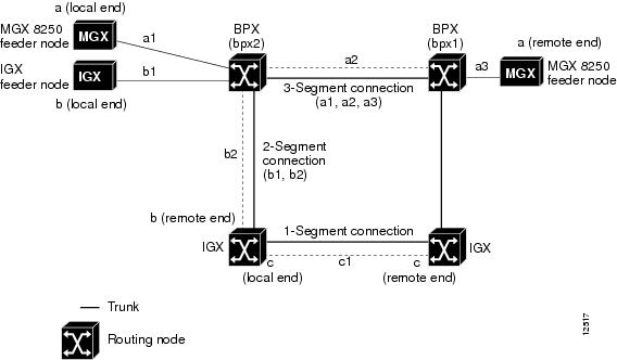

 Feedback