Cisco Configuration Professional Express 3.4 Feature Guide
Available Languages
Table of Contents
Cisco Configuration Professional Express 3.4 Feature Guide
Configuration Using CCP Express Advanced Mode
CCP Express Landing Page, Navigation, and Options
Setting Up Ethernet Primary WAN Uplink
Setting Up Ethernet Primary WAN Uplink with 3G/4G as Backup
Setting Up xDSL WAN Uplink for Wired/Wireless Internet Access in IPv4 Network
Setting Up xDSL Primary WAN Uplink in IPv6 Network
Setting Up xDSL Primary WAN Uplink
Setting Up 3G/4G WAN Primary Uplink
Setting Up 3G CDMA WAN Primary Uplink
Setting Up 3G GSM WAN Primary Uplink
Setting Up 4G WAN Primary Uplink
Setting up Serial Primary Uplink
Setting Up Primary xDSL with Backup 3G/4G WAN Uplink
Basic Diagnostic and Troubleshooting
Authentication Servers / Services
Configuring WAN for Cisco 800M Series Routers
Setting Up 3G GSM WAN Primary Uplink
Setting Up 3G CDMA WAN Primary Uplink
Setting Up Serial WAN Primary Uplink
Setting Up Ethernet WAN Primary Uplink
Setting Up 3G GSM Back up WAN Uplink
Setting Up 3G CDMA WAN Back Up Uplink
Setting Up Serial WAN Back Up Uplink
Setting Up Ethernet WAN Back Up Uplink
Configuring a LAN with DHCP and VLANs
Download Running Configuration
Timezone and NTP Configuration
Binding Interface, VTY and HTTP
Overview
The Cisco Configuration Professional Express (Cisco CP Express) is an embedded, device-management tool that provides the ability to bootstrap and provision an Integrated Services Router (ISR).
The Cisco CP Express helps you set up a network with complete WAN and LAN configuration, along with wireless access and Security features. Security features will be supported only if the IOS version is 15.5(1)T and above and security license is enabled.
All the configuration done through CCP Express is saved into startup configuration by default. When you use CCP Express for configuring a device, do not delete or modify the configuration directly by logging onto the device which will lead to misconfiguration. Security tab will be enabled only when the Security license is enabled on the device and the IOS image is 15.5(1)T or later.
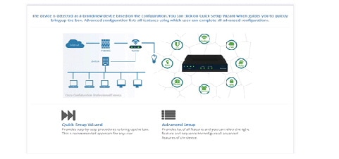
CCP Express provides you two options to bring up a brand new router. You can use the Quick Setup Wizard to perform the basic configuration tasks and Advanced Setup option for detailed configuration options. For a brand new router Quick setup wizard is the preferred option.
When you are running CCP Express for the first time, you can use the Quick Setup Wizard to quickly perform the basic router configuration tasks including setting up WAN, configuring LAN, and basic security configuration.
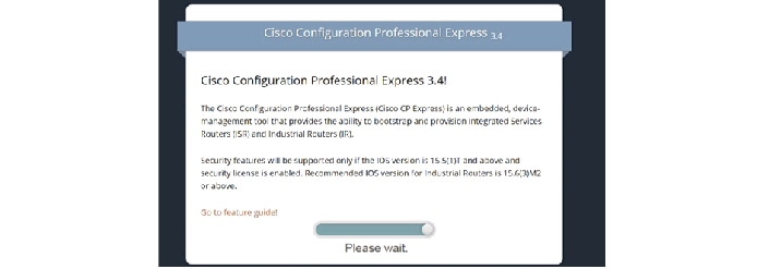
Splash Screen
Splash Screen is displayed when CCP Express is loading. This gives information about the current release and a link to the feature guide.
Using Quick Setup Wizard
Quick Setup Wizard helps you to quickly perform the basic router configuration when you are running the Cisco CP Express for the first time.
Perform the following steps to configure the router using quick setup wizard.
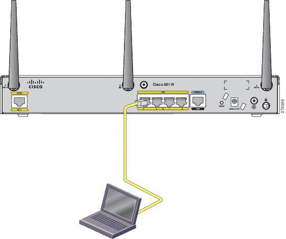
Step 1 Connect the PC to the Router using Ethernet cable as shown in Figure 2
Figure 2 Connecting PC to the Router
Step 2 Verify if the Cisco CP Express is installed correctly by performing the following steps:
b. In the address bar, type the IP address of the router where Cisco CP Express is installed.
For example, type http://10.10.10.1 or https://10.10.10.1
c. Provide the one-time-user-credentials. When router prompts for specifying new username and the password, please do the same.
e. Create a new user account and login with the new user credentials. Cisco CP Express Installation screen launches.
Step 3 Click Quick Setup Wizard from the Cisco CP Express Installation screen to run the Quick Setup Wizard.
Figure 3 Cisco CP Express Installation
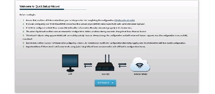
Step 4 Go through the configuration pre-requisites in the Quick Setup Wizard welcome screen and then click Get Started option.
Figure 4 Quick Setup Wizard Welcome Screen
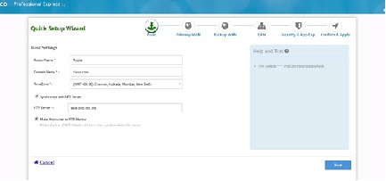
Step 5 Configure basic settings by entering Router Name, Domain Name and selecting the appropriate Time Zone.
Figure 5 Basic Router Settings Configuration
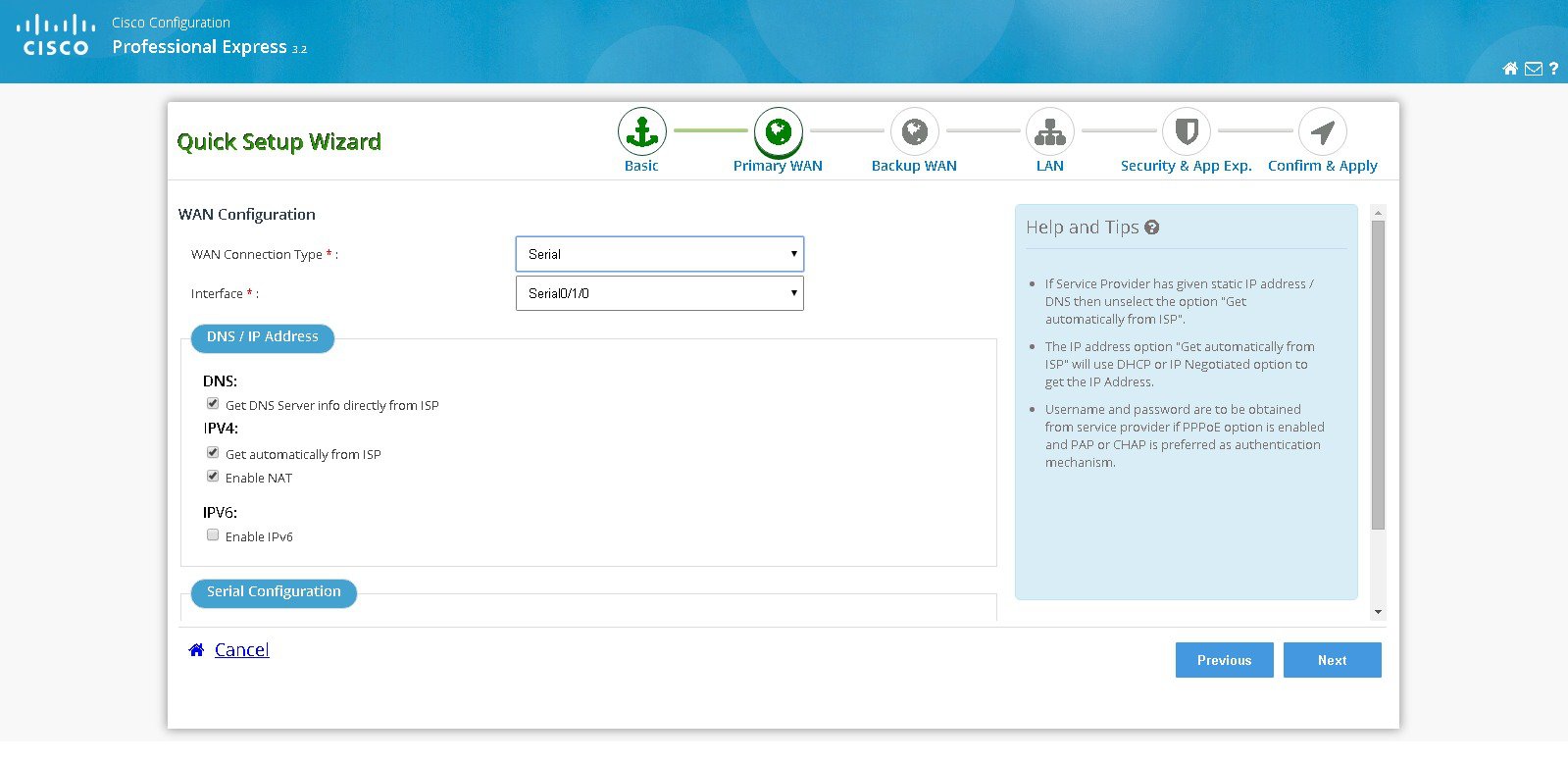
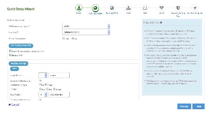
Step 6 Select the primary WAN type for configuring the primary WAN connection. You con configure Serial, 3G/4G, Ethernet, or Broadband (xDSL) as primary WAN depending on the WAN types supported by the router.
Figure 6 Primary WAN Configuration
See the following subtasks for each WAN option for configuring the required WAN:
- Cellular WAN Configuration for GSM
- Cellular WAN Configuration for CDMA
- Ethernet WAN Configuration
- xDSL WAN Configuration
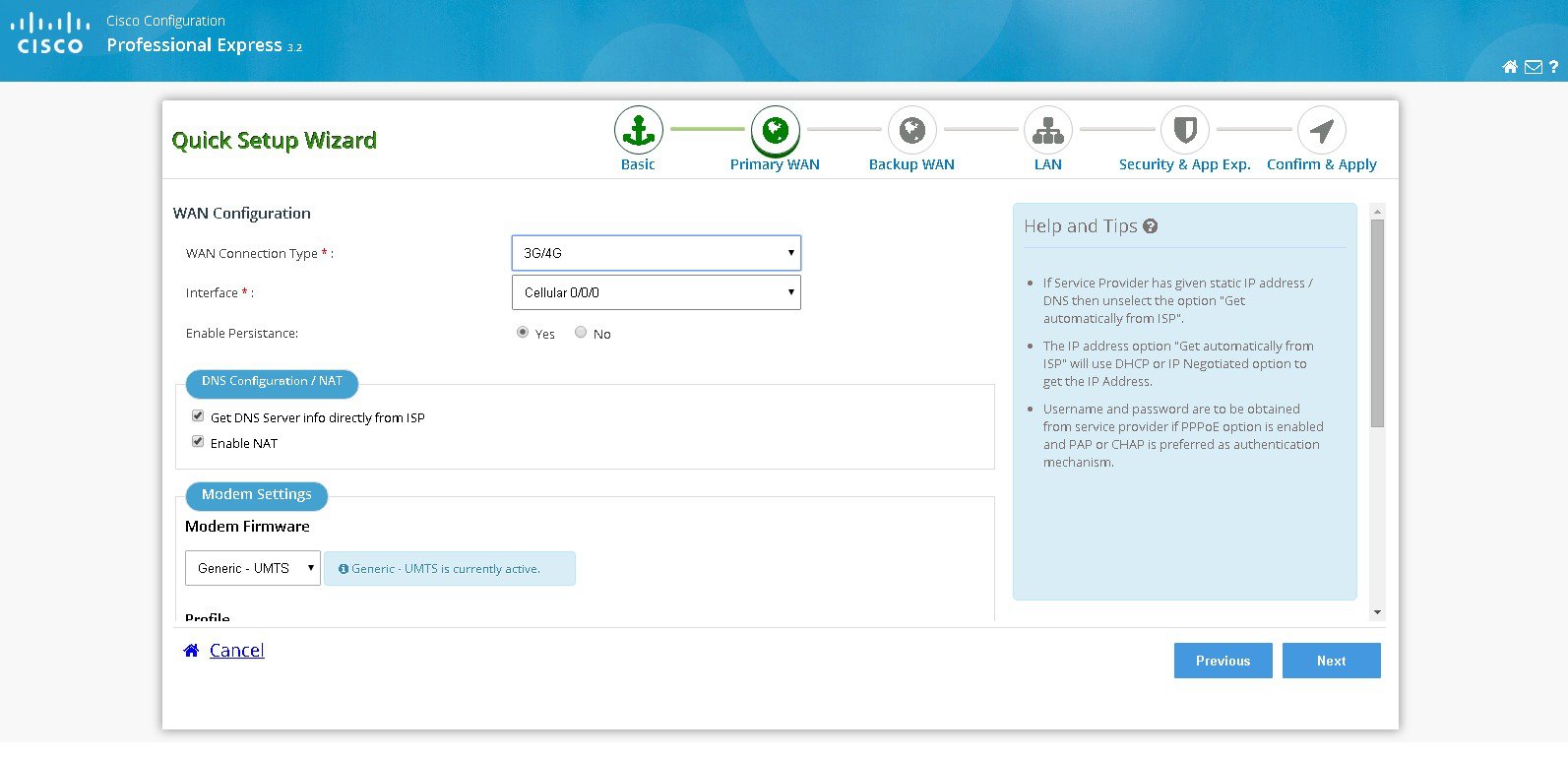
Cellular WAN Configuration for GSM
Perform the following steps to configure GSM cellular WAN:
a. Select the connected cellular WAN interface for configuring primary WAN.
b. Select enable persistence if you want to establish a persistent connection to your service provider from the dialer interface.
c. Get DNS server information directly from ISP is selected by default. If this option is enabled you cannot assign IP addresses statically.
d. There is an option to enable NAT and it is recommended to enable NAT.
e. Modem firmware is activated by default. Activate the corresponding modem firmware if you want to change the default modem firmware.
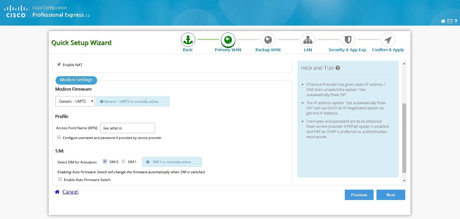
f. Enter the Access Point Name (APN) provided by the service provider for GSM profile configuration.

Note This step is applicable only for GSM configuration. GSM configuration options are available only if the selected firmware is UMTS.
g. Select the option Configure username and password if provided by service provider.
h. Select the SIM for activation. If you enable the auto firmware switch option to automatically switch over the firmware when you switch the SIM cards.
Note You should know the SIM type you have inserted on the Router.
Note SIM activation and auto firmware switch option is not available on some of the Cisco ISR routers.
i. Select Global System for Mobile Communications (GSM) as 3G/4G WAN technology.
Figure 7 Cellular WAN Configuration for GSM
Cellular WAN Configuration for CDMA
Perform the following steps to configure CDMA cellular WAN:
a. Select the connected cellular WAN interface for configuring primary WAN.
b. Select enable persistence if you want to establish a persistent connection to your service provider from the dialer interface.
c. Get DNS server information directly from ISP is selected by default. If this option is enabled you cannot assign IP addresses statically.
d. There is an option to enable NAT and it is recommended to enable NAT.
e. Modem firmware is activated by default. Activate the corresponding modem firmware if you want to change the default modem firmware.
f. Select the SIM for activation. If you enable the auto firmware switch option to automatically switch over the firmware when you switch the SIM cards.
Note You should know the SIM type you have inserted on the Router.
Note SIM activation and auto firmware switch option is not available on some of the Cisco ISR routers.
g. Select Code Division Multiple Access (CDMA) as 3G/4G WAN technology.
Figure 8 Cellular WAN Configuration for CDMA
Perform the following steps to configure serial WAN:
a. Select the serial interface for configuring Serial WAN.
b. Select the appropriate IP address configuration information based on whether you are configuring an IPv4 or IPv6 address. Specify the details for the IP address depending on whether the IP address is dynamically or statically assigned. There is an option to enable NAT configuration and it is recommended to enable NAT for WAN interfaces. The IPv6 address can be either AutoConfig, Use Prefix from Provider, or Static IP Address. If you have selected AutoConfig, enable Act as an IPv6 DHCP client option. If you have selected Prefix from Provider or Static IP Address option, enter Prefix and Prefix Mask details.
c. Select the required serial communication mode. You have synchronous and asynchronous options.
d. Select the required serial encapsulation type. You have HDLC and PPP options for synchronous mode and SLIP and PPP options for asynchronous mode. For PPP you have PAP and CHAP options.
Figure 9 Serial WAN Configuration
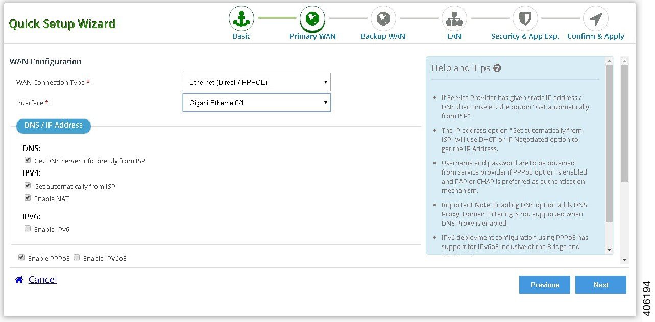
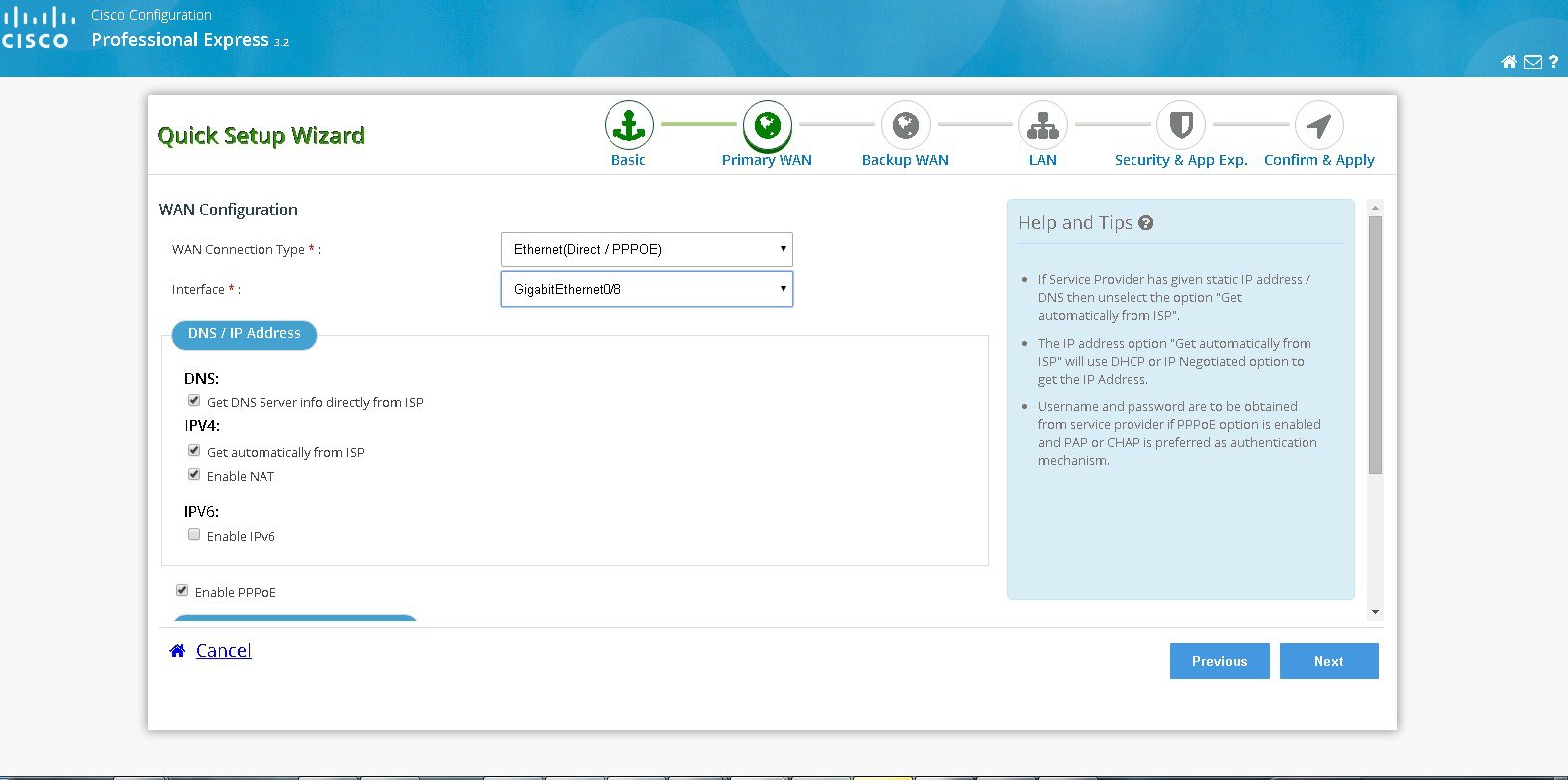
Perform the following steps to configure Ethernet WAN:
a. Select the Ethernet interface for configuring Ethernet WAN.
b. Select the appropriate IP address configuration information based on whether you are configuring an IPv4 or IPv6 address. Specify the details for the IP address depending on whether the IP address is dynamically or statically assigned. There is an option to enable NAT configuration and it is recommended to enable NAT for WAN interfaces. The IPv6 address can be either AutoConfig, Use Prefix from Provider, or Static IP Address. If you have selected AutoConfig, enable Act as an IPv6 DHCP client option. If you have selected Prefix from Provider or Static IP Address option, enter Prefix and Prefix Mask details.
c. If you have enabled PPPoE, select the required authentication mode. You have PAP and CHAP options.
d. Enter the user name and password provided by the service provider.
Figure 10 Ethernet WAN Configuration
Perform the following steps to configure xDSL WAN:
a. Select the controller (VDSL, SHDSL or ADSL), appropriate mode and interface.
Note Mode information can be obtained from the service provider. If the mode is not exactly known, then select mode as Auto.
b. Select the appropriate IP address configuration information based on whether you are configuring an IPv4 or IPv6 address. Specify the details for the IP address depending on whether the IP address is dynamically or statically assigned. There is an option to enable NAT configuration and it is recommended to enable NAT for WAN interfaces. The IPv6 address can be either AutoConfig, Use Prefix from Provider, or Static IP Address. If you have selected AutoConfig, enable Act as an IPv6 DHCP client option. If you have selected Prefix from Provider or Static IP Address option, enter Prefix and Prefix Mask details.
c. Under connection and authentication, provide the encapsulation key for Ethernet Interface. For ATM interface provide VPI and VCI information. If enable PPPoE is selected, select PAP or CHAP as the authentication method and enter the user name and password provided by the service provider.
Figure 11 xDSL WAN Configuration
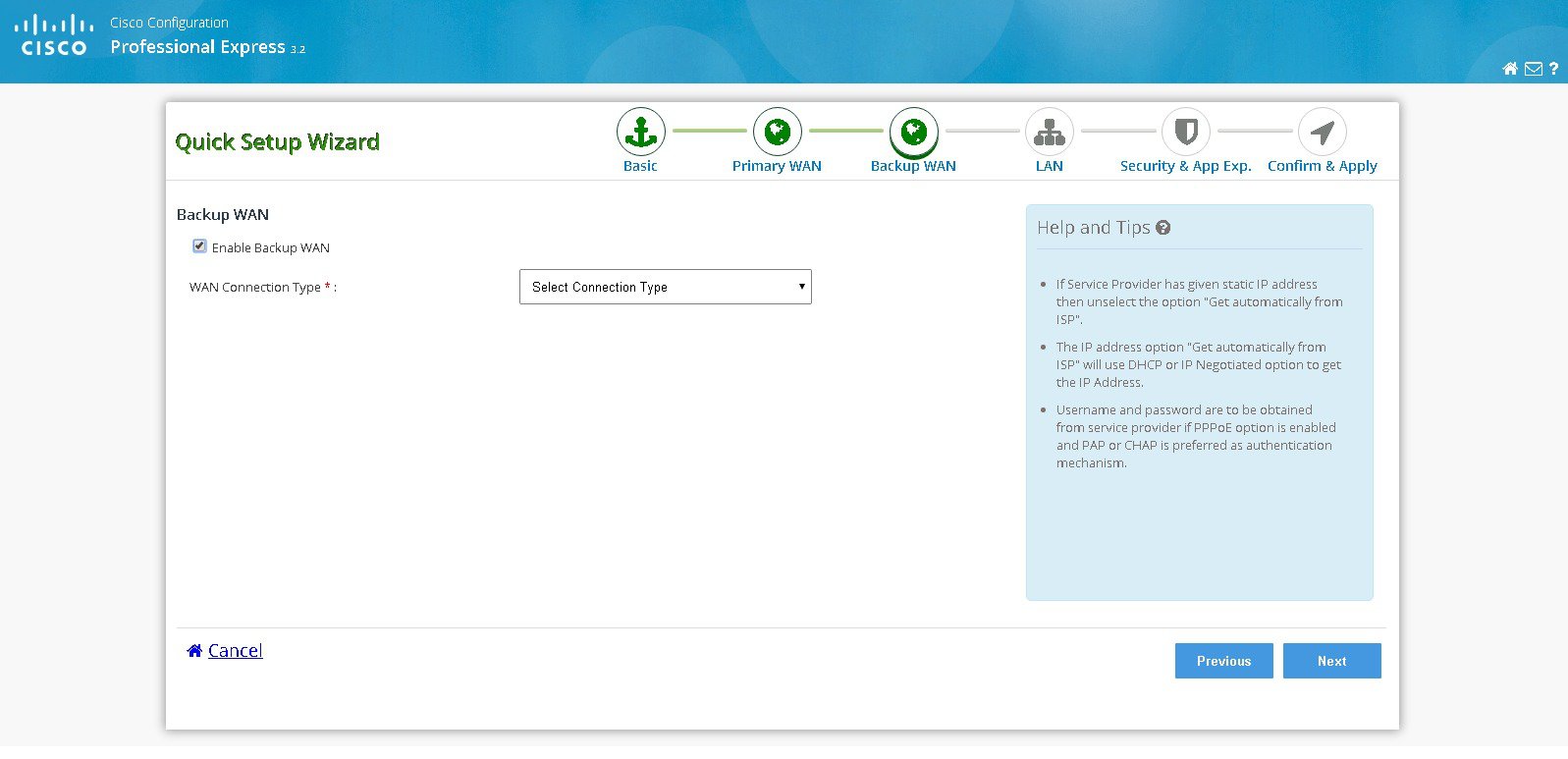
Step 7 Select Enable Backup WAN option if you want to configure Back Up WAN. Follow the configuration sub tasks in step 4 to configure the desired Back Up WAN type and then click Next .
Figure 12 Backup WAN Configuration
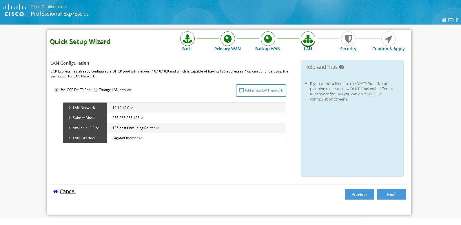
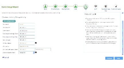
Step 8 Click Next to complete the LAN configuration since DHCP pool will be automatically configured and you can use the same DHCP pool for LAN network.
Step 9 To perform LAN configuration, follow below steps:
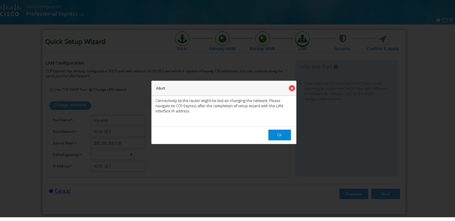
e. Select Change LAN network to edit the existing network. LAN Configuration.
Figure 13 LAN Configuration Page
f. You will be getting a confirmation alert message before changing the existing network and click OK to proceed.
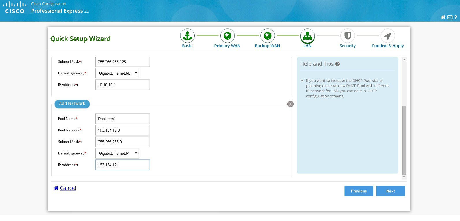
g. If you want to add a new LAN network, select add a new LAN network option.
h. Configure new network with Pool name, Pool network, Subnet Mask and IP address.
Figure 15 Configuration with LAN Network
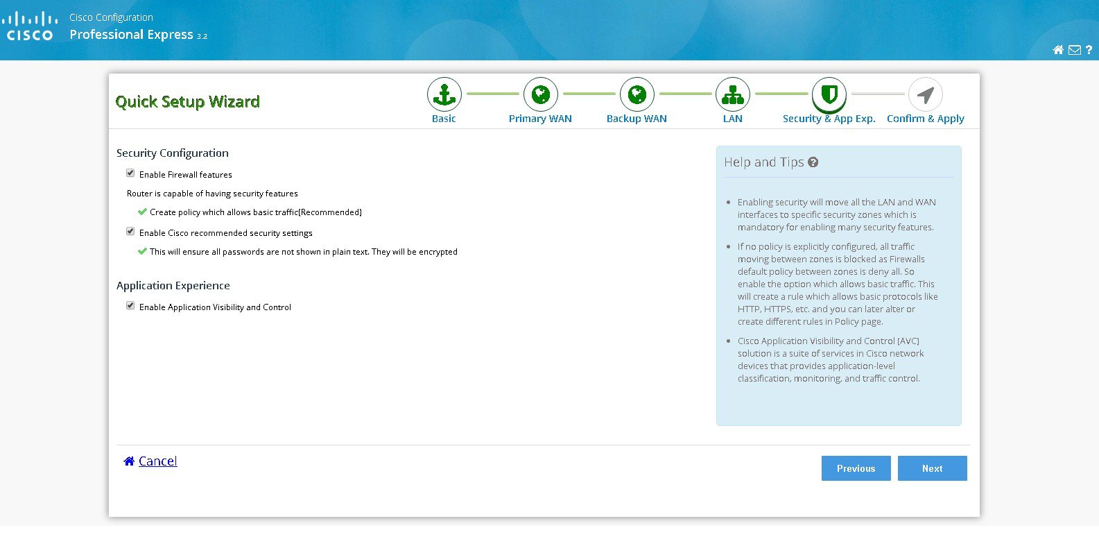
Step 10 Click Next to configure security.
i. Select Enable firewall features and then select create policy which allows basic traffic option to configure the security features and then click Next.
Figure 16 Security Configuration
Step 11 Click Submit to confirm the configuration changes in the summary screen.
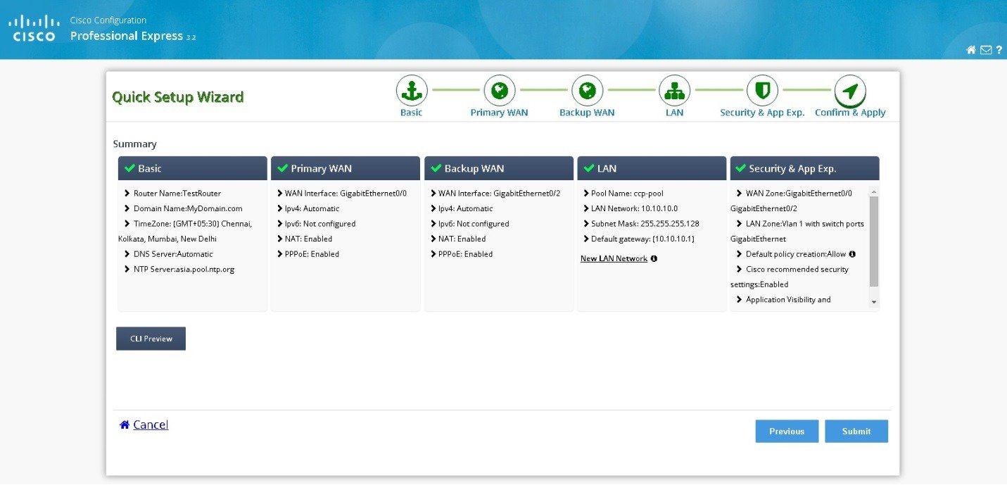
Step 12 A message appears saying configuration may take some time to configure and whether you want to continue the configuration. Click Yes to continue the configuration changes.
Step 13 Configuration using the Quick Setup Wizard is complete and a completion message appears.
Figure 18 Configuration Completion using Quick Setup Wizard
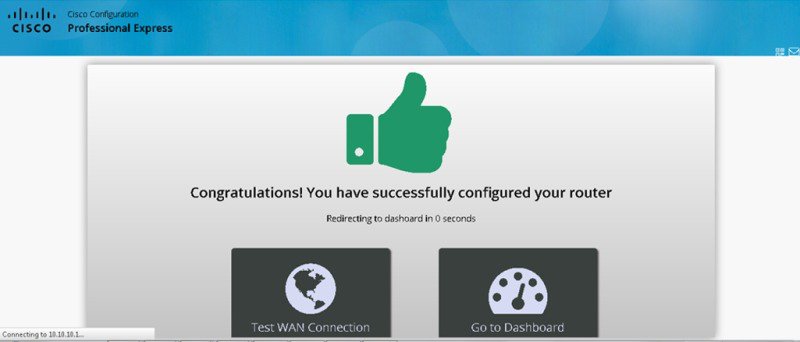
Step 14 (Optional) If you want to check the status of your WAN connection click Test WAN Connection .
Note For Cisco IR8x9 Series routers, the configuration wizard screens are different.
Cellular WAN Configuration for Cisco IR8x9 Devices
a. Select the connected cellular WAN interface for configuring the primary WAN.
b. Select enable persistence if you want to establish a persistent connection to your service provider from the dialer interface.
c. The Get DNS server information directly from ISP option is selected by default. If this option is enabled, you cannot assign IP addresses statically.
d. The modem settings section allows you to configure the SIMs.
Note Ensure that the profile information is retrieved from the Service Provider in advance. The dual LTE version of the Cisco IR829 have 2 SIMs and you have to configure both the SIMs. The Cisco IR829 and Cisco IR809 single LTE have only one SIM.
Figure 20 Cellular WAN Interface for IR829 Dual LTE
IOX Configuration for IR Devices
a. In the IOX tab, slide the button towards the left to enable IOX access.
b. If NAT is not enabled, a message is displayed about the status of the NAT.
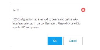
c. Click OK to proceed with the IOX configuration. Default configuration details are displayed.
Figure 23 IOX Default Configuration
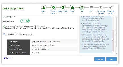
d. You have the options to change the configuration as required.
Figure 24 Modify Default IOX configuration
WIFI Configuration for Cisco IR829
a. In the IOX tab, slide the button towards the left to turn on the WIFI connection.
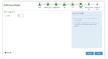
b. Enter the Network Name, Security Type, and Password for WPA and WPA2 to be configure SSID on the Access Point The default value that is set for the BVI Interface IP Address is loaded.
Note You can change the IP Address of BVI Interface.
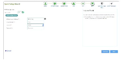
c. Click Next to proceed with the WIFI configuration.
d. You have the options to change the configuration as required.
Configuration Using CCP Express Advanced Mode
This section explains how to configure Cisco ISR G2 routers using CCP Express advanced mode. The screens and configuration steps may slightly vary depending on the WAN configuration options and the software features supported by the Cisco ISR G2 router.
Note For Cisco 800M series routers, the configuration screens for WAN configuration is slightly different. For WAN configuration steps for the Cisco 800M series routers, see the “Configuring WAN for Cisco 800M Series Routers” section
CCP Express Landing Page, Navigation, and Options
Figure 27 shows CCP Express landing page where you can navigate to all the features.
Figure 27 CCP Express Landing Page
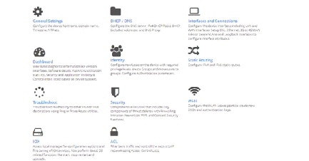
Figure 28 shows the various features at the top menu which will be available in all the advanced mode.
Figure 28 Features in Advanced Mode

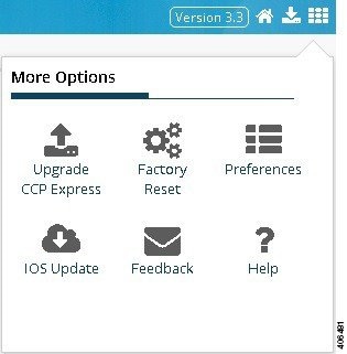
Figure 29 User Options allows you to navigate, and Upgrade CCP Express, Upgrade IOS, Factory Reset, Preferences, Feedback, Help, Quick Setup Wizard.
Setting Up Ethernet Primary WAN Uplink
This section explains how to set up an Ethernet primary WAN uplink and enable wired or wireless Internet access for clients in an IPv4 or IPv6 networks. To set up an Ethernet primary WAN uplink and enable wired or wireless Internet access, perform these steps:
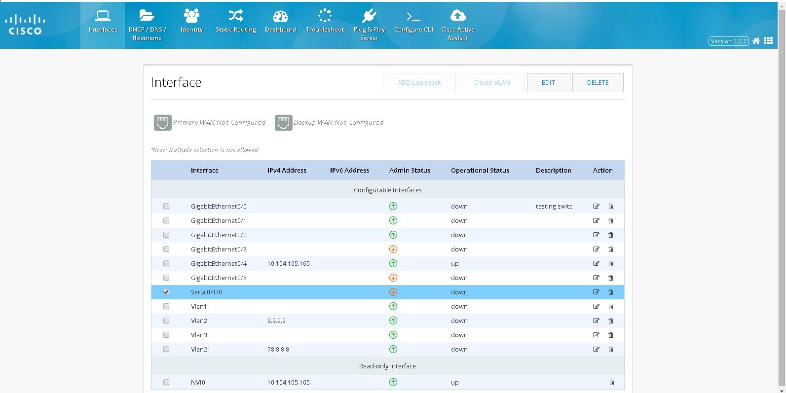
Step 1 Click Interfaces to open the Interfaces page.
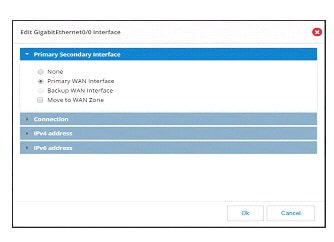
Step 2 From the list of interfaces, select the interface to which WAN is connected, and click Edit. The Edit Interface page is displayed.
– In Edit Interface > Primary Secondary Interface, check Primary WAN Interface option and this will ensure that default route created for this WAN Interface
– If the device supports Security then “Move to WAN Zone” option will appear and user can enable this to make the WAN interface part of WAN Zone. Having the WAN interface part of WAN Zone is the mandatory requirement for many security features.
Step 3 From Edit Interface > Connection page, check Enable PPPoE check box, and enter the description in the Description field.
Step 4 From the Edit Interface page, specify the details for IP address depending on whether the IP address is dynamically or statically assigned. There is an option to enable NAT configuration and the recommendation is to enable NAT for WAN interfaces. This will create NAT overloading configuration hence all LAN IPs are translated to public IP before being sent to WAN up link.
Step 5 (Optional) Configure wired or wireless LAN by executing Steps 2 to 14 of the section Setting Up xDSL WAN Uplink for Wired/Wireless Internet Access in IPv4 Network.
Step 6 From Edit Interface > Authentication page, check CHAP or PAP check box and specify the username and password given by Service provider
Setting Up Ethernet Primary WAN Uplink with 3G/4G as Backup
This section explains how to set up an Ethernet primary WAN uplink with 3G or 4G as a backup. To set up an Ethernet primary WAN up link with 3G or 4G as a backup, perform these steps:
Step 1 Click Interfaces to open the Interfaces page.
Step 2 From the list of interfaces, select the interface to which your WAN is connected, and click Edit.
The Edit Interface page is displayed.Step 3 From the Edit Interface page, specify the details for the IP address depending on whether the IP address is dynamically or statically assigned.
Step 4 Check the Enable NAT check box to ensure that DHCP client IP addresses are translated before being sent to the WAN uplink.
Step 5 (Optional) Configure your wired or wireless LAN by executing Steps 2 to 14 of the section Setting Up xDSL WAN Uplink for Wired/Wireless Internet Access in IPv4 Network.
Step 6 Click Interfaces to open the Interfaces page.
Step 7 From the Interfaces page, select the 3G Interface and click Edit to edit the configuration.
Step 8 Based on your 3G modem account, specify the modem account or modem activation information.
For more information, see sections Setting Up 3G CDMA WAN Primary Uplink and Setting Up 3G GSM WAN Primary Uplink sections.Step 9 From the WAN interface, select Backup WAN Interface and select your primary WAN interface. This is the Ethernet interface you configured in Step 2.
Step 10 Specify the IP address of a reliable network on which the connectivity can be verified.
Step 11 If you want to establish a persistent connection to your service provider, from the Dialer interface, select YES.
By default, this is set to NO to disable persistent connection.Step 12 Click OK to set up an Ethernet primary WAN uplink with 3G or 4G as backup.
Setting Up xDSL WAN Uplink for Wired/Wireless Internet Access in IPv4 Network
This section explains how to set up an xDSL WAN uplink and enable Wired/Wireless Internet access for clients in an IPv4 network. To set up a WAN uplink and enable Wired/Wireless Internet access, perform these steps:
Step 1 After you complete configuring your xDSL as described in Setting Up xDSL Primary WAN Uplink, create a new DHCP pool.
Step 2 Click Basic Settings to open the Basic Settings page (Figure 35).
Step 3 From the DHCP interface, click Add to create a new DHCP pool by specifying:
- Pool Name: the name of the DHCP pool
- Pool Network: the IP address of the subnet that represents all IP addresses allocated to the wired or wireless clients
- Import all DHCP options in to the DHCP server database: Check this check box to import all DHCP options into the DHCP server database. This ensures that the DNS is read from your service provider and is propagated to all DHCP clients.
- Enable Trunk on wlan-gigabitEthernet0: Uncheck this check box if you want to allow only VLAN1 for wired or wireless access. By default, this check box is enabled, and allows multiple VLANs (including VLAN1) to access wired or wireless Internet.
Step 4 Click OK to create the DHCP pool.
Step 5 Click Interfaces to open the Interfaces page (Figure 32).
Step 6 Click Add VLAN to open the Add VLAN dialog box and specify a unique ID for the VLAN being created.
Step 7 From the IPv4 address tab, choose Select from DHCP, and then select the DHCP pool (created in Step 3) from the drop-down list.
This enables you to assign the IP addresses from the DHCP pool that is created.Step 9 Click Wi-Fi to open the Wireless page.
Step 10 Specify an SSID that will be used to uniquely identify your wireless device.
The SSID can contain up to 32 alphanumeric characters.Step 11 To broadcast the SSID in the access point beacon, check the Broadcast SSID in Beacon check box.
When you broadcast the SSID, devices that do not specify an SSID can associate with the access point. This is a useful option for an SSID used by guests or by client devices in a public space. If you do not broadcast the SSID, client devices cannot associate to the access point unless their SSID matches this SSID. Only one SSID can be included in the access point beacon.Step 12 Select the Enable VLAN ID and specify the ID of the VLAN created in Step 6.
This will enable the clients that connect to the SSID (specified in Step 10) to use the IP addresses from the DHCP pool associated with this VLAN.Step 13 Select the security setting for the SSID.
Step 14 Click Apply.
The SSID appears in the SSID table on the bottom of the page.
Setting Up xDSL Primary WAN Uplink in IPv6 Network
You can use Cisco CP Express to configure both DHCPv6 (Dynamic Host Configuration Protocol for IPv6) server and client. Cisco CP Express supports only the Prefix Delegation method for configuring IPv6 addresses. For more information, refer http://www.cisco.com/en/US/tech/tk872/technologies_configuration_example09186a0080b8a116.shtml.
To set up an xDSL primary WAN uplink in an IPv6 network using Prefix Delegation method, perform these steps:
Step 1 Click Interfaces to open the Interfaces page.
Step 2 Select the DSL Interface where the configuration is to be done whether it is main interface or sub-interface (ATM0 or Ethernet0) and click on Edit to edit the interface configuration.
Note Based on your DSL uplink, select the appropriate layer 2 interface. For an ADSL uplink, select ATM0 as your layer 2 interface, and for a VDSL uplink, select Ethernet0 as your layer 2 interface.
Step 3 From the Connection tab, enable PPoE, provide a description, the VPI, and the VCI values for your connection.
Step 4 From the IPv4 Address tab, select No IP Address.
Step 5 From the IPv6 Address tab, select Autoconfig and check the Act as an IPv6 DHCP Client check box.
Step 6 From the Authentication tab, select the authentication method and specify the username and password provided by your service provider for authentication.
Step 7 Click OK to complete the configuration.
You must now edit your VLAN to configure it for IPv6 support.Step 8 From the Interfaces page, select a VLAN interface and click Edit to edit the configuration.
Step 9 Specify the VLAN ID and associate the ports to the VLAN.
Step 10 From the IPv4 Address tab, select No IP Address.
Step 11 From the IPv6 Address tab, select Use Prefix from Provider as the type, and specify the prefix and the prefix mask.
Setting Up xDSL Primary WAN Uplink
To set up an xDSL primary WAN uplink, perform these steps:
Step 1 Click Interfaces to open the Interfaces page.
Step 2 Select the controller (may be VDSL, SHDSL, ADSL etc) and select the mode and click on Configure Interface and that will show the appropriate interfaces for the selected mode. Choose the right interface (either ATM or Ethernet).
Note Note: Mode info can be obtained from the service provider. If the mode is not exactly known, then select mode option as Auto and click on OK button. Also ensure that WAN interface is connected. Check the controller after few minutes by executing show controller controller and see which interface is trained by the service provider. Then select the trained interface by editing the interface and complete the configuration.
Step 3 In Primary Secondary Interface section select interface as Primary and this will configure the default route. If it is marked as “None” then default route will not be configured.
If the device supports Security then “Move to WAN Zone” option will appear and user can enable this to make the WAN interface part of WAN Zone. Having the WAN interface part of WAN Zone is the mandatory requirement for many security features.
Step 4 In Connection section, select Enable PPPoE check box, and enter the description in the Description field. For Ethernet Interface provide encapsulation and for ATM provide VPI and VCI. This will create a specific sub interface and configure them accordingly. If the encapsulation is not given then configuration will be done under main interface.
Step 5 Based on whether you are configuring an IPv4 or IPv6 address, select the appropriate tab. Specify the details for the IP address depending on whether the IP address is dynamically or statically assigned.
This can be either Easy IP (IP Negotiated), Static IP Address, or No IP Address. By default, the IPv4 address is IP negotiated.
There is an option to enable NAT configuration and the recommendation is to enable NAT for WAN interfaces. This will create NAT overloading configuration hence all LAN IPs are translated to public IP before being sent to WAN uplink.
For configuring an IPv6 address:
– Select the IPv6 address type.
The IPv6 address can be either AutoConfig, Use Prefix from Provider, Static IP Address, or No IP Address.
Note To edit the configuration you can select controller, or directly select the interface or sub interface based on the configuration done.
Note To edit the configuration you can select controller, or directly select the interface or sub interface based on the configuration done.
Note Cisco CP Express supports only the Prefix from Provider approach for IPv6 address configuration.
Step 6 From the Authentication tab, select the authentication method (PAP or CHAP) and specify the username and password provided by your service provider.
Step 7 Click OK to create the DSL uplink.
Setting Up 3G/4G WAN Primary Uplink
This section explains how to set up a 3G WAN primary uplink (for CDMA and GSM) with Wired or Wireless LAN access.
Setting Up 3G CDMA WAN Primary Uplink
Based on the type of 3G modem, the activation method can either be OMA-DM, OTASP, or Manual (Fallback). You must collect this account information from your service provider:
- If your 3G interface uses Manual (Fallback) as the activation method, obtain the Mobile Directory Number (MDN), Mobile Subscriber Identification Number (MSID), and the Mobile Subscriber Lock (MSL) No. from your service provider and specify these in the Account Information tab.
- If your 3G interface uses OTASP as the activation method, obtain the Phone No. for activation from your service provider and specify it in the Account Information tab.
To set up a 3G CDMA WAN primary uplink, perform these steps:
Step 1 Click Interfaces to open the Interfaces page.
Step 2 Select the 3G Interface you want to configure and click Edit.
The Edit Cellular Configuration page is displayed ().Figure 33 The Edit Cellular Configuration page
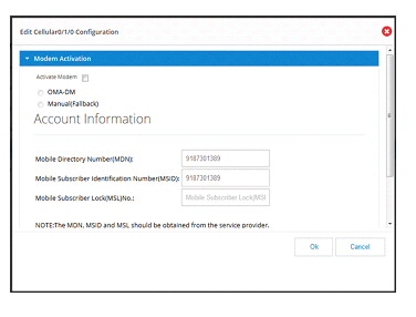
Step 3 From the Modem Activation tab, check the Activate Modem checkbox to activate your modem, select the activation method and provide the necessary information. The modem activation method can either be OMA-DM, OTASP, or Manual (Fallback).
Step 4 From the WAN tab, select Primary WAN Interface. If the device supports Security then “Move to WAN Zone” will appear and user can make the WAN interface part of WAN Zone. Having the WAN interface part of WAN Zone is mandatory requirement for many security features.
Step 5 If you want to establish a persistent connection to your service provider, from the Dialer interface, select YES.
By default, this is set to NO to disable persistent connection.
Note A persistent connection is an always “ON” connection. It sends keep alive packets to keep the connection live.
A non-persistent connection is an on-demand connection, in which the modem dials out only when the data tries to go in or out of that interface. If no data ID is flown for 60 seconds, the connection is dropped and the modem dials out again when the data tries to go in or out.
Setting Up 3G GSM WAN Primary Uplink
Before you begin setting up your 3G GSM WAN primary uplink, make sure your obtain the Access Point Name (APN), the PDP type, authentication method, and the username and password from your service provider.
To set up a 3G GSM WAN primary uplink, perform these steps:
Step 1 Click Interfaces to open the Interfaces page.
Step 2 Select the 3G Interface you want to configure and click Edit.
The Edit Cellular Configuration page is displayed (Figure 34).Figure 34 Editing Modem Account Details on the Edit Cellular Configuration page
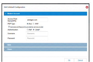
Step 3 From the Modem Account tab, specify the APN for your modem account.
Note If your service provider has not provided the PDP type, username, and password for your modem account, make sure you uncheck the "Username and Password is provided by service provider” check box and proceed to Step 7.
Step 4 Select the Packet Data Protocol (PDP) type.
This can either be IPv4 or PPP. By default, this is IPv4.Step 5 Check the Username and Password is provided by service provider check box and specify the username and password for your modem account.
Step 6 Select the Authentication method.
This can either be PAP or CHAP.Step 7 From the WAN tab, select Primary WAN Interface as your 3G uplink. If the device supports Security then “Move to WAN Zone” will appear and user can make the WAN interface part of WAN Zone. Having the WAN interface part of WAN Zone is mandatory requirement for many security features.
Step 8 If you want to establish a persistent connection to your service provider, from the Dialer interface, select YES.
By default, this is set to NO to disable persistent connection.
Note If Cellular is configured as Primary WAN Interface other interface cannot be marked as secondary Interface. Also, if Cellular needs to be configured as secondary, then in the same Cellular screen Primary interface has to be configured.
Setting Up 4G WAN Primary Uplink
To set up a 4G WAN primary uplink, perform these steps:
Step 1 Click Interfaces to open the Interfaces page.
Step 2 Select the 4G Interface you want to configure and click Edit.
The Edit Cellular Configuration page is displayed.Step 3 From the WAN tab, select Primary WAN Interface as your 4G uplink.
Step 4 If you want to establish a persistent connection to your service provider, from the Dialer interface, select YES.
By default, this is set to NO to disable persistent connection.
Setting up Serial Primary Uplink
To set up a serial primary uplink, perform these steps:
Step 1 Click Interfaces to open the Interfaces page.
Step 2 Select a serial interface and click on the Edit button.
Step 3 From the available Primary Secondary Interface, select Primary WAN Interface or Backup WAN Interface.
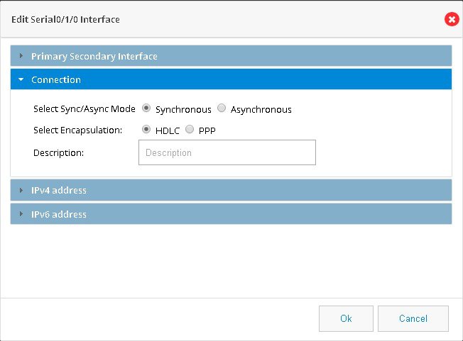
Step 4 Make a selection for Connection mode as Synchronous or Asynchronous and Encapsulation as HDLC or PPP. (Figure 35)
Step 5 Provide a description for the connection.
Step 6 Select an IPv4 address as Static IP, DHCP or Easy IP.
Step 7 Select an IPv6 address as Static IP, Prefix from Provider or Autoconfig.
Step 8 Save the interface by clicking on OK.
Figure 35 Setting up Serial Primary Uplink
Setting Up Primary xDSL with Backup 3G/4G WAN Uplink
To set up primary xDSL with backup 3G/4G WAN uplink, perform these steps:
Step 1 Click Interfaces to open the Interfaces page.
Step 2 Select the sub-interface (either ATM0 or Ethernet0) and click Edit to edit the interface configuration.
Note Based on your DSL uplink, select the layer 2 interface. For an ADSL uplink, select ATM0 as your layer 2 interface, and for a VDSL uplink, select Ethernet0 as your layer 2 interface.
Step 3 From the Connection tab, enable PPoE, provide a description, the VPI, and the VCI values for your connection.
Step 4 From the IPv4 Address tab, select Easy IP (IP Negotiated) and check the Enable NAT check box.
Step 5 From the Authentication tab, select the authentication method and specify the username and password for authentication.
Step 6 Click OK to create the DSL uplink.
Step 7 After you create the DSL uplink, select the sub-interface created in Step 6, and then click Edit.
Step 8 Navigate to the IPv4 Address tab to find the dialer associated with this sub-interface.
The 3G backup link uses this dialer information to find its primary uplink when the DSL is down.Step 9 From the Interfaces page, select the 3G Interface and click Edit to edit the configuration.
Step 10 Based on your 3G modem account, specify the modem account or modem activation information.
For more information, refer the Setting Up 3G CDMA WAN Primary Uplink and Setting Up 3G GSM WAN Primary Uplink sections.Step 11 From the WAN interface, select Backup WAN Interface and select your primary WAN interface (this is the dialer created in Step 8).
Step 12 Specify the IP address of a reliable network to which the connectivity can be verified.
Step 13 If you want to establish a persistent connection to your service provider, from the Dialer interface, select YES.
By default, this is set to NO to disable persistent connection.
Plug-and-Play Server Feature
This is a legacy Plug-and-Play application and the support for this application has been dropped in the Cisco Configuration Professional Express 3.3 release.
Basic Diagnostic and Troubleshooting
This section explains how to perform basic diagnostic and troubleshooting for your router.
Ping and Traceroute
The Ping and Traceroute utility allows you to do a basic troubleshooting of the network and device connectivity.
To troubleshoot the device connectivity, perform these steps:
Step 1 Click Troubleshoot to open the Ping and Traceroute page.
Figure 36 Ping and Traceroute Page
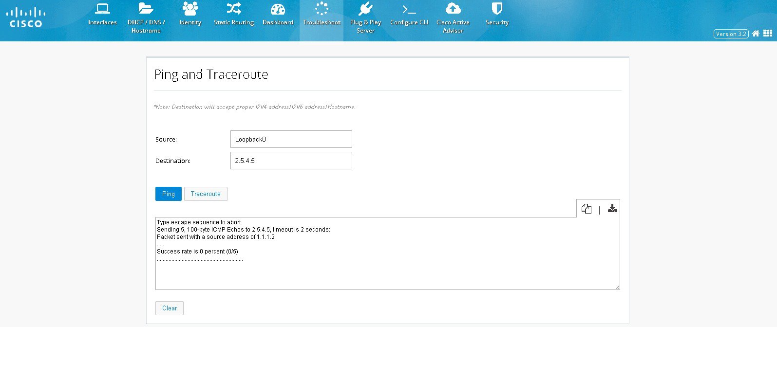
Step 2 (Optional) Specify the source IP address (IPv4 or IPv6 address) or interface.
Step 3 Specify the destination IP address (IPv4 or IPv6 address) or hostname.
Step 4 Click Ping to verify whether the destination IP address is reachable.
Step 5 Click Traceroute to view the list of routes traversed between the source and destination IP addresses.
Step 6 You can also copy-to-clipboard or download the retrieved data by clicking on COPY or DOWNLOAD icons to the right of the details box.
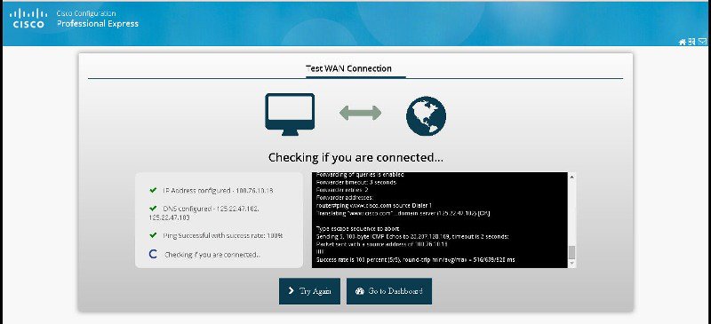
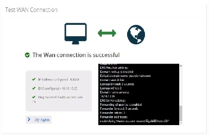
Test WAN Connection
This section allows you to check the WAN connectivity. The section automatically triggers checks once you navigate to this screen.
To test the WAN connection, perform these steps:
Step 1 Click Troubleshoot > Test WAN Connection to open the WAN connection page.
Figure 37 Test WAN Connection Page
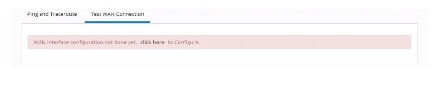
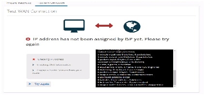
Figure 39 WAN Connection Success Message
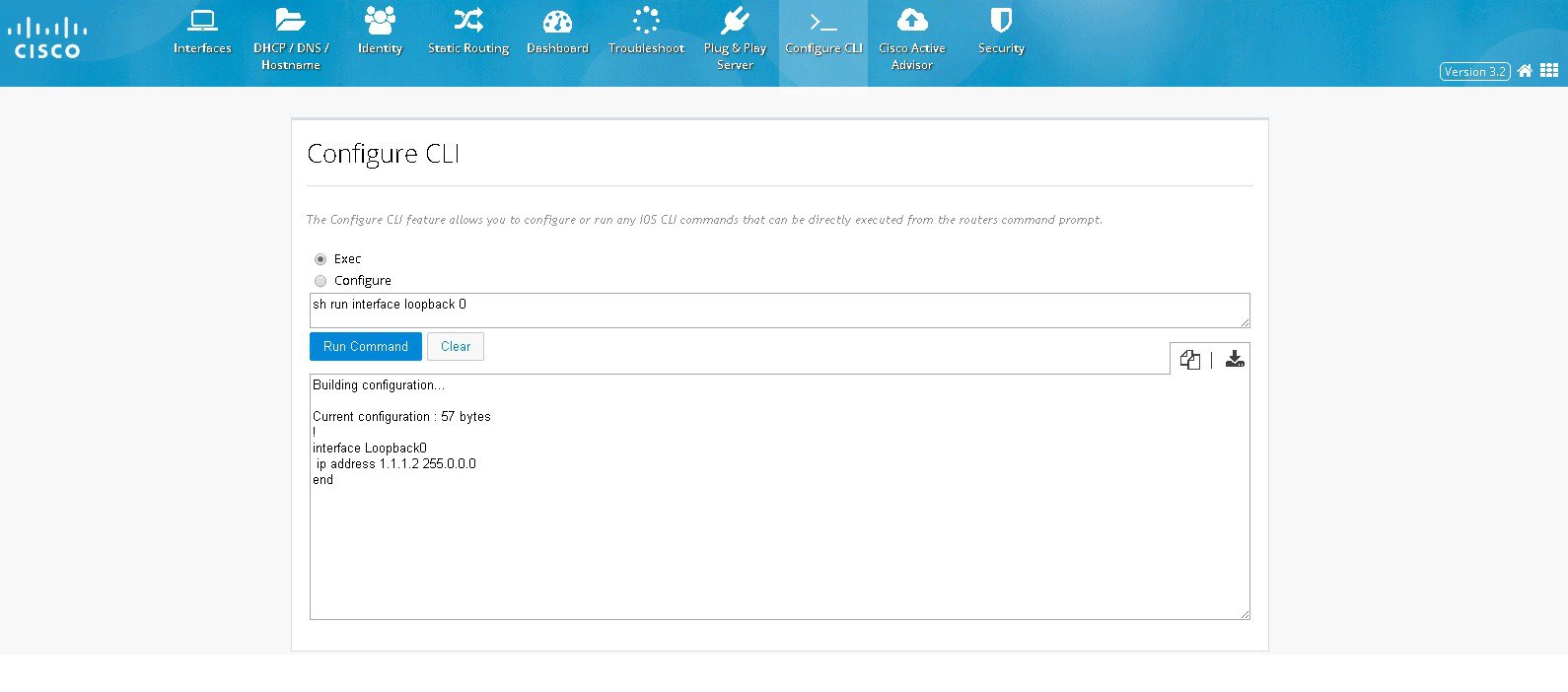
Configure CLI
The Configure CLI feature allows you to configure or run any IOS CLI commands that can be directly executed from the router’s command prompt.
To configure a CLI, perform these steps:
Step 1 Click Configure CLI to open the Any CLI configuration page.
Step 2 From the Configure CLI tab, select the mode in which you want to execute the CLI.
You can select either the Exec or Configure mode.Figure 40 An example of a command executed in Config mode
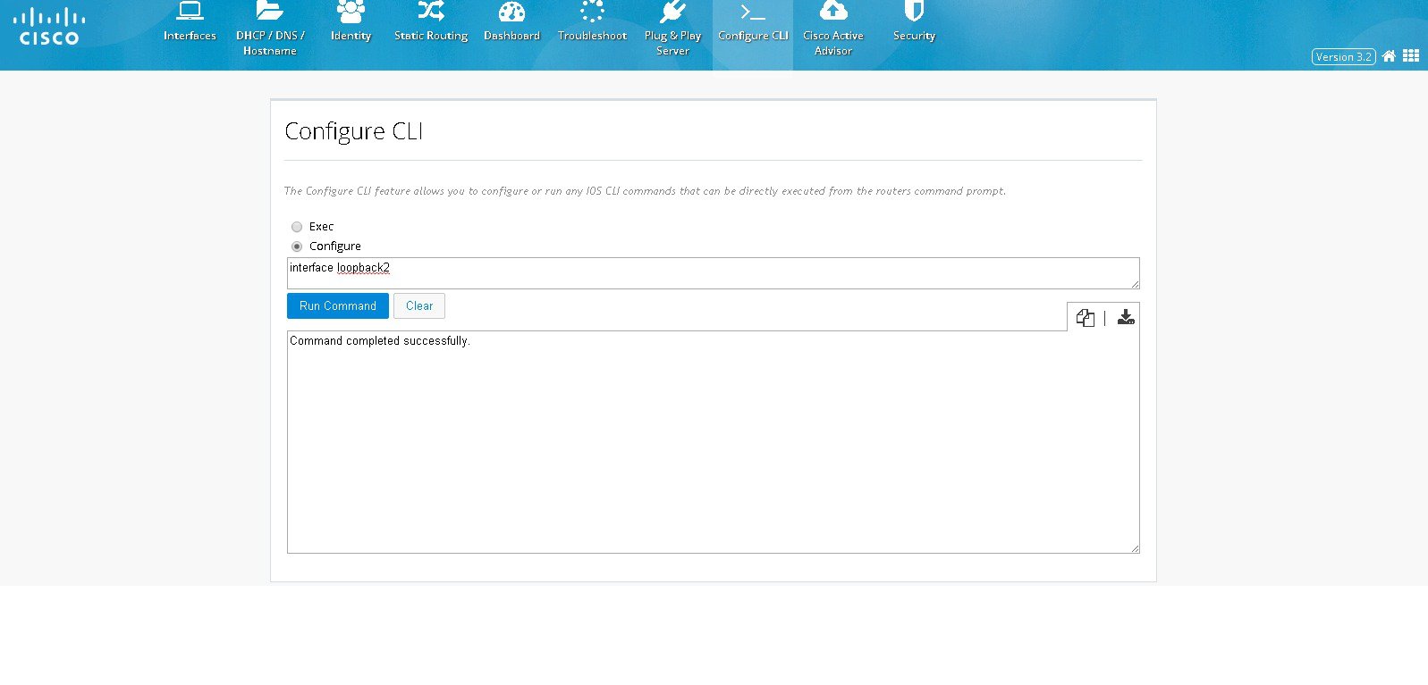
Figure 41 An example of a command executed in Exec mode
Step 3 In the text box, type the CLI you want to execute.
Step 4 Click Run Command to execute the CLI. The CLI’s output is displayed.
Step 5 You can also copy-to-clipboard or download the retrieved data by clicking on COPY or DOWNLOAD icons to the right of the details box.
Note Using the Configure CLI feature, you cannot configure interactive commands and service module related commands.
Dashboard
The Dashboard view shows the vital hardware health status of the router along with the flash and system memory, CPU utilization, and WAN Interface status and security aspects of network. The Dashboard has two sections Router and Security.
Viewing Router Dashboard
To view the router diagnostics using the dashboard view, perform these steps:
Step 1 Click on Dashboard> Router to open the Router Diagnostics dashboard view.
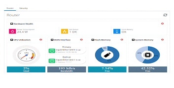
Hardware Health section shows the total Power Consumption of the router, Number of Fans on the system and their status, CPU Temperature and Battery health. If the router does not expose its hardware information, then this section will not be visible in the UI.
If Primary and Backup WAN Interfaces are configured, then the status of the same is displayed along with the interface Name. The status is shown in green only when both admin and operational status are up. This also shows the amount of traffic flowing through WAN Interfaces.
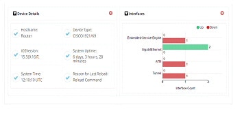
Device Details section shows Hostname, Device Type, IOS Version, System Uptime from last reload, Current system time and the Reason for last reload of the router. The reason for last reload could be the normal reload by executing reload command to restart the router, power on or system crash etc.
Interfaces chart groups the Interfaces by type and shows the number of interfaces that are up and down. If the user moves the cursor over the chart, then the specific interfaces will be displayed as tooltip.
Step 2 To update the charts, click on the refresh button given at the top of the charts section.
Security Dashboard
To view the security dashboard view, perform these steps:
Step 1 Click on Dashboard> Security to open the Security dashboard view.
Figure 44 Security Dashboard (Dashlets displayed are Top 10 Applications and Top Users)
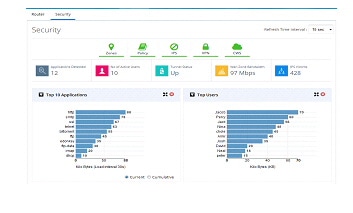
Figure 45 Security Dashboard (Dashlets displayed are VPN, Policy, Top 10 Threats and IPS Drilldown)
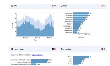
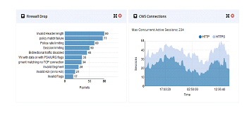
Figure 46 Security Dashboard (Dashlets displayed are Firewall Drop and CWS Connections)
The top portion shows the security features enabled on the device. The green icon indicates they are enabled. User can click on a specific icon and navigate to that feature. If any security feature is not enabled, then the relevant charts are not visible. They will be minimized and shown in the tray above the pane which is showing the security features ennoblement status. To close any chart click on the close button of the chart and the chart will be minimized into the tray. The icons can be clicked to enable it again.
- Applications Detected—total number of Application protocols discovered by NBAR. While moving the mouse over, the list of applications will be displayed.
- Number of Active Users —top users contributing to the traffic currently traversing the device
- Tunnel Status—if VPN is configured, then this indicates the status of the Tunnel
- WAN Zone Bandwidth—traffic going through the WAN Interfaces
- IPS Victims—total number of users impacted by some attack. The information is obtained by enabling the IPS feature
Following is the list of various charts supported to show the security information and bandwidth consumption statistics of the network. These charts will update periodically. The refresh interval can be modified.
- Top Applications—This dashboard will list the top 10 application protocols contributing to the traffic through the router in terms of bandwidth consumption at any point of time. This chart will also provide the cumulative bandwidth consumption of the device from the time of router reload. CCP Express will get the update from device at configured regular intervals.
- Top Users—This dashboard will list the top users in the router in terms of bandwidth consumption at any point of time. It supports both current bandwidth consumption.
- VPN—VPN chart shows encrypted and decrypted traffic through the configured VPN tunnel.
- Policy—Policy chart shows the amount of data that matched a specific Firewall Policy configured on the device. This gives the snapshot view of which policy is hit the most in the network.
- Top Threats—This dashboard shows the Top 10 threats in the network in terms of malicious packets.
- IPS Drilldown—This dashboard shows the total attacks made by the attackers and attacks received by the victims.
- Firewall drop—This dashboard shows the Top 10 firewall drops and the cause of the drops.
Application Visibility and Control Dashboard
To view the AVC dashboard, perform these steps:
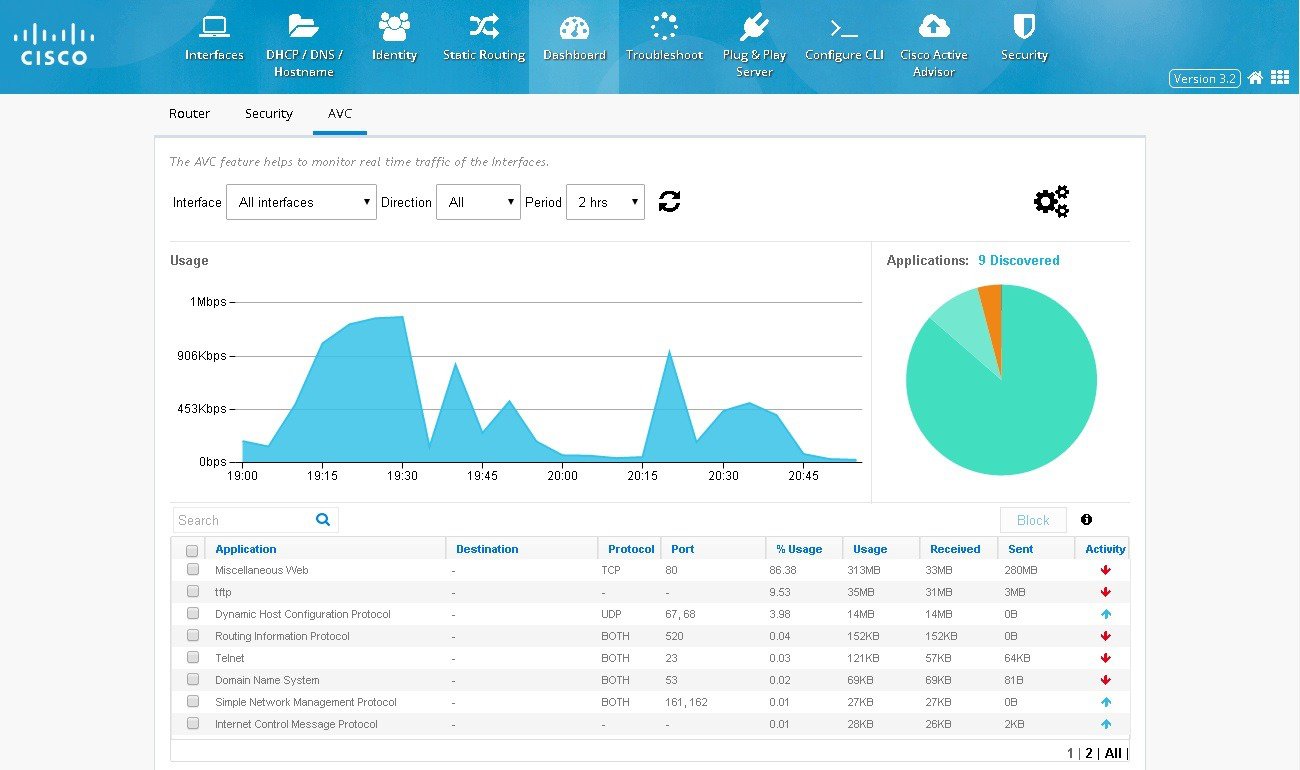
Step 1 Click Dashboard> AVC to open the AVC dashboard view.
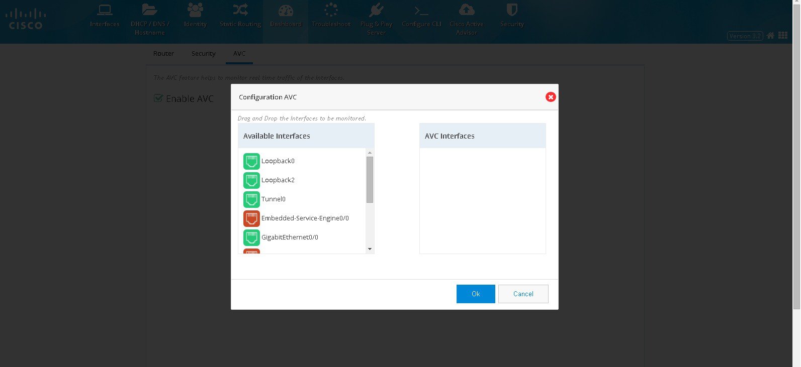
Step 2 Enable AVC, a screen appears where you can drag and drop the interfaces to AVC interfaces.
Step 3 Click OK. Figure 48 displays. This page displays all the applications and the relevant data. At a time 8 applications are listed in the page. You can filter applications using the search option.
Step 4 You can also click Settings icon to add or remove interfaces for AVC.
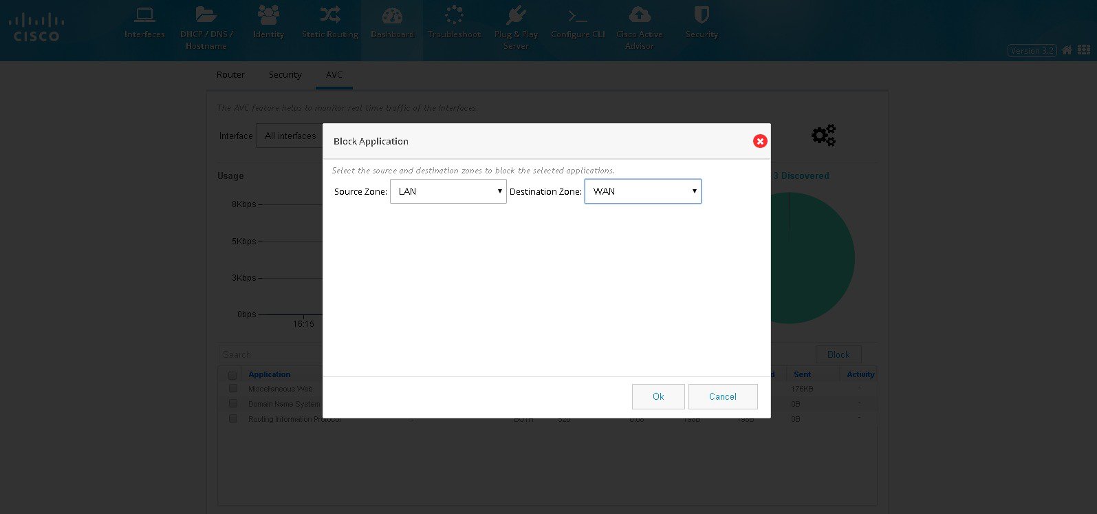
Step 5 If security is enabled, you can block the applications in AVC screen. Select the applications and click BLOCK. Select the Source and Destination Zone and click OK. (Figure 49). Selected application will be blocked. When an application is blocked, a policy is automatically created by the name avc-app-block-1. The subsequent blocking of applications will add policies with the same name format with only the numbering incremented.
Figure 49 Blocking Applications
Security Features
This section includes the following:
Note Some of the 800 series models doesn’t support IPS and you may not get an option to configure IPS.
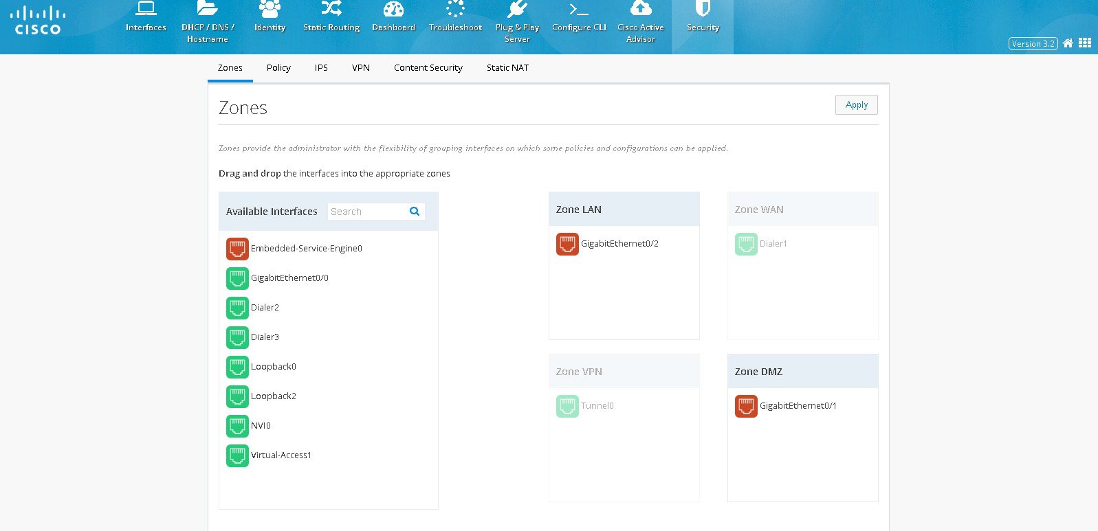
Zones
Zones establish the security borders of your network. A zone defines a boundary where traffic is subjected to policy restrictions as it crosses to another region of your network. ZFW’s default policy between zones is deny all. If no policy is explicitly configured, all traffic moving between zones is blocked.
- Click Security > Zones. The left side list shows the list of available interfaces which can be moved to appropriate security zones. The supported zones are WAN, LAN, VPN, and DMZ.
- If any interface needs to be moved to any security zone, it can be just dragged and dropped into the zone. WAN and VPN zones are grayed out here and moving the WAN interface under WAN zone can be done in interface screen. Also when VPN is configured, the respective Tunnel interface will be moved to VPN zone internally.
Policy
With the Zones and Policy pages configured, users can enable Zone based Firewall on the device. Policy page applies user-defined rules or policy on the traffic that flows between source and destination zones. The source and destination zones are tied together to make a zone pair under which the policy is applied. Prior to creating and applying policy, user needs to configure and assign the interfaces under the right zones.
Policy feature provides more granularity in identifying and filtering the traffic. Within the traffic between source zone and destination zone, the user can filter the traffic further based on the source and destination network, application type, the source and destination ports, domains, and the user groups.
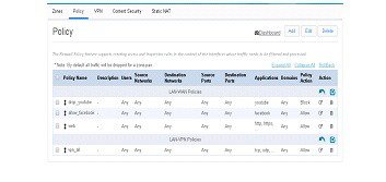
Policy Summary
To view the policy summary, perform these steps:
Step 1 Click Security >Policy to display the summary screen of Policy. The summary screen lists all existing policies and option to add, edit and delete an existing policy
– The Policy display in the summary screen is based on the zone pairs. For e.g in the picture below there are two groups of policies and the groups based on zone pairs viz. LAN-WAN and LAN-VPN
– The order of policies can be changed by just dragging and dropping the policies within the zone pair section table. The changes can be reverted by clicking the arrow icon placed on top of the zone pair section
Block a specific Application
To block a specific application, perform these steps:
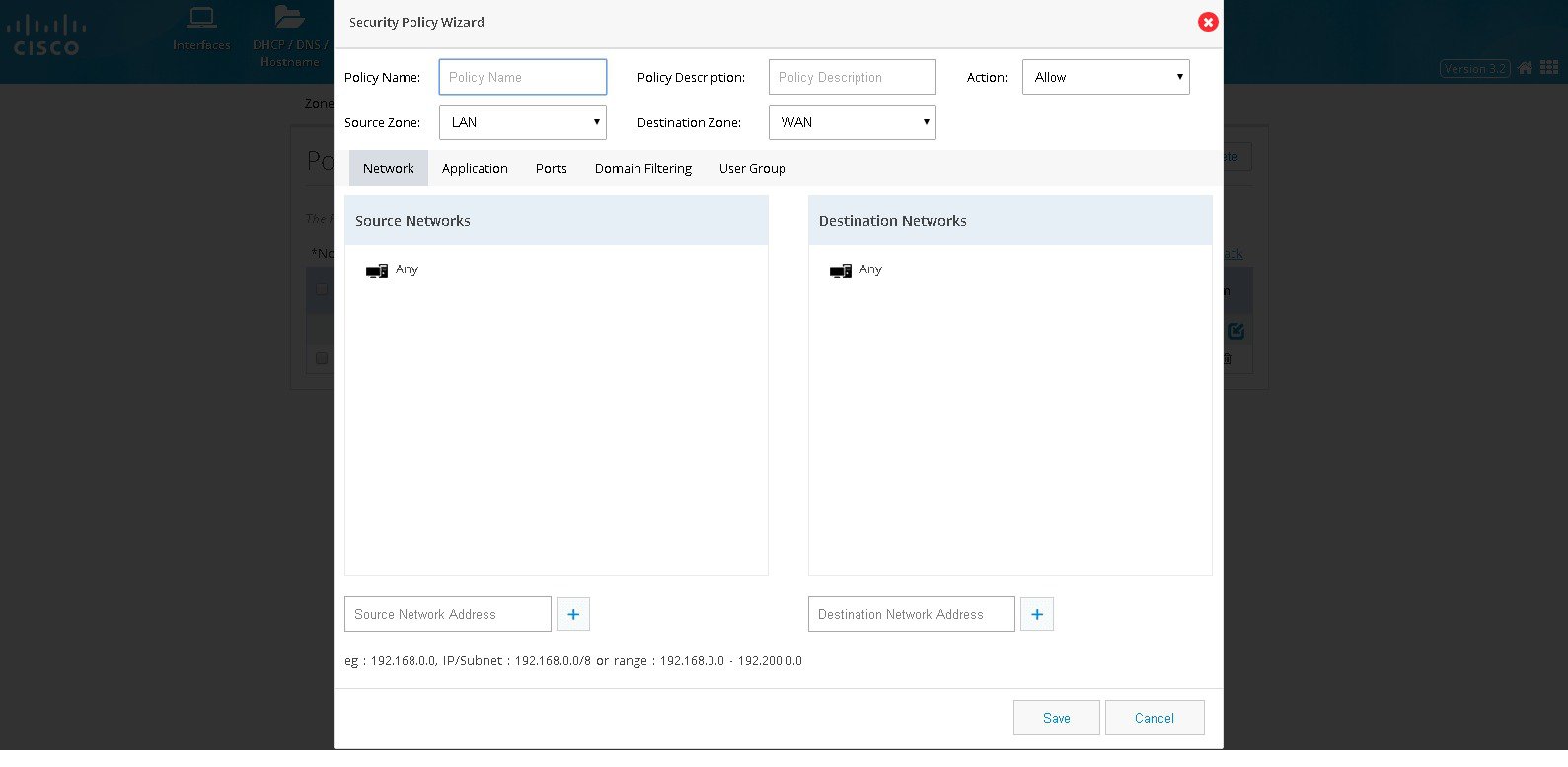
Step 1 Click Security > Policy, and click Add. The Policy Dialog appears.
Step 2 From the Policy Dialog, provide Policy Name, description, and the source and destination zones whose traffic needs to be processed. Also, the action needs to be taken on the selected traffic whether we need to block it or allow it.
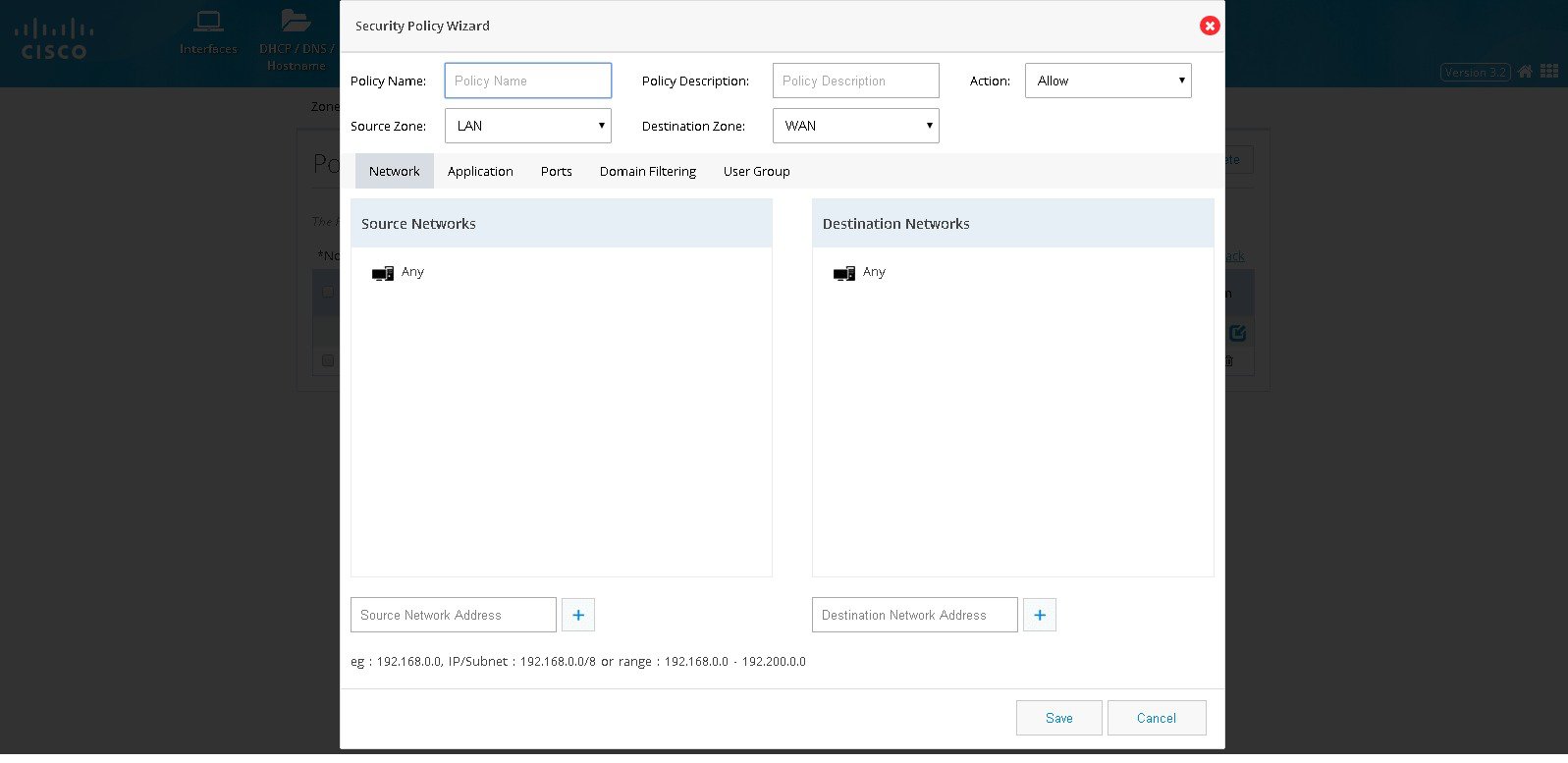
Step 3 Click Network. Add source and destination network if any specific network within the zone-pair is to be handled. Add the source network by specifying the network in the textfield and add plus button. The same procedure needs to be followed for any destination network as well. By default, source and destination network would be ‘any’.(Figure 52)
Figure 52 The Security Policy Wizard (Landing screen with Network tab contents)
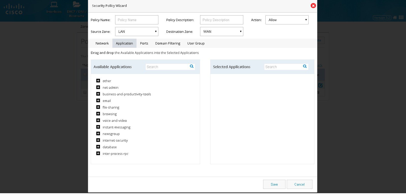
Step 4 Click Application to select the application to be inspected or blocked. The Available Applications shows the list of applications grouped as per the known category. The needed application or group can be dragged and dropped in the Selected Applications list.
Figure 53 The Security Policy Wizard (Application tab contents)
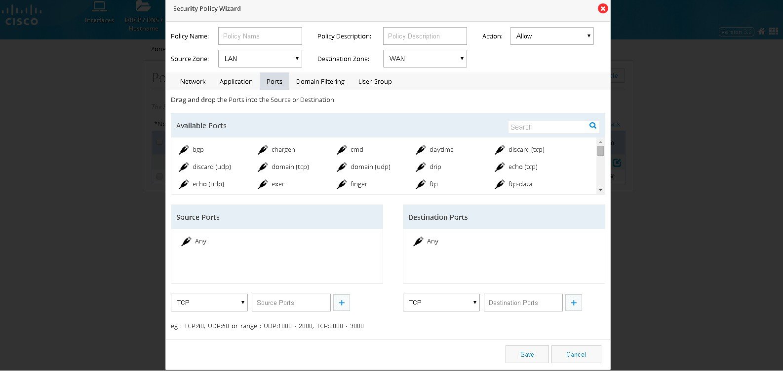
Step 5 Click Ports if it is required to classify the application based on source and destination ports. By default, traffic originating from any ports of the selected networks will be processed. User can add a required source and destination ports. List of popular applications is given based on their Category and by dragging and dropping the needed one will handle the port specific to that.
Figure 54 The Security Policy Wizard (Ports tab contents)
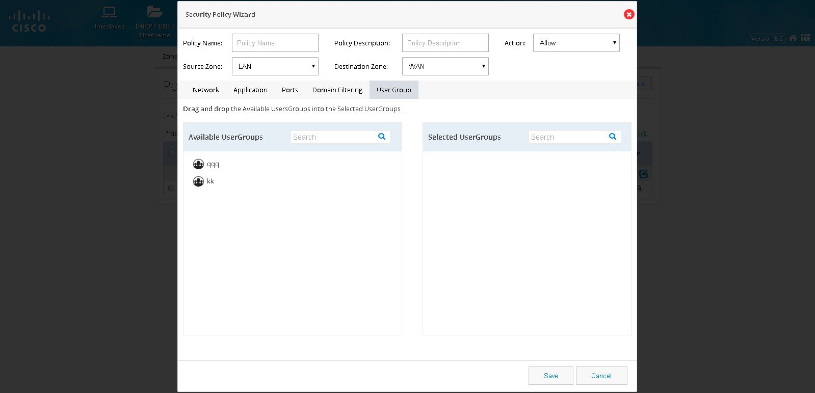
Step 6 Click User Groups if the traffic filtering is to be handled based on the user or group originating the traffic.
Figure 55 The Security Policy Wizard (User group tab contents)
Block a specific Domain
To block a specific domain, perform these steps:
Step 1 Click Security > Policy, and click Add.
Step 2 Policy Dialog will appear. Provide Policy Name, description, and the source and destination zones whose traffic needs to be processed. Also the action needs to be taken on the selected traffic whether we need to block it or allow it.
Step 3 Click Network. Add source and destination network if any specific network within the zone-pair is to be handled. Add the source network by specifying the network in the text field and add plus button. The same procedure needs to be followed for any destination network as well. By default all the networks in the Zone pair is processed.
Figure 56 The Security Policy Wizard (Landing screen with Network tab contents)
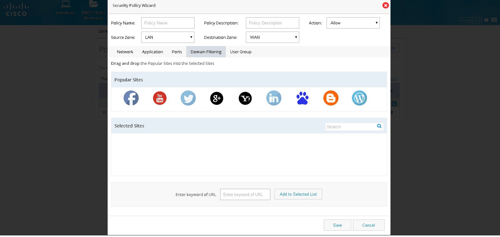
Step 4 Click Domain Filtering and the screen shows list of popular sites. User can drag and drop if any of the popular websites need to be blocked. If any unlisted domain needs to be added that URL (wild card pattern accepted) can be given in the text box.
Figure 57 The Security Policy Wizard (Domain Filtering tab contents)
Step 5 Click User Groups if the traffic filtering is to be handled based on the user or group originating the traffic.
Note To select the specific User group it should have been already added through the Identity feature.
IPS
Cisco IOS Intrusion Prevention System (IPS) is an inline, deep-packet inspection feature that effectively mitigates a wide range of network attacks. A component of the Cisco IOS Integrated Threat Control framework and complemented by Cisco IOS Flexible Packet Matching feature, Cisco IOS IPS provides your network with the intelligence to accurately identify, classify, and stop or block malicious traffic in real time.
To use the IPS feature, the following conditions are to be met:
- IPS Signature Packages should be present on the router under flash:
- Security License should have been enabled on the router
- WAN interface configuration should have been completed
If these conditions are not met, then respective error message will be displayed when IPS feature is accessed.
Note Some of the 800 series models doesn’t support IPS and you may not get an option to configure IPS.
Enabling IPS
If all the prerequisites are met, then user gets the option to enable IPS. To enable IPS, perform these steps:
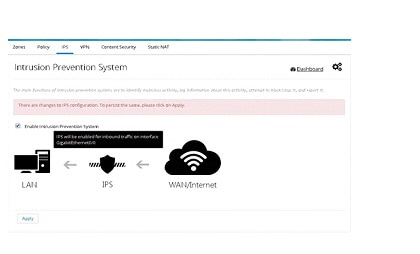
Step 1 Click Security > IPS, and choose the Enable IPS check box.
Step 2 When you enable IPS for the first time, a popup with the list of all the IPS Signature Packages is available on the box, with the first one selected by default. Even if there is only a single package, you get this dialog box.
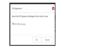
Step 3 Select appropriate one and click OK.
Step 4 You get the message that there are changes to IPS configuration. Upon applying the changes, IPS will be enabled on inbound traffic (depicted in the image below the checkbox). The selected signature package - User is given the message that there are changes to IPS configuration. Upon applying the changes, IPS will be enabled on inbound traffic (depicted in the image below the check box). The selected signature package will be compiled and applied too. To view the interface(s) on which this will be applied, hover on the image to view the tool tip containing that information.
Figure 59 Intrusion Prevention System Page
Step 5 Click on the Apply button to persist changes. You have to wait for a minute (depending on the signatures selected) as the signature compilation is happening in the background.
Step 6 After the settings are applied and signature compilation done, user is presented with the IPS screen with the information on the package version and count of failed signatures (if any).
Note For all further disable/enable cycles, you will not be prompted to select the package. In those cycles, after enabling, you get a message that “Signature compilation is in progress”. You can choose to visit other pages and come back later or to hit “Refresh” button after a while to see the IPS settings screen.
Uploading IPS Signature Packages
You have the option to upload signature packages onto the router at any point in time. To upload IPS signature packages, perform these steps:
Step 1 Hover your cursor over the Configure icon that is available on the right pane. The settings menu appears.
Step 2 Click on the Upload IPS Signature Packages option. A dialog box appears.
Step 3 Click on the Folder button and select the file from the file selection dialog box and click OK.
Step 4 CCP Express validates for the file name, duplication and free space on the router. If any of these validations fail, appropriate error message will be displayed. If the file validations are through, user gets the message that file is ready for upload and the “Upload” button is enabled. User has to click on the Upload button to initiate the upload.
Step 5 Upload takes a while as the file size is around 20MB. Once upload is done, the same is intimated to the user. User can proceed with uploading more files or quit the dialog.
Changing IPS Signature Packages
When IPS is enabled, if the box has more than one Signature Package file, user is provided with an option to change the signature package. To change IPS signature packages, perform these steps:
Step 1 Hover your cursor over the Configure icon that is available on the right pane. The settings menu appears.
Step 2 Click on the Change IPS Signature Packages option. A dialog box with the list of available packages on the box is displayed. The currently selected one is listed, but selection is disabled for this one. The packages are sorted in reverse alphabetical order to have the latest one at the top for easy selection.
Step 3 Select the package of your choice and click OK. Signature compilation may take several seconds.
Step 4 After the settings are applied and signature compilation done, user is presented with the IPS screen with the information on the newly selected package version and count of failed signatures (if any).
Download link for IPS Signature Packages
You can download the relevant signature package files from the link that is shared with you. This is a link that connects you to an internal CISCO page. To download IPS signature package, perform these steps:
Step 1 Hover your cursor over the Configure icon that is available on the right pane. The settings menu appears.
Step 2 Click on the Download IPS Signature Packages option. Upon clicking on the link, you will be taken to the CISCO IPS Services page (external to CCP Express), from where the you can download signature packages that is needed.
Enabling/Disabling Notifications/Log
User is provided with links to enable/disable SDEE and syslog notifications. The menu is smart to toggle between the enable/disable options for each based on the setting in the system.
SDEE Notifications
To enable SDEE notifications, perform these steps:
Step 1 Hover mouse on the Configure icon that is available on the right pane. The settings menu appears.
Step 2 Click on the Enable SDEE Notifications option.
Step 3 After the setting is applied, the menu item changes to Disable SDEE Notifications. This is because in the device, it is enabled. If you click on this option again, it will toggle the state on the device as well as on the menu.
Syslog
To enable syslog, perform these steps:
Step 1 Hover your cursor over the Configure icon that is available on the right pane. The settings menu appears.
Step 2 Click on the Enable Syslog option.
Step 3 After the setting is applied, the menu item changes to Disable Syslog. This is because in the device, it is enabled. If you click on this option again, it will toggle the state on the box as well as on the menu.
Note Enabling IPS feature for the first time in router may take several seconds. When we try Chrome to configure IPS for the first time, we may encounter message like UI is unresponsive. This message will go away once IPS is enabled.
VPN
CCP Express supports creation of Site-to-Site VPN configuration and DMVPN spoke side configuration.
Primary WAN interface has to be configured and that should be part of WAN Zone and also LAN interfaces should be part of LAN Zone before configuring any VPN.
IPSec Multi-Site Configuration
To configure multi-site VPN, perform these steps:
Step 1 Click Security > VPN and select IPsec option from the VPN Configuration drop-down list.
Step 2 Click Enable VPN check box and click Add Site.
Step 3 Provide Tunnel IP and Mask for the site being configured.
Step 4 Provide the remote peer address (WAN IP address of the other end).
Step 5 Select an appropriate Key Exchange model (either IKEv1 or IKEv2). By default, IKEv2 is selected and that is recommended.
Step 6 Provide Pre shared Key.
Step 7 Provide the Remote IP addresses which are allowed to be accessed through the VPN tunnel.
Step 8 By default, from configuring site end, all the LAN side networks are allowed to access the other end through VPN Tunnel.
Figure 60 Site to Site Configuration
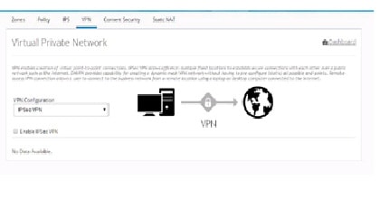
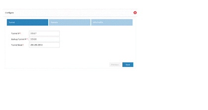
Figure 62 Site Configuration (Continued)
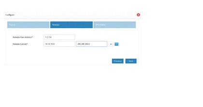
Figure 63 Site Configuration (Complete)
Step 9 After the configuration is complete, the list of sites are displayed. The user can choose to add more or delete sites from the available list.
Note If CCP Express is used to configure the Multi-Site VPN, ensure that both the ends are configured with CCP Express only. CCP Express internally uses the transform set as esp-aes, esp-sha-hmac and IKEv2 Proposal with encryption as 3des, integrity as md5 and Diffie Helman group as 2.
DMVPN Spoke Configuration
To configure DMVPN spoke configuration, perform these steps:
Step 1 Click Security > VPN and select DMVPN Spoke option from the VPN Configuration drop-down list.
Step 2 Click Enable VPN Check box.
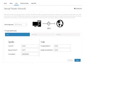
Step 3 Provide Tunnel IP and Mask for site being configured
Step 4 Provide the remote peer address (WAN IP address of the other end)
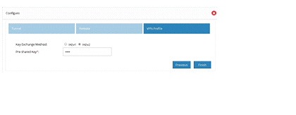
Step 5 Select an appropriate key exchange model (either IKEv1 or IKEv2). By default, IKEv2 is selected and that is recommended.
Step 7 Provide the Remote IP address which are allowed to be accessed through the VPN tunnel
Step 8 By default, from configuring site end, all the LAN side networks are allowed to access the other end through VPN Tunnel.
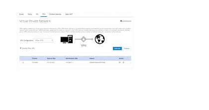
Figure 65 Virtual Private Network Page
Tunnel Status: When the DMVPN Spoke configuration is successful, the Hub is configured and active, then the Tunnel will come up between Hub and Spoke.
Figure 66 Virtual Private Network Page
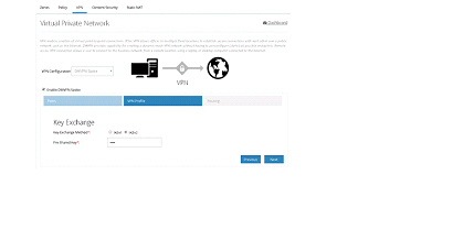
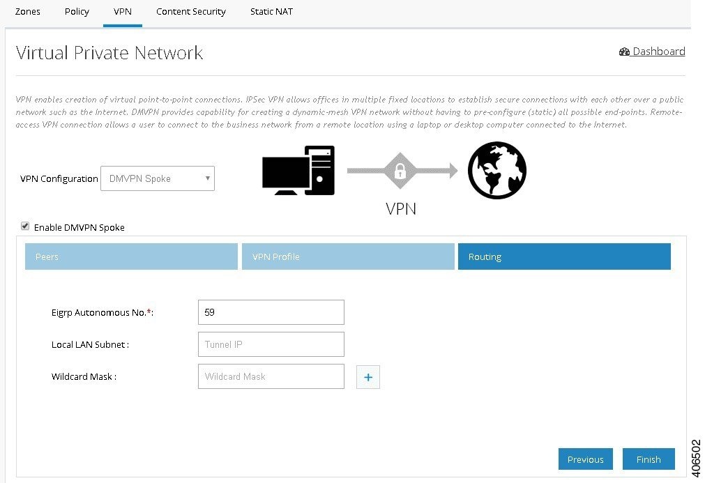
Figure 67 DMVPN Spoke Configuration (Routing)
DMVPN Hub Configuration
To configure DMVPN Hub, perform these steps:
Step 1 Click Security > VPN and select DMVPN Hub option from the VPN Configuration drop-down list.
Step 2 Click Enable VPN Check box.
Step 3 Provide Tunnel IP and Mask for site being configured
Step 4 Select an appropriate Key Exchange model (either IKEv1 or IKEv2). By default, IKEv2 is selected and that is recommended. Also, provide the pre-shared key.
Step 5 Provide the routing configuration.
Figure 68 DMVPN Hub Configuration
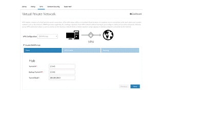
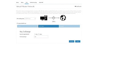
Figure 70 DMVPN Hub – Routing Configuration
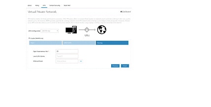
Remote Access VPN Configuration
To configure Remote Access VPN, perform these steps:
Step 1 Click Security > VPN and select Remote Access VPN option.
Step 2 Click Enable Remote Access VPN check box.
Step 3 Provide Pool Name and the range of IP Addresses for the pool.
Step 4 Provide the pre-shared key and select the crypto map interface.
Figure 71 Remote Access VPN Configuration
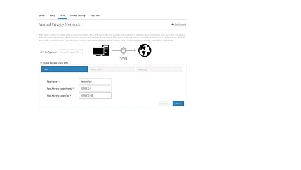

Figure 73 Remote Access VPN – Routing Configuration

Note By default, Remote Access VPN configuration supports only IKEv1 Key Exchange model and IP Sec enabled L2TP protocol.
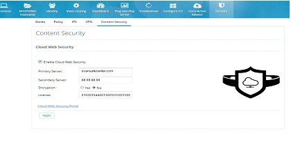
Content Security
Cloud based 'Security as a Service’ (SecaaS) such as Cloud Web Security (CWS) is a scalable means to provide market-leading web security to quickly and easily protect the network from web-based threats, such as Malware, while saving bandwidth, money, and resources. CWS provides Anti-X functionality (anti-malware, anti-bot, anti-virus, and anti-phishing) on ISR-G2 itself without the need for expensive Security Appliances in branch, small offices.
To configure content security, perform these steps:
Step 1 Click Security > Content Security.
Step 2 Provide Primary CWS Server IP address or DNS resolvable hostname and Secondary server information.
Step 3 Provide the license key received from CWS service provider and specify if it is an encrypted or unencrypted key.
Figure 74 Content Security Page
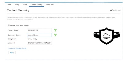
Edit Content Security
After CWS is fully configured and the tower is reachable, it will be indicated by green tower icon as shown in the screen below. otherwise, it will be displayed in red.
Figure 75 Content Security Page
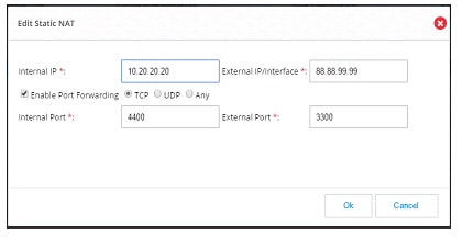
Static NAT
Static NAT creates a fixed translation of unregistered real address to mapped registered address. Also with port forwarding option, it is possible to open ports in response to inbound traffic for a specified service. To create a static NAT, perform these steps:
Step 1 Click Security > Static NAT. To add a Static NAT, click Add. A dialog box opens.
Step 2 Provide the Internal IP address which needs to be translated and external IP address or Interface.
Step 3 If you need to send the traffic to specific port, then click Enable Port Forwarding check box, and select the type of port like TCP or UDP. If the port type is not known select Any option which will support both the type of ports.
Step 4 After selecting the ports, specify internal and external ports.
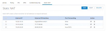
Figure 77 Edit Static NAT Page
Identity
Identity awareness is a key requirement for any Security solution. It is defined as the ability of the device to be aware of end-user identities. Also this supports User and Group management that allows administration of user authentication and authorization profiles using either local or external service.
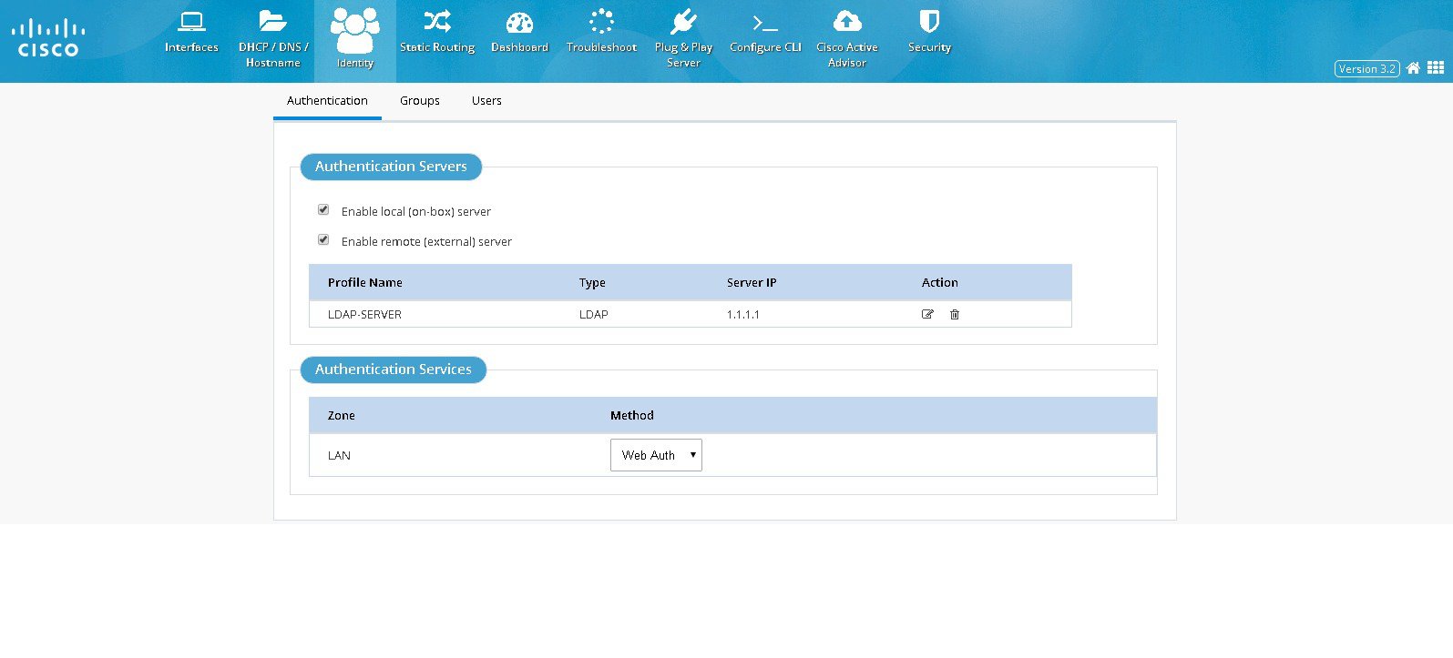
Authentication Servers / Services
Authentication section will have following options to configure Authentication feature:
Configuring Authentication Servers
– User is given an option to select the Authentication servers under two categories. It can be either an on-box server option means router itself acts as the local authentication server or remote servers.
– For remote server option, Active Directory alone is supported
– User can choose to configure both the server options. If both are configured then authentication attempt will first happen with remote server and if remote server is not reachable then it may fall back to local
Configuring Authentication Services or Methods
– The supported Authentication Services will be NTLM or Thebault based
– The authentication method can be chosen for different zones and but in the current release only LAN zone is supported. If LAN Zone is configured all interfaces coming under LAN zone will be configured accordingly.NTLM option is supported only for remote server option. If the user configures both on-box option and remote server then selecting NTLM option will not be allowed.
To configure authentication, perform these steps:
Step 1 Click Identity > Authentication. In Authentication Servers section, select the local or remote option
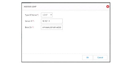
Step 2 If remote option is selected then “Add new Server” option appears.
Step 3 Click Add new Server and a dialogue will appear where the details of LDAP server like IP address of the server and Base DN information can be entered.
Managing User Groups
Steps to create or delete user groups or to see the list of created user groups are listed below:
Step 1 Click Identity > Groups. It will list all available groups.
Step 2 Click Add. Enter the user name in the popup.
Step 3 Enter the group name to be created.
Figure 80 Group Management Page
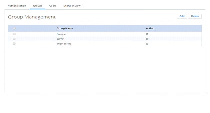
Step 4 To delete any group, select the checkbox and click on Delete and confirm.
Managing Users
Steps to create a new user and associate/dissociate a user with a group are listed below:
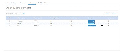
Step 1 Click Identity > Users. Click Identity > Users. All created user names will be listed. (Figure 81)
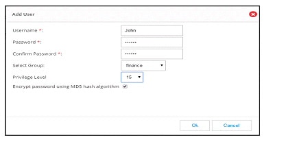
Step 2 Click Add. The add user popup will be displayed.
Step 3 Enter the user details and submit.
Step 4 Please avoid doing this if it is the logged in user as in the background it needs to delete the user and recreate.
Figure 81 User Management Page
Static Routing
The Static Routing feature allows you to add, edit, and delete IP routes to a destination interface, or IP address from your IPv4 or IPv6 subnets.
Creating a Static Route
To create a static route, perform these steps:
Step 1 Click Static Routing to open the Static Routing page.
Figure 83 The Static Routing page
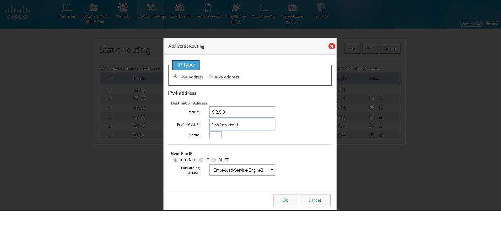
Step 2 Click Add to open the Add Static Routing dialog box with options to specify an IPv4 or IPv6 static route.
Step 3 Based on whether the IP address is an IPv4 or IPv6 address, select the IPv4 or IPv6 tab, and specify the following:
- Destination address: specify the prefix and prefix mask for your IPv4 or IPv6 address
- Next Hop IP:
If you select Interface as the next hop IP, select the forwarding interface from the drop-down list.
If you select IP as the next hop IP, specify the Next Hop IP that must be used.
You can also specify DHCP address.Step 4 Click OK to add the static route.
Editing a Static Route
To edit an existing static route, perform these steps:
Step 1 Click Static Routing to open the Static Routing page.
Step 2 From the list of static routes, select the static route you want to edit, and click Edit.
The Edit Static Routing page is displayed.Step 3 Specify these fields for your static route:
Step 4 Click OK to edit the static route.
Deleting a Static Route
To delete a static route, perform these steps:
Step 1 Click Static Routing to open the Static Routing page.
Step 2 From the list of static routes, select the static route you want to delete and click Delete.
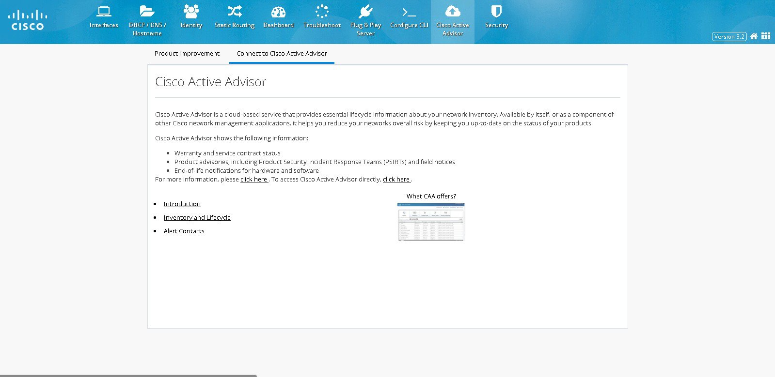
Cisco Active Advisor
The Cisco Active Advisor feature provides the essential life cycle information about your network inventory. Cisco Active Advisor also helps to reduce network’s overall risks by updating the status of the products in the network periodically. Cisco Active Advisor shows the following information:
Uploading the Configuration
To upload the router configuration, perform these steps:
Step 1 Click Cisco Active Advisor to open Cisco Active Advisor page.
Step 2 Enter your CEC username and password in the Product Improvement tab
Figure 84 Product Improvement tab
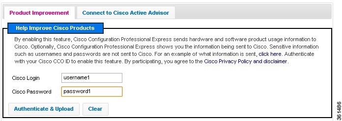
Step 3 Click Authenticate & Upload .
Viewing the Device Details
Step 1 Click Connect to Cisco Active Advisor tab,
Step 2 Click Inventory and Lifecycle to view the device details.
Figure 85 Connect to Cisco Active Advisor tab
Configuring WAN for Cisco 800M Series Routers
This section explains how to set up WAN primary and back up links for Cisco 800M series routers with Wired LAN access.
Setting Up 3G GSM WAN Primary Uplink
To set up a 3G GSM WAN primary uplink, perform these steps:
Step 1 Click Interfaces to open the Interfaces page.
Step 2 Select the 3G Interface you want to configure and click Edit .The Edit Cellular Configuration page is displayed.
Figure 86 Cellular WAN Interface Configuration
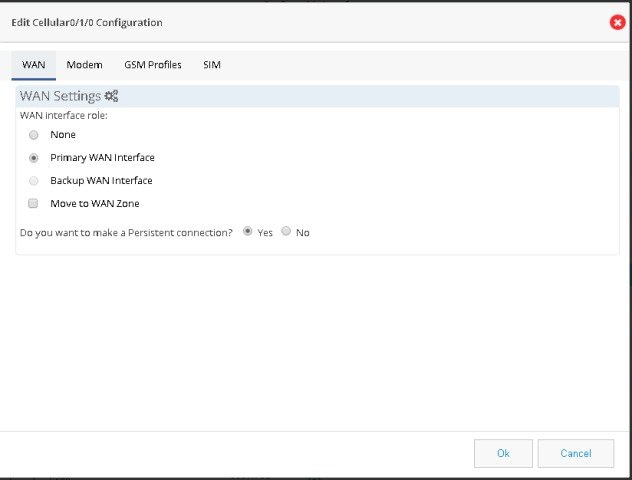
Step 3 From the WAN tab, select Primary WAN Interface. If the device supports security features then “Move to WAN Zone” appears and user can add the WAN interface as part of WAN Zone. It is a mandatory requirement for many security features to have WAN interface as part of WAN Zone.
Step 4 If you want to establish a persistent connection to your service provider from the Dialer interface, select YES . By default, this is set to NO to disable persistent connection.
Step 5 Modem firmware is activated by default. If you want to change the default modem firmware, from the Modem tab, activate the corresponding modem firmware.
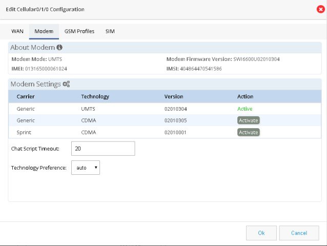
Step 6 Specify the Chat Script Timeout value.
Step 7 Specify the technology preference as GSM. Technology preference is specific to the firmware and GSM will be available only if the selected firmware is UMTS. Default value is Auto.
Step 8 From GSM profile tab, click Add to create GSM profile. GSM profile tab will be visible only if the selected firmware is UMTS.
Figure 88 GSM Profile Configuration
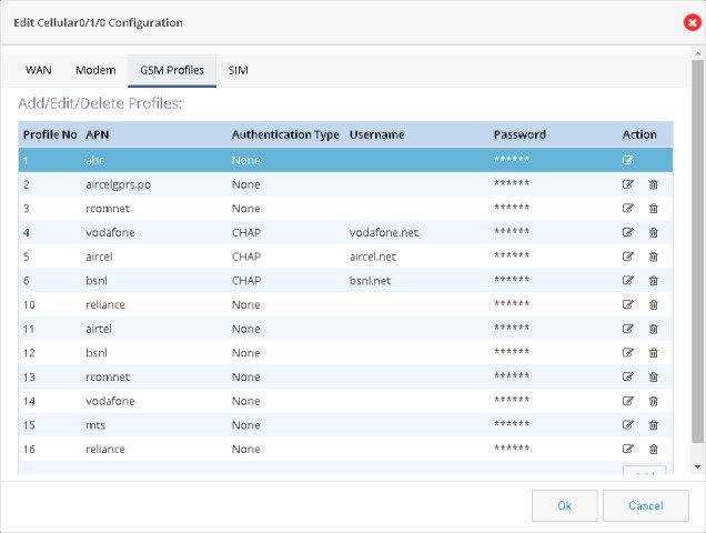
Step 9 Specify the access point name (APN) provided by your service provider.
Step 10 Select the Authentication method. This can either be PAP or CHAP.
Step 11 Specify the username and password provided by the service provider.
Step 12 Click Save to save the changes.
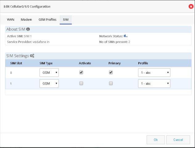
Step 13 From SIM tab, select the SIM type as GSM and activate the SIM.
Setting Up 3G CDMA WAN Primary Uplink
To set up a 3G CDMA WAN primary uplink, perform these steps:
Step 1 Click Interfaces to open the Interfaces page.
Step 2 Select the 3G Interface you want to configure and click Edit .The Edit Cellular Configuration page is displayed.
Figure 90 CDMA Cellular WAN Interface Configuration
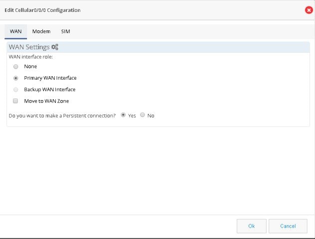
Step 3 From the WAN tab, select Primary WAN Interface. If the device supports security features then “Move to WAN Zone” appears and user can add the WAN interface as part of WAN Zone. It is a mandatory requirement for many security features to have WAN interface as part of WAN Zone.
Step 4 Modem firmware is activated by default. From the Modem tab, activate the corresponding modem firmware if you want to change the default modem firmware.
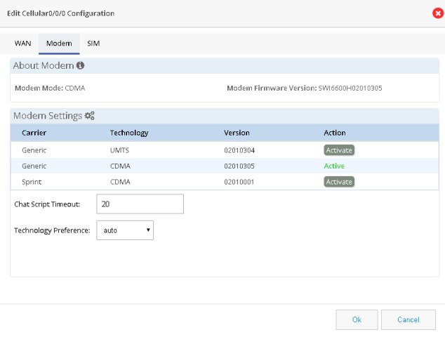
Step 5 Specify the waiting time for Chat Script Timeout.
Step 6 Specify the technology preference as CDMA. Default value is Auto.
Step 7 From SIM tab, select the SIM type as CDMA and activate the SIM.
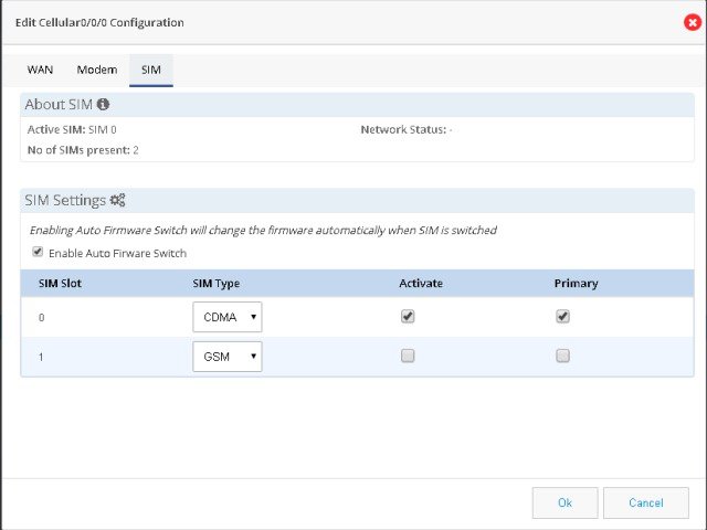
Setting Up Serial WAN Primary Uplink
Step 1 Click Interfaces to open the Interfaces page.
Step 2 Select the serial interface you want to configure and click Edit . The Edit Serial Interface Configuration page is displayed.
Step 3 Select Primary WAN Interface from Primary Secondary Interface tab and enter the SLA Configuration IP Address.
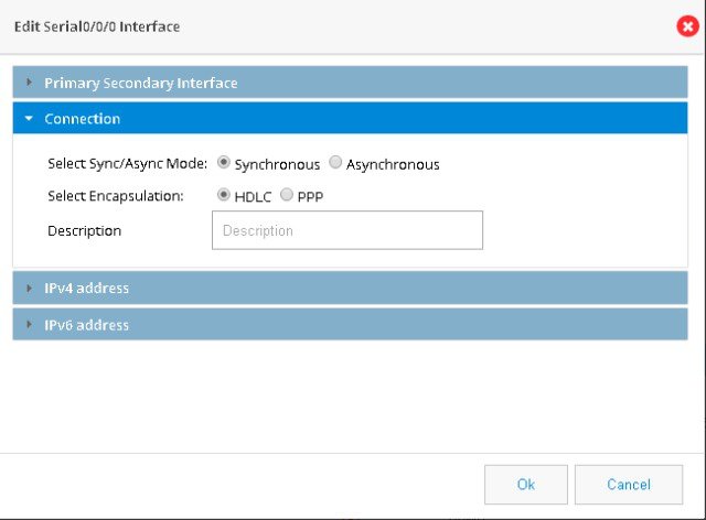
Step 4 From the Connection tab, select the required serial communication mode as synchronous or asynchronous. Specify the required serial encapsulation type. You can select HDLC or PPP encapsulations for synchronous mode and SLIP or PPP for asynchronous mode.
Figure 93 Serial WAN Interface Configuration
Step 5 Based on whether you are configuring an IPv4 or IPv6 address, select the appropriate tab. Specify the details for the IP address depending on whether the IP address is dynamically or statically assigned.
For configuring an IPv4 address:
This can be either Easy IP (IP Negotiated), Static IP Address, or No IP Address. By default, the IPv4 address is IP negotiated. There is an option to enable NAT configuration and the recommendation is to enable NAT for WAN interfaces. This will create NAT overloading configuration hence all LAN IPs are translated to public IP before being sent to WAN uplink.
For configuring an IPv6 address:
Select the IPv6 address type. The IPv6 address can be either AutoConfig, Use Prefix from Provider, Static IP Address, or No IP Address.
Setting Up Ethernet WAN Primary Uplink
Step 1 Click Interfaces to open the Interfaces page.
Step 2 Select the GigabitEthernet Interface you want to configure and click Edit . The Edit GigabitEthernet Configuration page is displayed.
Figure 94 GigabitEthernet Interface Configuration
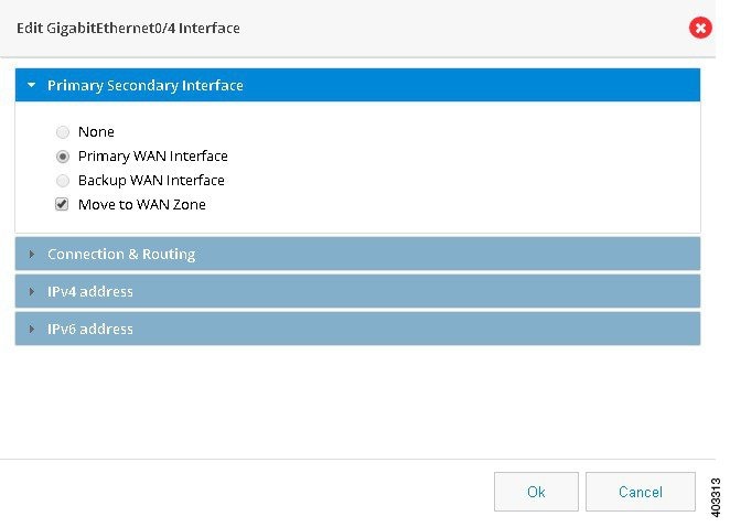
Step 3 Select Primary WAN Interface from Primary Secondary Interface tab.
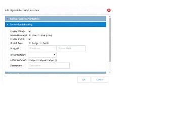
Step 4 From the Connection and Routing tab, check Enable PPPoE check box, and enter the description in the description field. For IPv4 Routed Protocol, you may configure Ipv6oE with options of Bridge or DHCP configuration.
Step 5 From the Connection tab, check Enable PPPoE check box, and enter the description in the Description field.
Step 6 Based on whether you are configuring an IPv4 or IPv6 address, select the appropriate tab. Specify the details for the IP address depending on whether the IP address is dynamically or statically assigned.
For configuring an IPv4 address:
This can be either Easy IP (IP Negotiated), Static IP Address, or No IP Address. By default, the IPv4 address is IP negotiated. There is an option to enable NAT configuration and the recommendation is to enable NAT for WAN interfaces. This will create NAT overloading configuration hence all LAN IPs are translated to public IP before being sent to WAN uplink.
For configuring an IPv6 address:
Select the IPv6 address type. The IPv6 address can be either AutoConfig, Use Prefix from Provider, Static IP Address, or No IP Address.
Step 7 From the Authentication tab, check CHAP or PAP check box and specify the username and password given by Service provider.
Step 8 Click OK to confirm the configuration.
Step 9 (Optional) Perform the steps in “Configuring a LAN with DHCP and VLANs” section to configure LAN.
Setting Up 3G GSM Back up WAN Uplink
To set up a 3G GSM back up WAN uplink, perform these steps:
Step 1 Click Interfaces to open the Interfaces page.
Step 2 Select the 3G Interface you want to configure and click Edit .The Edit Cellular Configuration page is displayed.
Step 3 From the WAN tab, select Backup WAN Interface. If the device supports security features then “Move to WAN Zone” appears and user can add the WAN interface as part of WAN Zone. It is a mandatory requirement for many security features to have WAN interface as part of WAN Zone
Step 4 If you want to establish a persistent connection to your service provider, from the Dialer interface, select YES . By default, this is set to NO to disable persistent connection.
Step 5 Modem firmware is activated by default. From the Modem tab, activate the corresponding modem firmware if you want to change the default modem firmware.
Step 6 Specify the waiting time for chat script timeout.
Step 7 Specify the technology preference as GSM. Default value is Auto.
Step 8 From GSM profile tab, click Add to create GSM profile.
Step 9 Specify the access point name (APN) provided by your service provider.
Step 10 Select the Authentication method. This can either be PAP or CHAP.
Step 11 Specify the username and password provided by the service provider.
Step 12 Click Save to save the changes.
Step 13 From SIM tab, select the SIM type as GSM and activate the required SIM.
Step 14 Select the primary SIM and the GSM profile.
Step 15 Click OK to confirm the configuration.
Setting Up 3G CDMA WAN Back Up Uplink
To set up a 3G CDMA WAN primary uplink, perform these steps:
Step 1 Click Interfaces to open the Interfaces page.
Step 2 Select the 3G Interface you want to configure and click Edit .The Edit Cellular Configuration page is displayed.
Step 3 From the WAN tab, select Backup WAN Interface. If the device supports security features then “Move to WAN Zone” appears and user can add the WAN interface as part of WAN Zone. It is a mandatory requirement for many security features to have WAN interface as part of WAN Zone.
Step 4 Modem firmware is activated by default. If you want to change the default modem firmware,, activate the corresponding modem firmware from the Modem tab.
Step 5 Specify the waiting time for chat script timeout.
Step 6 Specify the technology preference as CDMA. Default value is Auto.
Step 7 From SIM tab, select the SIM type as CDMA and activate the required SIM.
Step 8 Select the primary SIM.
Setting Up Serial WAN Back Up Uplink
Step 1 Click Interfaces to open the Interfaces page.
Step 2 Select the serial interface you want to configure and click Edit . The Edit Serial Configuration page is displayed.
Step 3 Select Backup WAN Interface from Primary Secondary Interface tab and enter the SLA Configuration IP Address.
Step 4 From the Connection tab, select the required serial communication mode as synchronous or asynchronous. Specify the required serial encapsulation type. You can select HDLC or PPP encapsulations for synchronous mode and SLIP or PPP for asynchronous mode.
Step 5 Based on whether you are configuring an IPv4 or IPv6 address, select the appropriate tab. Specify the details for the IP address depending on whether the IP address is dynamically or statically assigned.
For configuring an IPv4 address:
This can be either Easy IP (IP Negotiated), Static IP Address, or No IP Address. By default, the IPv4 address is IP negotiated. There is an option to enable NAT configuration and the recommendation is to enable NAT for WAN interfaces. This will create NAT overloading configuration hence all LAN IPs are translated to public IP before being sent to WAN uplink.
For configuring an IPv6 address:
Select the IPv6 address type. The IPv6 address can be either AutoConfig, Use Prefix from Provider, Static IP Address, or No IP Address.
Setting Up Ethernet WAN Back Up Uplink
Step 1 Click Interfaces to open the Interfaces page.
Step 2 Select the Gigabit Ethernet Interface you want to configure and click Edit . The Edit Configuration page is displayed
Step 3 Select Backup WAN Interface from Primary Secondary Interface tab.
Step 4 From the Connection and Routing tab, check Enable PPPoE check box, and enter the description in the description field. For IPv4 Routed Protocol, you may configure Ipv6oE with options of Bridge or DHCP configuration.
Step 5 From the Connection tab, check Enable PPPoE check box, and enter the description in the Description field.
Step 6 Based on whether you are configuring an IPv4 or IPv6 address, select the appropriate tab. Specify the details for the IP address depending on whether the IP address is dynamically or statically assigned.
For configuring an IPv4 address:
This can be either Easy IP (IP Negotiated), Static IP Address, or No IP Address. By default, the IPv4 address is IP negotiated. There is an option to enable NAT configuration and the recommendation is to enable NAT for WAN interfaces. This will create NAT overloading configuration hence all LAN IPs are translated to public IP before being sent to WAN uplink.
For configuring an IPv6 address:
Select the IPv6 address type. The IPv6 address can be either AutoConfig, Use Prefix from Provider, Static IP Address, or No IP Address.
Step 7 From the Authentication tab, check CHAP or PAP check box and specify the username and password given by Service provider.
Configuring a LAN with DHCP and VLANs
Perform the following steps to create a DHCP pool and configure VLANs.
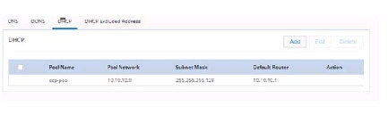
Step 1 Click DHCP/DNS to open the DHCP/DNS page. Move to DHCP Pool tab. (Figure 35).
Step 2 From the DHCP interface, click Add to create a new DHCP pool by specifying:
- Pool Name: the name of the DHCP pool
- Pool Network: the IP address of the subnet that represents all IP addresses allocated to the wired or wireless clients
- Import all DHCP options in to the DHCP server database: Check this check box to import all DHCP options into the DHCP server database. This ensures that the DNS is read from your service provider and is propagated to all DHCP clients.
Step 3 Click OK to create the DHCP pool.
Figure 95 Configuring a LAN with DHCP and VLAN
Step 4 Click Interfaces to open the Interfaces page.
Step 5 Click Add VLAN to open the Add VLAN dialog box and specify a unique ID for the VLAN being created.
Step 6 From the IPv4 address tab, choose Select from DHCP, and then select the DHCP pool from the drop-down list.This enables you to assign the IP addresses from the DHCP pool that is created.
Step 7 Click OK to confirm the configuration.
System Preferences
Currently the system preferences has only two option: Enable Usage Activity Collection and Cisco Recommended Security Settings. To configure the usage activity, follow the Steps:
Step 1 Click Options menu on the page header.
Step 2 Select Preferences. Preference page will be displayed. (Figure 96)
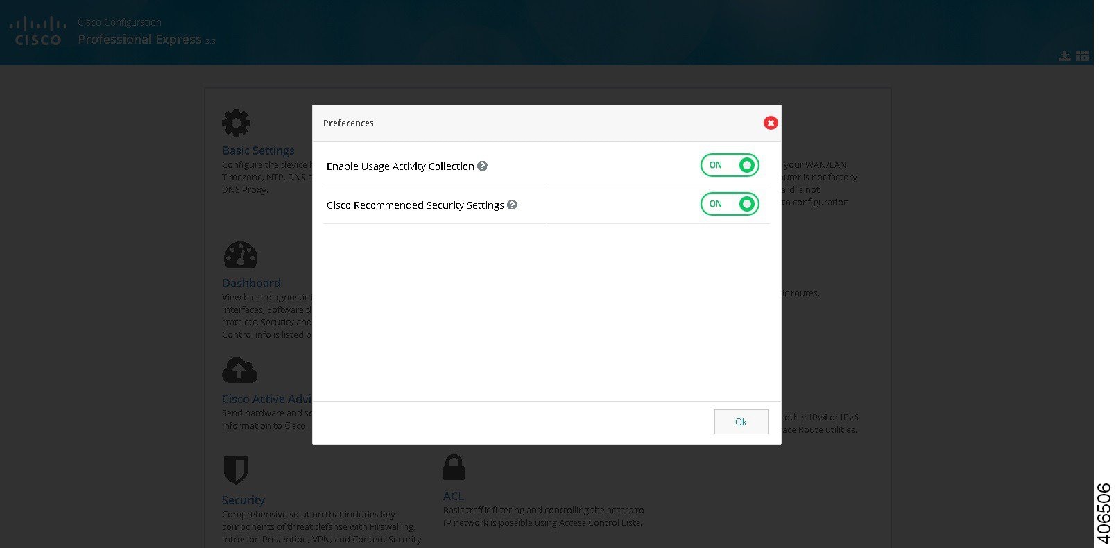
Step 3 If you want to enable/disable the options, then switch on or switch off the menu items.
Factory Reset
To load the router with default configuration, follow these step:
Step 1 Click on Options menu on the page header.
Step 2 Select Factory Reset. Factory Reset page will be displayed. (Figure 97)
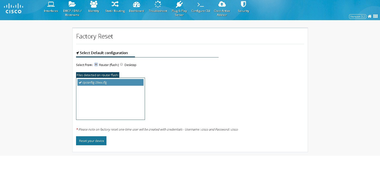
Step 3 If the existing default configuration is available in router, select ROUTER, or if it is available in your local PC, select Desktop, and select appropriate file.
Step 4 Click RESET YOUR DEVICE.
Step 5 Click YES to reset the device with default configuration. It takes time to reset the device and below page will be displayed. (Figure 98)
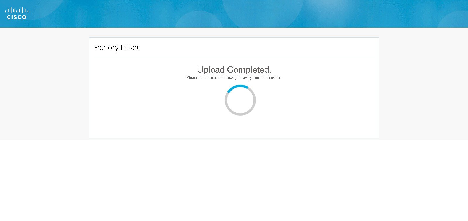
Step 6 After resetting the device, configure the router using Quick Setup Wizard.
Upgrade CCP Express
To upgrade the CCP Express, follow these steps:
Step 1 Click on Options menu on the page header.
Step 2 Select Upgrade option. The Upgrade CCP Express page is displayed. (Figure 99)
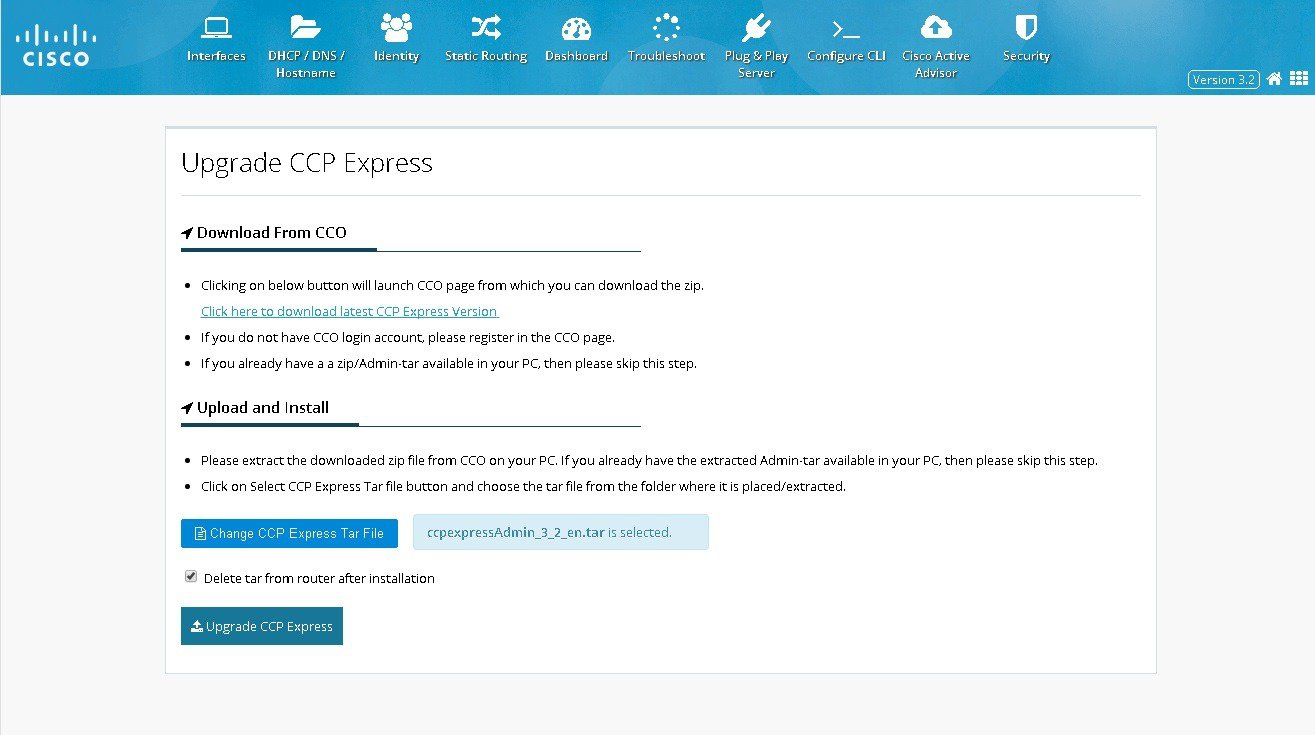
Step 3 Click on the link to download the latest CCP express version. It navigates to CCO page. If you do not have a CCO login, register it.
Step 4 If you already have a zip/Admin tar in your PC, skip the above step.
Step 5 Click on CCP Express Tar File and choose the tar file from the folder where it is extracted.
Step 6 After selecting the tar, click on Upgrade CCP Express and it asks for confirmation as shown. (Figure 100)
Figure 100 Upgrade Confirmation
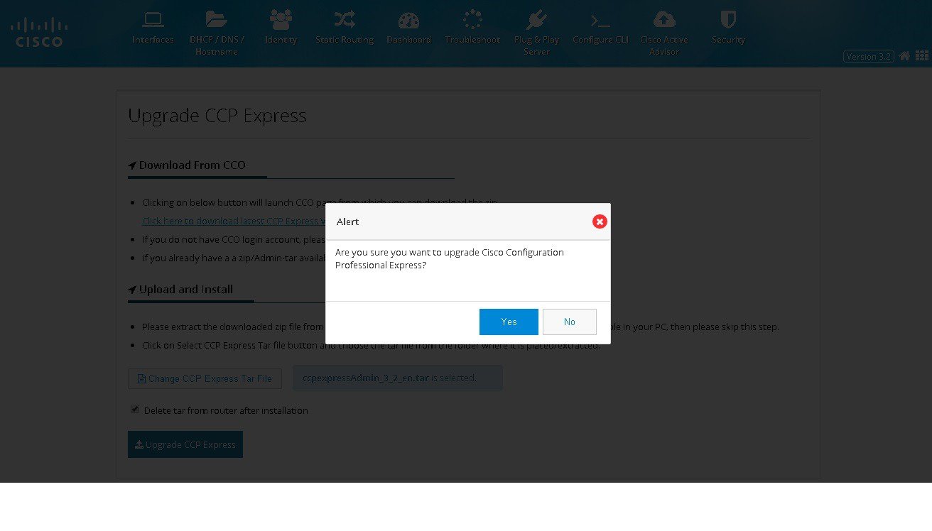
Step 7 Click YES to confirm Upgrade CCP express. It takes time to upgrade and below page will be displayed. (Figure 101)
Figure 101 Upgrade CCP Express
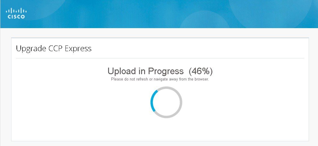
Step 8 If upgrade fails, click TRY AGAIN. (Figure 102)
Figure 102 Upgrade CCP Express
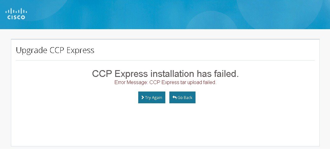
Step 9 After upgrading the CCP Express, it automatically takes you to the Landing Page with updated version. (Figure 103)
Figure 103 Upgrade CCP Express

Update Cisco IOS
To update the Cisco IOS on the device, perform these steps:
Step 1 Click on the USER Menu.
Step 2 Select the Update IOS option, The Update IOS page is displayed with list of IOS images present on the device.
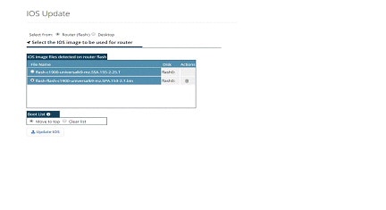
Step 3 To upload a relevant Cisco IOS image, click on the Desktop option.
Step 4 Click on the link to download the latest Cisco IOS version, if you do not have a CCO login, register it. Ensure to download the recommended and/or latest version for the device.
Step 5 If you have the relevant Cisco IOS image file on your PC, skip the above step.
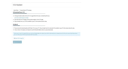
Step 6 Click on Select IOS image file and choose the Cisco IOS file from the folder, and click Upload IOS File.
Step 7 Proceed with the upload by clicking Yes. If the upload fails, click on the TRY AGAIN option and proceed with it again.
Step 8 After the upload is completed, the application automatically comes back to the IOS Update main page (Figure 32) and lists all the available Cisco IOS images on the router.
Step 9 Choose the Cisco IOS image that you want to add to the boot list. You may choose to have only one image in the boot list or move the image to the top of the boot list.
Step 10 After Upgrading the CCP Express, it automatically takes you to the Landing Page with Updated version.
Download Running Configuration
CCP Express allows user to download the running configuration of the device as a text file to your laptop or desktop in one click. To download the running configuration, perform these steps:
Step 1 Click on Download icon Menu on the page header.
Figure 106 Downloading Running Configuration
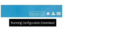
Step 2 The file will be downloaded with the following name format: RunningConfigBackup_<Date_Time>_<HostName/IPAddress>.txt
Timezone and NTP Configuration
In the advanced options, Timezone and NTP configuration options are available. To configure timezone and NTP configuration, perform these steps:
Step 1 Click General Settings > Time, and set the time.
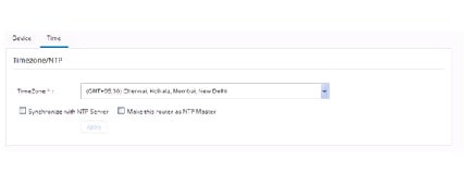
Step 2 User can select the standard Timezones listed in the drop-down list.
Step 3 You can choose to synchronize with any NTP servers. You can also choose to make the device as the NTP master.
Step 4 If you select the synchronization with NTP Server option, then based on the Timezones selection, value will populate for the NTP Server. User is allowed to manually enter any known NTP server hostnames or IP addresses.
ACL
ACL is an integrated feature that is used to filter the network traffic passing through the IOS devices. CCP Express allows to configure the IPv4 ACL which has Standard and Extended types that supports both named and numbered ACL.
ACL Summary
To view the ACL summary, perform these steps:
Step 1 Click ACL to display the summary screen of the ACL. The summary screen lists all existing ACL and option to add, edit, clone, and delete an existing ACL
Figure 108 The ACL Summary Table
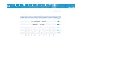
Add a Standard ACL
To add a standard ACL, perform these steps:
Step 1 Click ACL > click Add. The Add ACL dialog box appears.
Step 2 From the Add ACL dialog box, select the standard option and provide ACL Name/Number (0-99 for standard), Rule to permit/deny, IP address with two options either ‘any’ or ‘valid IP address and wildcard Mask’.
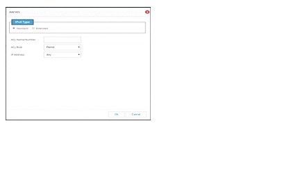
Add an Extended ACL
To Add an Extended ACL, perform these steps:
Step 1 Click ACL > Add. The ACL dialog box appears.
Step 2 From the ACL dialog box, select Extended Option and provide the ACL Name/Number(100-199 for extended), Rule, and the source and destination Address with valid id and wildcard mask.
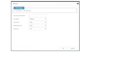
Step 3 Select a protocol. If TCP/UDP is selected, then select the source port and destination port from the given list.
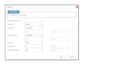
Step 4 If an ACL needs to be cloned, then select an ACL and click on the clone button.
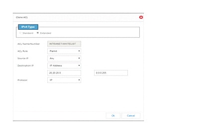
Binding Interface, VTY and HTTP
To bind an ACL, perform these steps:
Step 1 Click ACL > One ACL > ACL mapping icon. ACL Binding dialog box appears.
Step 2 Select the required Interface and add its route. Select the require VTY route and add the VTY value.
Step 3 HTTP will be enabled only for standard numbered ACL.
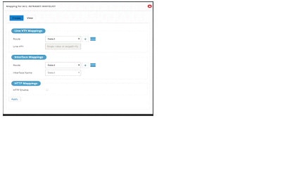
Step 4 Click the View tab to see all the mapped values under one ACL.
Figure 114 Viewing Existing Mapping
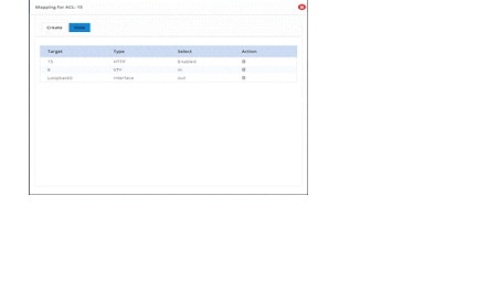
Note To select a specific user group, the user group should have been added through the Identity feature.
Cisco and the Cisco logo are trademarks or registered trademarks of Cisco and/or its affiliates in the U.S. and other countries. To view a list of Cisco trademarks, go to this URL: www.cisco.com/go/trademarks . Third-party trademarks mentioned are the property of their respective owners. The use of the word partner does not imply a partnership relationship between Cisco and any other company. (1721R)
Any Internet Protocol (IP) addresses and phone numbers used in this document are not intended to be actual addresses and phone numbers. Any examples, command display output, network topology diagrams, and other figures included in the document are shown for illustrative purposes only. Any use of actual IP addresses or phone numbers in illustrative content is unintentional and coincidental.
 Feedback
Contact Cisco
- Open a Support Case

- (Requires a Cisco Service Contract)