Install the Cisco PON Pluggable OLT
For steps to install the Cisco PON pluggable OLT refer to Install and Remove Transceiver Modules in the Cisco NCS 540 Router Hardware Installation Guide.
The documentation set for this product strives to use bias-free language. For the purposes of this documentation set, bias-free is defined as language that does not imply discrimination based on age, disability, gender, racial identity, ethnic identity, sexual orientation, socioeconomic status, and intersectionality. Exceptions may be present in the documentation due to language that is hardcoded in the user interfaces of the product software, language used based on RFP documentation, or language that is used by a referenced third-party product. Learn more about how Cisco is using Inclusive Language.
Completing the implementation of the Cisco Routed PON Solution requires setting up the various components that make up the system. At a high level, the steps to configure the Cisco Routed PON Solution are as follows:
Install the Cisco PON pluggable OLT.
Install and configure the Cisco PON Manager.
Install and configure the MongoDB database.
Install and configure the the Netconf Server.
Configure and activate the Cisco PON Controller.
Ensure that you use the following PON controller, PON manager, OLT or ONU firmware, and Netconf versions for the Cisco IOS XR 26.x.x.
|
IOS XR Release |
PON Controller |
PON Manager |
OLT/ONU Firmware |
Netconf |
|---|---|---|---|---|
|
26.2.1 |
6.1.0 |
6.1.0 |
6.1.0 |
6.1.0 |
|
26.1.1 |
6.1.0 |
6.1.0 |
6.1.0 |
6.1.0 |
For steps to install the Cisco PON pluggable OLT refer to Install and Remove Transceiver Modules in the Cisco NCS 540 Router Hardware Installation Guide.
For steps to install the Cisco Routed XGS-PON ONT refer to the Hardware Installation Guide for Cisco Routed XGS-PON ONT.
For steps to install the PON Manager, refer to PON Manager Installation in the Cisco Routed PON Installation Guide.
For steps to install the MongoDB database, refer to MongoDB Installation in the Cisco Routed PON Installation Guide.
The PON Controller is installed on a Docker container on the router. The PON Controller installation package is stored either on the hard disk of the router or on a network server to which the router has access.
To configure the PON controller, follow the steps:
For the Cisco Routers using the Cisco IOS XR7 framework, execute the following commands to install the software package:
 Note |
This section is applicable for the following routers:
|
Execute the following command to confirm if the PON Controller package is present in the router:
show install active summary | i ponSample Output
RP/0/RP0/CPU0:PON-Rtr1-CrLk#show install active summary | i pon
Tue Feb 27 08:45:29.246 UTC
xr-pon-ctlr                                                   24.1.1.40Iv1.0.1-1
If the PON Controller isn’t present, the command won’t return any value.
If the PON Controller isn’t present refer to the appropriate guide for steps to download and configure additional packages. The steps to configure an additional package might differ based on the router model.
For NCS 5500 or NCS 5700 router, refer to Install Optional Packages to Provide Additional Functionality in System Setup and Software Installation Guide for Cisco NCS 5500 Series Routers.
For NCS 540 router, refer to Install Optional Packages to Provide Additional Functionality in System Setup and Software Installation Guide for Cisco NCS 540 Series Routers.
This section provides the steps to configure Cisco PON Controller software in the routers using the IOS XR framework.
Note |
This section is applicable for the below routers:
|
Execute the following command to confirm if the PON Controller package is present in the router:
show install active | i ponSample Output
RP/0/RP0/CPU0:PON-Rtr5-Peyto#show install active | i pon
Tue Feb 27 08:44:53.345 UTC
ncs5500-pon-ctlr-1.0.0.0-r241140I
ncs5500-pon-ctlr-1.0.0.0-r241140I
If the PON Controller isn’t present, the command doesn’t return any values.
If the PON Controller isn’t present refer to the appropriate guide for steps to download and configure additional packages. The steps to configure an additional package might differ based on the router model.
For NCS 5500 or NCS 5700 router, refer to Install Packages in System Setup and Software Installation Guide for Cisco NCS 5500 Series Routers.
For NCS 540 router, refer to Install Packages in System Setup and Software Installation Guide for Cisco NCS 540 Series Routers.
<rpc xmlns="urn:ietf:params:xml:ns:netconf:base:1.0" message-id="101">
  <edit-config>
    <target>
      <candidate/>
    </target>
    <config>
      <pon-ctlr xmlns="http://cisco.com/ns/yang/Cisco-IOS-XR-um-pon-ctlr-cfg">
        <cfg-file>harddisk:/PonCntlInit.json</cfg-file>
        <vrf>default</vrf>
        <tls-pem>tls_file</tls-pem>
      </pon-ctlr>
    </config>
  </edit-config>
</rpc>
Replace the PonCntlInit.json with the appropriate JSON configuration file name.
Change default in the <vrf> element if you want to specify a different VRF instance.
Update tls_file in the <tls-pem> element to the name of the correct TLS PEM file.
For steps to configure the NETCONF server, refer to Routed PON Netconf Server Installation in the Cisco Routed PON Installation Guide.
After installing up the PON Controller in the router, you need to activate it by connecting to MongoDB and applying additional configurations to the controller.
Before you begin:
Ensure that you have synchronized the XR clock with that of an NTP server.
The steps to configure an NTP server might differ based on the router model. Refer to the appropriate guide for steps to configure an NTP server.
For NCS 5500 or NCS 5700 routers, refer to Configuring Network Time Protocol in System Management Configuration Guide for Cisco NCS 5500 Series Routers.
For NCS 540 router, refer to Synchronize Router Clock with NTP Server in System Setup and Software Installation Guide for Cisco NCS 540 Series Routers.
linux networking
 vrf default
  address-family ipv4
   default-route software-forwarding
   source-hint default-route interface MgmtEth0/RP0/CPU0/0
  !
 !
!
The steps to configure Linux Networking might differ based on the router model. Refer to the appropriate guide for steps to configure an NTP server.
For NCS 5500 or NCS 5700 routers, refer to Packet I/O on IOS XR in Application Hosting Configuration Guide for Cisco NCS 5500 Series Routers.
For NCS 540 router, refer to Setup the Linux Network for Application Hosting in Application Hosting Configuration Guide for Cisco NCS 540 Series Routers.
Ensure that the MongoDB server is reachable from your router by executing the following command:
bash ping <IP address of the MongoDB server>Sample Output
RP/0/RP0/CPU0:PON-Rtr5-Peyto#bash ping 192.0.2.0
Tue Feb 27 09:17:53.046 UTC
RP/0/RP0/CPU0:Feb 27 09:17:53.087 UTC: bash_cmd[66952]: %INFRA-INFRA_MSG-5-RUN_LOGIN : User lab logged into shell from con0/RP0/CPU0
PING 192.0.2.0 (192.0.2.0) 56(84) bytes of data.
64 bytes from 192.0.2.0: icmp_seq=1 ttl=64 time=0.820 ms
64 bytes from 192.0.2.0: icmp_seq=2 ttl=64 time=0.769 ms
64 bytes from 192.0.2.0: icmp_seq=3 ttl=64 time=0.703 ms
Edit the parameters in the PonCntlInit.json that is part of the PON Controller package establish connection with the MongoDB server. A sample PonCntlInit.json is included in the PON Controller package.
A sample PonCntlInit.json is given below:
{
    "CNTL": {
        "Auth": false,
        "CFG Version": "R4.0.0",
        "DHCPv4": false,
        "DHCPv6": false,
        "PPPoE": false,
        "UMT interface": "tibitvirt",
        "Maximum CPEs Allowed": 0,
        "Maximum CPE Time": 0
    },
    "DEBUG": {},
    "JSON": {
        "databaseDir": "/opt/cisco/poncntl/database/",
        "defaultDir": "/opt/cisco/poncntl/database/"
    },
    "Local Copy": {
        "CNTL-STATE": false,
        "OLT-STATE": false,
        "ONU-STATE": false
    },
    "Logging": {
        "Directory": "/var/log/tibit",
        "FileCount": 2,
        "FileSize": 5120000,
        "Tracebacks": false,
        "Timestamp": false,
        "Facility" : "user"
    },
    "MongoDB": {
        "auth_db": "cisco_users",
        "auth_enable": false,                                <-- field to enable CLI password authentication
        "ca_cert_path": "/etc/cisco/ca.pem",
        "compression": false,
        "write_concern": "default",
        "host": "192.0.2.0",                                <-- mongoDB server IP Address
        "name": "cisco_pon_controller",
        "password": "",
        "password_opts": {
                          "type": "keyring",
                          "keyring_path": "/etc/cisco/poncntl/keyring.data",
                          "keyring_key_path": "/etc/cisco/poncntl/keyring.key"
                        },
        "port": "27017",                                    <-- mongoDB port
        "tls_enable": false,                                <-- field to enable TLS based connection
        "username": "",
        "dns_srv": false,
        "db_uri": "",
        "replica_set_enable": false,
        "replica_set_name": "rs0",
        "replica_set_hosts":
            [
            "192.0.2.3:27017",                              <-- mongoDB replica set 1
            "192.0.2.4:27999",                              <-- mongoDB replica set 2
            "mongo02.example.com:17999"
            ],
        "validate_cfg": true
    },
    "databaseType": "MongoDB",
    "interface": "veth_pon_glb",
    "interface_namespace": ""
}
Change the host IP address parameter to the IP address of your MongoDB server.
(Optional) To enable secure connection between the PON Controller and the MongoDB server, change the value for tls_enable to true.
If a secure connection is enabled, you’ll need to configure the username and password parameters as well.
If you have configured a replica set for MongoDB, change the IP address for the MongoDB replica set.
Copy and paste the PonCntlinit.json file to either the hard disk of the router or to your network folder.
When copying the file to the hard disk of the router, it is stored in /misc/disk1 by default.
Confugure Controller using CLI or NETCONF RPC:
CLI
Execute the cfg-file command to initiate the PON controller, the command is used to load the PON controller application on the router.
Syntax
cfg-file <tftp transfer protocol>/package_path/ or harddisk/package_path/ vrf <vrf-name> tls-pem <tftp transfer protocol>/pem_file_path/ db-password <password>|
Parameter |
Decription |
||
|---|---|---|---|
|
tftp transfer protocol |
TFTP server IP address. |
||
|
package_path |
Location of the .json file.
|
||
|
Harddisk |
Harddisk of the router. If the .json file is located on the harddisk, provide the path to on the harddisk. |
||
|
vrf |
Specifies VPN routing and forwarding (VRF). |
||
|
vrf-name |
Name of a VRF used for MongoDB connectivity. |
||
|
tls-pem |
Specifies that TLS is used. |
||
|
pem_file_path |
Path of the .pem file. This can either be stored on the router harddisk or a TFTP server. |
||
|
db-password |
Password for the MongoDB server.
|
Example:
RP/0/RP0/CPU0:ios(config)#pon-ctlr cfg-file tftp://192.0.2.0/auto/tftp-users2/user2/PonCntlInit.json vrf default tls-pem tftp://192.0.2.0/auto/tftp-blr-users2/user/rootCA.pem db-password cisco@123$NETCONF RPC
<rpc xmlns="urn:ietf:params:xml:ns:netconf:base:1.0" message-id="101">
  <edit-config>
    <target>
      <candidate/>
    </target>
    <config>
      <pon-ctlr xmlns="http://cisco.com/ns/yang/Cisco-IOS-XR-um-pon-ctlr-cfg">
        <cfg-file>harddisk:/PonCntlInit2411MTBDHCPTest2.json</cfg-file>
        <vrf>default</vrf>
        <tls-pem>tls_file</tls-pem>
      </pon-ctlr>
    </config>
  </edit-config>
</rpc>
Note |
In the above configuration the PonCntlInit2411MTBDHCPTest2.json file is a sample file used to configure the Controller. |
For NCS 5500 or NCS 5700 routers, refer to Programmability Configuration Guide for Cisco NCS 5500 Series Routers.
For NCS 540 router, refer to Programmability Configuration Guide for Cisco NCS 540 Series Routers..
Ensure that the main interface for the SFP is in active.
RP/0/RP0/CPU0:ios(config)#interface TenGigE0/0/0/5
RP/0/RP0/CPU0:ios(config-if)#no shutdown
Create a subinterface with ID 4090 on the port where the small form-factor pluggable is inserted. The subinterface is required to receive the control packets between the PON Controller and the Cisco PON pluggable OLT.
interface TenGigE0/0/0/5.4090
encapsulation dot1q 4090
When the subinterface is created, the PON controller discovers the OLTs and ONUs in the network.
RP/0/RP0/CPU0:ios#run
Thu Oct 19 08:04:53.799 UTC
[xr-vm_node0_RP0_CPU0:~]$docker ps
CONTAINER ID IMAGE COMMAND CREATED STATUS PORTS NAMES
7909570b4803 cisco-poncntl.xr:R4.0.0 "/usr/bin/supervisor…" 26 hours ago Up 26 hours pon_ctlr
[xr-vm_node0_RP0_CPU0:~]$docker logs pon_ctlr --tail 50
2023-10-19 08:07:33.482 INFO PonCntl Total Controllers: 1 OLTs: 1 ONUs: 1
RP/0/RP0/CPU0:ios(config-if)#no shutdown
Run the lldp command to enable Link Layer Discovery Protocol (LLDP) for the OLT port. This helps in the discovery of the OLTs and ONUs in the PON Manager.
RP/0/RP0/CPU0:ios(config)# lldpConfirm if the PON Controller, OLT, and ONU details are displayed in the PON Manager.
Note |
If the Controller summary displays Status: as offline, then match the UTC clock on your router to that of the Cisco UCS server. |
For more information on PON Controller, refer to PON Controller in the Cisco Routed PON Installation Guide.
Type-B PON protection with multihoming is a network redundancy mechanism for Passive Optical Network (PON) deployments that
enables a standby PON Optical Line Terminal (OLT) to become active when the original active OLT fails or a fiber cut occurs
facilitates PON controller level protection by enabling the secondary PON controller to take over when the primary PON controller fails without switching OLT roles, and
assists router-level protection, so the PON controller and OLT on the secondary router take over when the router with the active PON controller fails.
|
Feature Name |
Release Information |
Feature Description |
|---|---|---|
|
Type-B PON protection with multihoming |
Release 26.2.1 |
You can now ensure uninterrupted subscriber service by continuously managing PON control and data traffic during equipment or link failures. Type-B PON protection with multihoming achieves this by enabling automatic switchover between active and standby Optical Line Terminals (OLTs). The automatic switchover establishes robust controller-level and router-level protection in XGS-PON deployments. This feature is supported on:
|
The convergence speed is designed to ensure reliable failover, typically occurring within seconds. While it may not achieve the sub-second failover speeds required for some high-availability applications, it provides a dependable transition that supports consistent network performance.
|
Attributes |
OLT-level protection |
PON controller-level protection |
Router-level protection |
|---|---|---|---|
|
Failover action |
Standby OLT assumes active role and handles traffic |
Secondary PON controller manages OLTs without switching OLT roles |
Secondary router's PON controller and OLTs become active |
Type-B protection with single-homing provides redundancy for different OLTs on the same router and its fiber path. It enables a standby OLT to become active if the active OLT or fiber connection fails. This mechanism ensures service continuity by switching traffic paths at the local OLT level. It is specifically designed to protect the immediate connection between the OLT and the ONUs.
Ensure that you implement these best practices when designing, configuring, and managing Type-B PON protection to maximize network resilience and minimize risk.
Avoid configuring OLTs in Cascading groups when protection is required, as these are not supported for Type-B PON protection.
Monitor the redundancy and operational status of both OLTs and all controller links regularly; promptly investigate and address any alarms or status changes.
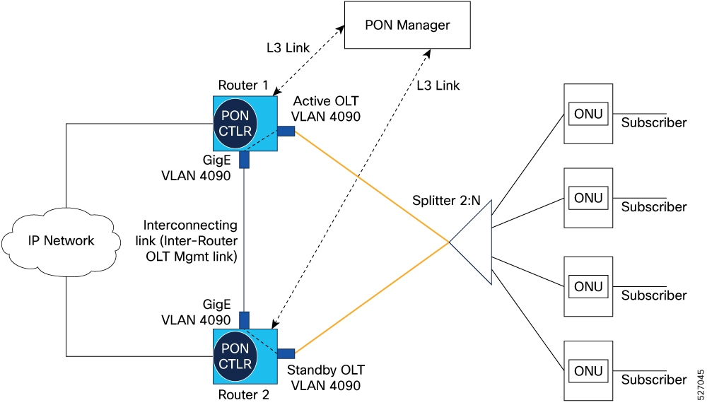
The key components involved in the process are:
Router: Each router hosts a PON controller instance.
PON Controller: The PON controller on each router identifies its local OLTs and discovers the OLTs on the peer router through the inter-router OLT management link. It manages both active and standby OLTs.
PON Manager: Configures the primary and secondary PON controllers, as well as the active and standby OLTs.
Inter-router OLT management link: A dedicated communication link between two routers that facilitates the PON controller to communicate with OLTs in the other peer routers.
This process ensures network connectivity and service continuity for subscribers by transitioning PON control from an active OLT to a standby OLT when a failure is detected .
These stages describe how Type-B PON protection provides redundancy in XGS-PON deployments:
Type-B PON protection enables rapid redirection of management traffic to a backup PON controller and subscriber traffic to a backup OLT in the event of failure, ensuring continuous network service and minimizing downtime for all subscribers.
Enable chassis-level redundancy and uninterrupted PON subscriber service by configuring Type-B PON protection with multi-homing.
Configure Type-B PON protection with multihoming when continuous service for PON subscribers is critical, such as during hardware or link failures.
Ensure these prerequisites are met:
PON Manager software installed to manage controllers and OLTs.
Cisco routers with PON feature support and the XR PON software image installed.
PON controller instances available and configured on both routers.
Ethernet link between routers (typically a dedicated VLAN; e.g., VLAN 4090 as a Layer 2 subinterface).
At least two OLTs, each connected to a separate router.
All ONUs inventoried on the OLTs, with both OLTs managed as primary by the same PON Controller.
Follow these steps to configure Type-B PON protection for redundancy.
|
Step 1 |
Enter PON controller configuration mode on each router. Example:If the controller instance does not exist, install or activate a valid instance before proceeding. Ensure XR PON software version compatibility. Repeat for each router. PON controller configuration mode is active on both routers. |
|
Step 2 |
Specify the configuration file path for each PON controller. Example:The controller uses the specified configuration file for setup. |
|
Step 3 |
Configure inter-router OLT management links to enable bidirectional OLT/controller communication. Example: |
|
Step 4 |
Configure the subinterface under the OLT port and the inter-router OLT management link port with encapsulation 4090. |
|
Step 5 |
Enable control-path communication between the OLT and the inter-router OLT management link. |
|
Step 6 |
Run the show l2vpn bridge-domain command to verify that the AC interfaces that carry the PON traffic into the router are up. |
|
Step 7 |
Run the show interface <inteface-name> command to verify that the subinterface state is up and is exchanging control traffic. |
The inter-router OLT management link for PON controller communication is enabled.
Add the OLTs to the inventory on both PON Controllers.
Assign both OLTs as primary in the first PON Controller.
Assign both OLTs as secondary in the second PON Controller.
Configuring an OLT protection partner
Enabling automatic switchover for OLT active and standby
Enabling automatic switchover with OLT toggle
Forcing a switchover from active OLT to standby OLT
 Feedback