Interfaces and Port Description
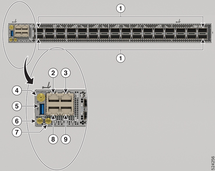
Cisco 8711-32FH-M
|
1 |
32 QSFP56-DD 400GbE ports or 16 QSFP-DD 800G ports. These ports support the following breakout operation:
|
6 |
Mini coax connector for 1 PPS, input, and output. |
||
|
2 |
Console port |
7 |
Mini coax connector for 10MHz, input, and output |
||
|
3 |
Time of the Day (ToD) port |
8 |
10G Control Plane Expansion port |
||
|
4 |
GNSS port
|
9 |
1G Management port |
||
|
5 |
USB Port Type-A |
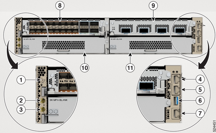
Cisco 8712-MOD-M
|
1 |
GNSS port
|
7 |
1G Management port |
||
|
2 |
Mini coax connector for 10MHz, input, and output |
8 |
MPA Slot 0 |
||
|
3 |
Mini coax connector for 1 PPS, input, and output. |
9 |
MPA Slot 1 |
||
|
4 |
Time of the Day (ToD) port |
10 |
MPA Slot 2 |
||
|
5 |
Console port |
11 |
MPA Slot 3 |
||
|
6 |
USB Port Type-A |
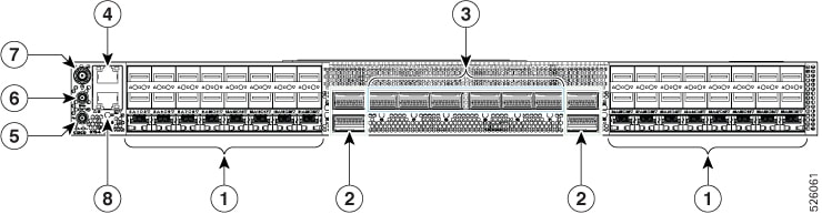
Cisco 8711-48Z-M
|
1 |
48 SFP56 ports
|
5 |
Mini coax connector for 1 PPS, input, and output. |
||
|
2 |
Four QSFP56 200GbE ports |
6 |
Mini coax connector for 10MHz, input, and output |
||
|
3 |
Six QSFP56-DD 400GbE ports |
7 |
GNSS port |
||
|
4 |
Management port |
8 |
Console |
 Note |
RJ-45 connector for Time-of-Day (TOD) interface, input, and output - TOD is available on the rear-side of the chassis. |
Transceiver and Cable Specifications
To determine which transceivers and cables are supported by this router, refer to the Transceiver Module Group (TMG) Compatibility Matrix Tool:
https://tmgmatrix.cisco.com/home


 Feedback