
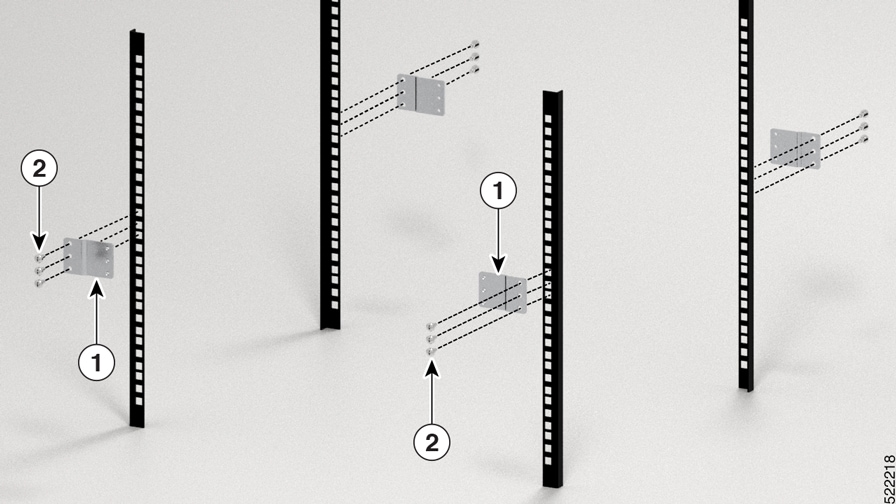
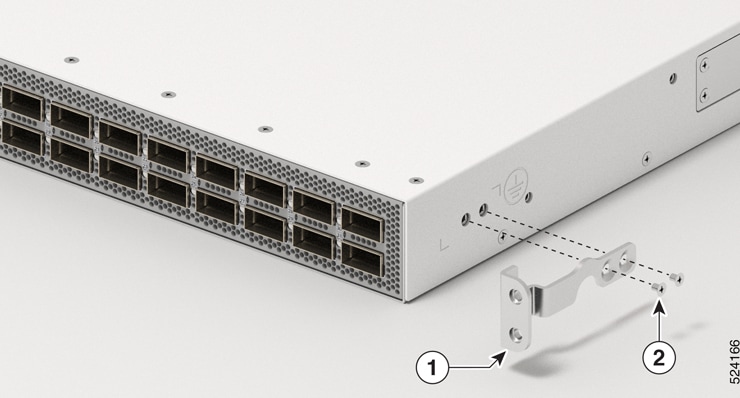
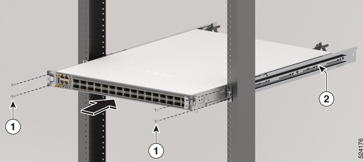
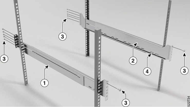
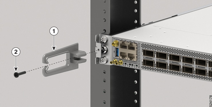
Install the Bracket Mounting Adapter on 23-inch Rack Post
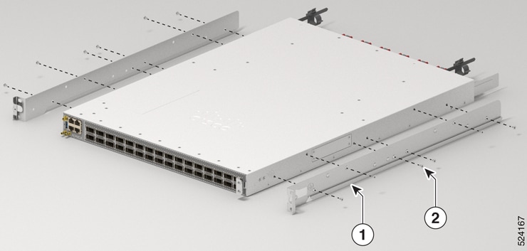
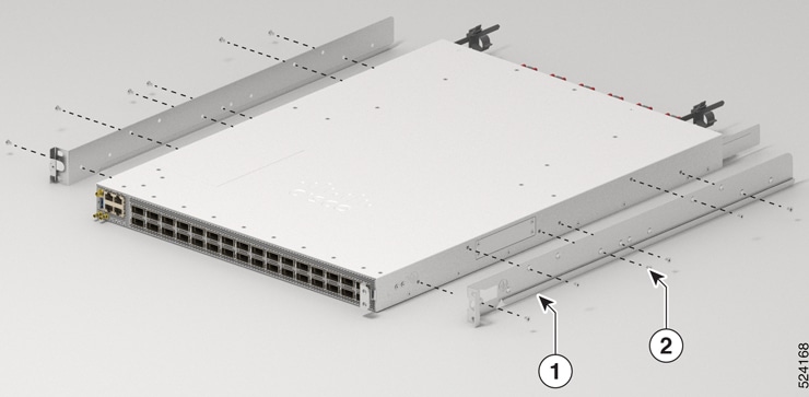
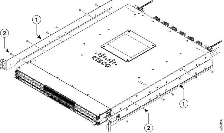
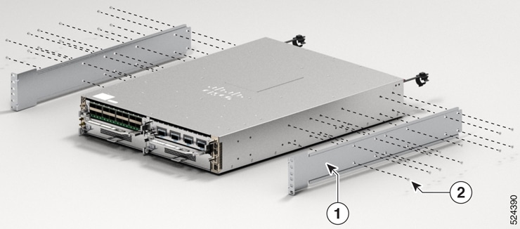
Rack Mount Kit
-
4 Post: NC57-2RU-ACC-KIT3
-
2 Post: NC57-2RU-ACC-KIT4
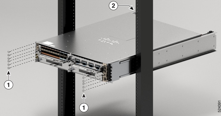
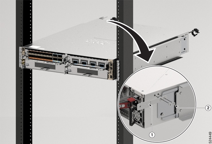
Procedure
|
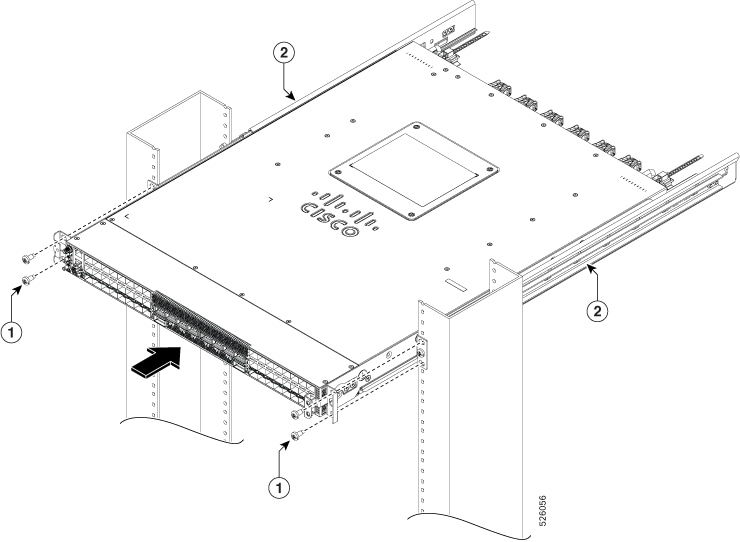
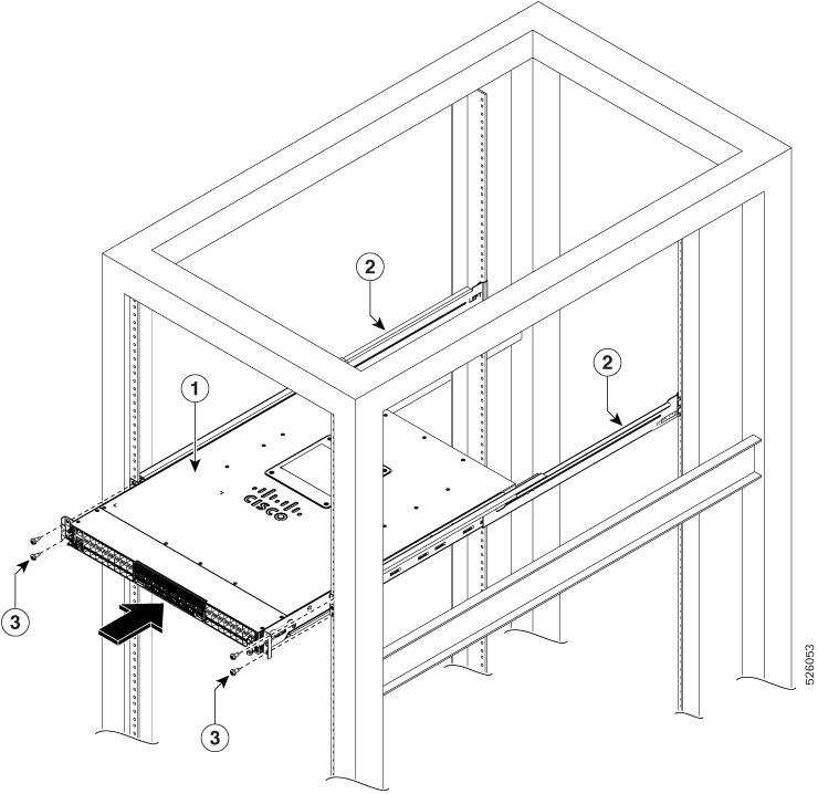
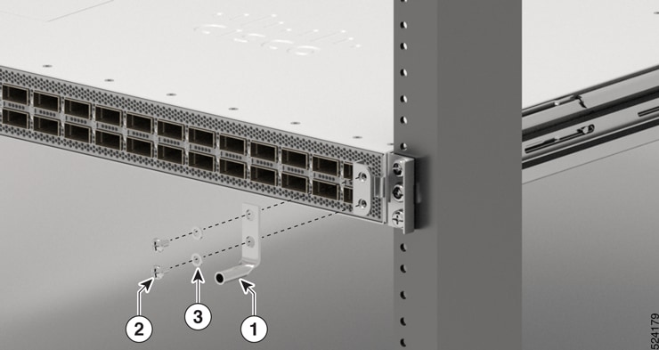
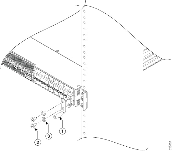
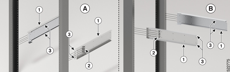
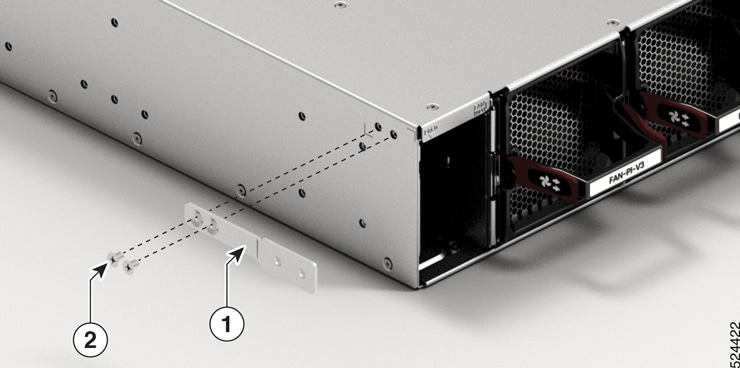
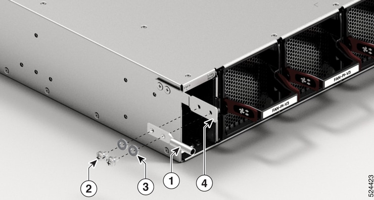
Mount the Bracket mounting adapter on the 23-inch rack post. Use three 12-24 Phillips pan-head screws with 30 in-lb (3.39 N.m) to attach each Bracket mounting adapter to the rear and front rack post on either sides. 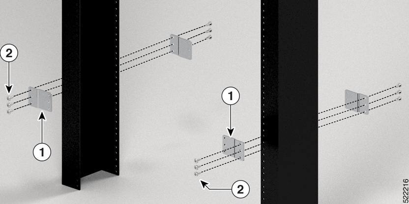
|
What to do next
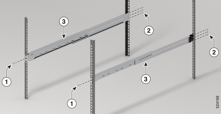
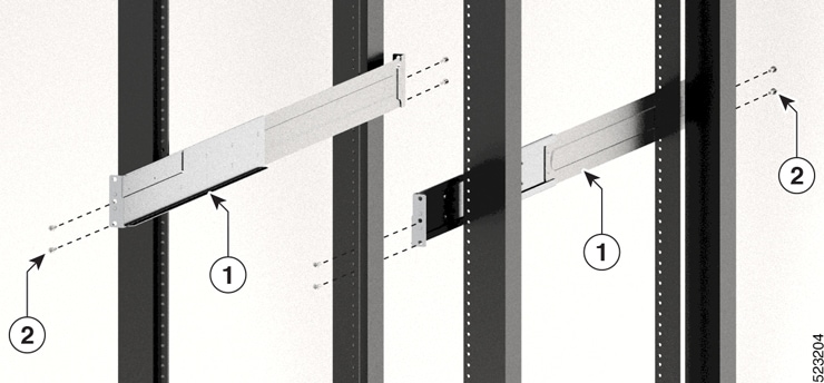
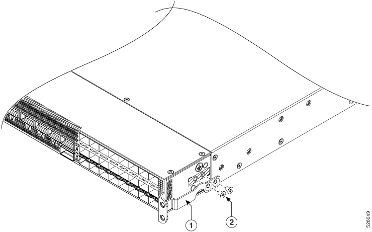
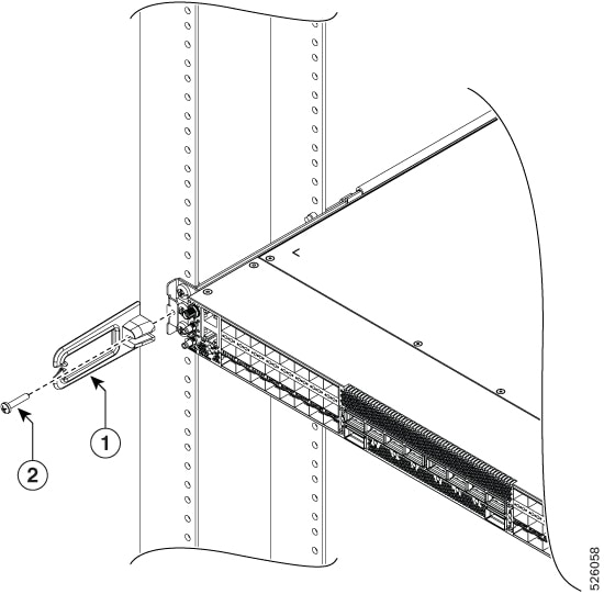
Continue with the installation of the router by referring to the procedures for the 19-inch rack post.


 Feedback