Prepare for Installation

This chapter provides preinstallation information, such as recommendations and requirements that must be met before installing your switch. Before you begin, inspect all items for shipping damage. If anything appears to be damaged or if you encounter problems installing or configuring your switch, contact customer service.


Note


The images in this chapter are only for representational purposes, unless specified otherwise. The chassis' actual appearance and size may vary.

Standard Warning Statements

This section describes the warning definition and then lists core safety warnings grouped by topic.

General Safety Warnings


Note


Statement 1089—Instructed and Skilled Person Definitions

An instructed person is someone who has been instructed and trained by a skilled person and takes the necessary precautions when working with equipment.

A skilled person or qualified personnel is someone who has training or experience in the equipment technology and understands potential hazards when working with equipment.


Warning


Statement 9001—Product Disposal

Ultimate disposal of this product should be handled according to all national laws and regulations.


Warning


Statement 1073—No User-Serviceable Parts

There are no serviceable parts inside. To avoid risk of electric shock, do not open.


Warning


Statement 1074—Comply with Local and National Electrical Codes

To reduce risk of electric shock or fire, installation of the equipment must comply with local and national electrical codes.


Note


Statement 407—Japanese Safety Instruction

You are strongly advised to read the safety instruction before using the product.

https://www.cisco.com/web/JP/techdoc/pldoc/pldoc.html

When installing the product, use the provided or designated connection cables/power cables/AC adapters.

〈製品使用における安全上注意〉

www.cisco.com/web/JP/techdoc/index.html

続ケーブル、電源コードセットACアダプタバッテリなどの部品、必添付品または

指定品をご使用ください。添付品指定品以外をご使用になると故障動作不良、火災

原因となりますまた、電源コードセットは弊社指定する製品以外機器には使用

できないためご注意ください。

Note


Statement 438—Taiwan RoHS

Restricted Substances Content Disclosure Table web address: http://www.cisco.com/go/taiwanrohs


Warning


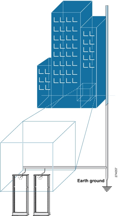
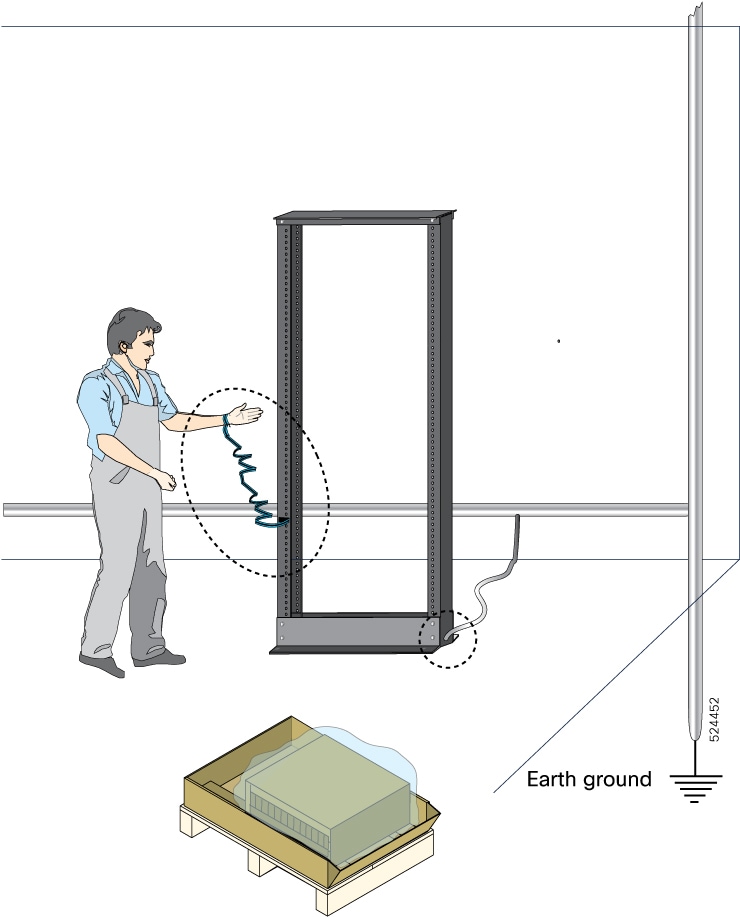
Statement 445—Connect the Chassis to Earth Ground

To reduce the risk of electric shock, connect the chassis of this equipment to permanent earth ground during normal use.


Warning


Statement 1020—Electrical Power Outlet with Grounding

In accordance with the ABNT NBR 5410 Electrical Installation Standard, this equipment must be connected to an electrical power outlet that has grounding (three pins), which protects the user against electric shocks.


Warning


Statement 1029—Blank Faceplates and Cover Panels

Blank faceplates and cover panels serve three important functions: they reduce the risk of electric shock and fire, they contain electromagnetic interference (EMI) that might disrupt other equipment, and they direct the flow of cooling air through the chassis. Do not operate the system unless all cards, faceplates, front covers, and rear covers are in place.


Warning


Statement 1057—Hazardous Radiation Exposure

Use of controls, adjustments, or performance of procedures other than those specified may result in hazardous radiation exposure.


Warning


Statement 1062—Remove Power Before Disconnecting

Explosion Hazard—Do not connect or disconnect any connector to this equipment unless power has been removed or you have verified that the area is nonhazardous. Secure any external connections that connect to this equipment by using screws, sliding latches, threaded connectors, or other means provided with this product.


Warning


Statement 1071—Warning Definition

IMPORTANT SAFETY INSTRUCTIONS

Before you work on any equipment, be aware of the hazards involved with electrical circuitry and be familiar with standard practices for preventing accidents. Read the installation instructions before using, installing, or connecting the system to the power source. Use the statement number at the beginning of each warning statement to locate its translation in the translated safety warnings for this device.

SAVE THESE INSTRUCTIONS


Note


Statement 1089—Instructed and Skilled Person Definitions

An instructed person is someone who has been instructed and trained by a skilled person and takes the necessary precautions when working with equipment.

A skilled person or qualified personnel is someone who has training or experience in the equipment technology and understands potential hazards when working with equipment.


Warning


Statement 1093—Avoid Sharp Edges

Risk of personal injury. Avoid sharp edges when installing or removing replaceable units.


Note


Statement 8006—CE Mark


Safety Guidelines

Before you perform any procedure in this document, review the safety guidelines in this section to avoid injuring yourself or damaging the equipment. The following guidelines are for your safety and to protect the equipment. Because the guidelines do not include all hazards, be constantly alert.

  • Keep the work area clear, smoke and dust-free during and after installation. Do not allow dirt or debris to enter into any laser-based components.

  • Do not wear loose clothing, jewelry, or other items that could get caught in the switch or other associated components.

  • Cisco equipment operates safely when used in accordance with its specifications and product-usage instructions.

  • If potentially hazardous conditions exist, do not work alone.

  • Take care when connecting multiple units to the supply circuit so that wiring is not overloaded.

  • This equipment must be grounded. Never defeat the ground conductor or operate the equipment in the absence of a suitably installed ground conductor. Contact the appropriate electrical inspection authority or an electrician if you are uncertain about whether suitable grounding is available.

  • When installing or replacing the unit, the ground connection must always be made first and disconnected last.

  • To prevent personal injury or damage to the chassis, never attempt to lift or tilt the chassis using the handles on modules (such as power supplies, fans, or cards); these types of handles are not designed to support the weight of the unit.

  • Hazardous voltage or energy is present on the backplane when the system is operating. Use caution when servicing.

Laser Safety


Warning


Statement 1051—Laser Radiation

Invisible laser radiation may be emitted from disconnected fibers or connectors. Do not stare into beams or view directly with optical instruments.


Warning


Statement 1055—Class 1/1M Laser

Invisible laser radiation is present. Do not expose to users of telescopic optics. This applies to Class 1/1M laser products.


Warning


Statement 1255—Laser Compliance Statement

Pluggable optical modules comply with IEC 60825-1 Ed. 3 and 21 CFR 1040.10 and 1040.11 with or without exception for conformance with IEC 60825-1 Ed. 3 as described in Laser Notice No. 56, dated May 8, 2019.


Energy Hazard

The switches can be configured for a DC power source. Do not touch terminals while they are live. Observe the following warning to prevent injury.

Preventing Electrostatic Discharge Damage

Many switch components can be damaged by static electricity. Not exercising the proper electrostatic discharge (ESD) precautions can result in intermittent or complete component failures. To minimize the potential for ESD damage, always use an ESD-preventive antistatic wrist strap (or ankle strap) and ensure that it makes adequate skin contact.


Note


Check the resistance value of the ESD-preventive strap periodically. The measurement should be 1–10 megohms.

Before you perform any of the procedures in this guide, attach an ESD-preventive strap to your wrist and connect the leash to the chassis.

Cautions and Regulatory Compliance Statements for NEBS

The NEBS-GR-1089-CORE regulatory compliance statements and requirements are discussed in this section.


Note


Statement 7001—ESD Mitigation

This equipment may be ESD sensitive. Always use an ESD ankle or wrist strap before handling equipment. Connect the equipment end of the ESD strap to an unfinished surface of the equipment chassis or to the ESD jack on the equipment if provided.


Warning


Statement 7003— Shielded Cable Requirements for Intrabuilding Lightning Surge

The intrabuilding port(s) of the equipment or subassembly, which is the management Ethernet port, must use shielded intrabuilding cabling/wiring that is grounded at both ends.


Warning


Statement 7005— Intrabuilding Lightning Surge and AC Power Fault

The intrabuilding port(s) of the equipment or subassembly, which is the management Ethernet port, must not be metallically connected to interfaces that connect to the OSP or its wiring. These interfaces are designed for use as intrabuilding interfaces only (Type 2 or Type 4 ports as described in GR-1089-CORE) and require isolation from the exposed OSP cabling. The addition of Primary Protectors is not sufficient protection in order to connect these interfaces metallically to OSP wiring.


Note


Statement 7011— Surge Protection Device Requirements for GR-1089 Antenna Ports

Protect equipment antenna ports, that are classified as Type 6 according to GR-1089-CORE, with lightning surge protectors that are rated at a minimum of 600 V peak surge of 1.2/50 uS duration.

Connecting a Cable to the GNSS Antenna Interface

  • GNSS modules have built-in ESD protections on all pins, including the RF-input pin. However, additional surge protection is required if an outdoor antenna is being connected. The Lightning Protector must be able to provide a low clamping voltage (less than 600V).

  • A lightning protection must be mounted at the place where the antenna cable enters the building. The primary lightning protection must be capable of conducting all potentially dangerous electrical energy to PE (Protective Earth).

  • Surge arrestors should support DC-pass and suitable for the GPS frequency range (1.575GHz) with low attenuation.


Warning


Statement 7012—Equipment Interfacing with AC Power Ports

Connect this equipment to AC mains that are provided with a surge protective device (SPD) at the service equipment that complies with NFPA 70, the National Electrical Code (NEC).


Note


Statement 7013—Equipment Grounding Systems—Common Bonding Network (CBN)

This equipment is suitable for installations using the CBN.


Warning


Statement 7016— Battery Return Conductor

The battery return conductor of this equipment shall be treated as Isolated DC return (DC-I).


Note


Statement 7018—System Recover Time

The equipment is designed to boot up in less than 30 minutes provided the neighboring devices are fully operational.


Note


Statement 8015—Installation Location Network Telecommunications Facilities

This equipment is suitable for installation in network telecommunications facilities.


Note


Statement 8016—Installation Location Where the National Electric Code (NEC) Applies

This equipment is suitable for installation in locations where the NEC applies.


Installation Guidelines

Before installing the chassis, ensure that the following guidelines are met:

  • Site is properly prepared so that there is sufficient room for installation and maintenance.

  • Operating environment is within the ranges that are listed in Environment and Physical specifications. For more details on environmental requirements, see Cisco 8700 Router Data Sheet.

  • Chassis is mounted at the bottom of the rack if it is the only unit in the rack.

  • When mounting the chassis in a partially filled rack, load the rack from the bottom to the top with the heaviest component at the bottom of the rack.

  • If the rack is provided with stabilizing devices, install the stabilizers before mounting or servicing the chassis in the rack.

  • Airflow around the chassis and through the vents is unrestricted.

  • Cabling is away from sources of electrical noise, such as radios, power lines, and fluorescent lighting fixtures. Make sure that the cabling is safely away from other devices that might damage the cables.

  • Each port must match the wave-length specifications on each end of the cable, and the cable must not exceed the stipulated cable length.


Note


Cisco 8000 Series Routers function in operating temperatures of up to 40°C at sea level. For every 300 meters (1000 ft) elevation upto 1800 meters (6000 ft), the maximum temperature is reduced by 1°C. For more details on environmental requirements, see Cisco 8700 Router Data Sheet.


Procure Tools and Equipment

Obtain these necessary tools and equipment for installing the chassis:

  • Number 1 and number 2 Phillips screwdrivers with torque capability to rack-mount the chassis.

  • 3/16-inch flat-blade screwdriver.

  • Tape measure and level.

  • ESD wrist strap or other grounding device.

  • Antistatic mat or antistatic foam.

  • Two-hole ground lug (1).

  • A crimping tool specified by the lug manufacturer that is large enough to accommodate the girth of the lug.

  • Wire-stripping tool.

  • Optical transceiver extraction tool.

Router Accessory Kits

Router Accessory Kit

The accessory kits for the Cisco 8700 series router includes the following:

Table 1. Router Accessory Kits - Cisco 8712-MOD-M
Kit Name Kit PID Description Quantity

Rack mount kit for 4-post rack

NC57-2RU-ACC-KIT - 19 inch

NC57-2RU-ACC-KIT3 - 23 inch

Slider assembly - left and right

2

Slider brackets - left and right

2

12-24 Phillips pan-head screws

22

M4 x 5.7-mm Phillips flat head screws

22

Bracket mounting adapter (available only 23-inch rack-mount kit)

4

Ground lug

1

Rack mount kit for 2-post rack

NC57-2RU-ACC-KIT2 - 19 inch

NC57-2RU-ACC-KIT4 - 23 inch

Slider assembly - left and right

2

Slider brackets - left and right

2

12-24 Phillips pan-head screws

20

M4 x 5.7-mm Phillips flat head screws

26

Bracket mounting adapter (available only 23-inch rack-mount kit)

4

Ground lug

1

Table 2. Router Accessory Kits - Cisco 8711-32FH-M Router
Kit Name Kit PID Description Quantity

Rack mount kit for 4-post rack

8700-1RU-4P-KIT

Slider brackets

2

Slider assembly

2

Bracket mounting adapter

4

Cable management bracket

1

M5 x 12.45-mm Phillips dome-head screws

24

M5 x 7.93-mm Phillips dome-head screws

2

M4 x 5.7-mm Phillips flat-head screws

14

M4 x 20-mm Phillips dome-head screws

1

M5 washer

2

Ground lug

1

Ground lug extension bracket

1

Rack mount kit

for 2-post rack

8700-1RU-2P-KIT

Slider brackets

2

Slider assembly

2

Bracket mounting adapter

4

Cable management bracket

1

M5 x 12.45-mm Phillips dome-head screws

22

M5 x 7.93-mm Phillips dome-head screws

2

M4 x 5.7-mm Phillips flat-head screws

14

M4 x 20-mm Phillips dome-head screws

1

M5 washer

2

Ground lug

1

Ground lug extension bracket

1


Note


If you purchased this product through a Cisco reseller, you might receive more contents in your kit, such as documentation, hardware, and power cables.

The shipped cables depend on your specification when placing an order. See the Power Supply Power Cord Specifications section for information on the available power cords.


Discrepancies or Damage?

If you notice any discrepancies or damage, send the following information to your customer service representative by email:

  • Invoice number of the shipper (see the packing slip)

  • Model and serial number of the missing or damaged unit

  • Description of the problem and how it affects the installation

  • Photos of the damage to external packaging, internal packaging, and product

Prepare Your Location

This section illustrates how the building that houses the chassis must be properly grounded to the earth ground.


Note


Unless specified otherwise, the image is only for representational purposes. The rack's actual appearance and size may vary.

Note


This image is only for representational purposes. Your grounding requirement depends on your building.
Figure 1. Building with Rack Room Connected to Earth Ground

Airflow for Site Planning

Table 3. Cisco 8700 Airflow

Device

Maximum System Airflow (CFM) at Maximum System Temperature

Cisco 8712-MOD-M

370

Cisco 8711-32FH-M

160

Prepare Yourself

This section illustrates how to prepare yourself before removing the chassis from the sealed antistatic bag. The figures show how to cuff the ESD strap around the wrist and the ground cord that connects the cuff to the ground. ESD wrist straps are the primary means of controlling static charge on personnel.

Figure 2. Wearing the ESD Strap

Prepare Rack for Chassis Installation

Install the Cisco 8700 Series Routers on a standard 19 inch or 23 inch, Electronic Industries Alliance (EIA) rack with mounting rails that conform to English universal hole spacing according to Section 1 of the ANSI/EIA-310-D-1992 standard.


Note


The Cisco 8700 router rack mount kit contains the slider brackets for 19-inch rack. To install the chassis in a 23-inch rack or an ETSI rack, you need the bracket mounting adapter to accommodate the 19-inch rack mount brackets.


The spacing between the posts of the rack must be (EIA-310-D-1992 19-inch rack compatible) wide enough to accommodate the width of the chassis.

Figure 3. Rack Specification EIA (19 inches and 23 inches)
Table 4. Rack specification EIA (19 inches and 23 inches)

Post Type

Rack Type

Rack Front Opening (X)

Rack Mounting Hole Centre-Centre (Y)

Mounting Flange Dimension (Z)

4 Post

19 inches (48.3 centimeters)

450.8mm (17.75”)

465mm (18.312”)

482.6mm (19”)

2 Post

4 Post

23 inches (58.4 centimeters)

552.45mm (21.75”)

566.7mm (22.312”)

584.2mm (23”)

2 Post

Before you move the chassis or mount the chassis into the rack, we recommend that you do the following:

Procedure


Step 1

Place the rack at the location where you plan to install the chassis.

Step 2

(Optional) Secure the rack to the floor.

To bolt the rack to the floor, a floor bolt kit (also called an anchor embedment kit) is required. For information on bolting the rack to the floor, consult a company that specializes in floor mounting kits (such as Hilti; see Hilti.com for details). Ensure that floor mounting bolts are accessible, especially if annual retorquing of bolts is required.

Note


Ensure that the rack in which the chassis is being installed is grounded to earth ground.


Clearance Requirements

To ensure adequate airflow, we recommended that you maintain a minimum of 6 in. (15.24 cm) front and rear clearance for air intake/exhaust at room temperature up to 55C, and maintain a minimum of 4.0 in. (10.16 cm) front and rear clearance for air intake/exhaust at room temperature up to 40C. Leave an additional 6.0 in. (15.24 cm)/4.0 in. (10.16 cm) rear clearance for removal and installation of power supplies and fan modules.

If the router is installed in a perforated door cabinet, maintain a minimum of 6 in. (15.24 cm) from the inside of the door. The front and rear doors of the cabinet must be perforated with a minimum open area of 70%.

This figure shows the clearances required for the installation of Cisco 8700 Series Routers.

Figure 4. Clearances Required Around the Chassis - Cisco 8711-32FH
Figure 5. Clearances Required Around the Chassis - Cisco 8712-MOD-M

1

Chassis

4

  • 6.0 in. (15.24 cm) front clearance for air intake/exhaust at room temperature up to 55C

  • 4.0 in. (10.16 cm) front clearance for air intake/exhaust at room temperature up to 40C

2

  • 6.0 in. (15.24 cm) front clearance for air intake/exhaust at room temperature up to 55C

  • 4.0 in. (10.16 cm) front clearance for air intake/exhaust at room temperature up to 40C

5

Rear service area for the fan and power modules replacement

3

Chassis depth