
Replace Modular Port Adapters
The following sections describe how to remove or install an MPA:
Remove a Modular Port Adapter
Before you begin:
Use one of the following procedures to perform graceful shutdown of the card:
-
unscrew the captive screws, pull the release latch, and open ejector lever to trigger auto-shutdown of the card, and then verify that the Status LED is in Off state (The LED status transitions from Green to Red and Off which takes up to 5 seconds).
-
use the shutdown location location command in admin EXEC mode to shutdown the card. Then use the show platform command to verify that the Status LED is in Off state.
To remove an MPA, perform the following steps:
-
Perform the graceful shutdown of the MPA. Run the shutdown location location command in admin EXEC mode, which gracefully shuts down MPA to prevent any of the file systems from being corrupted.
-
Verify that the MPA Status LED for the slot that you specified turns off. Also, you can verify that the card is in the powered off state by running the show platform command.
-
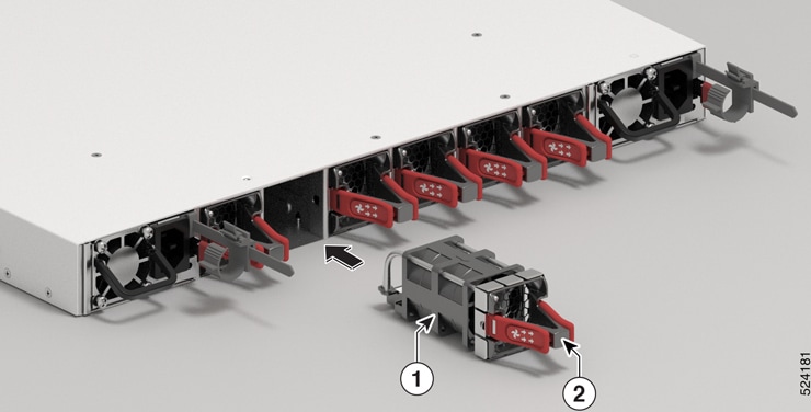
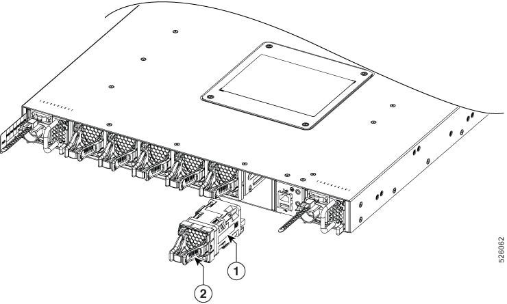
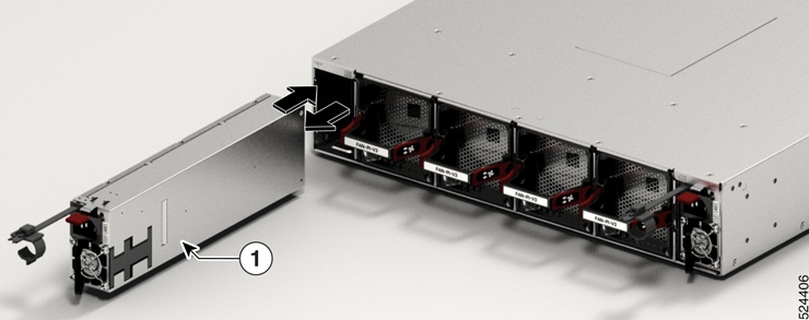
To remove the MPA from the chassis, loosen the captive screws (marked as 1 in the image) on the MPA.
-
Press the tab down (marked as 2 in the image).

Note
If you are removing the MPA without shutting it down gracefully, verify that the Status LED is in an Off state before proceeding to the next step.
-
Pull the ejector lever away from the MPA (marked as 3 in the image).
-
Grasp the MPA and pull the MPA from the chassis (marked as 4 in the image). (You have already disconnected the cables from the MPA.
1
Rotate the captive screw to loosen the MPA. 2
Press the tab down.
3
Pull the ejector lever away from the MPA.
Figure 1. Cisco 8712-MOD-M Router - Remove Modular Port Adapter 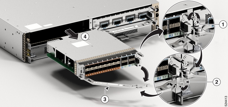
-
Proceed with installing an MPA.
Install a Modular Port Adapter
This section provides step-by-step instructions for installing a modular port adapter (MPA) in a Cisco 8700 Series router.
To install an MPA, perform the following steps:
-
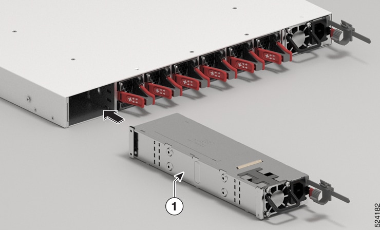
To insert the MPA, locate the guide rails inside the chassis that hold the MPA in place.
-
Carefully slide the MPA all the way in the chassis until the MPA is firmly seated in the MPA interface connector. When fully seated, the MPA might be slightly behind the faceplate.
Note
The MPA will slide easily into the slot if it is properly aligned on the tracks. If the MPA does not slide easily, do NOT force it. Remove the MPA and reposition it, paying close attention to engaging it on the tracks. Push the MPA inside the slot until you hear a click. Continue to push the MPA further until you hear a second click. The MPA is fully seated only after the second click is heard.
-
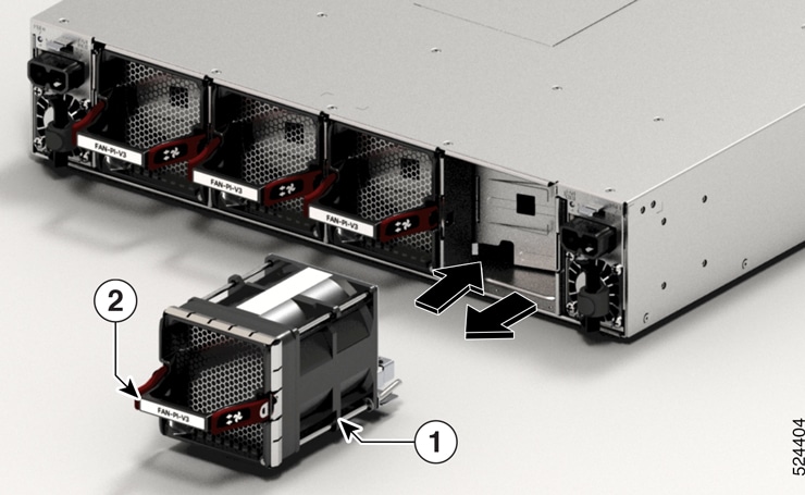
After the MPA is properly seated, push the ejector lever towards the chassis (marked as 2 in the image).
Note
If the ejector is not closed within 60 seconds and remains open for an extended period, the router will automatically shut down the MPA due to the open ejector status. When this occurs, the LED status will change from Amber to Off as the MPA shuts down. After the MPA has shut down, you can safely remove it from the slot, reinsert it, and lock the ejector. The MPA will then return to its standard workflow and become operational again. Once the MPA is operational, the LED status will change to Green.
-
Pull the tab up (marked as 3 in the image).
-
Use a number 2 Phillips screwdriver to tighten the captive screws (marked as 4 in the image) on the MPA.
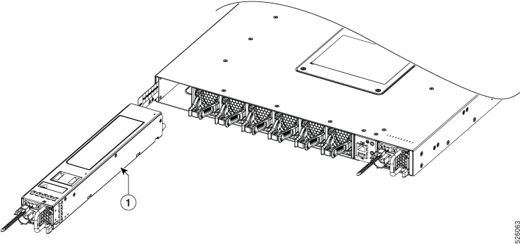
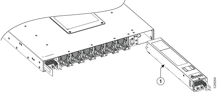
Figure 2. Cisco 8712-MOD-M Router - Install Modular Port Adapter 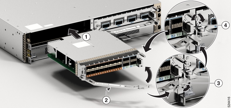
1
Slide the back end of the MPA into the open MPA slot. 2
Pull the ejector lever towards the MPA. 3
Pull the tab up.
4 Rotate the captive screw to tighten the MPA. Note
Do not over-torque the MPA captive screws when installing the MPA. Tighten the captive screws on the MPA to a torque of 9.7 in-lbs (1.09 N-m).
 Feedback