Replace Fan Modules
 Note |
Fan modules can be replaced only on the Cisco 8011-32Y8L2H2FH Router. |
 Caution |
If you cannot replace a fan module (FAN-1RU-PI-V3) within three minutes, we recommend that you leave it in the chassis until you are prepared to replace it within that specified time limit. |
Note |
If you remove more than one fan module at a time during operations, the router allows up to 2 minutes of operations before shutting down, unless you replace extra missing fan modules within that time. If the router senses an over temperature condition when multiple fan modules are removed, the shutdown can occur in less than 2 minutes. |
Procedure
|
Step 1 |
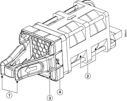
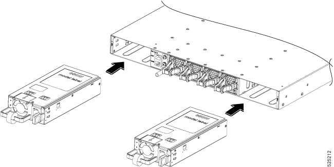
Press both the latches on the fan module to disengage the fan module connection from the chassis. |
||||||||
|
Step 2 |
Simultaneously press the latches, and pull the fan module fully out of the chassis. 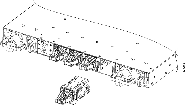
|

 Feedback