Rack Mounting the Router
You can choose to either set up the router on a rack or wall mount it.
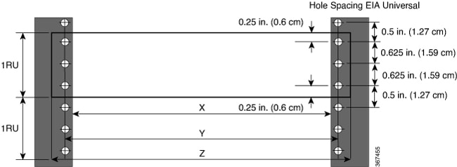
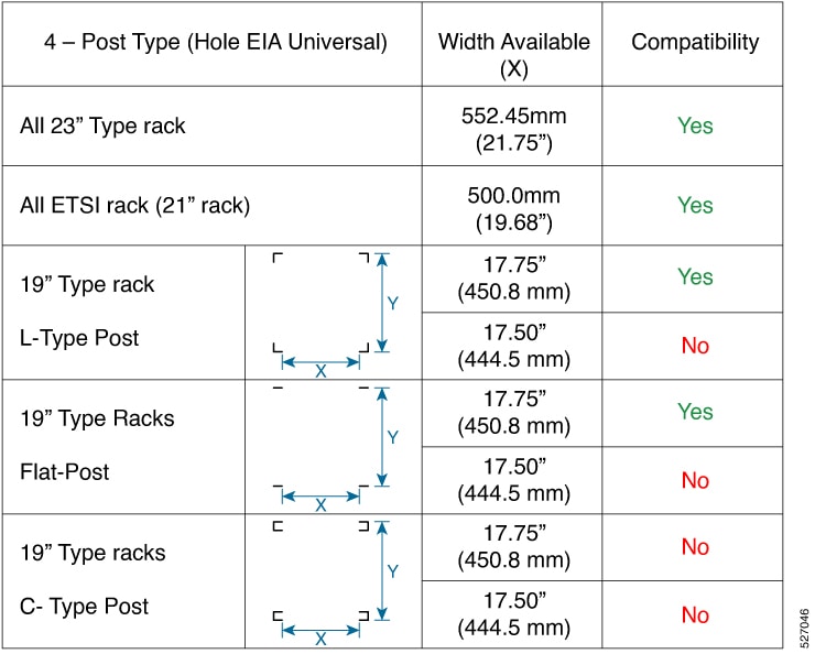
We recommend that you use the following racks while mounting the router.
|
Post Type |
Rack Type |
Rack Front Opening (X) |
Rack Mounting Hole Centre-Centre (Y) |
Mounting Flange Dimension (Z) |
|---|---|---|---|---|
|
4 Post |
19 inches (48.3 centimeters) |
17.75 inches (45 centimeters) |
18.31 inches (46.5 centimeters) |
19 inches (48.2 centimeters) |
|
2 Post |
||||
|
4 Post |
23 inches (58.4 centimeters) |
21.75 inches (55.24 centimeters) |
22.31 inches (56.6 centimeters) |
23 inches (58.4 centimeters) |
|
2 Post |
Rack Mounting Brackets
The router is shipped with rack mounting brackets that are to be secured on the sides of the router.
 Caution |
If the rack is on wheels, ensure that the brakes are engaged or the rack is otherwise stabilized. |
Cisco 8011-4G24Y4H-I Router
|
Product Identification Number |
Description |
|---|---|
|
RCKMT-19-V1 |
19 inch rack mounting kit |
|
RCKMT-23-V1 |
23 inch rack mounting kit |
|
RCKMT-ETSI-V1 |
ETSI rack mounting kit |
|
53-101699-01 |
Grounding lug kit |
|
CBL-BRKT-V1 |
Cable management |
|
53-101650-01 |
Wall mount bracket |
Cisco 8011-32Y8L2H2FH Router
|
Product identification number |
Description |
|---|---|
|
RCKMT-19-KIT1 |
19-inch 2-post rack mounting kit |
|
RCKMT-19-KIT2 |
19-inch 4-post rack mounting kit |
|
RCKMT-23-KIT1 |
23-inch 2-post rack mounting kit |
|
RCKMT-23-KIT2 |
23-inch 4-post rack mounting kit |
|
RCKMT-ETSI-KIT1 |
ETSI 2-post rack mounting kit |
|
RCKMT-ETSI-KIT2 |
ETSI 4-post rack mounting kit |
|
CBL-BRKT-V2 |
Cable management |
Cisco 8011-12G12X4Y Router
|
Product Identification Number |
Description |
|---|---|
|
RCKMT-19-A RCKMT-19-D |
19 inch rack mounting kit |
|
RCKMT-23-A RCKMT-23-D |
23 inch rack mounting kit |
|
RCKMT-ETSI-A RCKMT-ETSI-D |
ETSI rack mounting kit |
|
CBL-BRKT-V1 |
Cable management |
|
Quantity |
Part Description |
|---|---|
| 2 |
Rack-mount brackets |
| 8 (48-101850-01) |
M3 x 0.5 x 6-mm Phillips flat-head screws |
| 2 (48-101620-01) |
SCR, M, PAN, PH, SEX, 10-32 x 0.365"L, CSwZN, nickel alloy |
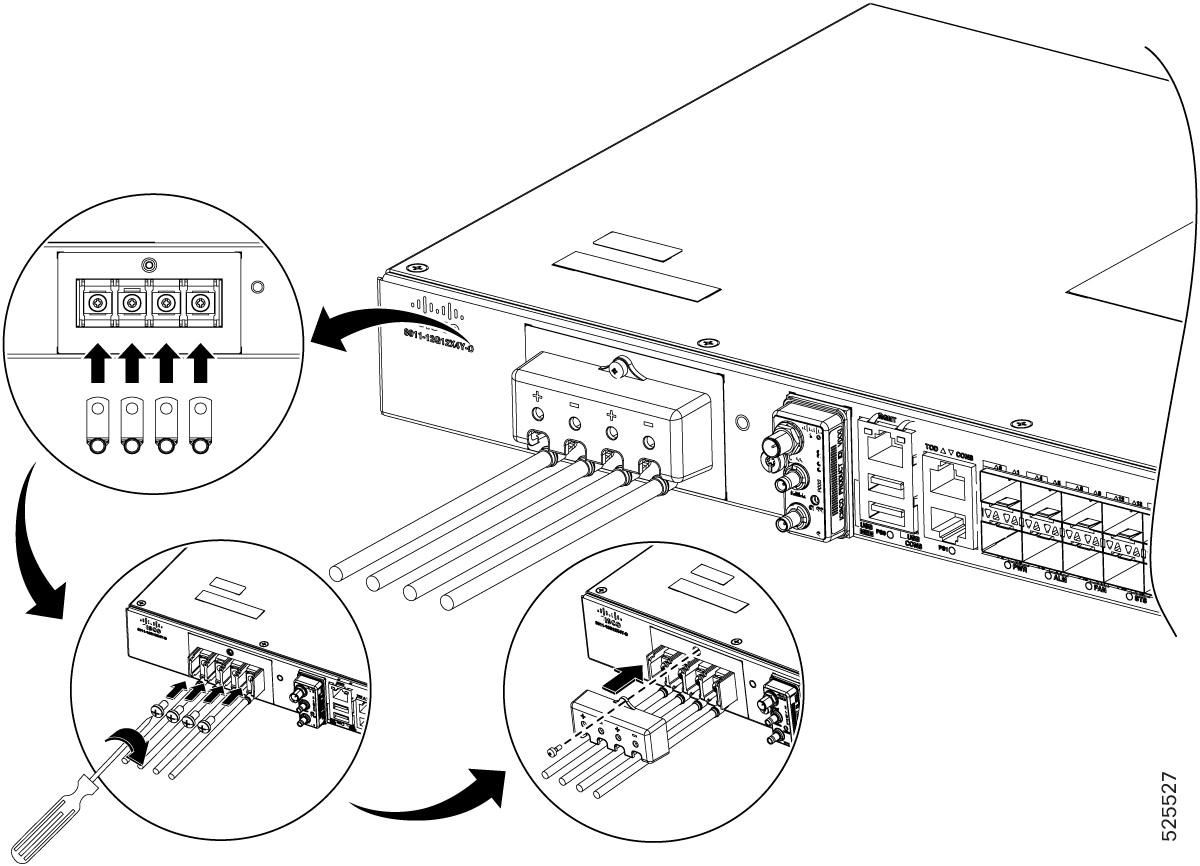
|
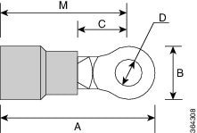
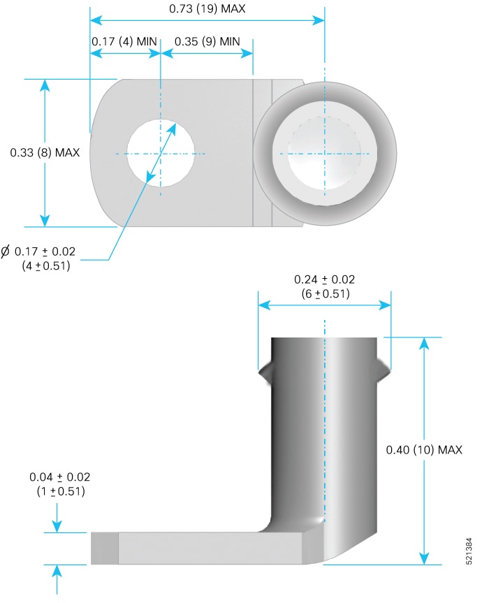
1 (32-0619-01) |
LUG, FAST, UNIN, #6AWG, #10, 2 HOLES |
|
4 (48-101690-01) |
SCR, M, PAN, PH, 12-24 x 0.49"L, CSwZN, nickel alloy |
Caution |
|
Mounting the Router on the Rack
Cisco 8011-4G24Y4H-I Router
To mount the router on the rack:
-
Attach the rack-mount brackets and the cable management to the router as follows:
-
The router has port-side intake modules, position the router so that its ports are facing the cold aisle.
-
Position the bracket ears facing front or middle rack-mount, on the side of the chassis so that the holes are aligned.
-
Use four M4 screws to attach the brackets to the chassis. Tighten the M4 screws to 13.3 inch-pounds (1.5 Nm).
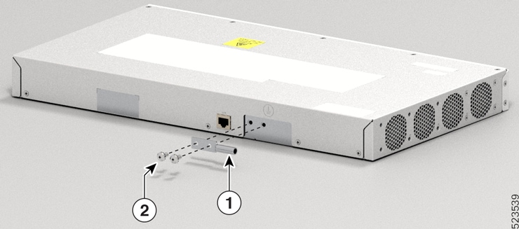
Figure 6. Installing 19 inch Rack-Mount Brackets in the Front 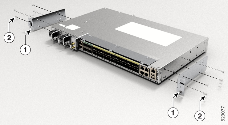
1
Mount Bracket
2
Screw
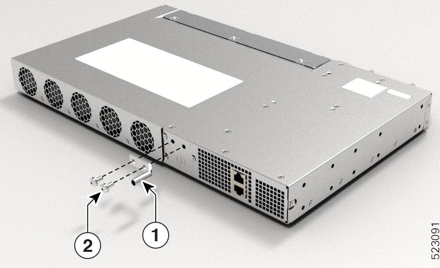
Figure 7. Installing Cable Management and 19 inch Rack-Mount Brackets in the Front 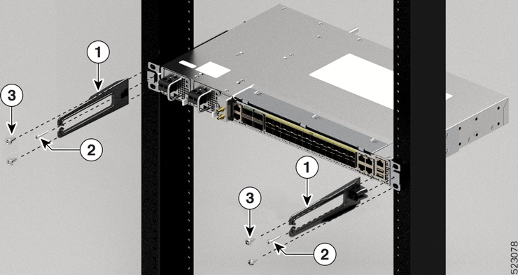
1
Cable Management Bracket
2
Cable Management Screw
3
Screw
Figure 8. Installing 19 inch Rack-Mount Brackets in the Middle 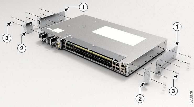
1
Mount Bracket
2
Cable Management Bracket
3
Screw
Figure 9. Installing Cable Management and 19 inch Rack-Mount Brackets in the Middle 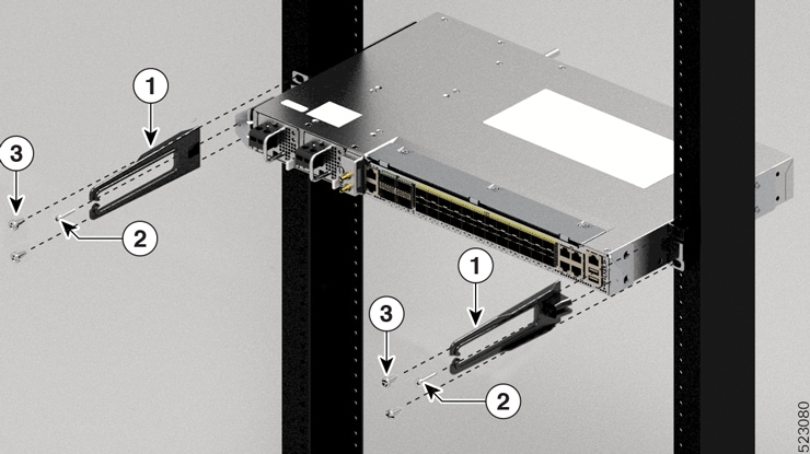
1
Cable Management Bracket
2
Cable Management Screw
3
Screw
Figure 10. Installing 23 inch Rack-Mount Brackets in the Front 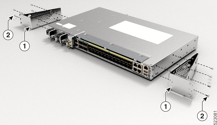
1
Mount Bracket
2
Screw
Figure 11. Installing Cable Management and 23 inch Rack-Mount Brackets in the Front 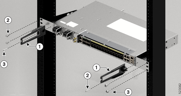
1
Cable Management Bracket
2
Cable Management Screw
3
Screw
Figure 12. Installing 23 inch Rack-Mount Brackets in the Middle 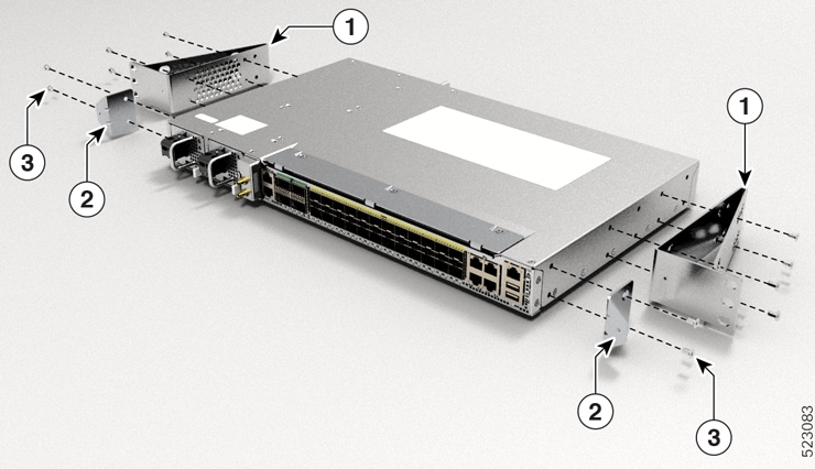
1, 2
Mount Bracket
3
Screw
Figure 13. Installing Cable Management and 23 inch Rack-Mount Brackets in the Middle 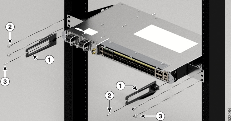
1
Cable Management Bracket
2
Cable Management Screw
3
Screw
Figure 14. Installing ETSI Rack-Mount Brackets in the Front 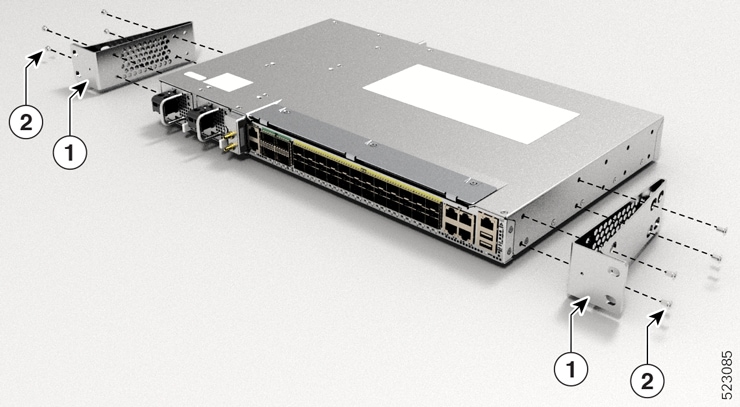
1
Mount Bracket
2
Screw
Figure 15. Installing Cable Management and ETSI Rack-Mount Brackets in the Front 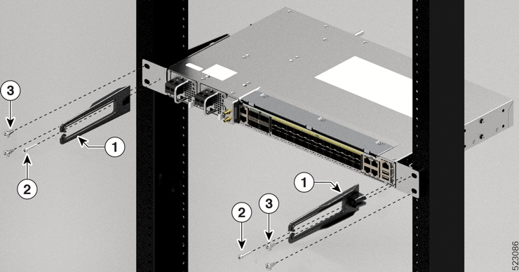
1
Cable Management Bracket
2
Cable Management Screw
3
Screw
Figure 16. Installing ETSI Rack-Mount Brackets in the Middle 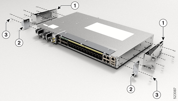
1,2
Mount Bracket
3
Screw
Figure 17. Installing Cable Management and ETSI Rack-Mount Brackets in the Middle 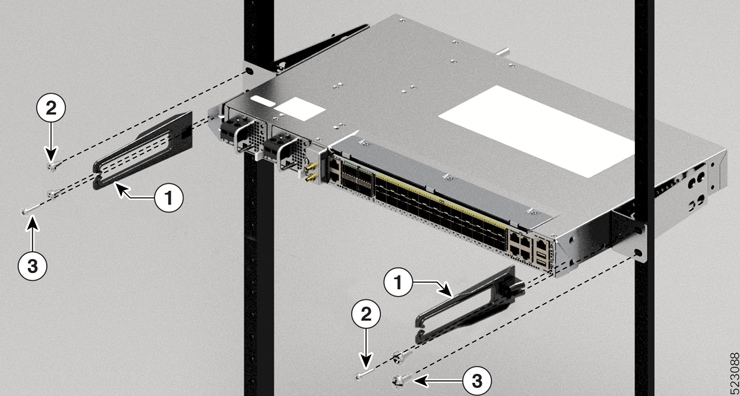
1
Cable Management Bracket
2
Cable Management Screw
3
Screw
-
Repeat Steps 1b and 1c with the other rack-mount bracket on the other side of the router.
-
Use four 12-24 screws and mount the router to the rack.
-
-
Install the router onto the 2-post rack as follows:
-
Lift and position the router into position between the two rack posts.
-
Move the router until the rack-mount brackets come in contact with the two rack posts.
-
Hold the chassis at level and have another while the second person inserts two screws 12-24 in each of the two rack-mount brackets (using a total of four screws) and into the cage nuts or threaded holes in the vertical rack-mounting rails.
-
Tighten the 12-24 screws to 30 in-lb (3.39 N.m).
-
Cisco 8011-32Y8L2H2FH – Two-post and four-post sliders
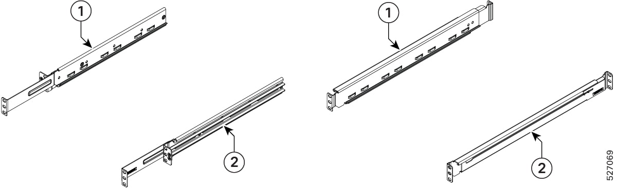
|
1 |
LH slider assembly (800-50378-01) |
|
2 |
RH slider assembly (800-50377-01) |
|
1 |
LH slider assembly (800-50376-01) |
|
2 |
RH slider assembly (800-50375-01) |
 Note |
Check the part number marking sticker on the slider to identify whether it is a LH or RH slider assembly. |
Cisco 8011-32Y8L2H2FH – Four-post LH and RH sliders
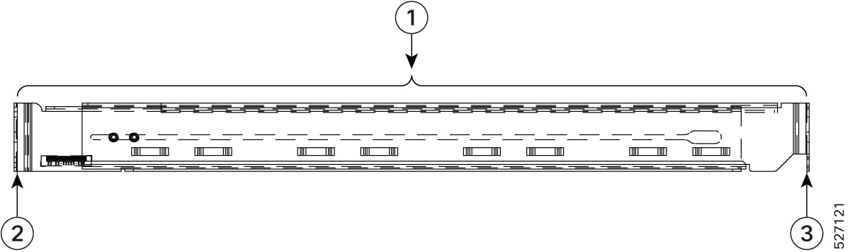
|
1 |
Mounting depth
|
|
2 |
Front rail mating surface |
|
3 |
Rear rail mating surface |
Note |
The front and rear vertical rails of four-post racks must be within the range, 500mm to 840mm to install the Cisco 8011-32Y8L2H2FH router. The Cisco 8011-32Y8L2H2FH router cannot be installed on a four-post rack if the distance between rails exceeds this maximum depth (840mm). |
Cisco 8011-32Y8L2H2FH Router on the 19-inch 2-post rack
-
Install the Left (L) and Right (R) slider assembly brackets on the 19-inch 2-post rack.
Figure 20. Installing L & R slider assembly brackets on the 19-inch 2-post rack 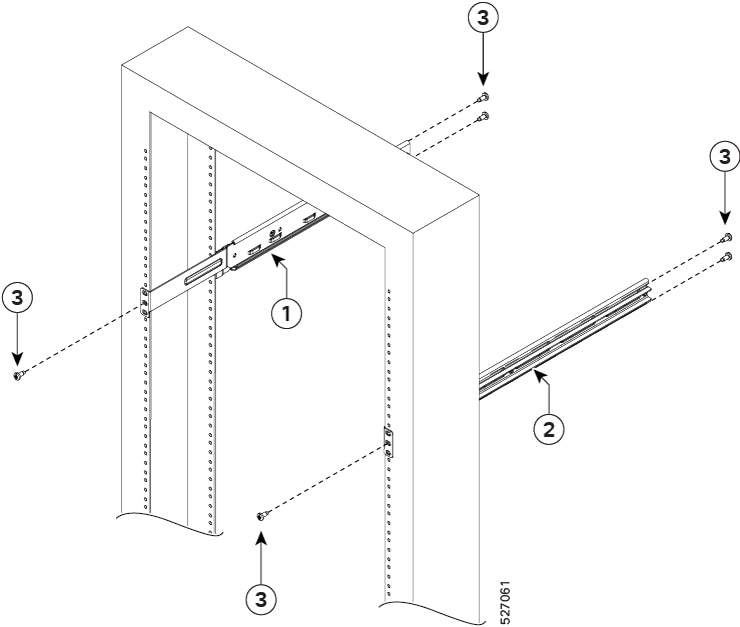
1
LH slider assembly (800-50378-01)
2
RH slider assembly (800-50377-01)
3
Screws (48-101524-01)
-
Attach the rack-mount brackets and the cable management to the router as follows:
-
The router has port-side intake modules, position the router so that its ports are facing the cold aisle.
-
Position the bracket ears facing front rack-mount, on the side of the chassis so that the holes are aligned.
-
Use sixteen M4 screws to attach the brackets to the chassis. Tighten the M4 screws to 13.3 inch-pounds (1.5 Nm).
Figure 21. Installing rack-mount brackets in the front 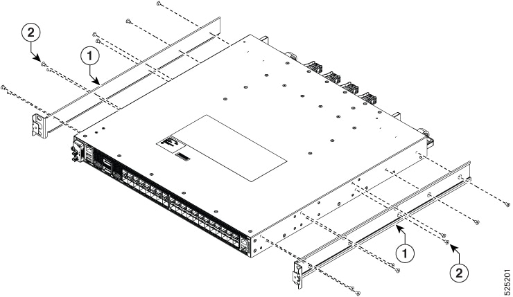
1
LH rail bracket (700-131280-01)
2
RH rail bracket (700-131279-01)
3
Screws (48-101238-01)
-
-
Place the router with slider bracket assembly on the 19-inch 2-post rack.
Figure 22. Installing the router with slider bracket assembly on the 19-inch 2-post rack 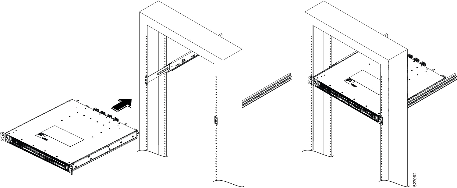
-
Install the cable mangement with 19-inch 2-post rack mount brackets in the front.
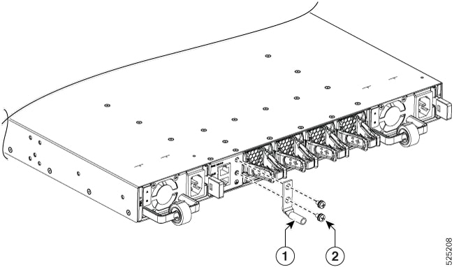
Figure 23. Installing cable management with 19-inch 2- post rack-mount brackets in the front 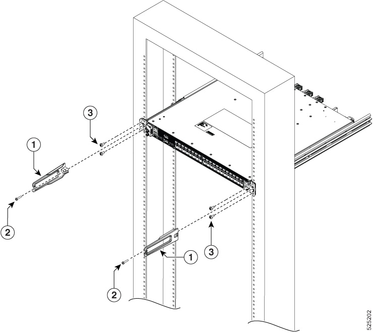
1
Cable management (700-05613-01)
2
Screws (48-0654-01)
3
Screws (48-101524-01)
-
Install the router onto the 2-post rack as follows:
-
Lift and position the router into position between the two rack posts.
-
Move the router until the rack-mount brackets come in contact with the two rack posts.
-
Hold the chassis at level and have another while the second person inserts two screws 12-24 in each of the two rack-mount brackets (using a total of four screws) and into the cage nuts or threaded holes in the vertical rack-mounting rails.
-
Tighten the 12-24 screws to 30 in-lb (3.39 N.m).
-
Cisco 8011-32Y8L2H2FH on the 19-inch 4-post rack
-
Install Left (L) and Right (R) slider assembly brackets on the 19-inch 4-post rack.
Figure 24. Installing L & R slider assembly brackets on the 19-inch 4-post rack 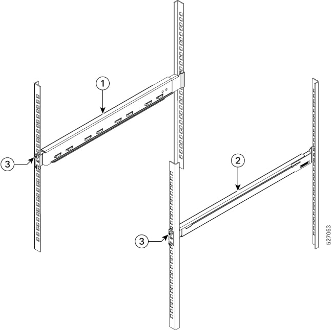
1
LH four-post slider assembly (800-50376-01)
2
RH four-post slider assembly (800-50375-01)
3
Screws (48-101524-01)
-
Attach the rack-mount brackets and the cable management to the router as follows:
-
The router has port-side intake modules, position the router so that its ports are facing the cold aisle.
-
Position the bracket ears facing front rack-mount, on the side of the chassis so that the holes are aligned.
-
Use sixteen M4 screws to attach the brackets to the chassis. Tighten the M4 screws to 13.3 inch-pounds (1.5 Nm).
Figure 25. Installing rack-mount brackets in the front
1
LH rail bracket (700-131280-01)
2
RH rail bracket (700-131279-01)
3
Screws (48-101238-01)
-
-
Place the router with slider bracket assembly on the 19-inch 4-post rack.
Figure 26. Installing the router with slider bracket assembly on the 19-inch 4-post rack 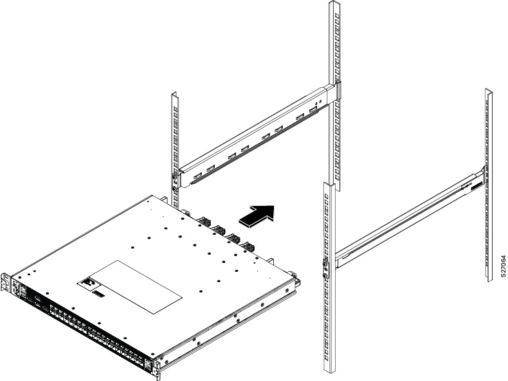
-
Install the cable management with 19-inch 4-post rack-mount brackets in the front.
Figure 27. Installing cable management with 19-inch 4-post rack-mount brackets in the front 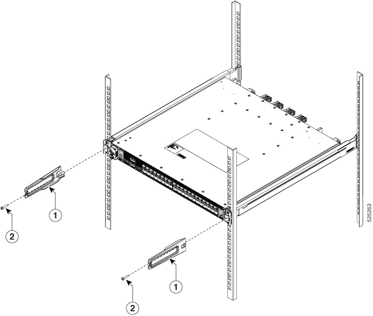
1
Cable management (700-05613-01)
2
Screws (48-0654-01)
-
Install the router onto the 4-post rack as follows:
-
Lift and position the router into position between the four rack posts.
-
Move the router until the rack-mount brackets come in contact with the four rack posts.
-
Hold the chassis at level and have another while the second person inserts two screws 12-24 in each of the four rack-mount brackets (using a total of four screws) and into the cage nuts or threaded holes in the vertical rack-mounting rails.
-
Tighten the 12-24 screws to 30 in-lb (3.39 N.m).
-
Cisco 8011-32Y8L2H2FH on the 21-inch 2-post rack
-
Install the Left (L) and Right (R) slide assembly brackets on the 21-inch 2-post rack.
Figure 28. Installing L & R slider assembly brackets on the 21-inch 2-post rack 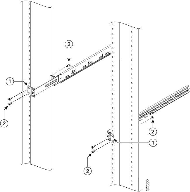
1
21-inch ETSI adapter (700-112689-01)
2
Screws (48-101524-01)
-
Install the cable management with 21-inch 2-post rack mount brackets in the front.
Figure 29. Installing cable management with 21-inch 2-post rack-mount brackets in the front 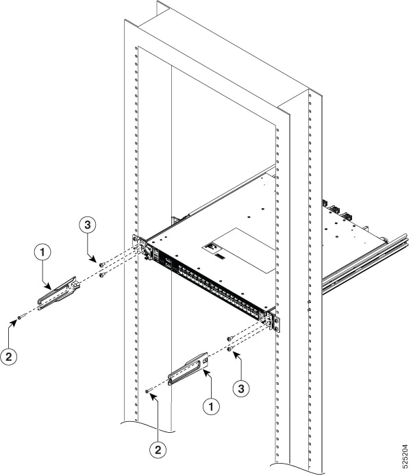
1
Cable management (700-05613-01)
2
Screws (48-0654-01)
3
Screws (48-101524-01)
-
Install the router onto the 2-post rack as follows:
-
Lift and position the router into position between the two rack posts.
-
Move the router until the rack-mount brackets come in contact with the two rack posts.
-
Hold the chassis at level and have another while the second person inserts two screws 12-24 in each of the two rack-mount brackets (using a total of four screws) and into the cage nuts or threaded holes in the vertical rack-mounting rails.
-
Tighten the 12-24 screws to 30 in-lb (3.39 N.m).
-
Cisco 8011-32Y8L2H2FH on the 21-inch 4-post rack
-
Install the Left (L) and Right (R) slider assembly brackets on the 21-inch 4-post rack.
Install the cable management with 21-inch 4-post rack mount brackets in the front.
Figure 30. Installing L & R slider assembly brackets on the 21-inch 4-post rack 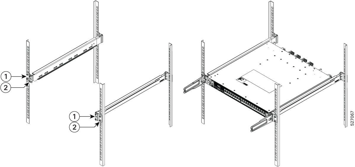
1
21-inch ETSI adapter (700-112689-01)
2
Screws (48-101524-01)
-
Install the router onto the 4-post rack as follows:
-
Lift and position the router into position between the four rack posts.
-
Move the router until the rack-mount brackets come in contact with the four rack posts.
-
Hold the chassis at level and have another while the second person inserts two screws 12-24 in each of the four rack-mount brackets (using a total of four screws) and into the cage nuts or threaded holes in the vertical rack-mounting rails.
-
Tighten the 12-24 screws to 30 in-lb (3.39 N.m).
-
Cisco 8011-32Y8L2H2FH on the 23-inch 2-post rack
-
Install the Left (L) and Right (R) slider assembly brackets on the 23-inch 2-post rack.
Figure 31. Installing L & R slider assembly brackets on the 23-inch 2-post rack 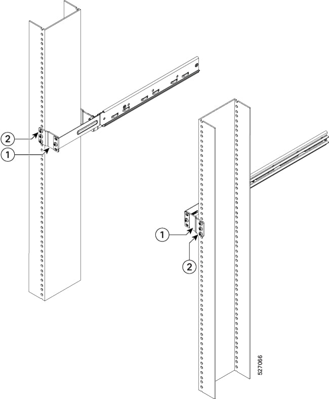
1
23-inch adapter (700-112688-01)
2
Screws (48-101524-01)
-
Install the cable management with 23-inch 2-post rack mount brackets in the front.
Figure 32. Installing cable management with 23-inch 2-post rack-mount brackets in the front 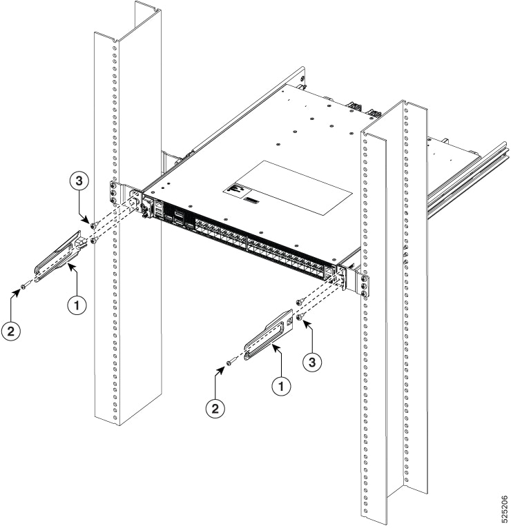
1
Cable management (700-05613-01)
2
Screws (48-0654-01)
3
Screws (48-101524-01)
-
Install the router onto the 2-post racks as follows:
-
Lift and position the router into position between the two rack posts.
-
Move the router until the rack-mount brackets come in contact with the two rack posts.
-
Hold the chassis at level and have another while the second person inserts two screws 12-24 in each of the two rack-mount brackets (using a total of four screws) and into the cage nuts or threaded holes in the vertical rack-mounting rails.
-
Tighten the 12-24 screws to 30 in-lb (3.39 N.m).
-
Cisco 8011-32Y8L2H2FH on the 23-inch 4-post rack
-
Install the Left (L) and Right (R) slider assembly brackets on the 23-inch 4-post rack.
Install the cable management with 23-inch 4-post rack mount brackets in the front.
Figure 33. Installing L & R slider assembly brackets on 23-inch 4-post rack 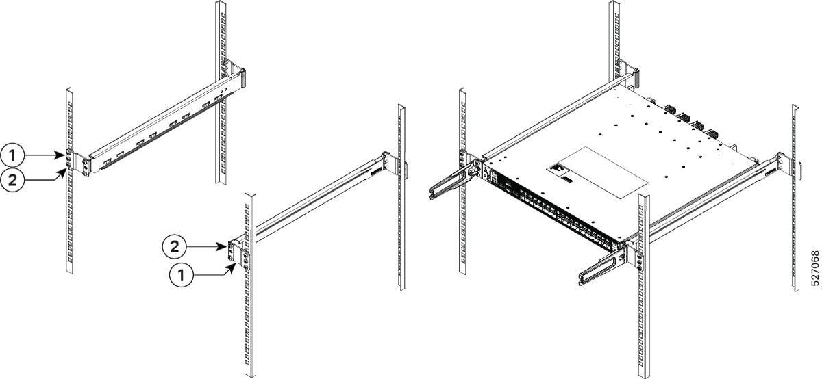
1
23-inch adapter (700-112688-01)
2
Screws (48-101524-01)
-
Install the router onto the 4-post rack as follows:
-
Lift and position the router into position between the four rack posts.
-
Move the router until the rack-mount brackets come in contact with the four rack posts.
-
Hold the chassis at level and have another while the second person inserts two screws 12-24 in each of the four rack-mount brackets (using a total of four screws) and into the cage nuts or threaded holes in the vertical rack-mounting rails.
-
Tighten the 12-24 screws to 30 in-lb (3.39 N.m).
-
Cisco 8011-12G12X4Y Router
-
Attach the rack-mount brackets and the cable management to the router as follows:
-
The router has port-side intake modules, position the router so that its ports are facing the cold aisle.
-
Position the bracket ears facing front or middle rack-mount, on the side of the chassis so that the holes are aligned.
-
Use four M3 screws to attach the brackets to the chassis.
-
Repeat Steps 1b and 1c with the other rack-mount bracket on the other side of the router.
-
Use four No. 12-24 screws and mount the router to the rack.
Figure 34. Installing 19 inch Rack-Mount Brackets in the Front 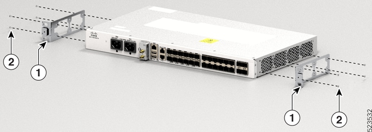
1
Mount Bracket
2
Screw
Figure 35. Installing Cable Management and 19 inch Rack-Mount Brackets in the Front 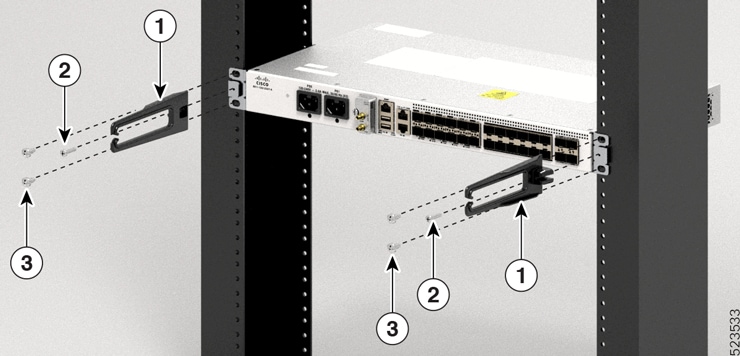
1
Cable Management Bracket
2
Cable Management Screw
3
Screw
Figure 36. Installing 19 inch Rack-Mount Brackets in the Middle 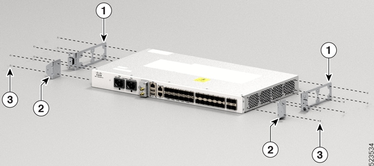
1
Mount Bracket
2
Cable Management Bracket
3
Screw
Figure 37. Installing Cable Management and 19 inch Rack-Mount Brackets in the Middle 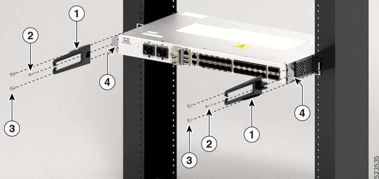
1
Cable management bracket
2
Cable management screw
3
Screw
4
Bracket
Figure 38. Installing 23 inch Rack-Mount Brackets in the Front 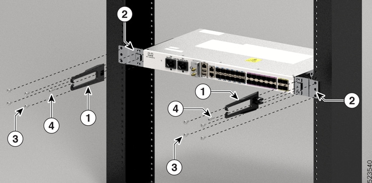
1
Mount Bracket
2
Screw
Figure 39. Installing 23 inch Rack-Mount Brackets in the Middle 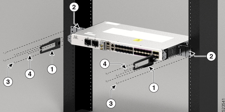
1, 2
Mount Bracket
3
Screw
Figure 40. Installing Cable Management and ETSI Rack-Mount Brackets in the Front 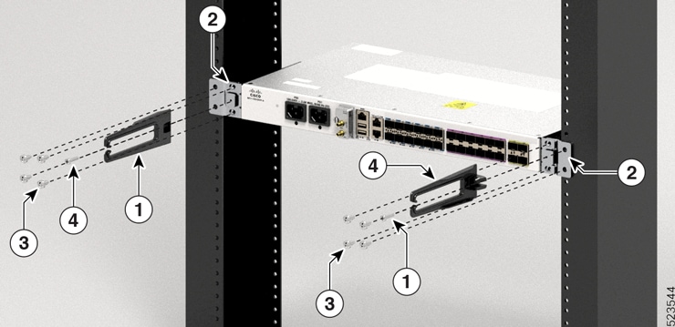
1
Cable Management Bracket
2
Cable Management Screw
3
Screw
Figure 41. Installing Cable Management and ETSI Rack-Mount Brackets in the Middle 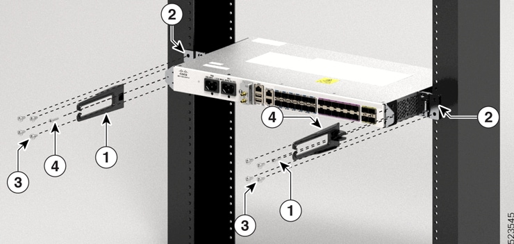
1
Cable Management Bracket
2
Cable Management Screw
3
Screw
-
-
Install the router onto the 2-post rack as follows:
-
Lift and position the router into position between the two rack posts.
-
Move the router until the rack-mount brackets come in contact with the two rack posts.
-
Hold the chassis at level and have another while the second person inserts two screws 12-24 in each of the two rack-mount brackets (using a total of four screws) and into the cage nuts or threaded holes in the vertical rack-mounting rails.
-
Tighten the 12-24 screws to 30 in-lb (3.39 N.m).
-
Wall Mount
Note |
This feature is supported only for the Cisco 8011-4G24Y4H-I Router. |
The router is shipped with wall mounting brackets that are to be secured on the sides of the router.
Install the wall mounting brackets and cable guides on to the chassis before you mount the chassis on the wall.
Install Wall Brackets
-
Remove the wall mounting brackets from the accessory kit and position them beside the router. You can install the brackets as shown in the figure.
Figure 42. Install Wall Mount Brackets 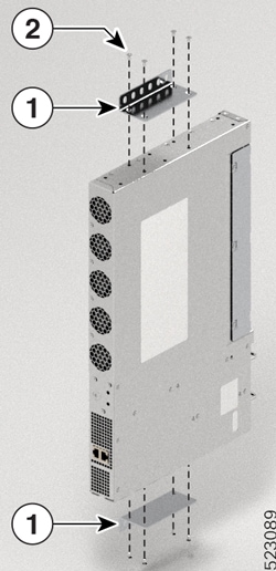
1
Wall Mount Bracket
2
Screw
-
Secure the bracket to the router with the recommended maximum torque of 13.3 inch-pounds (1.5 newton meters) using M4 flat head screws.
Wall Mount the Router
Caution |
Before mounting the router, ensure that all unused holes at the sides of the router are always protected by screws. |
Note |
While you mount the router, always ensure that the power supplies are at the bottom position. |
For the support of the router and cables, ensure that the router is attached securely to wall studs or to a firmly attached plywood mounting backboard.
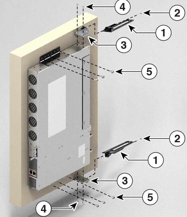
|
1 |
Cable Management |
|
2 |
Cable Management Screw |
|
3 |
Cable Management Bracket |
|
4 |
Cable Management Bracket Screw |
|
5 |
Wall Mount Bracket Screw |


 Feedback