LEDs
The Cisco 8010 Large Density Density Router LEDs are similar for most of the variants, and any differences between the routers are specifically called out.
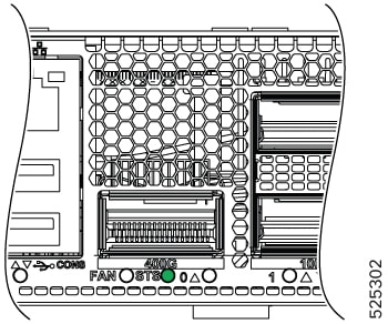
Router LEDs
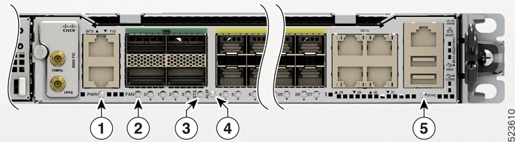
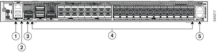
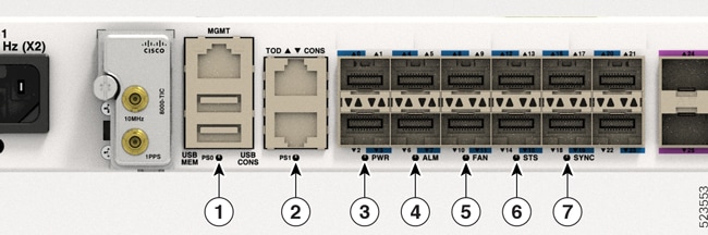
All the data port LEDs in the Cisco router are at the front panel.
|
LED Label |
Color |
Status |
|---|---|---|
|
STS |
Off |
The module is powered-off (set by hardware); only standby power mode is available. |
|
Flashing Amber (Slow) |
The module is booting up (set by IOFPGA). |
|
|
Flashing Amber (Fast) |
The module is booting up (set by BIOS), shutting down, or is being reloaded. |
|
|
Amber |
Host kernel is booted and is ready to start SysAdmin VM. |
|
|
Green |
The module is operational and has no active major or critical alarms. |
|
|
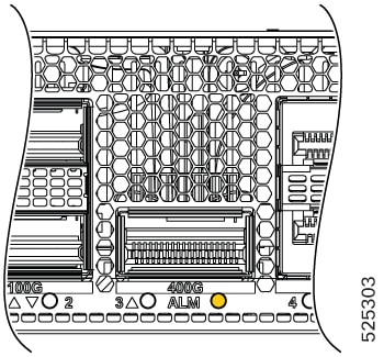
ALM |
Off |
No alarm |
|
Red |
Critical alarm - system scope, critical temperature. |
|
|
Flashing Red |
Critical alarm - Relating to voltage rail failures. |
|
|
Amber |
Major alarm - system-scope. |
|
|
Flashing Amber |
Minor alarm - system-scope |
|
|
SYNC |
Off |
Time core clock synchronization is disabled or in free-running state. |
|
Green |
Time core is synchronized to an external source including IEEE1588. |
|
|
Flashing Green |
System is in Synchronous Ethernet mode. |
|
|
Amber |
Acquiring state or Holdover: Time core is in acquiring state or holdover mode. |
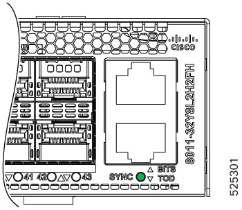
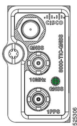
GNSS LEDs
 Note |
GNSS LEDs are available only on the Cisco 8011-32Y8L2H2FH Router. |
|
LED |
Color |
Status |
|---|---|---|
|
GNSS |
Off |
GNSS is not configured. |
|
Green |
GNSS normal state. Self-survey is complete. |
|
|
Amber |
Auto holdover. |
|
|
Red |
Power up. GNSS is not tracking any satellite. |
|
|
Flashing green |
Learning state is normal. Self-survey is not completed. |
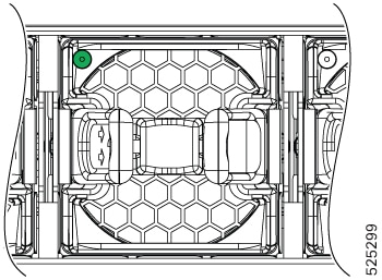
Fan Module LEDs
|
LED |
Color |
Status |
|---|---|---|
|
STATUS |
Green |
Fan operating normally. |
|
Red |
Fan failure. |
|
|
Off |
Fan is not receiving power. |
Fan Assembly LEDs
The Cisco 8011-4G24Y4H-I Router contains:
-
5 fixed fans at the back panel.
-
Fan modules are numbered from left to right as Fan 4 to Fan 0.
The Cisco 8011-32Y8L2H2FH Router contains:
-
4 modular fans at the back panel.
-
Fan modules are numbered from left to right as Fan 3 to Fan 0.
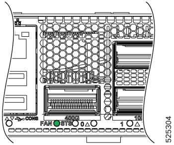
There is an LED on the front panel of the router that reflect the different status of the fans.
|
LED Label |
Color |
Status |
|---|---|---|
|
FAN |
Off |
Fan tray is not receiving power. |
|
Green |
Fans are operating normally. |
|
|
Amber |
Single fan failure. |
|
|
Red |
More than one fan failure. |
Power Supply LEDs
|
State |
Color - Green (AC/DC power status) |
Color - Amber (Power supply status) |
|---|---|---|
|
Blinking |
AC power OK, DC output not enabled, sleep mode, 12V standby is ON. |
|
|
Solid On |
DC output OK regardless of warning. |
|
|
Off |
|
No failures or warnings |
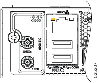
Power Status LEDs
|
LED Label |
Color |
Status |
|---|---|---|
|
PWR |
Off |
Sytem is powered off. |
|
Green |
All the power supplies are on and operating normally. |
|
|
Amber |
Standby FPGA upgrade is in progress (this is expected to take about three to five minutes). |
|
|
Red |
Power redundancy is lost due to a power feed failure or an internal power supply failure. |
SFP Port LEDs
|
LED Label |
Color |
Status |
|---|---|---|
|
STATUS |
Off |
Admin is down |
|
Green |
Link is up in 1/10/25G ports |
|
|
Yellow |
Fault or Error or Link Down |
Copper Port LEDs
Note |
Copper port LEDs are available only on the Cisco 8011-4G24Y4H-I Router. |
|
LED Label |
Color |
Status |
|---|---|---|
|
Left LED |
Green |
Link is up in 10/100/1000 Mbps |
|
Blinking Green |
Activity in 1G/100/10 Mbps |
|
|
Amber or Orange |
Fault/Error/Link is down |
|
|
Off |
Admin is down |
|
|
Right LED |
Green |
Link is up in full duplex |
Management Port LEDs
|
LED Label |
Color |
Status |
|---|---|---|
|
Left LED |
Green |
Link is up in 1000 Mbps |
|
Blinking Green |
Activity in 1000 Mbps |
|
|
Amber or Orange |
Link is up in 100/10Mbps |
|
|
Blinking Amber or Orange |
Activity in 100/10Mbps |
|
|
Off |
Link is down |
|
|
Right LED |
Off |
Unused |

 Feedback