
Hardware Features of Cisco 8000 Series Large and Medium Density Routers
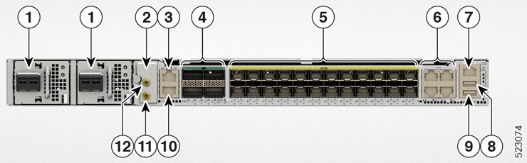
Cisco 8011-4G24Y4H-I Router
|
1 |
DC or AC PSU Power Module (PM0 and PM1) |
2 |
|
|
3 |
BITS port |
4 |
100G QSFP ports |
|
5 |
1/10/25G SFP ports |
6 |
Copper ports |
|
7 |
1G Ethernet Management port |
8 |
USB memory port |
|
9 |
USB Console port |
10 |
1PPS/Time of Day (ToD) port |
|
11 |
1PPS port |
12 |
10MHz port |
|
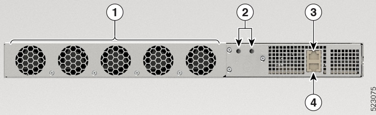
1 |
Fixed Fan Modules |
2 |
Grounding Lug Holes |
|
3 |
Alarm port |
4 |
RS232 Console port |
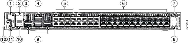
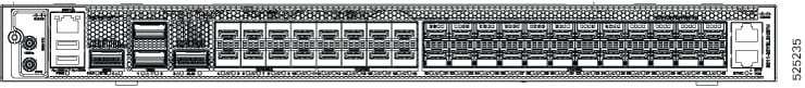
Cisco 8011-32Y8L2H2FH Router
|
1 |
|
2 |
10/100/1000M Ethernet Management port |
|
3 |
USB memory port |
4 |
100G QSFP ports |
|
5 |
10/25/50G SFP ports |
6 |
1/10/25G SFP ports |
|
7 |
BITS port |
8 |
1PPS/Time of Day (ToD) port |
|
9 |
400G QSFP ports |
10 |
USB console port |
|
11 |
1PPS port |
12 |
10MHz port |
|
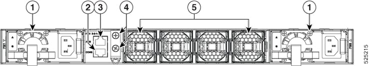
1 |
DC or AC PSU power module (PM0 and PM1) |
2 |
RS232 console port |
|
3 |
Alarm port |
4 |
Grounding lug holes |
|
5 |
Fan modules (0 to 3) |
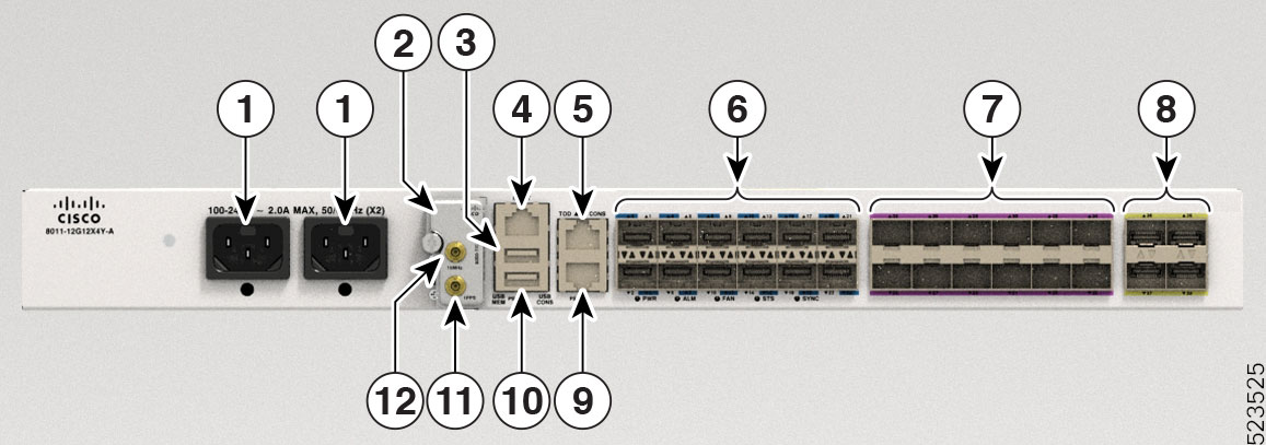
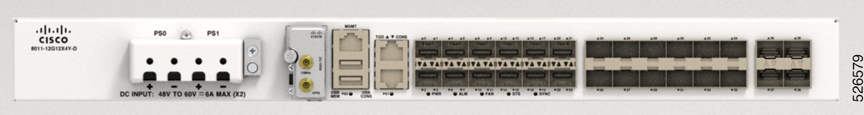
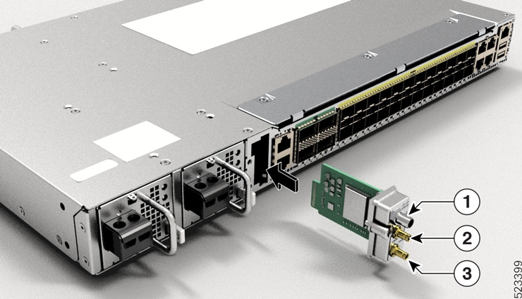
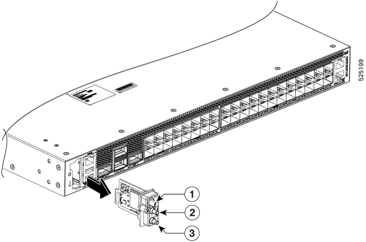
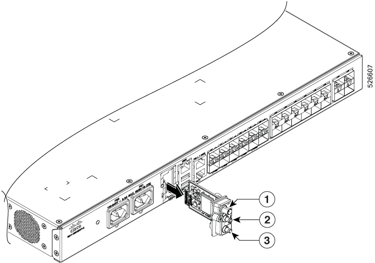
Cisco 8011-12G12X4Y-A Router
|
1 |
AC PSU PS0/PS1 PM |
2 |
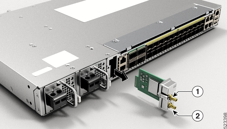
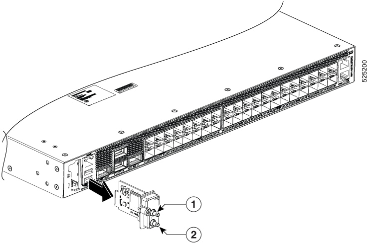
8000-TIC (by default) or 8000-TIC-GNSS (optional) |
|
3 |
USB Memory port |
4 |
Management port |
|
5 |
1PPS/Time of Day (ToD) port |
6 |
1G CSFP SFP ports |
|
7 |
1/10G SFP+ ports |
8 |
1/10/25G SFP28 ports |
|
9 |
RS232 Console port |
10 |
USB Console port |
|
11 |
1PPS |
12 |
10MHz |
|
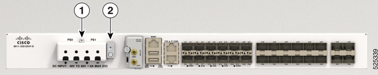
1 |
DC PSU PS0/PS1 PM |
2 |
Surge pin |
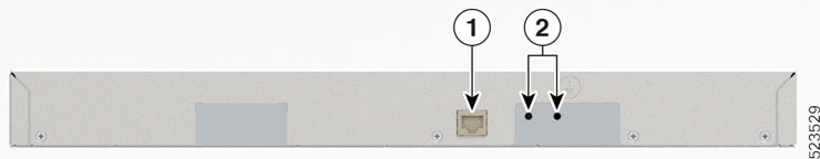
|
1 |
Alarm port |
2 |
Lug Holes |
For temperature and physical specifications, see the Cisco 8010 Series Routers Data Sheet.

 Feedback