Increase Memory Capacity of ASR 9000 RSP5-TR or ASR 9900 RP3-TR
Users can increase the memory capacity of an ASR 9000 RSP5-TR (PID: A9K-RSP5-TR) or ASR 9900 RP3-TR (PID: A99-RP3-TR) card from 16GB to 24GB by inserting an additional 8GB DIMM (PID: A9K-MEM-UPG-8G). Use only Cisco supported DIMM (dual in-line memory module).
 Note |
While performing the upgrade, avoid contact with open circuit board components. Handle the card and make contact only with the metal frame. |
Procedure
| Step 1 |
Attach an ESD-preventive wrist or ankle strap and follow its instructions for use. Ensure that the wrist strap is correctly grounded to prevent electrostatic damage to the DIMM or the boards (ASR 9000 RSP5-TR or ASR 9900 RP3-TR). |
||||||||||
| Step 2 |
Place the ASR 9000 RSP5-TR or ASR 9900 RP3-TR card on an antistatic mat so that the faceplate is nearest to you. |
||||||||||
| Step 3 |
(Only ASR 9000 RSP5-TR) Except for the 3 screws at the side end of the metallic cover, remove all the other 13 screws from the metallic cover to get access to the PCB of the ASR 9000 RSP5-TR/ASR 9900 RP3-TR cards. See the image below: 
|
||||||||||
| Step 4 |
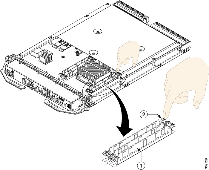
(Only ASR 9900 RP3-TR) There is no need to remove the metallic cover as the DIMM sockets are directly exposed. |
||||||||||
| Step 5 |
Locate the DIMM sockets on the card. Please insert the DIMM only in the socket that is indicated in the image. 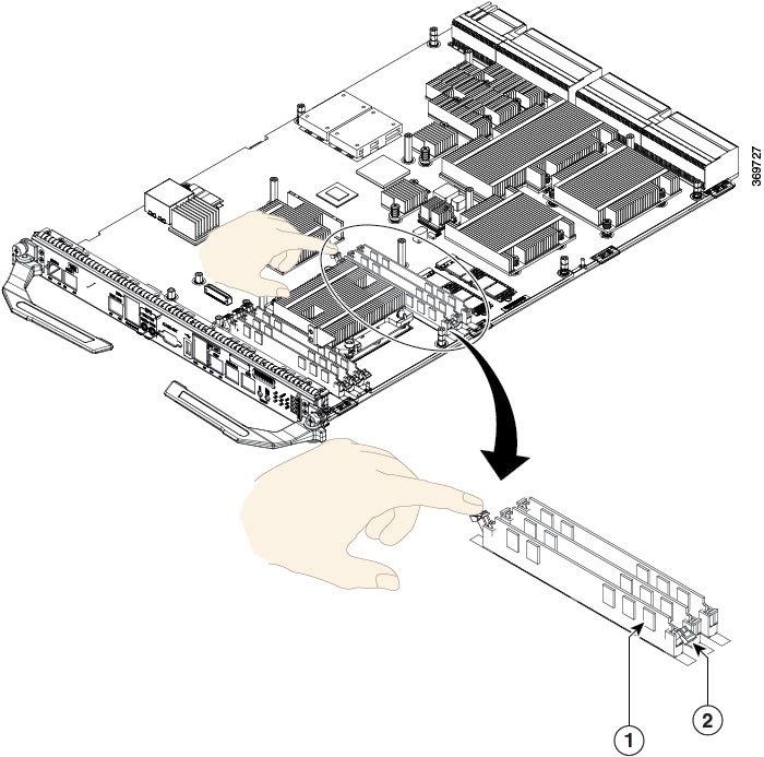
|
||||||||||
| Step 6 |
Pull down the socket release levers. For an RP3 card, use a pointed object to gently push the socket lever outward, to release the lever. See the image below: 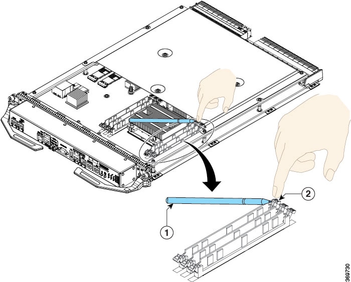
|
||||||||||
| Step 7 |
Remove the new DIMM from its protective antistatic bag. |
||||||||||
| Step 8 |
Grasp the edges of the DIMM only. Do not touch the integrated circuit devices on the DIMM, the metal traces, or fingers, along the edge of the DIMM, or the pins in the DIMM socket. |
||||||||||
| Step 9 |
To position the DIMM for insertion, orient it at the same angle as the DIMM socket. The single notch (key) on the bottom edge of the module ensure that the DIMM edge connector is registered properly in the socket. See the image below: 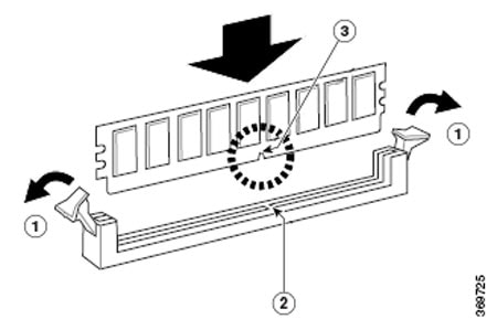
|
||||||||||
| Step 10 |
Gently insert the DIMM into the socket and push until the DIMM snaps into place and the release lever is flush against the side of the socket. See the figure below: 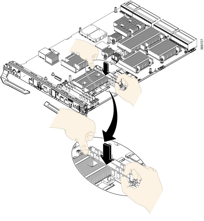 |
||||||||||
| Step 11 |
Verify that the release lever is flush against the side of the socket. If it is not, the DIMM might not be seated properly. On a socket with dual release levers, both levers should be flush against the sides of the DIMM. See the image below: 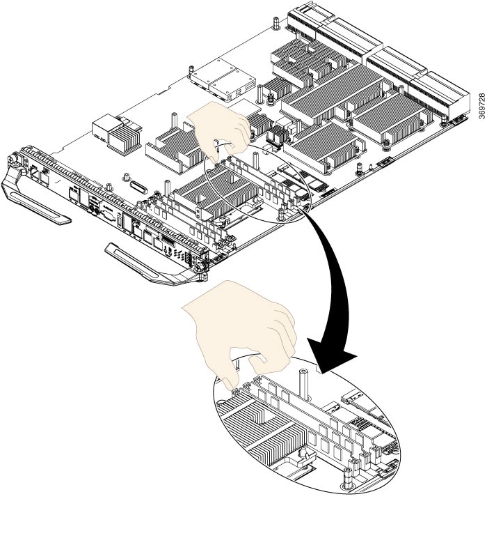 |
||||||||||
| Step 12 |
(Only ASR 9000 RSP5-TR) Secure the metallic cover on the card and tighten the screws:
|
||||||||||
| Step 13 |
To identify the DIMM, no software upgrade or other changes are required. To verify the size of the memory that has been upgraded, start the system and execute the show system resource command in the admin mode. Check the Physical Available column to view the upgraded memory size against the host row: |
 Feedback