Overview

Overview

This guide covers all Cisco HX240c Hybrid and All-Flash models.

The following table lists the minimum levels of Cisco HyperFlex software required for the small form-factor (SFF) 2.5-inch drives versions and the large form-factor (LFF) 3.5-inch drives version.


Note

The software requirements given below are for the base chassis. Certain configurable components might require later software levels, as noted in this guide.


Table 1. HX240c M5 System Minimum Software Requirements

System Version

Cisco HyperFlex Software Minimum Level

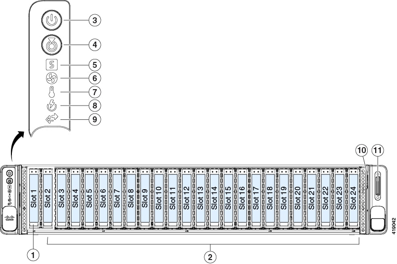
HX240c M5 SFF Hybrid

(HX240C-M5SX)

2.6.1a or later

HX240c M5 SFF All-Flash

(HXAF240C-M5SX)

2.6.1a or later

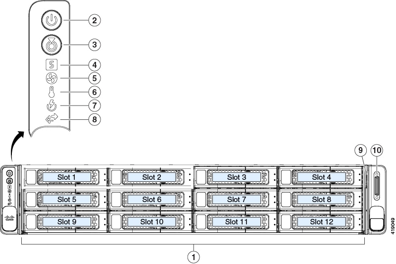
HX240c M5 LFF Hybrid

(HX240C-M5L)

3.0.1 or later

Cisco HyperFlex Systems Related Documentation

Links for related Cisco HyperFlex Systems documentation such as the Getting Started Guide, Administration Guide, and Release Notes are listed in the Cisco HyperFlex Systems Documentation Roadmap.

HX240c SFF Drives External Features

HX240c SFF Drives Front Panel Features

For definitions of LED states, see Front-Panel LEDs.

Figure 1. SFF Front Panel

1

Drive bay 1: Housekeeping SSD for logs

7

Temperature status LED

2

2.5-inch drive bays 2 – 24:

  • Hybrid HX240C-M5SX: 6 to 23 persistent data HDDs

  • All-Flash HXAF240C-M5SX: 6 to 23 persistent data SSDs

8

Power supply status LED

3

Power button/power status LED

9

Network link activity LED

4

Unit identification button/LED

10

Pull-out asset tag

5

System status LED

11

KVM connector (used with KVM cable that provides one DB-15 VGA, one DB-9 serial, and two USB connectors)

6

Fan status LED

-

HX240c SFF Drives Rear Panel Features

For definitions of LED states, see Rear-Panel LEDs.

Figure 2. SFF Rear Panel

1

PCIe riser 1 (PCIe slot 1, 2, 3)

7

USB 3.0 ports (two)

2

PCIe riser 2B (PCIe slots 4, 5, 6)

8

Dual 1-Gb/10-Gb Ethernet ports (LAN1 and LAN2)

The dual LAN ports can support 1 Gbps and 10 Gbps, depending on the link partner capability.

3

Rear drive bay 25: Caching SSD

9

VGA video port (DB-15 connector)

4

Power supplies (two, redundant as 1+1)

10

1-Gb Ethernet dedicated management port

5

Threaded holes for dual-hole grounding lug.

11

Serial port (RJ-45 connector)

6

Modular LAN-on-motherboard (mLOM) card slot (x16) for Cisco VIC card

12

Rear unit identification button/LED

HX240c LFF Drives External Features

HX240c LFF Drives Front Panel Features

For definitions of LED states, see Front-Panel LEDs.

Figure 3. LFF Front Panel

1

3.5-inch drive bays 1 – 12:

  • Hybrid HX240C-M5L: 6 to 12 persistent data HDDs

7

Power supply status LED

2

Power button/power status LED

8

Network link activity LED

3

Unit identification button/LED

9

Pull-out asset tag

4

System status LED

10

KVM connector (used with KVM cable that provides one DB-15 VGA, one DB-9 serial, and two USB connectors)

5

Fan status LED

-

6

Temperature status LED

-

HX240c LFF Drives Rear Panel Features

For definitions of LED states, see Rear-Panel LEDs.

Figure 4. LFF Rear Panel

1

PCIe riser 1 (PCIe slot 1, 2, 3)

8

USB 3.0 ports (two)

2

PCIe riser 2B (PCIe slots 4, 5, 6)

9

Dual 1-Gb/10-Gb Ethernet ports (LAN1 and LAN2)

The dual LAN ports can support 1 Gbps and 10 Gbps, depending on the link partner capability.

3

Rear drive bay 13: Caching SSD

10

VGA video port (DB-15 connector)

4

Rear drive bay 14: Housekeeping SSD for logs

11

1-Gb Ethernet dedicated management port

5

Power supplies (two, redundant as 1+1)

12

Serial port (RJ-45 connector)

6

Threaded holes for dual-hole grounding lug.

13

Rear unit identification button/LED

7

Modular LAN-on-motherboard (mLOM) card slot (x16) for Cisco VIC card

HX240c SFF Drives Serviceable Component Locations

This topic shows the locations of the field-replaceable components and service-related items.


Note

The internal component locations are the same for the SFF and LFF versions of the node unless otherwise noted. The functions of the drives differ in SFF and LFF versions, as described in this document.


Figure 5. SFF Serviceable Component Locations

1

2.5-inch drive bays 2 – 24:

  • Hybrid HX240C-M5SX: 6 to 23 persistent data HDDs

  • All-Flash HXAF240C-M5SX: 6 to 23 persistent data SSDs

10

Rear drive bay 25: Caching SSD

2

Drive bay 1: Housekeeping SSD for logs

11

PCIe riser 2B (PCIe slots 4, 5, 6)

3

Cooling fan modules (six, hot-swappable)

12

Micro-SD card socket on PCIe riser 1

4

DIMM sockets on motherboard (up to 12 per CPU)

Not visible under air baffle in this view.

13

PCIe riser 1 (PCIe slot 1, 2, 3)

5

CPUs and heatsinks (two)

Not visible under air baffle in this view.

14

Modular LOM (mLOM) card bay on chassis floor (x16 PCIe lane), not visible in this view

6

Internal, vertical USB 3.0 port on motherboard

15

Cisco modular storage controller HBA slot (dedicated PCIe slot)

7

Mini-storage module for SATA M.2 SSD boot drive

16

RTC battery, vertical socket on motherboard

8

PCIe cable connector on PCIe riser 2B for rear-loading NVMe SSD

17

Securing clips for GPU cards on air baffle

9

Power supplies (hot-swappable when redundant as 1+1)

-

HX240c LFF Drives Serviceable Component Locations

This topic shows the locations of the field-replaceable components and service-related items for Hybrid HX240C-M5L.


Note

The internal component locations are the same for the SFF and LFF versions of the node unless otherwise noted. The functions of the drives differ in SFF and LFF versions, as described in this document.


Figure 6. LFF Serviceable Component Locations

1

3.5-inch drive bays 1 – 12:

  • Hybrid HX240C-M5L: 6 to 12 persistent data HDDs

10

Rear drive bay 13: Caching SSD

2

Cooling fan modules (six, hot-swappable)

11

PCIe riser 2B (PCIe slots 4, 5, 6)

3

DIMM sockets on motherboard (up to 12 per CPU)

Not visible under air baffle in this view.

12

Micro-SD card socket on PCIe riser 1

4

CPUs and heatsinks (two)

Not visible under air baffle in this view.

13

PCIe riser 1 (PCIe slot 1, 2, 3)

5

Internal, vertical USB 3.0 port on motherboard

14

Modular LOM (mLOM) card bay on chassis floor (x16 PCIe lane), not visible in this view

6

Mini-storage module for SATA M.2 SSD boot drive

15

Cisco modular storage controller HBA slot (dedicated PCIe slot)

7

PCIe cable connector on PCIe riser 2B for rear-loading NVMe SSD

16

RTC battery, vertical socket on motherboard

8

Power supplies (hot-swappable when redundant as 1+1)

17

Securing clips for GPU cards on air baffle

9

Rear drive bay 14: Housekeeping SSD for logs

-

Summary of Node Features

The following table lists a summary of node features.

Feature

Description

Chassis

Two rack-unit (2RU) chassis

Central Processor

Two identical CPUs from the Intel Xeon Processor Scalable Family.

Memory

24 DDR4 DIMM sockets on the motherboard (12 each CPU)

Multi-bit error protection

Multi-bit error protection is supported

Baseboard management

BMC, running Cisco Integrated Management Controller (Cisco IMC) firmware.

Depending on your Cisco IMC settings, Cisco IMC can be accessed through the 1-Gb dedicated management port, the 1-Gb/10-Gb Ethernet LAN ports, or a Cisco virtual interface card.

Network and management I/O

Rear panel:

  • One 1-Gb Ethernet dedicated management port (RJ-45 connector)

  • Two 1-Gb/10-Gb BASE-T Ethernet LAN ports (RJ-45 connectors)

    The dual LAN ports can support 1 Gbps and 10 Gbps, depending on the link partner capability.

  • One RS-232 serial port (RJ-45 connector)

  • One VGA video connector port (DB-15 connector)

  • Two USB 3.0 ports

Front panel:

  • One front-panel keyboard/video/mouse (KVM) connector that is used with the KVM cable, which provides two USB 2.0, one VGA, and one DB-9 serial connector.

Modular LOM

One dedicated socket (x16 PCIe lane) that can be used to add a Cisco VIC mLOM card for additional rear-panel connectivity.

Power

One or two power supplies, redundant as 1+1 when two power supplies are present. Several options are available:

  • AC power supplies 1050 W AC each

  • AC power supplies 1600 W AC each

  • DC power supplies 1050 W DC each

Do not mix power supply types or wattages in the node.

ACPI

The advanced configuration and power interface (ACPI) 4.0 standard is supported.

Cooling

Six hot-swappable fan modules for front-to-rear cooling.

PCIe I/O

Six horizontal PCIe expansion slots on two PCIe riser assemblies.

InfiniBand

The PCIe bus slots in this node support the InfiniBand architecture.

Storage, external loading:

Small form-factor (SFF) drive versions

Drives are installed into front- and rear-panel drive bays.

  • Front drive bay 1 is dedicated to one Housekeeping SSD for logs.

  • Front drive bays 2 - 24 are dedicated to persistent data drives:

    • Hybrid HX240C-M5SX: 6 to 23 HDDs.

    • All-Flash HXAF240C-M5SX: 6 to 23 SSDs.

  • Rear drive bay 25 is dedicated to one Caching SSD.

Storage, external loading:

Large form-factor (LFF) drive versions

Drives are installed into front- and rear-panel drive bays.

  • Front drive bays 1 - 12 are dedicated to persistent data drives:

    • Hybrid HX240C-M5L: 6 to 12 HDDs.

  • Rear drive bay 13 is dedicated to one Caching SSD.

  • Rear drive bay 14 is dedicated to one Housekeeping SSD for logs.

Storage, internal

(all versions)

The node has these internal storage options:

  • Mini-storage module that supports a SATA M.2 SSD Boot drive.

  • One Micro-SD card socket on PCIe riser 1.

  • One USB 3.0 port on the motherboard.

Storage management

The node has a dedicated internal PCIe slot that supports an HBA storage controller.

Integrated video

Integrated VGA video.