Securing Network Infrastructure in VXLAN BGP EVPN Data Centers
Available Languages
Bias-Free Language
The documentation set for this product strives to use bias-free language. For the purposes of this documentation set, bias-free is defined as language that does not imply discrimination based on age, disability, gender, racial identity, ethnic identity, sexual orientation, socioeconomic status, and intersectionality. Exceptions may be present in the documentation due to language that is hardcoded in the user interfaces of the product software, language used based on RFP documentation, or language that is used by a referenced third-party product. Learn more about how Cisco is using Inclusive Language.
- US/Canada 800-553-2447
- Worldwide Support Phone Numbers
- All Tools
 Feedback
 Feedback
Network Security Concepts in VXLAN BGP EVPN Data Centers
First Hop Security in VXLAN Fabrics
Data Plane Security in VXLAN Fabrics
Control Plane Security in VXLAN Fabrics
The data center network is the location for business applications and data. The applications include enterprise resource planning, customer relationship management, mainframe servers, data warehouse, business conferencing, database management, collaboration, storage systems, etc. The applications run daily business operations. If these applications are not accessible, the business operation is affected, which in turn hinders the business’s ability to deliver products or services to its customers. The valuable data processed and generated by business applications is an asset of the enterprise. The protection of the data is critical to protect intellectual property, privacy, and uninterrupted business operations. The network infrastructure provides connectivity between the user and the applications. If the network systems, such as routers and switches, have vulnerabilities that do not allow the network systems to forward packets, the user will lose access to the applications. Hence, it is imperative that the network infrastructure is implemented with security tools to ensure the availability of the network infrastructure. If the network infrastructure is compromised, then the applications depending on the network will not be accessible or also compromised.
The goal of this document is to educate on the importance of hardening your data center network infrastructure. This document focuses on the VXLAN BGP EVPN fabric network type, which is the focus of this document, on the Cisco Nexus 9000 NX-OS platform. The data center network infrastructure hardening using endpoint, data plane, and control plane protection mechanisms are also explained in this document. For each protection mechanism, the problem statement, benefits, and implementation steps are explained. The audience of this document is data center network architects implementing VXLAN BGP EVPN fabrics. It is assumed that the reader already has knowledge and experience with VXLAN BGP EVPN technology.
Network Security Concepts in VXLAN BGP EVPN Data Centers
CIA Triad
The CIA Triad is a foundational model which comprises core network security principles. The CIA is an acronym for Confidentiality, Integrity, and Availability. The CIA Triad provides a framework for designing, implementing, and evaluating security technologies, policies, procedures, standards, and controls. Any security solution is built to address confidentiality, integrity, or availability of the system or data.
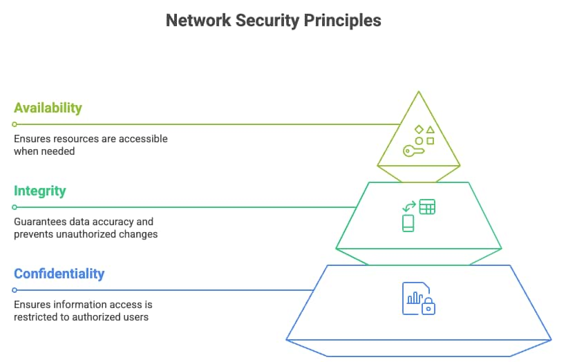
CIA Triad Principles
The confidentiality mechanisms are the only ones that allow authorized users or systems to view or access data in any phase of the data life cycle. The data life cycle encompasses the stages of data storage, transit, and processing. The basic goal of confidentiality is to prevent unauthorized access to the data. Common examples of how confidentiality is achieved are using encryption protocols such as TLS, SSH, or IPsec when data is in transit. Access control methods such as passwords and multi-factor authentication also provide confidentiality. Providing confidentiality to a data center network switch involves several measures, including encrypting data in transit, controlling login access, storing files in bootflash in encrypted format, and limiting access to file system or operating system commands. In an Ethernet data center network, packets can be encrypted as they are transmitted through the network using media access control security (MACsec), providing confidentiality. The implementation of Authentication, Authorization, and Accounting (AAA) using protocols such as RADIUS and TACACS+ controls access to network devices. While AAA helps ensure that only authorized users can access network resources, thereby supporting the confidentiality of sensitive information, it does not directly provide encryption. Confidentiality is primarily achieved through encryption of data in transit and at rest.
Integrity is the mechanism that ensures that any data in storage, transit, or processing has not been tampered with. Data with integrity is accurate, consistent, and unmodified. Common integrity techniques include hashing, checksums, digital signatures, access control (permissions), and audit logs to track changes. In a data center network infrastructure, SHA-256 hash checks are performed on configuration files, backups, and critical logs. Firmware and operating system software installed on computer or network nodes should contain digital signatures to ensure the files are from a trusted source. Integrity is critical in monitoring and auditing the data center network infrastructure, as real-time and reliable infrastructure logs, debugs, core dumps, and traces can only tell accurately the root cause of any network incident.
The availability of a system or data ensures access to it in a reliable and timely manner to the user. Installing redundant backup components and load balancing to multiple servers or links are network availability techniques. Availability in a network device is provided by having multiple route processors on a modular chassis. Server multihoming solutions such as virtual port-channel (vPC) provide active/active data plane connection to two upstream switches, providing connectivity to the application on the server even in case of a single link or upstream switch failure. Moving from a monolithic operating system architecture to a modular and distributed operating system architecture increases system availability by preventing a system reload due to a single process crash. In case of a process crash, only the process is restarted and brought back into service.
The CIA principles can be applied in multiple layers of a network system. A network system such as a router or switch at the fundamental layer consists of hardware and software. In a network device, the network routing function is divided into two layers: the control plane and data plane. The control plane protocols discover their neighbors, discover topology, learn routes, determine the best path to a destination network, and populate the routing table with the best route. The routing table is commonly known as the routing information base (RIB). The control plane is the brain of the network device because its function is decision-making. Examples of control plane protocols on a network device are OSPF, ISIS, BGP, EIGRP, and RIP. The control plane must be protected as it decides where to send the packet, and if the network does not know where to send the packet or sends the packet incorrectly, then connectivity to the application is lost. The CIA principles also apply to the control plane. The network device must be available so that administrators can access it to configure, monitor, and troubleshoot. The routing protocol should discover and exchange secure network reachability information with trusted devices only and not rogue routers. As network routing information is exchanged, no rogue device should intercept and relay modified routing updates with the intention of causing traffic blackholing of a victim’s traffic. Routing information should be received by trusted peering routers with data integrity.
The data plane is the muscle of the network device; it forwards the packet based on the results of the control plane’s decision. The data plane is commonly known as forwarding information (FIB). The FIB is implemented in dedicated ASIC, which allows for high-speed packet forwarding in hardware without interrupting the CPU for packet processing. How can CIA triad principles apply to the data plane of a network device? Confidentiality of the data plane is provided through encryption of data, use of ACLs to permit or deny traffic, and segmentation of traffic through carving of the forwarding plane into VLANs, virtual routing forwarding (VRFs) table, and micro-segmentation. The Integrity principle is applied by validation of packets that are sent through CRC error or checksums. Availability in the data plane is provided through fast failover mechanisms such as fast reroute (FRR) or rate limiting of traffic to prevent a system or an interface from being overloaded.
VXLAN BGP EVPN Network Segmentation
The VXLAN BGP EVPN data center overlay is a suite of protocols, including VXLAN encapsulation and BGP EVPN. VXLAN stands for Virtual Extensible LAN, used in virtualized data centers. It extends the 12-BIT VLAN ID to 24-BIT VNI ID, allowing 16 million VXLAN IDs. VXLAN is the data plane protocol, providing point-to-multi-point tunnelling to extend layer two networks over an IP network.
VXLAN Data Plane
Layer two extensions enable mobility of MAC and IP addresses. As hosts move, their security policies must follow them. The forwarding state programmed from the security policy must also be applied correctly based on the host’s identity and location.
Layer two extensions also spread the flooding domain of broadcast, unknown unicast, and multicast (BUM) traffic across the fabric. This can extend within a site or across VXLAN sites. In multi-site networks, BUM traffic handling is crucial for scalability and resiliency. Extending BUM traffic across sites can increase the failure domain size, meaning a failure or broadcast storm in one site can propagate and affect others if BUM traffic is not properly controlled. For example, excessive ARP or broadcast traffic in a broadcast domain by all connected hosts can impact their CPU performance.
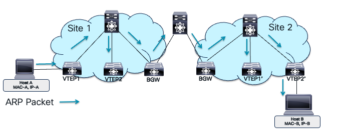
VXLAN Flooding Domain
In the image, Host A and Host B are on the same bridge domain extended across two VXLAN sites. Host A resolves Host B’s MAC address using ARP, sending a broadcast request across the site. The bridge domain extension increases the failure domain, flooding it and extending the failure domain. Adding more bridge domains multiplies the failure domains, while adding multicast and broadcast applications increases storm triggers in each domain. As a network architect, it’s crucial to understand the security implications of mobility and VXLAN domain extensions, including potential risks and prevention mechanisms.
VXLAN Virtual Network Identifiers (VNIs) represent virtualized networks in the overlay. The ethernet VLAN maps Layer 2 VNI. The IP VRF maps to Layer 3 VNI. Multiple Layer 2 VNIs (bridge domains) can exist in a single Layer 3 VNI providing integrated routing and bridging (IRB) over a single VXLAN tunnel.
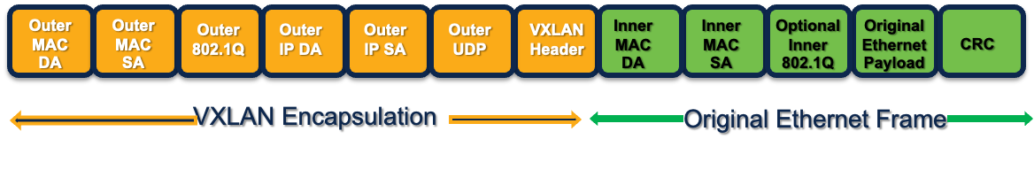
VXLAN Overlay Encapsulation
Network segmentation is crucial for modern layered defense strategies. It isolates different tenants or applications, groups them, and prevents unauthorized access using ACLs. In a flat network, attackers can easily move across systems if one is compromised. Segmentation barriers, such as network devices, route traffic between VLANs or VRFs, allowing security policies to prevent lateral movement. This reduces the attack surface, limiting the attacker to one network segment. Each segment can have unique access policies based on user and application requirements. Generally, segments with mission-critical or high-risk IT resources have strict security policies. Network segmentation is a basic compliance requirement for regulatory standards like PCI-DSS, HIPAA, and GDPR, ensuring audit readiness. The VXLAN VNI provides traffic isolation in the data plane by storing MAC addresses in isolated MAC-VRF tables and IP addresses in isolated IP-VRF tables. Traffic can only cross IP VRFs using administratively defined route leaking policies or routing through fusion edge routers or routed firewalls.
Another layer of network segmentation is micro-segmentation. The VLANs are part of VRFs. VLANs can further be divided into security group, providing isolation within a bridge domain.
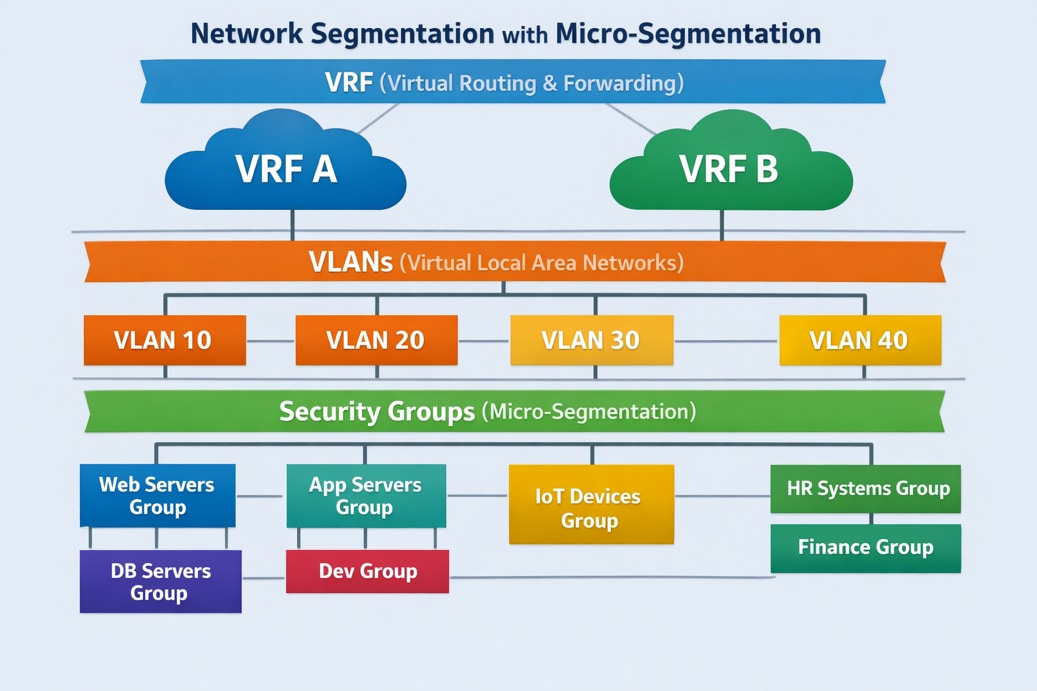
Network Micro-Segmentation Hierarchy.
Micro-segmentation is a network security technique that groups network resources into Security Groups (SGs) based on application attributes or other criteria within a VXLAN EVPN fabric. This allows for granular, application-centric security policies between groups using Security Group Access Control Lists (SGACLs), regardless of the network topology. Integrating Cisco TrustSec, micro-segmentation controls east-west traffic within the data center, improving security by limiting communication to authorized endpoints and enabling a zero-trust model. This method provides better control over traffic flows among application tiers and workloads, reducing the attack surface and enhancing compliance and auditing capabilities. To learn more about micro-segmentation in VXLAN BGP EVPN fabrics, refer to the white paper titled "Securing Data Centers with Microsegmentation using VXLAN GPO” on Cisco.com
The MP-BGP EVPN control plane protocol defines and distributes MAC and IP address distributions in each VNI. It uses the same MP-BGP VPN NLRI field route distinguisher (RD) and attribute route targets (RT) for distinguishing overlapping routes across customers or tenants. The RD configures MP-BGP to generate unique prefixes for each customer using different RD values. For example, customer A in VRF A will have an MP-BGP EVPN route of RD1:192.168.1.0/24, while customer B in VRF B will have an MP-BGP EVPN route of RD2:192.168.1.0/24. The RD in VXLAN BGP EVPN attaches to both MAC and IP routes to distinguish entries in the MAC-VRF for layer 2 VNI and IP-VRF for layer 3 VNI. The table below summarizes the RD format on Cisco Nexus 9000 NXOS for MP-BGP EVPN control plane.
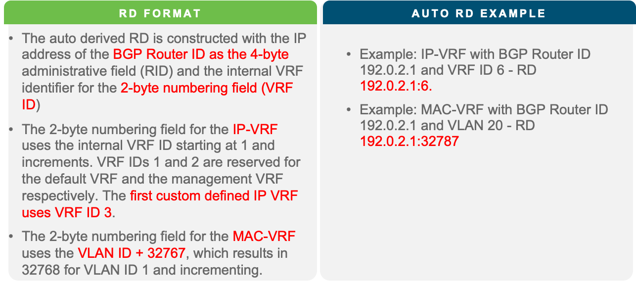
Nexus 9000 NX-OS EVPN RD
RT is an MP-BGP extended community attribute. The purpose of the RT is to control the import and export of routes between VRFs. The RT format on Cisco Nexus 9000 NXOS for MP-BGP EVPN control plane is explained in the table below.
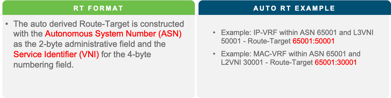
Nexus 9000 NX-OS EVPN RT
The MP-BGP EVPN control plane protocol uses RT information to support and exchange tenancy isolation across the fabric for all the VNIs configured on the leaf devices. The RT ensures the routes for each VNI are stored in their respective isolated forwarding tables. The MP-BGP EVPN configuration requires the definition of the IP and MAC VRF and then enabling the MP-BGP EVPN peering between the leaf and spine nodes in the fabric to exchange routes for each VNI.
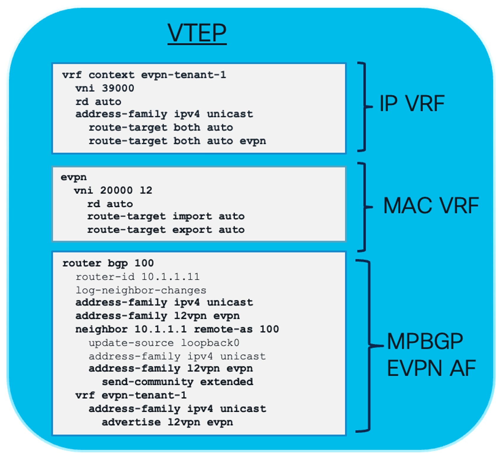
Nexus 9000 NX-OS MP-BGP EVPN Tenant Configuration
The data and control plane in VXLAN BGP EVPN fabric supports isolation of tenant traffic through network segmentation. The VXLAN BGP EVPN fabric network architecture has another layer of separation, which is the underlay and overlay network. One network domain exists in the default VRF, which is the underlay network, and the custom VRF network domain exists as part of the overlay network.
The underlay network is the physical layer three network that provides connectivity between the leaf devices or VXLAN Tunnel Endpoints (VTEP). The underlay network has unicast routing protocols such as OSPF, ISIS, or eBGP to provide VTEP to VTEP connectivity. The underlay network may also have a multicast routing protocol such as PIM to manage broadcast, unknown unicast, and multicast (BUM) traffic. The underlay carries the VXLAN encapsulated traffic from one VTEP to the other. The underlay network provides connectivity for MP-BGP EVPN neighbor relationships. Network failures in the underlay impact VXLAN encapsulated traffic, which will affect connectivity in the overlay.
The overlay network in a VXLAN BGP EVPN data center architecture is the virtual network built on top of the physical underlay. Its purpose is to provide logical Layer 2 (bridging) and Layer 3 (routing) connectivity across a routed IP fabric using a point-to-multipoint VXLAN tunnel. The overlay network domain runs its own isolated instance of routing protocols inside custom VRFs. The same routing protocols such as OSPF, ISIS, eBGP, and PIM are also run in the VRFs part of the overlay network domain. The OSPF and IS-IS routing protocols play a role in the hand-off to external networks. MP-BGP EVPN, as explained earlier, is part of the overlay control plane protocol because it signals tenant MAC and IP routing information between leaf and spine nodes. For multicast routing in the overlay, Nexus 9000 NX-OS uses MP-BGP NGMVPN to signal source and receiver information attached to the VTEP. The tenants, applications, and endpoints are part of the overlay network.
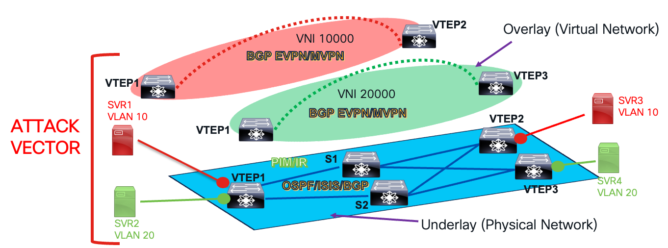
Underlay and Overlay Network Layers
Securing a VXLAN BGP EVPN data center network involves configuring, troubleshooting, and managing routing and switching protocols and forwarding tables in both the underlay and overlay networks. Compromising any layer affects tenant traffic and services, making both networks vulnerable. Understanding vulnerabilities in the data and control planes of both networks helps apply mitigations to protect the VXLAN network from attacks and prevent incidents. Control plane and data plane protection mechanisms for the underlay and overlay networks are explained in the following sections.
First Hop Security in VXLAN Fabrics
Leaf layer security is enforced on the VTEPs attached to the workload, also known as access security since the host or endpoint is on the access side. It isolates VRFs, inter-VLAN policies, and micro-segmentation directly at the workload’s first hop, enabling scalable, line-rate, zero-trust security for east-west and north-south traffic without centralized bottlenecks.
On the Cisco Nexus 9000 NX-OS, various mechanisms provide leaf layer security against host attacks. These include Port Security and endpoint security mechanisms like DHCP Snooping, Dynamic ARP Inspection, and IP Source Guard.
Access Port Security
Port security is a network security feature that restricts access to switch ports by limiting the hosts that can connect. This prevents unauthorized access and protects the network from malicious attacks by limiting the MAC addresses that can be learned or used on a specific port.
A malicious host can send multiple flows with different Source MAC addresses, forcing the switch to learn these addresses. This exhausts the switch’s MAC table, making legitimate MAC learning impossible. As a result, good hosts experience Unknown Unicast traffic. The switch’s MAC address table is a finite resource, and filling it with bogus entries is clearly not intended. Port Security helps prevent these attacks.
This feature works in its simplest form by enforcing a maximum number of MAC addresses on a specific port using the following interface-level command:
switchport port-security maximum <max-number-of-macs>
Once the port’s limit is reached, the default action is to shut it down. However, other violation actions can be configured. These options can be set using the following interface-level command:
switchport port-security violation { protect | restrict | shutdown }
The violation actions are as follows:
● Default action is shutdown- which means the port will be shut upon port-security violation.
● If restrict action is configured, after the first violation, any later traffic that requires new MAC learning, is dropped. The violation is logged.
● If the protect action is configured, it functions similarly to the restrict action, but it does not log violations. Cisco port-security protect is used instead of restrict when you want silent enforcement of MAC limits without generating logs, alerts, or operational noise. This is particularly useful in environments with normal MAC churn and where violations are not considered actionable security events.
MACs learnt on a port configured with port security are shown as “secure” MACs in hardware. The show hardware mac-address table command output is displayed as follows:
101 0012.0100.0001 secure - T F Eth1/48
In a VXLAN environment, secure MACs on a remote VTEP are shown as “static”. Secure MACs are tied to a particular port and no MAC-move is supported for secure MACs. Hence, remote VTEPs display the secure MACs as “static” as shown below output.
N9K-Leaf-1# show hardware mac-address table
Legend:
* - primary entry, G - Gateway MAC, (R) Routed MAC
VLAN MAC Address Type Age Secure Ports
---- ----------- ---- --- ------ -----
10 0050.56bf.12a3 dynamic 0 Yes Eth1/10
20 001c.73aa.9f10 dynamic 120 No Eth1/12
30 0050.56bf.34b7 static - Yes Eth1/15
DHCP Snooping
DHCP snooping, a well-known security feature in non-VXLAN topologies, is explored in this white paper within the context of a VXLAN environment.
In data center networking, DHCP-based IP assignments are crucial. They provide a dynamic and automated way to assign IP addresses and configuration parameters to hosts, significantly reducing manual configuration errors and administrative tasks. This is especially important for data centers, where dynamic provisioning of servers and virtual machines, along with support for mobility and workload migration, is essential.
DHCP Snooping enhances network security by ensuring that a host’s IP address is assigned by a legitimate DHCP server. This prevents rogue servers from assigning compromised IPs, a common attack vector. As a primary use case, DHCP Snooping provides security hooks to thwart such threats. Additionally, it lays the groundwork for other security features like Dynamic ARP Inspection (DAI) and IP Source Guard (IPSG).
This section provides a refresher on the DHCP protocol handshake between a host/endpoint and a DHCP server. The handshake is summarized in the accompanying diagram.
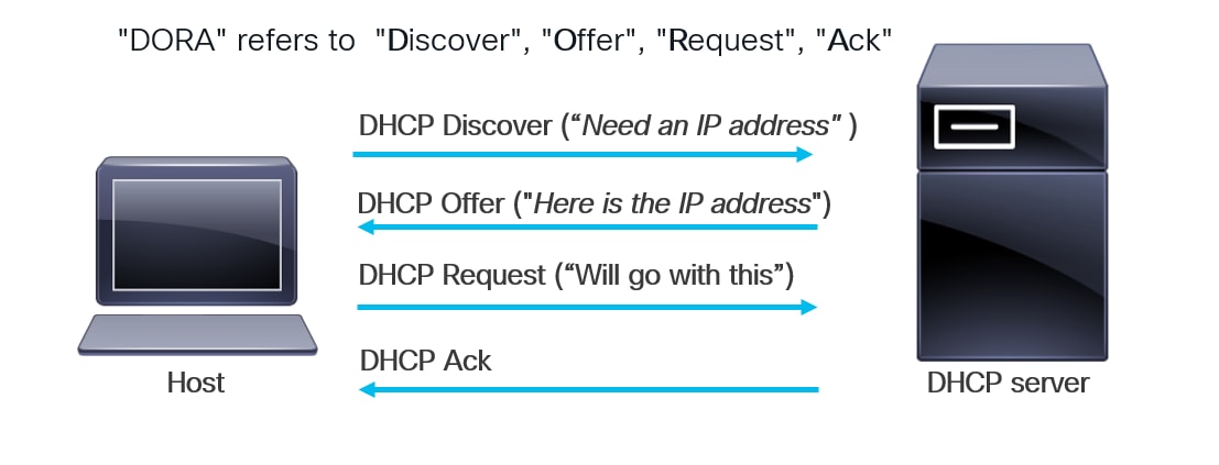
DHCP Handshake between a Host/Endpoint and DHCP Server
● A host connected to a network needs an IP address. It sends a DHCP Discover message to the DHCP server, usually as an L2 broadcast. Switches in the network forward this message within the L2 broadcast domain. The DHCP server receives it. If the server is not on the same L2 domain, we can use secured DHCP relay servers with AES encryption to protect all passwords on the relay device.
● The server then responds with a DHCP Offer, providing the host with the assigned IP address.
● The host receives this offer and initiates a DHCP Request to register with the server.
● The server responds with a DHCP Acknowledgement, completing the DHCP handshake.
The sequence of DHCP messages—Discover, Offer, Request, and Acknowledge—is commonly referred to as “DORA.” Once the DORA message handshake concludes, the host receives an IP address. However, this exchange can be exploited by a malicious server within the network. This security issue is detailed in the next section.
Security Loophole in DHCP Handshake
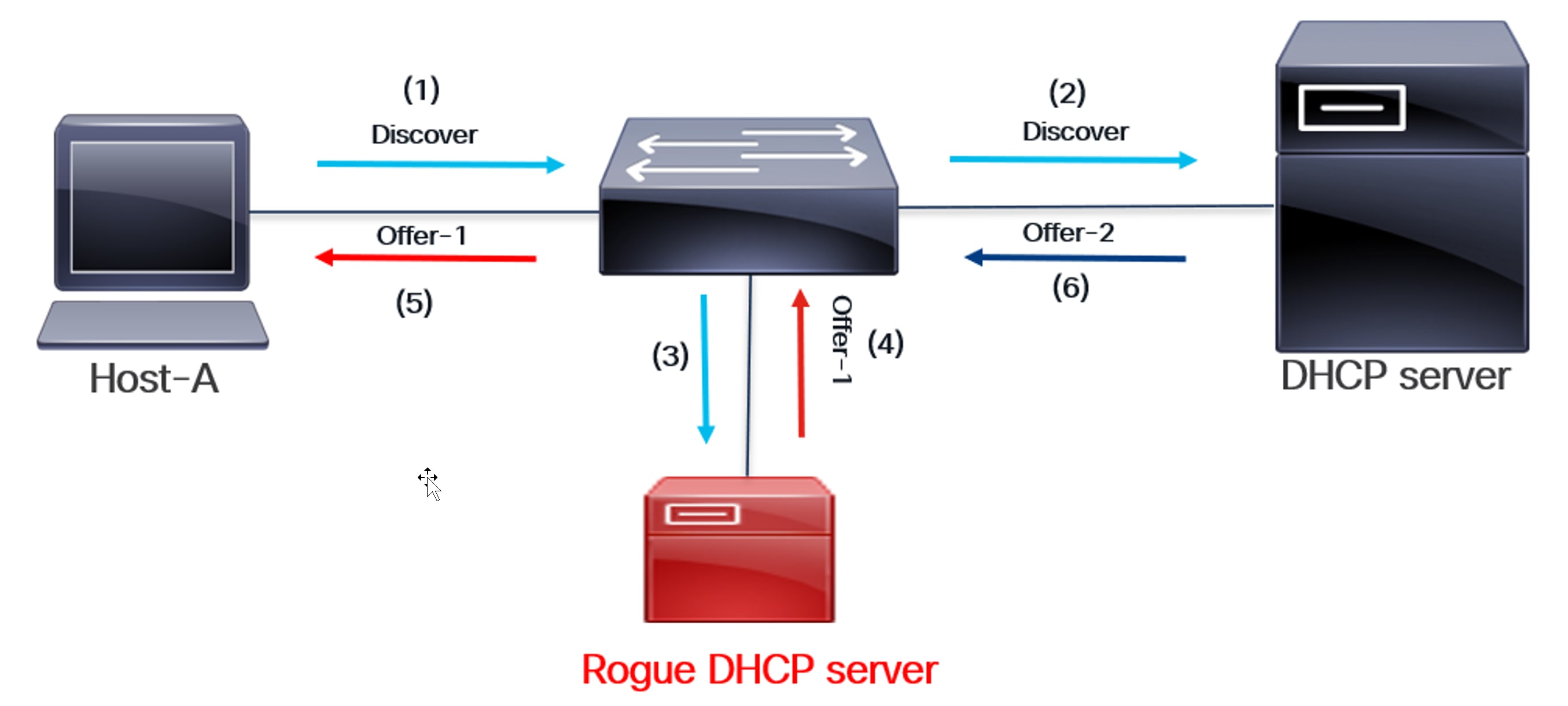
Rogue DHCP Server Intercepts Discover and Responds
The above diagram illustrates the security loophole in a DHCP handshake. A rogue DHCP server can intercept a DHCP handshake as shown:
(1) Host A sends a DHCP Discover message to a DHCP server in the network, requesting an IP address.
(2) DHCP Discover is a broadcast message. The switch sends it to all interfaces within the host’s local area network (LAN) broadcast domain (VLAN). This message is then sent to the appropriate DHCP server.
(3) Since the interface is in the same Layer 2 broadcast domain, DHCP Discover is also sent to the rogue DHCP server.
(4) The rogue DHCP server responds with an Offer before the legitimate one does.
(5) The Offer from the Rogue server reaches the host.
(6) The legitimate DHCP server sends an offer, but it arrives too late. The host has already completed transactions with the rogue server.
(7) At the end of this transaction, the host’s IP address is compromised because it was assigned by a rogue DHCP server. The rogue server also sends its DHCP Server Gateway IP address in the Offer message. As a result, routed packets from the host will now reach the rogue server. This can cause significant network problems by assigning incorrect or conflicting IP addresses to clients, potentially leading to connectivity issues or unrouteable IP addresses. Furthermore, rogue DHCP servers may provide malicious DNS server information, redirecting users to fake websites to steal credentials or sensitive data.
DHCP Snooping as a solution
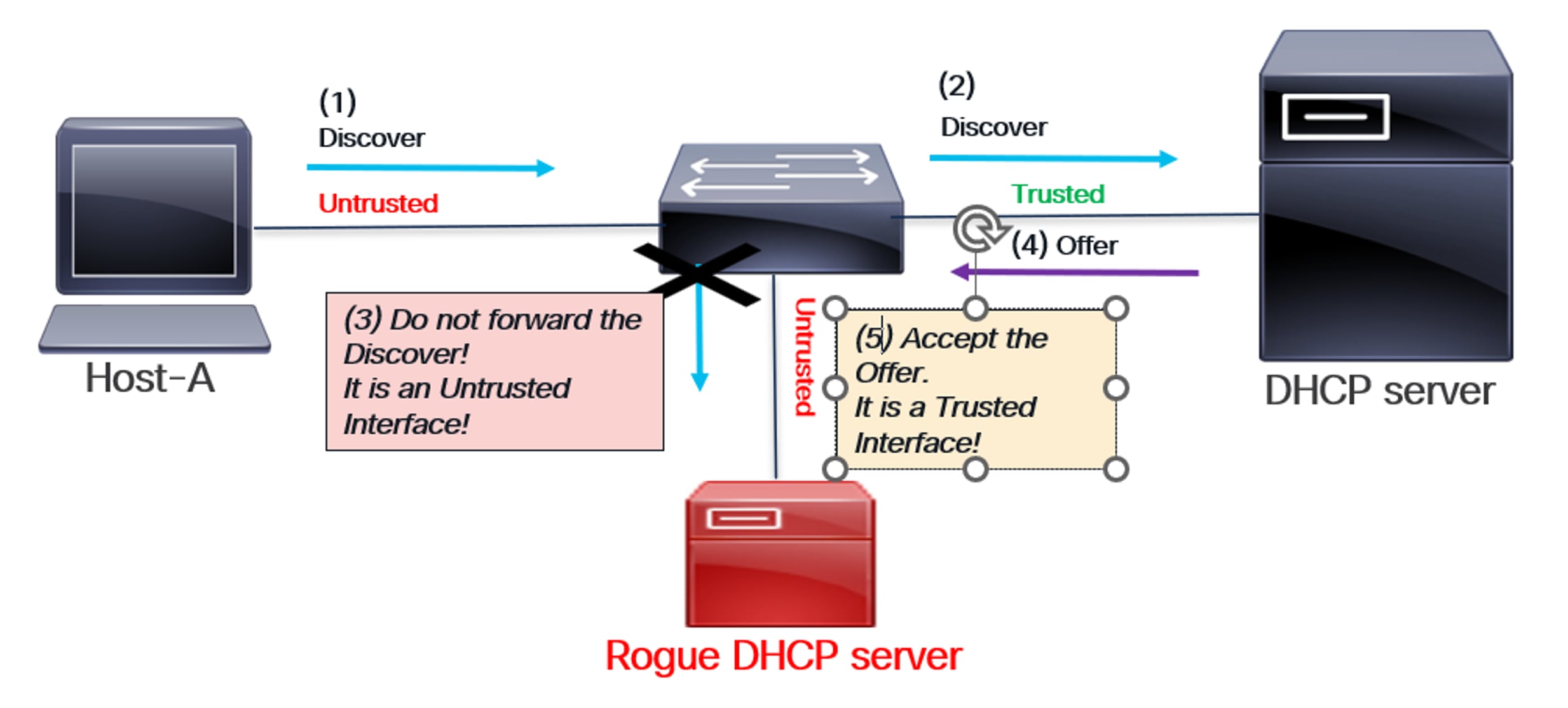
● To address this security issue, the DHCP Snooping feature is enabled on the network switches. This feature configures the interface facing the DHCP server as a “Trusted” interface, while all other interfaces on the switch are defaulted to “Untrusted.” When DHCP servers run in virtual machines, it’s common to configure the ports connected to the host VMs as trusted interfaces. This is necessary because DHCP snooping drops messages received on untrusted ports. However, this also means the trusted boundary extends to all those host ports.
● Once DHCP snooping is enabled, the switch snoops or monitors DORA messages before forwarding them. This is typically done by redirecting the traffic to the switch’s CPU, a process known as “packet punt.”
● With the DHCP Snooping feature enabled, the switch will now forward DHCP Discover messages only to trusted interfaces. This prevents malicious DHCP servers from receiving a DHCP Discover, eliminating the risk of them responding with a malicious Offer message. This is the fundamental mitigation technique behind DHCP Snooping.
● Once the DHCP Discover reaches the DHCP server, it responds with an Offer message that contains the IP address of the host. The switch connected to the DHCP server has DHCP Snooping feature enabled. It snoops the Offer message and forwards the Offer message to the host only if the Offer was received from a Trusted interface. This ensures that the Offer message that contains the IP address is received from a Trusted interface, which denotes the presence of a valid and secure DHCP server.
● As previously mentioned, the DHCP Offer message is followed by the DHCP Request and DHCP Acknowledgement.
DHCP Snooping helps confirm that the DHCP handshake occurs between the host/endpoint and a legitimate, trusted DHCP server. This is illustrated in the accompanying diagrams.
How DHCP Snooping provides endpoint security
As shown in the above diagram:
The switch’s DHCP Snooping feature is enabled. The interface connected to the legitimate DHCP server is configured as Trusted, while all other interfaces, including the one connected to the rogue server, are implicitly Untrusted.
(1) A host sends a DHCP Discover message to a DHCP server in the network to obtain an IP address.
(2) The switch snoops on DHCP Discover packets. Since it’s a trusted interface, the switch forwards them to the legitimate DHCP server.
(3) DHCP Discover is not sent to the rogue DHCP server because it’s an untrusted interface.
(4) The DHCP server sends an offer to the switch.
(5) The switch monitors the Offer message, confirming it originates from a Trusted interface. This validated Offer is then forwarded to the host. The DHCP handshake concludes with the Request and Acknowledgement.
Therefore, the rogue DHCP server cannot respond with a malicious offer in this scenario. This guarantees that the host’s assigned IP address remains secure.
DHCP Snooping Database
Once the DORA exchange is complete, a DHCP Snooping Database entry is created on the switch directly connected to the host.
● This database contains the MAC address of the host or endpoint, the IP address assigned by the DHCP server, and other details like lease time.
● The DHCP Snooping database serves as the foundation for other security features, such as Dynamic ARP Inspection (DAI) and IP Source Guard (IPSG), which we will explore later.
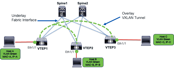
DHCP Snooping in VXLAN
In the previous sections, we discussed the DHCP handshake, a potential security loophole, and DHCP Snooping as a security solution. This section explores DHCP Snooping in the context of VXLAN topology. In a VXLAN network, a host connects to a VTEP (also known as a Leaf). The DHCP server can connect to the same VTEP or another one within the same fabric. In some cases, it can even connect to a VTEP in a different site, creating a multi-site VXLAN topology.
As previously explained, the DORA exchange must now operate across the VXLAN fabric. All VTEPs (leaf nodes) in the VXLAN fabric have DHCP Snooping enabled. Similarly, the interface connecting each VTEP to the DHCP server is configured as a “Trusted” interface within VXLAN. Once DHCP Snooping is enabled, DORA messages are “snooped” (meaning they are sent to the CPU) and then forwarded to specific interfaces after thorough security checks.
In VXLAN, the fabric interface—the uplink to the spine—is implicitly trusted. This is necessary for DORA messages to travel across the VXLAN fabric between a host on one VTEP and a DHCP server on another.
The DORA exchange in VXLAN with DHCP Snooping enabled is shown in the following diagram:
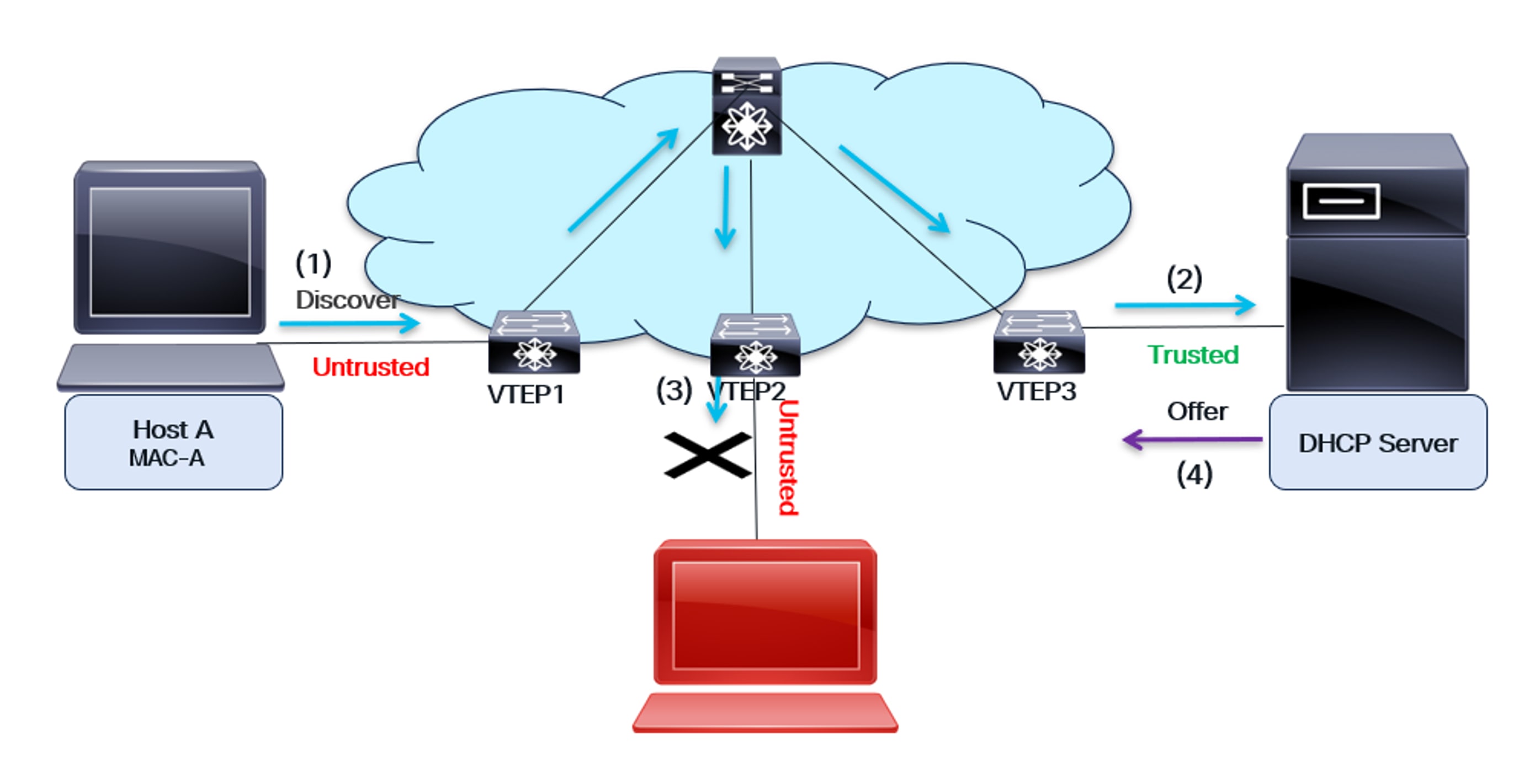
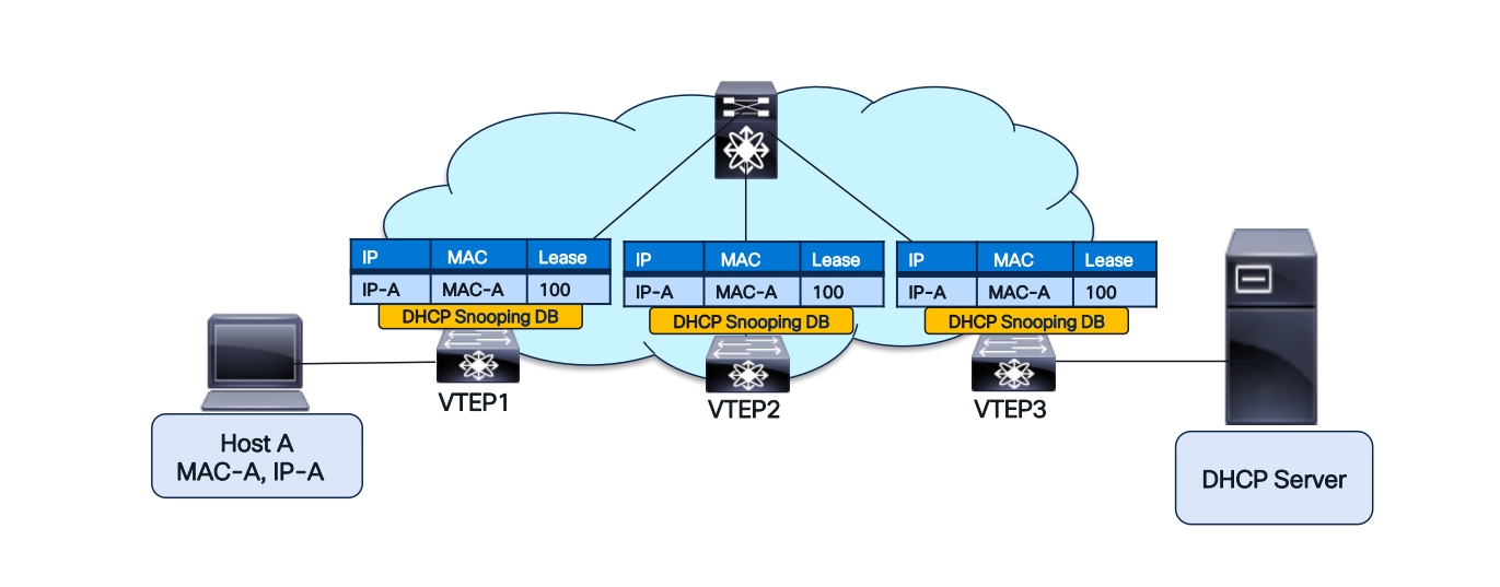
DHCP Snooping in VXLAN
As shown in the diagram:
● The host and the DHCP server are on different switches. Host A is connected to VTEP1, while the DHCP server is connected to VTEP3. These two devices can be on the same fabric (as illustrated in the diagram), or they can be on different fabrics (for a multi-site use case).
● All the Leaf switches—VTEP1, VTEP2, and VTEP3—are configured to snoop on DHCP.
● The interface facing the DHCP server is configured as Trusted, while all other interfaces on the VTEPs are implicitly untrusted.
● The uplink interface, which connects the VTEP to the Spine switch, is implicitly trusted.
(1) The host sends a DHCP Discover message to obtain its IP address from the DHCP server. VTEP1, connected to the host, receives the message and forwards it to the CPU. If the interface is “Trusted,” the DHCP Discover message is broadcast on all L2 interfaces for that VLAN. VTEP2 and VTEP3 receive the Discover message.
(2) VTEP3 receives the Discover message and snoops it. Since it’s a trusted interface, the message is forwarded to the DHCP server.
(3) VTEP2 receives the Discover message and inspects it. Since it’s an untrusted interface, it does not forward the message to the rogue DHCP server.
(4) The server responds with a DHCP Offer message containing the host’s IP address. VTEP3 checks if this message originates from a trusted interface. If not, it discards it. The DHCP Offer is then sent back to the host over the VXLAN fabric.
Creation of the DHCP Snooping Database entry on VTEP1
The host completes the DORA handshake with the server, resulting in the assignment of a secure IP address. Following this, a DHCP Snooping Database entry is created on the VTEP adjacent to the host, specifically VTEP1. This entry contains the host’s MAC address, the DHCP server’s assigned IP address, and other details like the lease time.
Note: It is possible to statically add DHCP snooping entries into the DHCP snooping database using the command below:
ip source binding ip address vlan vlan-id interface interface
Static entries are distributed across all VTEPs. DHCP Snooping serves as the foundation for security features such as Dynamic ARP Inspection (DAI) and IP Source Guard (IPSG). Dynamic ARP Inspection is discussed in the next section.
Dynamic ARP Inspection
Dynamic ARP Inspection (DAI) is a security feature on switches that prevents ARP spoofing and poisoning attacks in a network.
ARP spoofing security issue
The diagram shows a typical ARP spoofing security issue in the network.
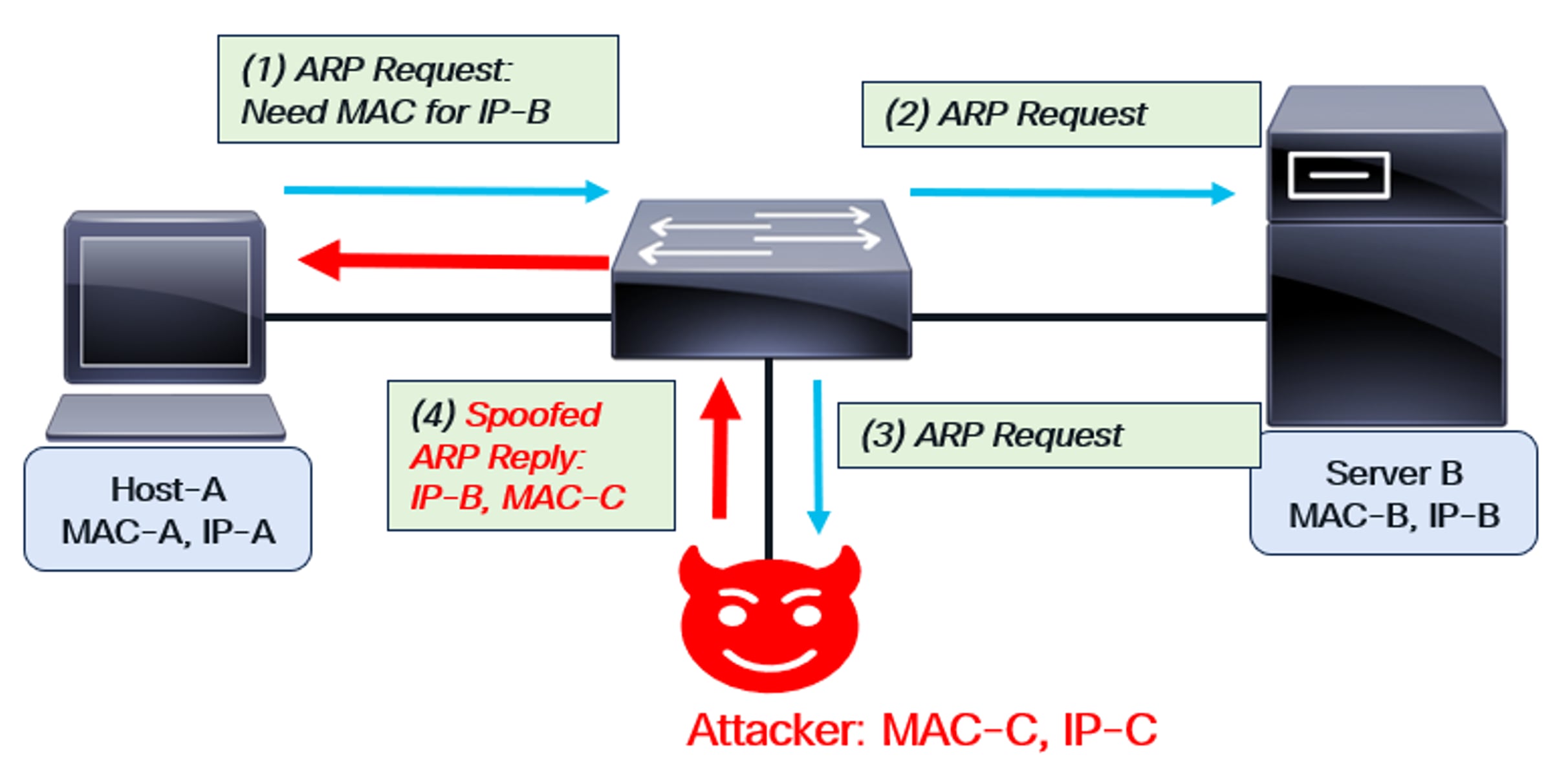
ARP Spoofing
As depicted in the figure, Host-A sends an ARP request to obtain Server-B’s MAC address. An attacker intercepts the request and responds, spoofing as Server-B. Using their own MAC address (MAC-C) and Server-B’s IP address (IP-B), the attacker sends an ARP reply back to Host-A. This compromise allows the attacker to intercept any packets sent between Host-A and Server-B. The attacker’s MAC address is embedded in the packets, which are then forwarded to the attacker. This is known as a “man-in-the-middle” or ARP spoofing attack.
Using Dynamic ARP Inspection to solve the attack
Dynamic Address Assignment (DAI) is enabled for a specific VLAN on the switch. As mentioned earlier, DAI requires DHCP Snooping to be pre-enabled. With snooping enabled, the switch populates its DHCP Snooping Database with the MAC-IP addresses of all valid hosts. These valid hosts have successfully completed a DORA handshake.
Once DAI is enabled, ARP requests and replies are monitored. The MAC address and IP address of the source in the request or reply are compared to entries in the switch’s DHCP Snooping Database. If there is no match, the request or reply is dropped. Since the rogue host’s spoofed MAC-IP combination won’t match any entry in the database, the malicious ARP requests and replies are also dropped.
This Dynamic ARP Inspection behavior is shown in the diagram below:
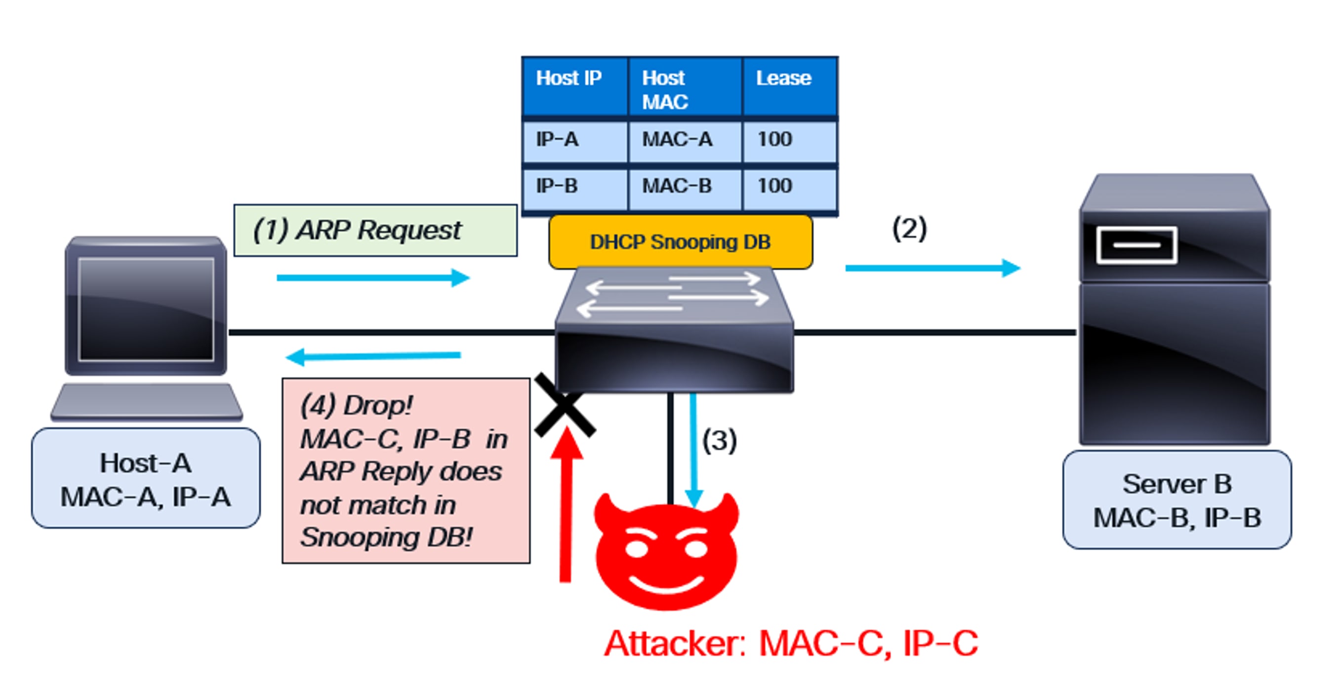
DAI functionality
As shown in the diagram:
● The switch has DHCP snooping enabled, and DAI is configured on the VLAN for Host-A and Server-B.
● The DHCP Snooping Database is created on the switch based on the previous DORA handshake.
● This database contains the MAC-IP combination of Host-A and Server B.
(1) Host-A sends an ARP request to obtain Server-B’s MAC address (IP-B). Since DAI is enabled on the switch for this VLAN, it snoops the request. The host’s credentials (IP-A, MAC-A) match the DHCP Snooping Database, so the switch forwards the ARP request.
(2) The ARP request is sent to Server B.
(3) Since an ARP request is a broadcast, it’s also forwarded to the attacker.
(4) The attacker sends spoofed packet—IP-B and MAC-C—in the ARP Reply. This reply reaches the switch, which then snoops it. Since there is no matching entry in the DHCP Snooping Database, the spurious reply is dropped.
Thus, DAI works to solve the security issue caused by ARP spoofing.
DAI in VXLAN
In VXLAN, Dynamic ARP Inspection (DAI) operates similarly to its non-VXLAN counterpart. DAI is enabled on every Leaf VTEP within the fabric. Host ARP requests and replies are forwarded to the CPU for verification of the Source MAC address and Source IP, using entries from the DHCP Snooping Database.
The diagram below illustrates this VXLAN behavior. The rogue server sends a MAC-IP combination in its ARP reply that is absent from the DHCP Snooping Database. This erroneous message is discarded.
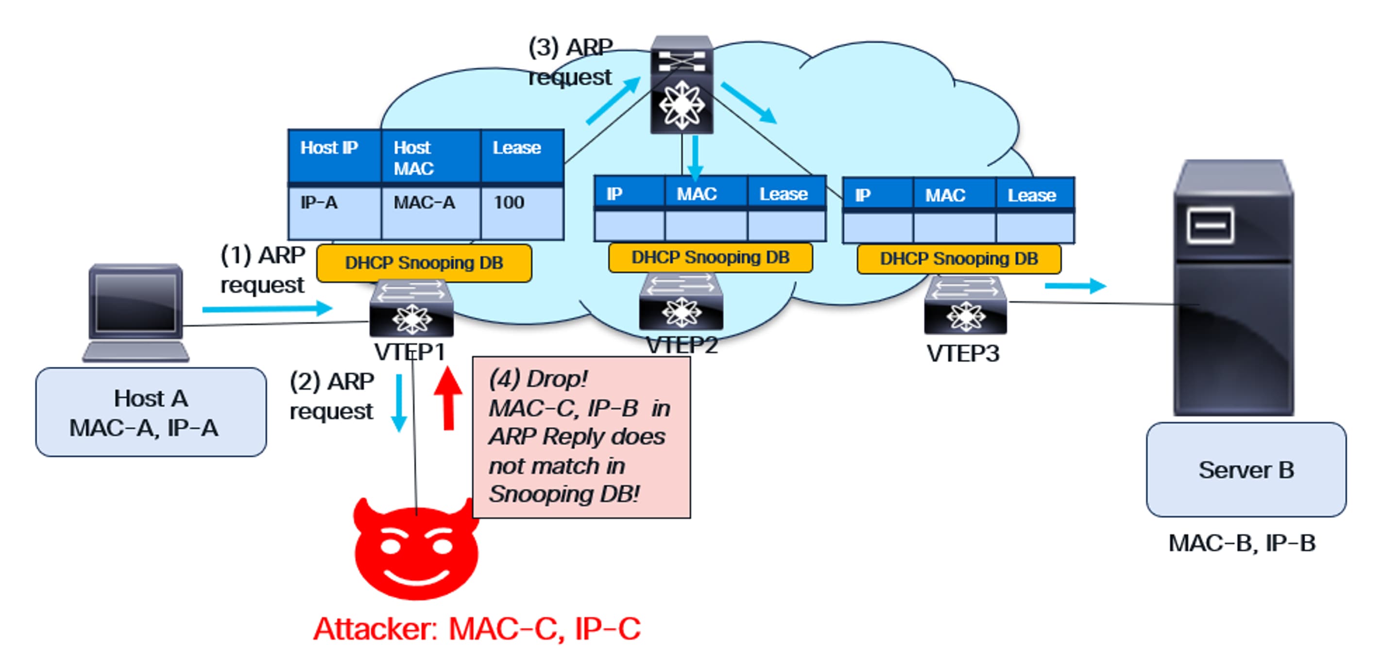
DAI functionality in VXLAN
IP Source Guard
Another important endpoint security feature is IP Source Guard (IPSG). While DAI validates control-plane messages like ARP for correctness, IPSG secures the data plane. It validates data packets to ensure the source MAC-IP combination is valid on the switch.
The diagram below illustrates the problem caused by data-plane spoofing.
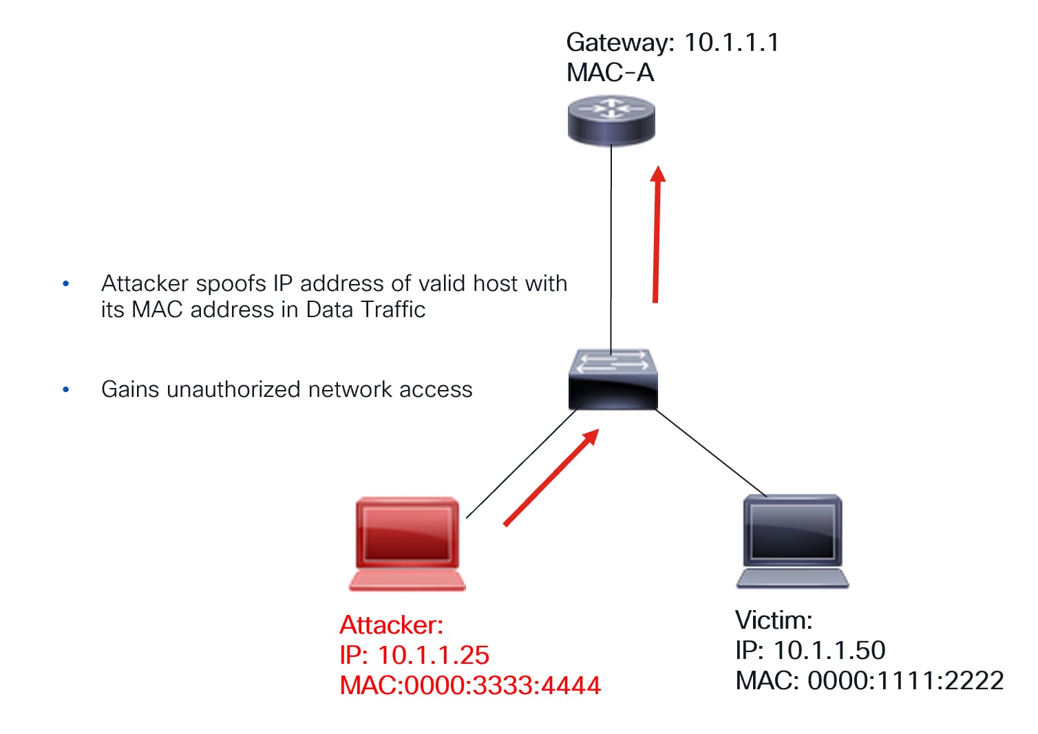
Data path spoofing
As shown in the diagram, a malicious host uses its MAC address but spoofs the IP address of a legitimate host within a data packet. This compromises the network because traffic intended for the legitimate host is now redirected to the attacker. Consequently, remote hosts will use the attacker’s MAC address instead of the valid hosts.
How IPSG solves this problem:
● The switch has DHCP snooping enabled, and IPSG is configured on the interfaces corresponding to the hosts.
● The DHCP Snooping Database is created on the switch based on the previous DORA handshake.
● This database contains the MAC-IP combination of valid hosts. It’s downloaded to hardware when IPSG is enabled.
● If a host sends a packet with an invalid MAC-IP combination, the packet is dropped.
Thus, the data-plane is protected.
IPSG functionality is shown in the following diagram.
How IPSG protects the data-plane
IP Source Guard in VXLAN
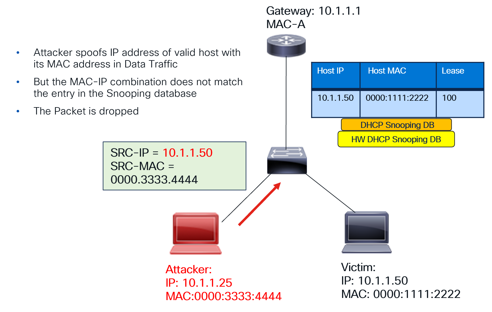
The IP Source Guard (IPSG) feature is enabled on a per-interface basis for every VTEP. When enabled, the DHCP Snooping Database, previously created as part of DORA, is downloaded to the hardware. Any data packet from the endpoint or host is then verified for correctness against this downloaded database. Specifically, the packet’s Source MAC and Source IP combination must be present in the downloaded database.
This validation protects the data plane. With IPSG, traffic from an attacker attempting to spoof an address in the data plane is blocked. The attacker’s MAC-IP combination won’t match the DCHP Snooping Database entry on the hardware.
The IPSG functionality in VXLAN is illustrated below:

IPSG functionality in VXLAN
VXLAN and DHCP Snooping Database
The VXLAN fabric has unique characteristics, including the ability for hosts and endpoints to dynamically move within it. This is a key advantage of VXLAN. However, this dynamic movement presents challenges to the functionality of endpoint security features.
Let’s consider a host that has secured its IP address through the DORA exchange. The DCHP Snooping Database contains an entry for this host only on the VTEP connected to it (the Source VTEP). This entry is absent on other VTEPs within the fabric.
Since the host move is possible, what happens when the host moves to a new VTEP in the fabric? If the host sends an ARP after the move, the new VTEP’s database won’t have an entry for it. Similarly, IPSG will face the same issue on the new VTEP.
For this reason, the DHCP Snooping table database in VXLAN needs enhancement. After a DORA exchange, the DHCP Snooping database is populated with the MAC-IP combination of the host connected to the VTEP. BGP-EVPN is enhanced with a new Route Type (BGP EVPN RT-12), signaling the Snooping database entry to the entire VXLAN fabric. Consequently, all VTEPs in the fabric now have the same DHCP Snooping entry.
Once BGP EVPN RT-12 has distributed the DHCP Snooping table entry, host movement is seamless. When a host moves to a new VTEP and sends an ARP, it’s successfully matched on the new VTEP’s Snooping Database. IPSG also functions correctly on the new VTEP. This distributed DHCP Database enhancement provides security throughout the entire VXLAN fabric.
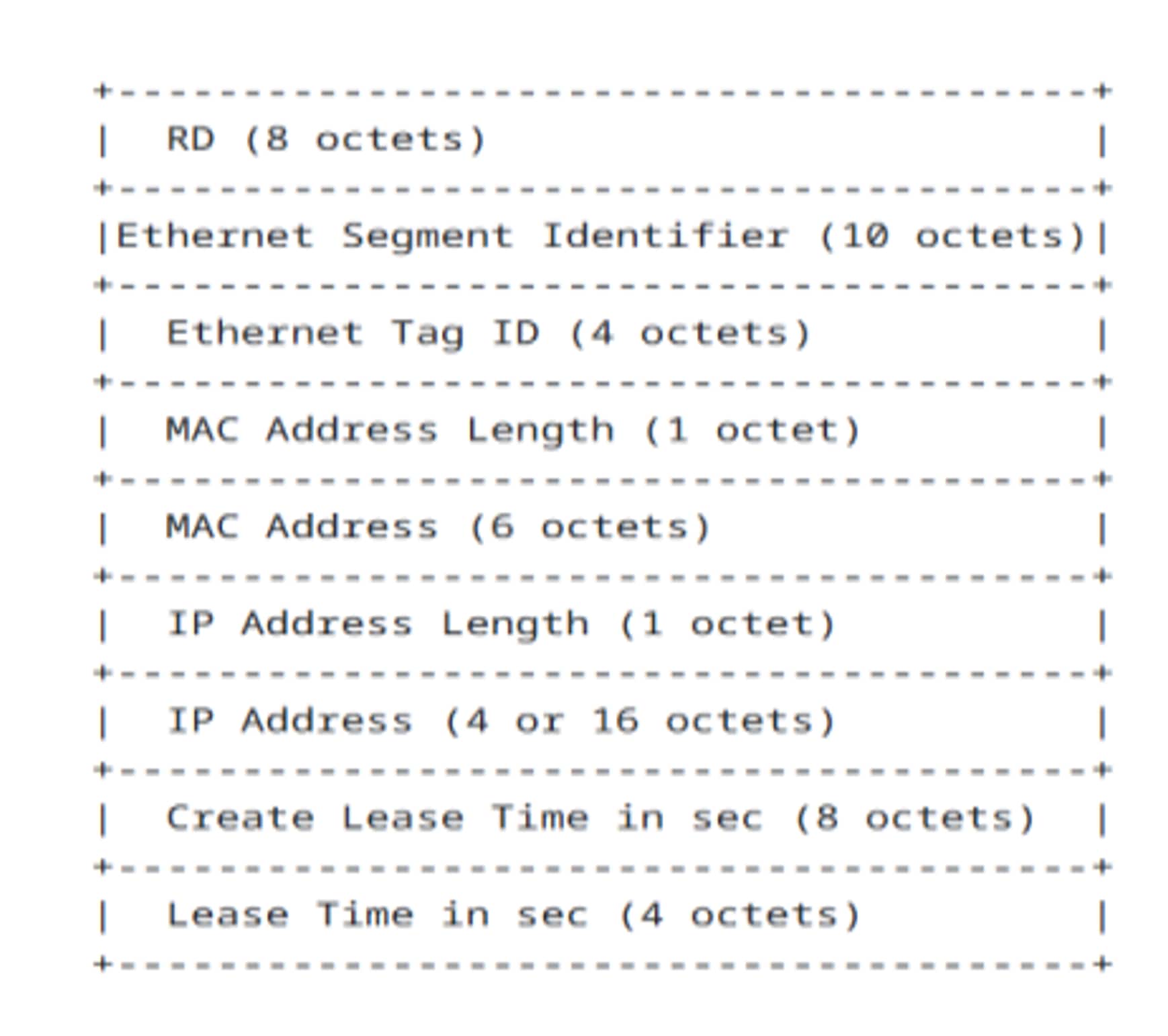
BGP-EVPN Route-Type 12 Fields
As depicted in the diagram above, BGP-EVPN Route-Type 12 (RT-12) includes the following information: Host MAC address, Host IP address, Create Lease Time, and Lease Time duration. This data is transmitted to the VXLAN fabric, ensuring that the DHCP Snooping Database is replicated across the entire VXLAN fabric, on each Leaf VTEP.
This enhancement allows endpoint security to be maintained in a VXLAN fabric, even when hosts and endpoints move.
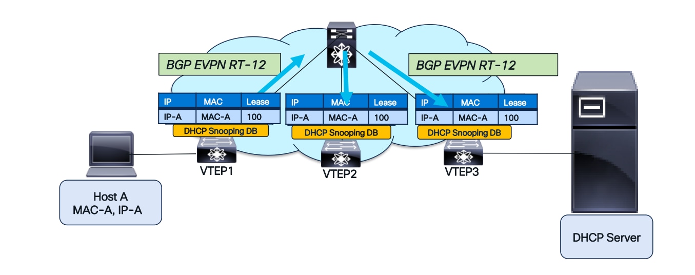
BGP-EVPN RT-12 to replicate the Snooping Database
The figure above illustrates RT-12’s operation. Following the DORA handshake between Host A and the DHCP server, VTEP1 acquires the DHCP Snooping entry for Host A. Initially, this entry is absent from the DHCP Snooping Database on VTEP2 and VTEP3. BGP-EVPN RT-12 will then transmit this information, subsequently populating the Snooping Database on VTEP2 and VTEP3.
DAI after host move
With the DHCP Snooping Database replicated across the fabric, DAI will successfully complete after a host move, as illustrated in the diagrams below.
DHCP Snooping Database replicated across the fabric
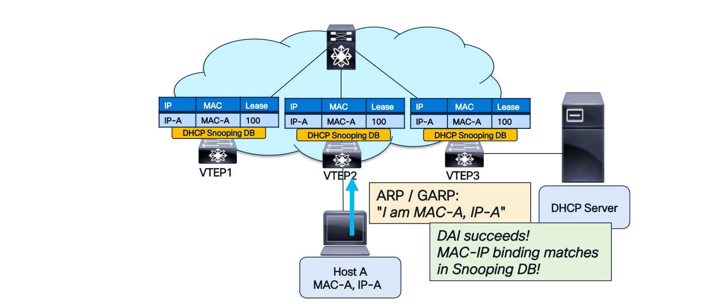
DAI after a host move
IPSG after host-move
IPSG will also succeed after a host move, as illustrated in the diagrams below.
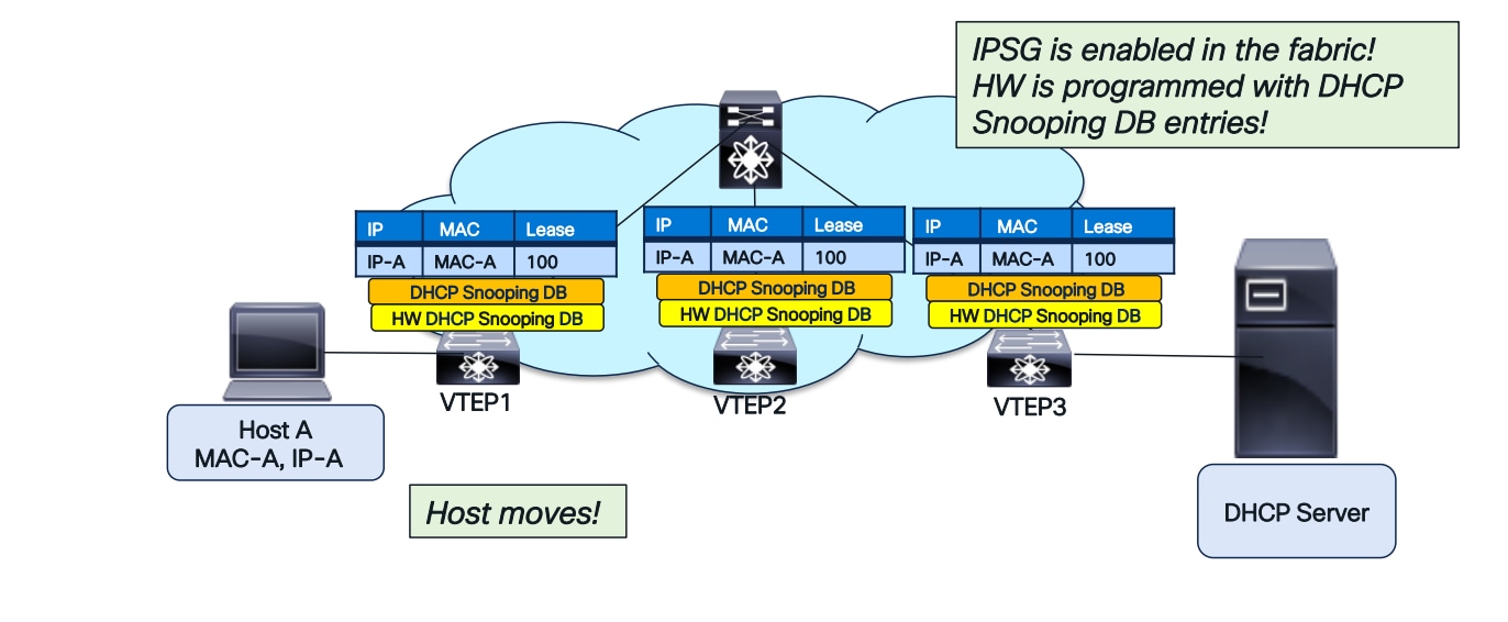
DHCP Snooping database downloaded to HW in the entire fabric for IPSG
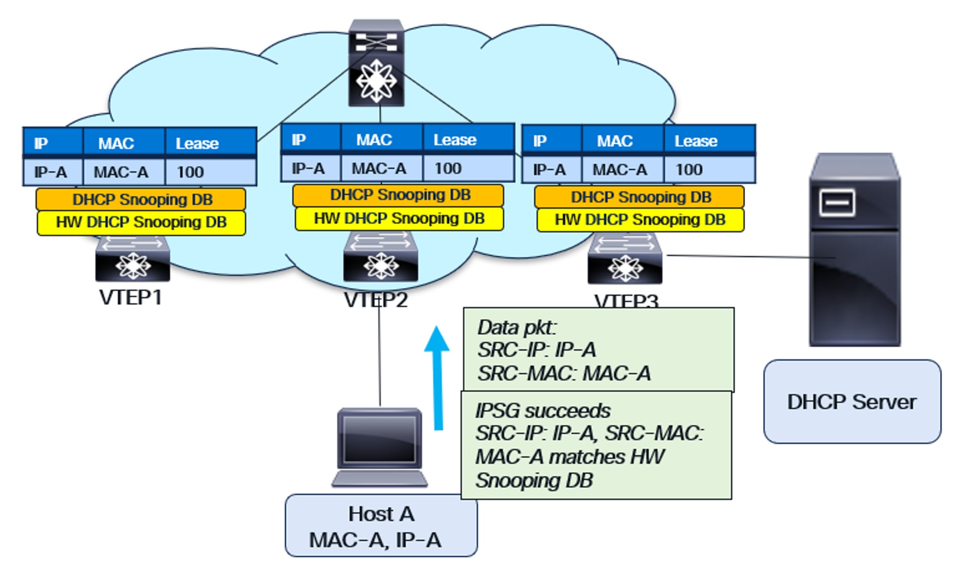
IPSG functionality with host move
Lease Time in DHCP Snooping Database
The “Lease Time” field in the DHCP Snooping Database is crucial. It specifies the duration for which a DHCP Server allocates an IP address to a host or endpoint. If the host needs to extend its IP address usage, it must send a DHCP Renew request to the server before the lease expires. If a host fails to renew its lease, and the lease expires on the DHCP server, the server is free to assign that IP address to another host or endpoint.
The Lease Time field is present in the DHCP Snooping Database on each Virtual Tunnel Endpoint Protocol (VTEP). It’s crucial to purge the DHCP Snooping entry after the Lease Time expires. Otherwise, conflicts can arise in the Snooping Database because the IP address will be reassigned to another host or endpoint, potentially with a different MAC address.
Each VTEP maintains a timer for the Lease Time duration of each Snooping Database entry. When the timer expires, the entry is removed from the Snooping database.
Maintaining an accurate Lease Time across the entire VXLAN fabric is crucial. If a database entry remains on some VTEPs while being purged from others, it creates inconsistency. This becomes particularly important when a new or reloaded VTEP is added to the fabric.
New VTEP Addition and Lease Time
When a new Virtual Tunnel Endpoint Protocol (VTEP) is added to the fabric, BGP EVPN RT-12 is learned and populates the DHCP Snooping Database entries in that VTEP. However, the lease time for this new VTEP should not be the full Lease Time duration, as the older VTEPs have already consumed some of it. Therefore, the DHCP Snooping Database for the new VTEP should be assigned the “Remaining Lease Time” instead of the total duration.
For this purpose, BGP EVPN RT-12 includes a “Create Lease Time” field. Using this field and the current time, the elapsed lease time is calculated. The remaining lease time is then assigned to the Snooping Database entry on the new VTEP. Therefore, implementing NTP is necessary to synchronize all switches’ clocks to a common time reference.
Data Plane Security in VXLAN Fabrics
The data plane forwards packets by switching traffic between sources and destinations. Data plane security encompasses the technologies, policies, and mechanisms employed to safeguard data traffic traversing the network.
Common data plane threats in a network include:
MAC/IP Spoofing: Forging a MAC or IP address to bypass security, impersonate a legitimate device, gain network access, connect to a service, or intercept traffic.
ARP Poisoning: Intercepting ARP requests and sending spoofed replies redirects traffic.
Flooding Attacks: A denial-of-service (DoS) attack that floods a network with high-speed DHCP, ARP, BUM, or random MAC address frames, causing traffic to drop.
Traffic Sniffing: Eavesdropping on traffic transiting through the network.
Data plane security attacks often originate from malicious actors, such as disgruntled employees within a company, compromised endpoints, or misconfigured systems lacking basic security best practices. This section explains the data center network engineer’s role in implementing data plane protection mechanisms to harden the VXLAN, BGP, and EVPN network infrastructure.
MAC/IP Moves
The MAC move occurs when a MAC address learned via EVPN Type 2 route from one VTEP is later advertised from another. The MP-BGP EVPN protocol uses a BGP extended community defined in RFC 7432 called the MAC Mobility Extended Community to track these moves. This community includes a 4-byte sequence number that increments with each host move. The example below illustrates the MAC mobility sequence number.
VTEP-1 detects Host 1 and advertises H-MAC-1 with sequence number 0.
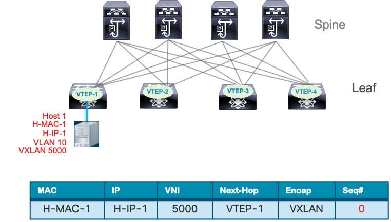
Host 1 Endpoint Learning
Host 1 moves from VTEP-1 to VTEP-3. VTEP-3 detects Host 1 and sends MP-BGP EVPN Type 2 route updates to Host 1, including itself as the next hop. It also increases the sequence number from 0 to 1.
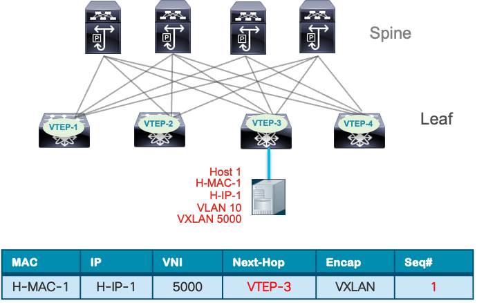
Host 1 Endpoint move
All other VTEPs receive the MP-BGP EVPN route update and compare the sequence number with the existing routing entry for the same MAC address. The BGP update with the higher sequence number takes precedence, while the earlier entry with the lower sequence number is removed from the BGP table. This feature of MAC move tracking prevents MAC flapping loops, facilitates rapid convergence after a VM mobility event, and can be combined with MAC move dampening to reduce frequent changes in endpoint location.
An IP move occurs when an IP address bound to a MAC address is advertised by a different Virtual Terminal Equipment Protocol (VTEP) than the one initially learned. This can happen due to mobility events or IP address conflicts caused by security incidents or misconfigurations. VM mobility events are expected operational occurrences. For example, in a high availability setup, a server in an active/standby configuration that performs a link failover to the standby path will cause the MAC/IP to be learned from the VTEP attached to the standby NIC.
The scenarios where IP address changes can lead to network incidents include:
Table 1. Impact of MAC/IP Moves
| Cause |
Impact |
| Virtual Machine Migration |
Stale MAC-IP bindings due to delayed propagation of the new IP-MAC binding which may cause traffic to be routed to the old VTEP and temporary packet loss. |
| Network Reconfiguration (tenant migration) |
Connectivity loss due to outdated IP-to-MAC bindings in routing tables causing loops or suboptimal routing during re-convergence. |
| Network Failover (Active/Standby) |
Asymmetric routing or temporary traffic loss during failover or convergence. |
| IP Address Reassignment (DHCP lease renewal or IP Scheme change) |
Network connectivity failures or suboptimal routing until new MAC-IP binding across all VTEPs are relearned. |
Nexus 9000 NX-OS VTEP has MAC/IP address duplicate detection enabled by default. This feature detects duplicate addresses by learning a MAC/IP address under two different VTEPs within a specific time frame. The number of such move events is tracked, and if it reaches five within 180 seconds, the switch initiates a 30-second hold-down timer. This timer can trigger five times within 24 hours, meaning five moves in 180 seconds for five consecutive times. Once the timer expires, the switch permanently locks or freezes the duplicate entry. Below are examples of syslog entries indicating frozen MAC/IP addresses.
Example 1: IP Duplicate Address Detection
2025 Aug 26 01:08:26 leaf hmm: (vrf-name) [IPv4] Freezing potential duplicate host 10.2.0.30/32, reached recover count (5) threshold
Example 2: MAC Duplicate Address Detection
2025 Jul 5 10:27:34 leaf %$ VDC-1 %$ %USER-2-SYSTEM_MSG: Unfreeze limit (3) hit, MAC 0000.0033.3334in topo: 200 is permanently frozen - l2rib
The show command to view frozen MAC entries is shown below.
VTEP1# show l2rib internal permanently-frozen-list
Topology Mac Address Frozen time
----------- -------------- ---------------------------
200 0000.0033.3333 Wed Jul 05 10:27:34.397 PST
200 0000.0033.3334 Wed Jul 05 10:27:34.397 PST
The show command to view frozen IP entries MAC entries is shown below.
VTEP1# show fabric forwarding ip local-host-db vrf abc
HMM host IPv4 routing table information for VRF abc
Status: *-valid, x-deleted, D-Duplicate, DF-Duplicate and frozen, c-cleaned in 00:07:19
Host MAC Address SVI Flags Physical Interface
DF* 10.1.2.11/32 0002.0103.0405 Bdi3 0x1420201 Ethernet5/4/3
The table below provides examples for configuring VM moves based on a specified interval for detecting MAC and IP duplicate addresses.
Table 2. Examples for configuring VM
| Command |
Description |
| (config)# fabric forwarding dup-host-ip-addr-detection 100 10 |
Detects duplicate IP host addresses (limited to 100 moves) in a period of 10 seconds. |
| (config)# l2rib dup-host-mac-detection 100 10 |
Detects duplicate host MAC addresses (limited to 100 moves) in a period of 10 seconds. |
MAC/IP Duplicate Detection Timers
A MAC/IP move is considered a security event in various scenarios. One obvious example is when an attacker spoofs its MAC or IP address to impersonate another device within the data center network. This can allow the attacker to bypass IP or VLAN access lists, hijack a session, or intercept traffic through a man-in-the-middle (MITM) attack. Additionally, a rogue Virtual Terminal Equipment Point (VTEP) may peer with the network if BGP authentication is not enabled, injecting host routes that overlap with existing servers. This can disrupt the connectivity of servers hosting critical business applications, potentially causing complete loss of user access or intermittent connectivity. The MAC/IP duplicate detection feature helps mitigate these conflicts caused by misconfiguration or security attacks.
Storm Control
According to the Oxford dictionary, a storm in the natural environment is a “disturbance of the atmosphere.” In a network environment, a storm refers to excessive traffic that overwhelms a network device or link capacity, leading to complete connectivity failure or performance degradation. The types of network storms are outlined in the table below.
Table 3. Storm Control Impact
| Storm Type |
Cause |
Impact |
| Broadcast |
Excessive Broadcast packets such as ARP, DHCP, etc. |
Consume control plane resource on switch and packet processing. |
| Unknown Unicast |
Flooding of traffic when destination MAC is not known in MAC table. |
Traffic is flooded out all ports wasting bandwidth and potentially exposing sensitive traffic to unintended receivers. |
| Unicast |
Less common but possible to blast the network with high volume and bandwidth traffic to oversubscribe link and cause legitimate traffic to drop or overwhelm receiving system. |
A form of DDOS attack that can saturate link and exhaust a receiving system’s resource if not policed. |
| Multicast |
Uncontrolled flooding of multicast streams such as streaming video, storage synchronization etc. |
Consume excess network bandwidth if not managed by optimal multicast routing design and IGMP snooping. |
In a VXLAN BGP EVPN data center network, the control plane exchanges host MAC-IP routes. This ensures that endpoints are learned across the fabric, eliminating unknown unicast traffic, except in the case of a silent host. When a silent host first communicates, its MAC address is learned. Eventually, the MAC-IP route information is advertised across the fabric via EVPN as host routes or bridges to silent hosts.
The ARP broadcast can also be suppressed at a per-layer 2 VNI level using the ARP suppression feature. This feature works by taking MAC-IP route entries from the BGP EVPN table and storing them in an ARP suppression cache on the leaf node. This reduces ARP broadcasts within the fabric. When an ARP request is made for a specific endpoint IP, the attached leaf node responds locally on behalf of the remote endpoint. With ARP suppression enabled, the request is not sent across the fabric, further reducing broadcast traffic.
ARP suppression is configured under the network virtualization Ethernet (NVE) interface. It can be enabled for all layer 2 virtual network interfaces (VNI) using the global option, as shown below.
interface nve 1
global suppress-arp
The ARP suppression can also be enabled or disabled at under the layer 2 VNI level.
interface nve 1
member 10000
suppress-arp
member vni 20000
suppress-arp disable
The IPv6 address protocol uses the Neighbor Discovery (ND) protocol, which is a type of ICMPv6 message, to resolve the MAC address of an IPv6 host like ARP does for the IPv4 protocol. To prevent flooding of ND messages across the fabric, ND suppression is enabled under the NVE interface.
interface nve 1
suppress nd
Note: TCAM carving may be needed for ARP and ND suppression depending on the platform. Validate TCAM carving requirements in the Nexus 9000 NX-OS VXLAN configuration guide on cisco.com
Another feature that reduces broadcast traffic in the fabric is DHCP Relay. The leaf node acts as a relay agent, receiving broadcast DHCP packets and converting them into unicast packets. It then relays these DHCP messages from the client to the DHCP server. For detailed instructions on configuring DHCP relay in a VXLAN BGP EVPN fabric, refer to the Nexus 9000 NX-OS VXLAN BGP EVPN configuration guide.
Another feature that helps manage BUM traffic in a VXLAN BGP EVPN fabric is enabling tenant-routed multicast (TRM). This allows for the routing of multicast traffic within a VXLAN BGP EVPN fabric, reducing the duplicate copies of multicast streams generated by flooding within bridge domains. For more information on Tenant Routed Multicast, refer to the white paper on Cisco.com titled “Tenant Routed Multicast in Cisco Nexus 9000 VXLAN BGP EVPN Data Centre Fabrics: Fundamental Concepts and Architectures.”
Features like ARP suppression and DHCP relay can help reduce broadcast traffic caused by network infrastructure service protocols. However, they do not protect the network infrastructure from malicious attackers. For example, an attacker could perform a flood attack like CAM table starvation by sending a high volume of frames with random source MAC addresses. This would populate the MAC table with fake entries, overwhelming all legitimate traffic in the bridge domain. To compound the problem, the same host could send frames with random destination MACs, further amplifying the flood. An attacker could also send a high rate of ARP requests or ND messages to spoofed or random IP addresses, causing the network to flood ARP or ND packets. This flooding domain could extend within a VXLAN site or even across multiple sites if the bridge domain spans multiple sites, as illustrated below.
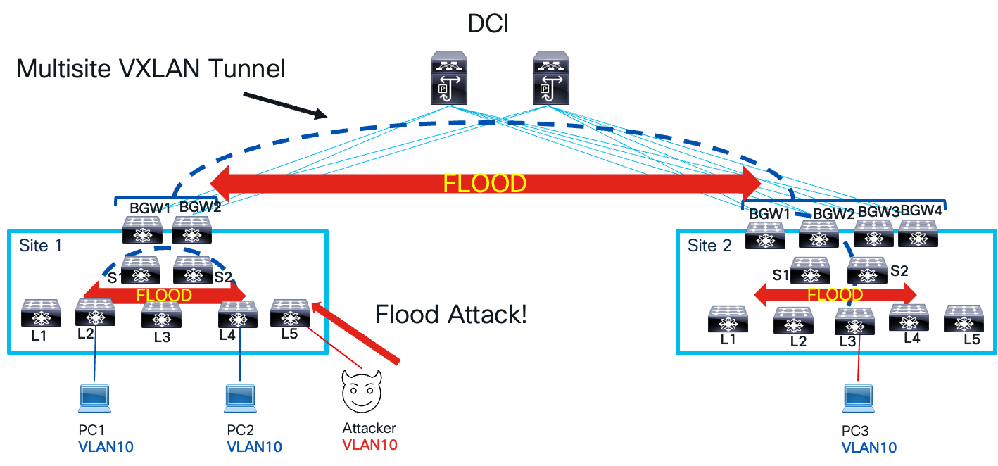
Flood Attack
To manage and mitigate the impact of traffic storms, excess traffic must be controlled within the network. In a VXLAN BGP EVPN network, two types of storm control are employed: interface storm control and EVPN storm control. These categories define the network points where traffic storm policing is applied. Interface storm control targets the access interface on the leaf node, the network’s entry point. EVPN storm control focuses on the fabric and data center interconnect (DCI) interface on the border gateway node, which serves as both the network’s entry and exit point. As traffic storms propagate from one local site to another across a multisite VXLAN tunnel interface, these control points ensure effective management. The image below illustrates the various control points and their respective names for storm control.
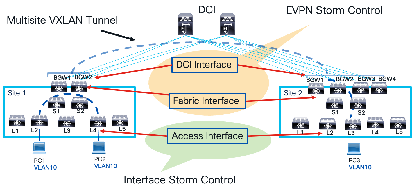
Storm Control Points
A few guidelines to take notes of as you implement interface storm control on leaf nodes.
● Can be configured on Physical, Port-Channel, and Breakout Interfaces.
● Only for ingress Unknown Unicast, Multicast, and Broadcast traffic.
Corrective actions include:
● Shutdown - Storm Control puts the port into the error-disabled state. Recommendation to use errdisable recovery cause storm-control and errdisable recovery interval command for automatic recovery.
● Trap - Generate an SNMP trap. Enabled by default. snmp-server enable traps storm-control trap-rate command to rate limit SNMP.
The below configuration example shows how to configure storm control on a leaf access interface for single level threshold.
// One-Level Threshold: 100 percent: No traffic Storm Control. 0.0 percent suppresses all traffic.
interface ethernet 1/1
storm-control unicast level 40
storm-control broadcast level pps 8000
storm-control action trap
In the above example, the unicast traffic is policed at 40 percent of the interface bandwidth. All traffic exceeding 40 percent of the interface bandwidth has dropped. The broadcast traffic is policed at 8,000 packets per second (PPS). In the event unicast or broadcast traffic violates the policing rate, the correction action is to send an SNMP trap.
The second example for access interface storm control shows how to specify a two-level threshold for storm control.
// Enable two-level threshold
system storm control multi-threshold
//Carve TCAM region
hardware access-list tcam region ing-storm-control 512
interface ethernet 1/1
interface ethernet 1/1
storm-control multi unicast level1 5 level2 10
storm-control multi action1 trap action2 shutdown
In the example above, unicast traffic policing is defined at two levels: level 1 and level 2. These levels represent minimum and maximum thresholds. If unicast traffic exceeds level 1 by 5%, a SNMP trap is sent as a corrective action. If traffic continues to rise and surpass level 2, which is 10% of the interface bandwidth, the interface is shut down.
The EVPN Storm control mitigates storms that occur when a VXLAN site leaves or enters a multisite VXLAN BGP EVPN network. It’s applied only to border gateway (BGW) devices. Here’s how it works:
● There are only ingress policers, and no egress policing is applied on the fabric or DCI interface.
● Slice-based Policing ensures a single policer can cater to multiple (DCI/Fabric) links.
● Multicast is not policed on the fabric side (e.g. On Site-1) but will be policed on DCI Side (e.g. On Site-2)
● Unknown Unicast Traffic Policer calculations are the same as Broadcast Traffic.
This configuration example demonstrates how EVPN storm control is applied to the DCI interface for multicast and broadcast traffic, assuming a policing rate of 10%.
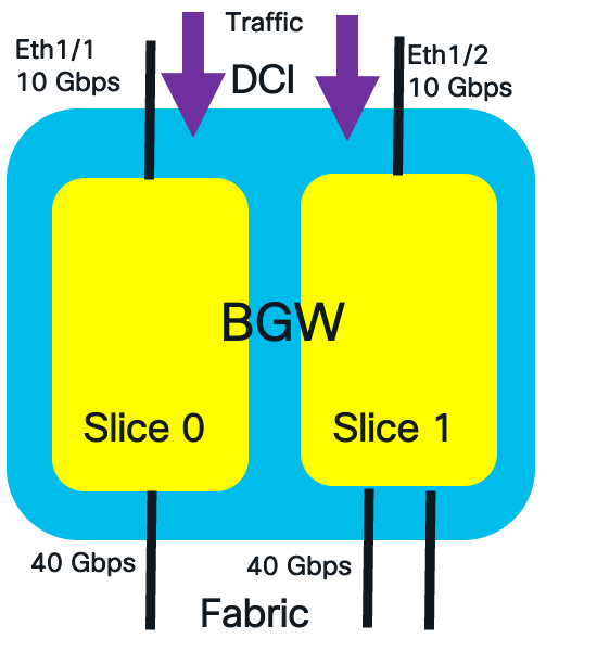
DCI Interface Traffic Policing
The formulate to calculate the policing rate on the DCI interface is the following:
DCI Link Side Policer Rate = Policer_Level * (DCI_Bandwidth[Slice])
The calculated policing rate for broadcast and multicast traffic are:
Multicast DCI Policer Rate = 10% of 10G = 1 Gbps
Broadcast DCI Policer Rate:10% of 10G = 1 Gbps
The commands to configure the policing rate at 10% for multicast and broadcast traffic on the DCI interface are shown below.
switch(config)#evpn storm-control multicast level 10
switch(config)#evpn storm-control broadcast level 10
The EVPN storm control is also applied in the ingress of the fabric interface. Multicast policers are not applied to on the fabric interfaces. The formula for fabric interface policer rate is:
Policer_Level * ((Fabric_Bandwidth[Slice]/Total_Fabric_Bandwidth)* Total_DCI_Bandwidth)
The below example depicts an EVPN storm control example for fabric facing interface with multiple slices.
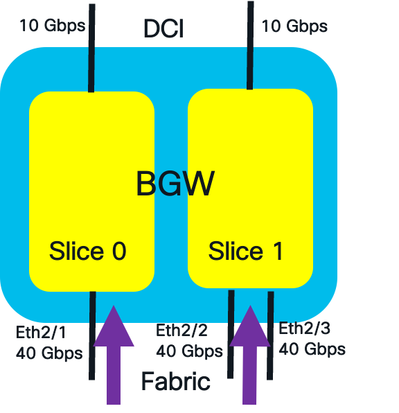
Fabric Interface Traffic Policing
The calculated policing rate for broadcast traffic per slice are:
Broadcast Fabric Interface Policer Rate Slice 0 = 10% of (40/120) * 20 = 0.66 Gbps.
Broadcast Fabric Interface Policer Rate Slice 1 = 10% of (80/120) * 20 = 1.33 Gbps
The commands to configure the policing rate at 10% for broadcast traffic on the fabric interface is shown below.
switch(config)# evpn storm-control broadcast level 10
To view detailed policer fabric and DCI interface rates, use show hardware vxlan storm-control command.
Southbound Loop Detection
A loop path in an Ethernet network occurs when multiple physical or logical paths exist between network devices, forming a circular connection. This causes Ethernet frames to endlessly forward in a loop. In a VXLAN network, a loop path arises from the forwarding of BUM traffic between the logical VXLAN tunnel and the physical layer two network at two access layer attachment points. The BUM traffic enters one access layer attachment point on the leaf, travels over the VXLAN tunnel to the remote leaf, and then is sent southbound to the same layer two network at another access layer attachment point.
Below are examples of layer-two connections that can cause a looped path in a VXLAN network.
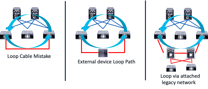
Southbound Looped Topologies
A network technician might accidentally connect two leaf switches back-to-back on interfaces forwarding traffic for the same VLAN, mapped to the same L2 VNI. This creates a loop in the traffic. Any BUM traffic sent in the same VLAN the back-to-back cable connects to will loop between the VXLAN tunnel and the southbound looped path. The reason for this endless looping is that Spanning Tree Protocol BPDUs are simply payload for the VXLAN tunnel. The VXLAN protocol does not interpret or act on these BPDUs, so the looped path is not detected like a STP-based Ethernet network.
The middle image in the figure illustrates a scenario where a switch or a transparent firewall connecting two interfaces can create a looped path. Additionally, a legacy network multihomed to a VXLAN network can also cause a loop. Any BUM traffic originating from the legacy network can traverse the VXLAN fabric and return to the legacy network through the redundant links connecting the two network domains.
Looped paths can also occur when extending layer two bridge domains between VXLAN BGP EVPN sites, as illustrated in the example below.
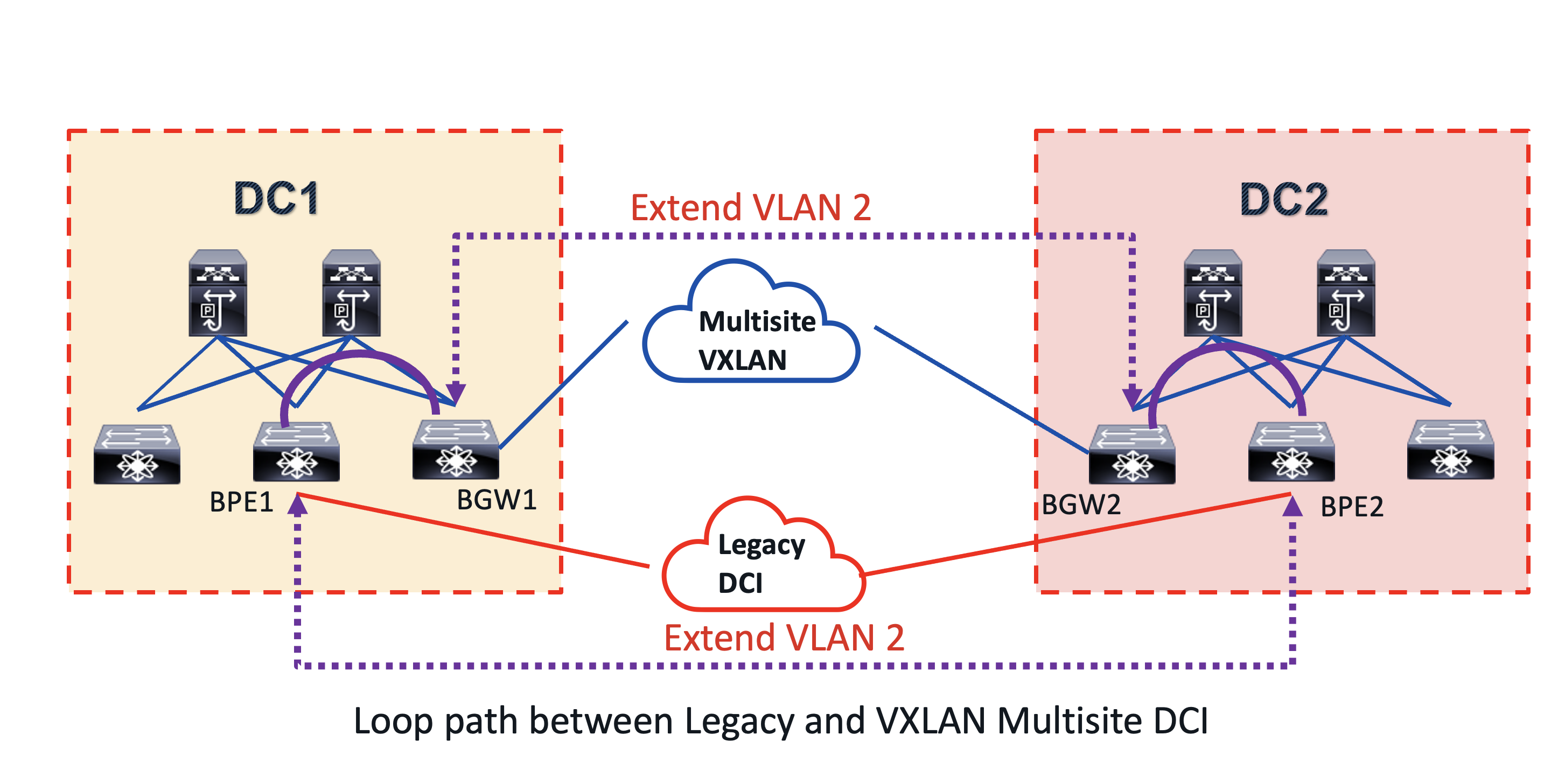
DCI Looped Topology
This topology illustrates a migration use case. Initially, DC1 and DC2, two VXLAN sites, used a legacy DCI like MPLS L2 VPN to connect their bridge domains. They then decided to switch to VXLAN BGP EVPN as a DCI overlay, simplifying the architecture by consolidating the control and data planes end-to-end. This new solution also offered the benefit of integrated routing and bridging (IRB) in a single overlay. During the migration from legacy DCI to the new multisite VXLAN BGP EVPN, a common VLAN 2 was extended within each site and between them, using both the multisite VXLAN and MPLS L2 VPN DCI. This created a looped path between the DCI, as shown by the purple dashed and solid lines in the diagram.
What is the impact of looped path in a VXLAN BGP EVPN network?
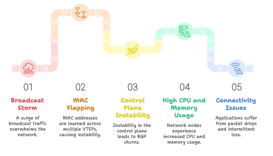
Network Loop Path Impact
The looped path can trigger the following:
01. A broadcast storm which multiplies and causes network congestion.
02. The broadcast storm will cause MAC flapping, leading to the same MAC address being learned across multiple Virtual Ethernet Protocols (VETPs). This introduces control plane instability.
03. Network nodes experience high CPU and memory usage due to control plane instability, such as BGP churns.
04. The instability of the control plane will lead to connectivity issues for host applications, such as packet drops and intermittent packet loss.
05. This broadcast storm will strain the CPU of endpoint devices due to the excessive broadcast traffic.
It’s crucial to implement mechanisms to prevent loop traffic, as it worsens traffic storms. Southbound loop detection (SLD) offers loop detection and mitigation for loops occurring on layer two and three connections south of the leaf nodes in a VXLAN fabric. These connections connect to a bridged STP-based network, and the detection and mitigation mechanism is the same for both layer two and three southbound leaf connections.
The SLD feature is part of the next-generation operation, administration, and maintenance (NGOAM) VXLAN features, specifically for connectivity and path validation. Its primary goal is to detect and mitigate loops as quickly as possible. While SLD does not prevent loops, it uses the IEEE 802.1ag Connectivity Fault Management (CFM) standard to identify them on the layer two network domains connected to the south side of leaf switches. The IEEE 802.1ag standard provides mechanisms for detecting, verifying, and isolating connectivity faults in Ethernet networks. This implementation is found in various Ethernet overlay solutions, including MPLS L2 VPNs and VXLAN. The CFM standard defines several messages and probes, including:
● Loopback Back Message (LBM) and Replies (LBR): Like a ping packet but for a layer two path in an ethernet network.
● Linktrace Messages (LTM) and Linktrace Replies (LTR): Like a traceroute packet but for layer two path in an ethernet network.
● Continuity Check Messages (CCM): A probe sent periodically by a device to test end to end connectivity.
The SLD feature on Cisco Nexus 9000 NXOS uses the CCM probe with following header format.

CCM Frame Header
The CCM probe is sent with ethernet type 0x8902. The destination MAC address is well known multicast MAC address 01-80-C2-00-00-37. The sender ID field is encoded with the sending leaf NVE primary IP address. The source MAC is encoded with the system MAC of the leaf. The CCM probes are only sent on VLANs mapped to layer 2 VNIs.
The SLD loop detection and mitigation function works in 3 phases.
Detection
The leaf L1 receives a CCM probe for each VLAN mapped to a layer 2 VNI. It compares the probe’s source address and VPC role to the leaf that sent it. If they match, it confirms a data plane loop.
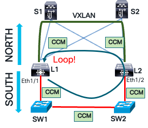
CCM Loop Detection
Mitigation
Leaf L1 blocks the VLAN associated with the port when it receives its own CCM message. This action flushes both local and remote MAC tables using a MAC flush message. This flush is necessary to clear any incorrect MAC learning that occurred during the loop. In Ethernet networks, as frames loop, the source MAC address is mapped to different switch interfaces. Consequently, the MAC address table is flushed on the local leaf and southbound layer two network devices.
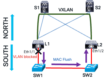
Loop Mitigation with MAC Flush
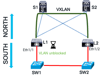
Recovery
If the CCM message is not received on leaf L1, the blocked VLAN on the southbound interface can be manually unblocked or recover automatically after a specified interval. Once the automatic recovery time passes, leaf L1 sends a CCM message. If the message is not received, the leaf L1 waits another recovery interval before unblocking the VLAN.
Loop Recovery
The steps to configure southbound loop detection are the following:
//Enable NGOAM feature
L1(config)# feature ngoam
////Enables/disables loop-detection for all VLANs/Ports. The loop detection would be disabled by default.
L1(config)# ngoam loop-detection
//This is the time-gap between sending two periodic probes. The default value is 300 seconds (5 minutes).
L1(config-ng-oam-loop-detection)# periodic-probe-interval 200
//To enable/disable SLD on a layer three ethernet interface, use the following command
L1(config-ng-oam-loop-detection)# l3 ethernet port Eth1/49
//To enable/disable SLD on a layer three port-channel interface, use the following command
L1(config-ng-oam-loop-detection)# l3 port-channel port port-channel1
The command to verify the SLD status.
show ngoam loop-detection status
VlanId Port Status NumLoops DetectionTime ClearedTime
=========================================================================
1000 Eth1/40 BLOCKED 13 Thu May 14 03:33:57 2020 Thu May 14 03:33:50 2020
The status column can report three states.
● BLOCKED: The VLAN or interface is administratively disabled due to loop detection.
● FORWARDING: No loop condition is present; the VLAN or interface is actively forwarding traffic.
● RECOVERING: CCM recovery probes are in progress to assess whether the previously detected loop condition persists.
MACsec
In certain industries, data transmission within and between data centers must be secured through encryption. For example, the healthcare industry mandates the protection of electronic protected health information (ePHI) during storage and transmission, as outlined by regulations like HIPAA (U.S.), GDPR (EU), and PIPEDA (Canada). Similarly, the finance and banking sectors require encryption of sensitive financial data, including credit card numbers and personal account information, as it travels over networks, following regulations such as PCI DSS, GLBA (U.S.), PSD2 (EU), and FFIEC guidelines. Government regulations like FISMA, FedRAMP, NIST SP 800-53, and DoD STIGs also mandate encryption of classified and sensitive government information across public and private networks. Public networks encompass any network not managed by a government entity, such as a service provider.
The Media Access Control security (MACsec) protocol solves the problem of data in transit in an Ethernet network. The diagram below illustrates a problem of securing data in transit in a data center environment.
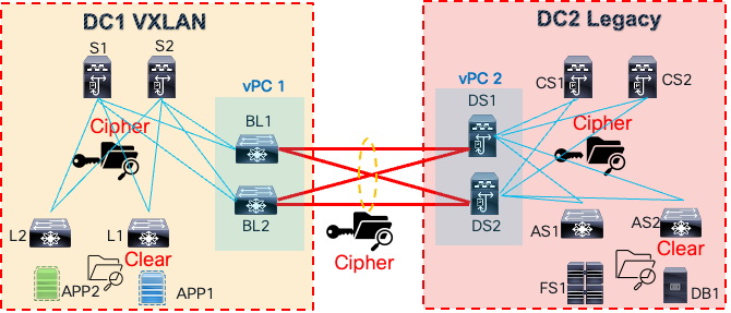
Inter DC Traffic Encryption
There are two data centers: a VXLAN data center (DC1) and a legacy data center (DC2). A back-to-back vPC data center interconnect connects the networks between the sites. The application tier has been moved to DC1’s VXLAN site, but the database and file system servers remain in DC2. The application needs access to these servers in DC2. This access must be secure, as data and files transit between the sites, preventing unauthorized access through cable tapping or insider threats.
The MACsec protocol, a data link layer protocol, offers encryption, integrity, replay protection, and authentication for Ethernet frames between directly connected MACsec-enabled devices. It’s based on the IEEE 802.1AE standard. As shown below, MACsec encrypts frames hop by hop.
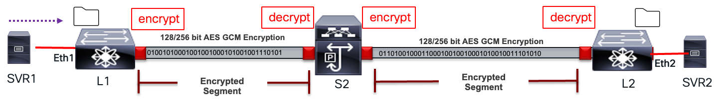
MACsec Link Level Encryption
The packet undergoes processing at each hop as described below:
● Packets are decrypted on ingress port (MACsec PHY)
● Packets are clear through the device.
● Packets are encrypted on egress port (MACsec PHY)
MACsec is widely used in data center interconnect (DCI), east-west traffic encryption within data centers, enterprise LANs, and campus networks. Its benefits include:
● Encryption at data link layer; transparent to Layer-3 transport (IPv4/v6, SR, MPLS, VXLAN).
● Prevent Layer-2 security threats, such as passive wiretapping, denial of service, intrusion, man-in-the-middle, and playback attacks.
● Simplified per port line-rate encryption with no dependency on centralized ASIC with lower encryption rates, such as an IPsec engine.
● The traffic transiting node is not encrypted, providing flexibility for services such as QoS, Layer-4 to Layer-7 services.
● Strong cryptographic security with protocols such as AES-GCM-128/256.
The MACsec suite of protocols provides secure data in transit. A key component of MACsec is the MACsec Key Agreement (MKA) protocol, defined in the IEEE 802.1XREV-2010 Port-Based Network Access Control standard. MKA’s primary function is to facilitate peer discovery, authentication, key negotiation, session key creation, encryption key generation, and session maintenance. Its significance lies in offering an interoperable, dynamic key exchange standard, eliminating error-prone and insecure manual key management methods.
The table below explains the terminologies used in MACsec. These terms will be referenced when explaining the MKA encryption process.
Table 4. MACsec Terminology
| MACsec Term |
Definitions |
| Connectivity Association (CA) |
Security relationship between MACsec nodes that use the same key and key encryption algorithms. Same CAK is used between nodes in the same CA. |
| Connectivity Association Key (CAK) |
Generated by PSK, MSK or Key Server. Long live key used to generate all other keys ICK, KEK, and SAK. |
| Connectivity Association Key Name (CKN) |
Identified the CAK. Mutual Authentication based on CAK and CKN. |
| Secure Association Key (SAK) |
Data traffic encryption key. Derived from CAK. |
| Key Encryption Key (KEK) |
Used to encrypt SAK. |
| Integrity Check Key (ICK) |
Key used for Integrity Check Value (ICV). |
The MKA encryption process involves session negotiation, encrypted communication, and maintaining a session keep-alive state. Each of these states has its own specific processes.
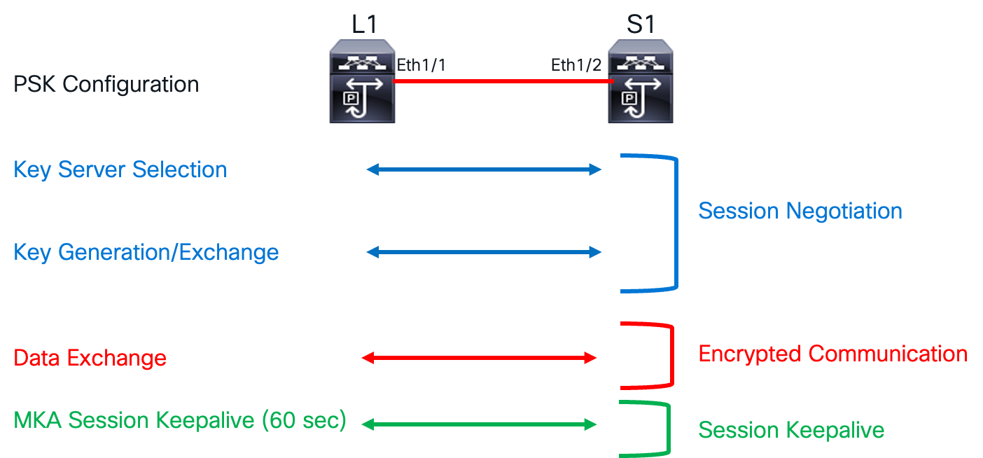
MKA Encryption Process
The Connectivity Association (CA) defines a group of MACsec nodes that can securely communicate with each other. These nodes establish a master-slave relationship, with the master acting as the key server that initiates the session negotiation process. Members of a CA authenticate to one another using IEEE 802.1X. The CA is uniquely identified by a long-lived key called the Connectivity Association Key (CAK), and the Connectivity Association Key Name (CKN) serves as an identifier for the CAK. The CAK can be configured using either the pre-shared key method or a key server. Both the CAK and CKN are essential for establishing a connectivity association between two peers.
The CAK, or seed key, is used to derive the security association key (SAK). This SAK encrypts data traffic. Since the SAK must be securely exchanged between peers, it’s also encrypted. The key encryption key (KEK) encrypts the SAK to ensure secure exchange. To maintain data integrity, an integrity check value (ICV) header is appended to the Ethernet frame. The integrity check key (ICK) computes the ICV value. The MKA session keep-alive supports session liveliness between peers.
The steps to configure MACsec are much simpler than the technology underneath.
Step 1. Enable MACsec.
switch(config)# feature macsec
Step 2. Create MACsec Keychain.
//Creates a MACsec keychain.
switch(config)# key chain <name> macsec
// Creates a MACsec key
switch(config-macseckeychain)# key <CKN>
//Configures the octet string for the key.
switch(config-macseckeychain-macseckey)# key-octet-string <CAK> cryptographic-algorithm {AES_128_CMAC|AES_256_CMAC}
//Configures a send lifetime for the key.
switch(config-macseckeychain-macseckey)# send-lifetime <Timestamp> {duration|infinite}
Step 3. Create MACsec Policy.
// Creates a MACsec policy.
switch(config)# macsec policy <policy name>
//Configures the sequence for the following cipher suites from the most preferred to the least preferred.
switch(config-macsec-policy)# cipher-suite <GCM-AES-128|GCM-AES-XPN-128| GCM-AES-256| GCM-AES-XPN-256>
//Configures the key server priority to break the tie between peers during a key exchange and SAK expiry time.
switch(config-macsec-policy)# key-server-priority <0-255>
switch(config-macsec-policy)# sak-expiry-time <60-2592000>
Step 4. Apply MACsec policy to interface.
switch(config)# interface Ethernet 1/21
switch(config-if)# macsec keychain <name> [ policy <name> ]
Quantum Key Distribution for MACsec
Physics proposed a solution called Quantum Key Distribution (QKD), most famously the Bennett-Brassard 1984 protocol. QKD uses the unique property of quantum particles to create and transmit a secure key. This is intriguing because a quantum particle’s state cannot be copied, making it inherently possible to verify the security of the transmitted key. To truly grasp quantum computing power and quantum key distribution, we must first understand qubits and entanglement. In quantum mechanics, a qubit is the fundamental unit of quantum information, akin to the classical binary bit. Unlike classical bits, qubits can exist in a coherent superposition of multiple states. Let’s delve into what this means.
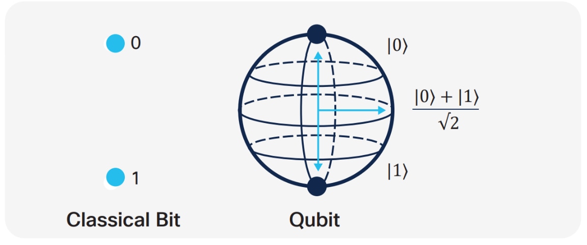
Quantum Key Distribution for MACsec
Secure Key Integration Protocol
Cisco has developed a protocol called the Secure Key Integration Protocol (SKIP). This protocol allows any Cisco device that supports encryption to utilize keys provided by a quantum distribution system. Two locations and two encrypting routers are involved, one in each location. Each encrypting router is co-located with a key provider, and these key providers communicate using the same principles as quantum key distribution.
Quantum computing has exposed weaknesses in cryptographic algorithms like RSA and DHE, which rely on computational complexity. Quantum computers could exploit these vulnerabilities using Shor’s or Grover’s algorithm, making secure key exchange difficult. To address this, use quantum-safe algorithms or implement Quantum Key Distribution (QKD).
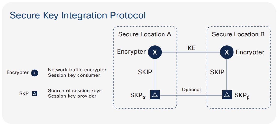
SKIP Protocol
Integrating the SKIP protocol into switches enables communication with external quantum devices. This advancement allows for the use of Quantum Key Distribution (QKD) devices to exchange MACsec encryption keys between switches.
QKD is a secure key exchange mechanism that protects against quantum attacks, even as cryptanalysis or quantum computing technology advances. It does not require constant updates based on discovered vulnerabilities.
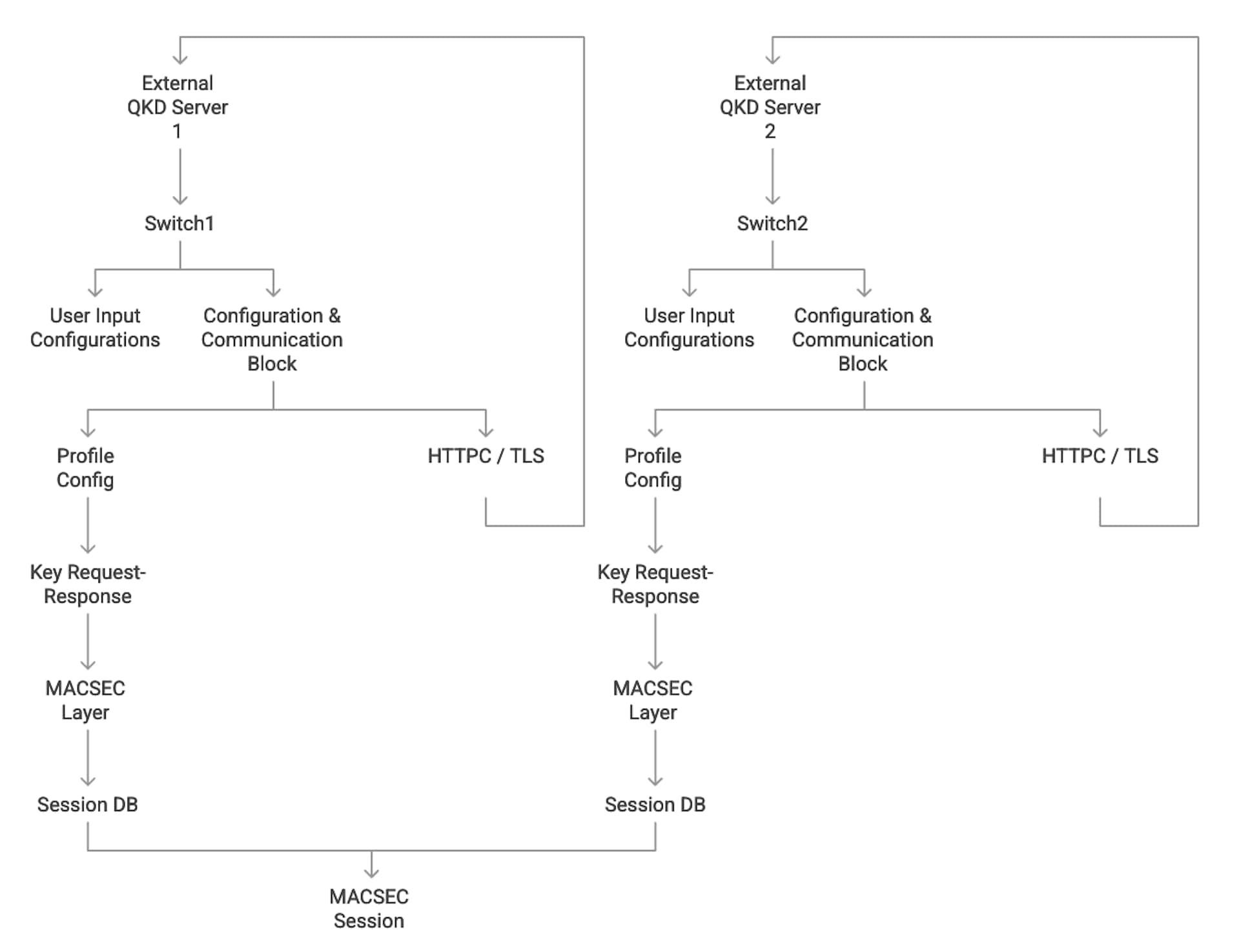
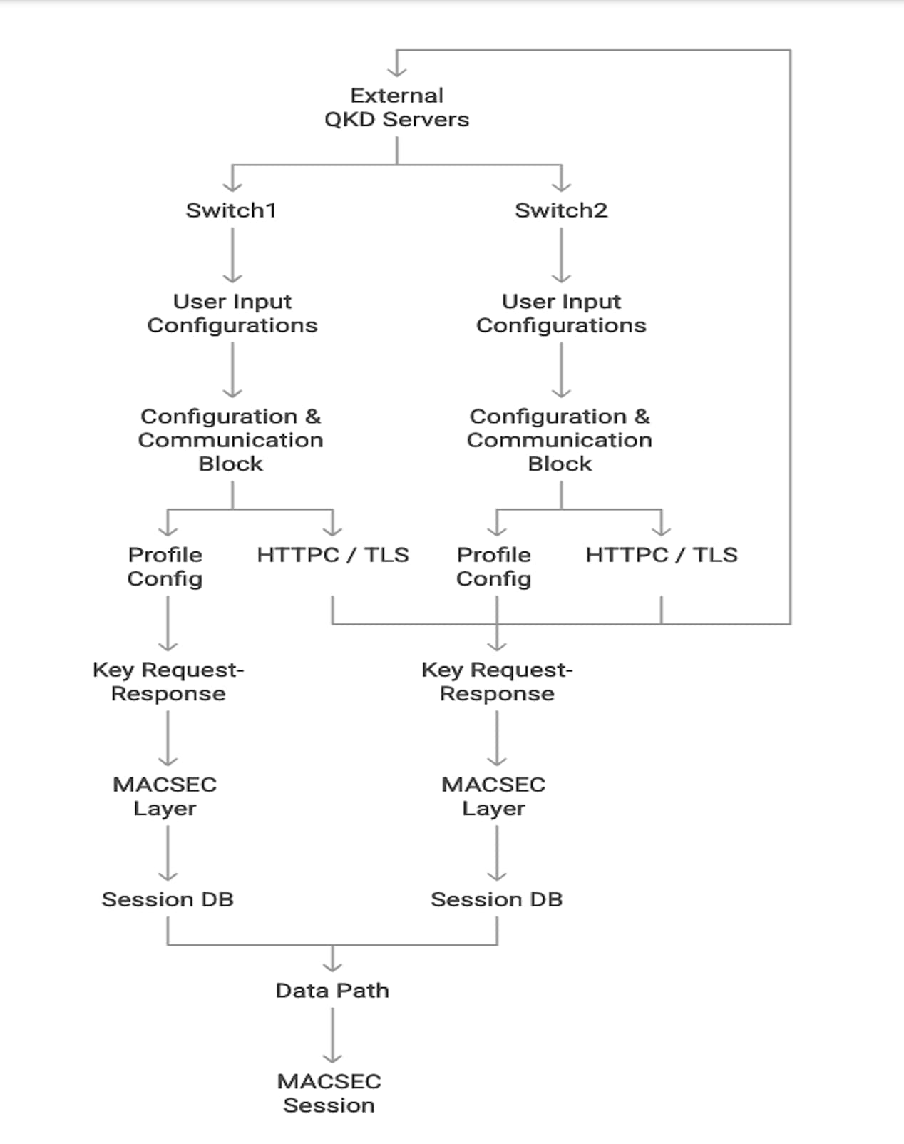
QKD and MACsec Integration Architecture
In Point-to-Point MACsec Link Encryption, secure encryption is established between two interfaces on peer switches using SKIP in switches. This encryption requires a QKD device network for key exchange. Instead of sharing the MACsec encryption key through the switch network, the QKD network facilitates this key exchange. When a switch needs to create a MACsec link, it contacts the external QKD device to request the key. The external QKD device then generates a key pair, consisting of the Key ID and the Key itself.
The Key ID uniquely identifies the shared secret key. During Quantum Key Distribution (QKD), the QKD device shares the Key ID and key with the switch. The switch only shares the Key ID with its peer, which retrieves encryption keys from its QKD device using the Key ID. This ensures secure communication of encryption keys in quantum networks.
QKD and MACsec Integration Architecture – Key Sharing
BGP EVPN Remote Triggered Black Hole
Service provider networks are constantly under attack. These networks sell bandwidth, and Distributed Denial of Service (DDoS) attacks are common. DDoS attacks consume all available bandwidth, disrupting customer traffic and harming the service provider’s ability to deliver services. To combat these attacks, service providers introduced BGP remote-triggered blackholing in their core networks. The goal was simple: drop any malicious traffic originating from a specific source or destination as close to the source as possible, minimizing the impact on the internal network or systems. BGP achieves this by advertising a route to null0 using a well-known blackhole community, prompting network devices to drop traffic matching the malicious IP address.
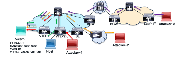
DDOS Attack
The VXLAN BGP EVPN Route-Based Redundancy (RTBH) solution is similar to the traditional BGP RTBH method used in service provider networks. However, it applies to the BGP EVPN address family, not the IPv4, IPv6, VPNv4, or VPNv6 address families. While conventional BGP RTBH mitigates DDoS attacks within a service provider’s core network, VXLAN BGP EVPN RTBH specifically targets attacks within the VXLAN overlay network. The BGP EVPN address family also includes a well-known blackhole community for BGP EVPN Type 2 (MAC/MAC-IP) and Type 5 (prefix) routes, as defined in RFC 7999 and RFC 5635. The IANA has assigned the BGP EVPN blackhole community value of 0xFFFF029A (lower two octets = 666).
Benefits of BGP EVPN RTBH
The benefits of BGP EVPN RTBH are captured in the table below.
Table 5. BGP EVPN RTBH Benefits
| EVPN RTBH Benefits |
Description |
| Stops attacks quickly |
Near-instant with good detection mechanisms and automated BGP announcements. |
| Fabric-wide advertisement |
Blackhole route can propagate across sites to other autonomous systems mitigating attacks across entire network. |
| Prevent Collateral Damage |
Drops traffic of the victim only instead of blackholing entire network. |
| Works with VXLAN overlay |
No need to change the underlay network design or configuration. Is implemented only on the overlay selectively per VRF and network. |
Mitigation of BGP EVPN RTBH
The BGP EVPN RTBH mitigates DDOS attacks with the following steps:
Step 1. Detect the attack and victim.
A monitoring or detection system such as sFlow, NetFlow, DDoS appliance, or IDS is used to identify any traffic anomaly in the network, the victim, and/or source of the malicious traffic.
Step 2. Trigger the Blackhole.
The black hole is triggered by creating a route to the null interface only on the trigger router. A null interface is a logical interface that acts as a bit bucket to drop packets. A null route can be created destined to a particular host, as shown below, with the step to dynamically advertise the null route from the trigger router using BGP.
//On Trigger Router Null route to routed host MAC-IP
VTEP1(config)# mac address-table static 0001.0001.0001 vlan 10 drop
VTEP1(config)# interface vlan 10
VTEP1(config-if)# ip arp 10.1.1.1 0001.0001.0001
Note: For a bridged traffic to a particular host that needs to be dropped will not need a static ARP entry but just MAC entry with action drop. For example, “mac address-table static 000A.000B.000C vlan 5 drop”.
A null route for a destination prefix is shown below with the step to dynamically advertise the null route from trigger router using BGP.
//On Trigger Router Null route to destination network.
VTEP1(config)# vrf context L3-VXLAN-VRF-001
VTEP1(config-vrf)# ip route 10.1.1.0/24 null0 tag 6666
VTEP1(config)# route-map BH-RMAP-SEND permit 10
VTEP1(config-route-map)# match tag 6666
VTEP1(config-route-map)# set weight 65535
VTEP1(config-route-map)# set community blackhole
VTEP1(config)# router bgp 100
VTEP1(config-router)# vrf L3-VXLAN-VRF-001
VTEP1(config-router-vrf)# address-family ipv4 unicast
VTEP1(config-router-vrf-af)# redistribute static route-map BH-RMAP-SEND
On all the VTEPs including the trigger router the following BGP configuration is applied.
A. One-time configuration is applied on all VTEPs to assign the highest weight for routes with Blackhole Community.
// Configure a named community list
VTEP(config)# ip community-list standard BH seq 10 permit blackhole
// Create a Route-map, match the blackhole community
VTEP(config)# route-map BH-RMAP-RECV permit 10
VTEP(config-route-map)# match community BH
VTEP(config-route-map)# set weight 65535
B. Apply the route-map matching routes with blackhole community on all the VTEPs under the BGP process in the ingress direction.
router bgp 100
router-id 10.1.0.13
address-family l2vpn evpn
template peer LEAF_to_FABRIC_IBGP_OVERLAY
remote-as 100
address-family l2vpn evpn
send-community
send-community extended
route-map BH-RMAP-RECV in
neighbor 10.1.0.31
inherit peer LEAF_to_FABRIC_IBGP_OVERLAY
Step 3. All Routers Install Null Route.
The VTEPs in the VXLAN fabric learn the EVPN Type 2 or Type 5 route with blackhole community which triggers installation of null route entry dropping all traffic destined to the victim.
PVLAN over VXLAN
In today’s datacenter landscape, workloads reside in virtual environments. Due to business requirements for high availability and workload mobility, these workloads are scattered across multiple sites. This creates a security challenge, raising the question: can I achieve perfect segmentation and security simultaneously by extending Private VLANs (PVLANs) across VXLAN sites?
PVLANs need to be extended over the VXLAN EVPN fabric to enable scalable and secure Layer 2 network segmentation across multiple Ethernet switches within the VXLAN overlay. This extension allows for the partitioning of a regular VLAN into logical subdomains, providing Layer 2 isolation between ports, even when those ports connect to different VXLAN Tunnel End Points (VTEPs) across the fabric.
Furthermore, extending PVLANs conserves IP subnet usage across the VXLAN EVPN fabric. It allows segregated Layer 2 networks to span the fabric without requiring additional subnets. This extension also facilitates seamless migration and stretching of PVLAN domains across the VXLAN EVPN fabric, enabling access to centralized common services like DHCP and printers through promiscuous ports on any VTEP.
Extending private VLANs over a VXLAN EVPN fabric offers scalable, secure, and efficient Layer 2 isolation and segmentation. This is crucial for modern data center architectures that demand micro-segmentation and multi-site connectivity.
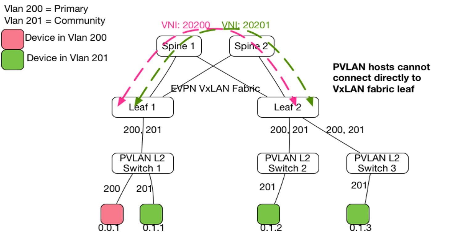
PVLAN over VXLAN Topology
Layer 2 MAC address learning happens within the primary VLAN or VNI. When Layer 2 data traffic arrives on a secondary VLAN, it’s carried across the VXLAN fabric with the secondary VNI included in the VXLAN header. However, MAC learning and forwarding decisions remain within the primary VLAN or VNI context. The mapping between the secondary VLAN and the primary VLAN ensures MAC address lookups occur in the correct Bridge Domain (BD) context, maintaining typical Private VLAN (PVLAN) behavior. Every VLAN, whether primary or secondary, must have an associated VN-segment (VNI) configured under the NVE interface to be transmitted over the VXLAN fabric.
The SVI (Switched Virtual Interface) acting as the gateway for the PVLAN group must be connected to the VRF associated with a Layer 3 VNI to enable VXLAN routing between different VLANs or VNIs. Since VLANs operate in a switch-local context, while VNIs have a global context, the same VNI can be mapped to different VLANs on different VTEPs. This behavior is common to VXLAN and not specific to PVLANs.
Private VLANs (PVLANs) enhance data center security by segmenting Layer 2 traffic within a single VLAN. This segmentation restricts communication between devices sharing the same VLAN, limiting unauthorized or unnecessary interactions. This is particularly important in multi-tenant or shared environments.
PVLANs divide a primary VLAN into multiple isolated broadcast domains, known as secondary VLANs, such as isolated and community VLANs. Devices within isolated VLANs cannot communicate with each other but can connect to promiscuous ports like routers or firewalls, effectively preventing lateral threat movement. Community VLANs, on the other hand, allow communication among their members and with promiscuous ports, but block communication with other VLANs. This setup enables secure grouping of devices.
Promiscuous ports connect to all devices within the PVLAN, usually linking to gateways or security devices to control access. This configuration enforces Layer 2 segmentation, ensuring that host-to-host communication must pass through the gateway, where additional security policies can be applied. PVLANs also help contain the impact of compromised devices by restricting lateral movement and supporting multi-tenant environments by isolating clients or servers on shared infrastructure without the need for numerous VLANs.
Overall, PVLANs enhance data center security by providing strict Layer 2 isolation and controlled communication paths, thereby reducing attack surfaces and improving segmentation efficiently.
Features like VXLAN GPO further enhance security and segmentation when these PVLANs are extended across a VXLAN fabric with granular policies. This supports zero-trust models and fine-grained control over east-west traffic.
Control Plane Security in VXLAN Fabrics
The control plane manages CPU routing protocols, mac address learning, topology discovery, ARP, Network Discovery (ND), and network policy enforcement and management protocols like SSH, SNMP, Netconf, Syslog, and others. It’s essentially the brain of a network device. Think of it like the brain of a human body: if it malfunctions, the rest of the body ceases to function and enters a coma. Similarly, if the control plane of a network device fails, it can’t process any packets. Therefore, protecting the control plane is crucial.
● The control plane is CPU-based, making it vulnerable to attacks that exhaust CPU and memory, such as ICMP floods (ping of death), BGP spoof packets, or routing update storms. Protecting the control plane prevents loss of routing adjacencies and ensures the network remains operational.
● The control plane manages protocols like SSH/Telnet, SNMP, Syslog, NTP, Netconf/Restconf, RADIUS, and TACAC+. Protecting it ensures only trusted hosts can access it, preventing complete device access loss.
There are many methods available to protect the control plane. Some of the methods are summarized in the below table.
Table 6. Control Plane Protection Methods
| Method |
Example |
Purpose |
| Control Plane Policing |
Policy Map applied to control plane. |
Filter and Police traffic punted to the CPU of the network device. |
| Access Control List |
Access List applied to SSH, Telnet, NTP, SNMP servers. |
Restrict who can reach management protocol ports and initiate sessions. |
| Routing Protocol Authentication |
BGP/ISIS/OSPF passwords and key chains. |
Prevent rogue routers peering and exchanging spoofed messages. |
| Out of Band Management Network |
No inband management of infrastructure. |
Separation of production data and infrastructure management traffic. |
| Switch Hardening |
Disable telnet |
Disable unused services and vulnerable protocols that can be used as attack vector. |
Securing the control plane is foundational to securing the network. The next section explains one of the methods, control plane policing.
Control Plane Policing
Control plane policing (CoPP) is a security and performance mechanism that classifies, rate-limits, or drops traffic directed to a network device’s control plane. Think of CoPP as a firewall for the routers or switch’s CPU, ensuring critical control traffic is prioritized and protected from overload and crashes. Without CoPP policy, malicious or accidental traffic can overwhelm the network device’s CPU, causing network instability or outages.
In a VXLAN BGP EVPN network, common control plane activity includes large routing updates from an external router, a high number of servers provisioned simultaneously through the virtual machine manager, or a large number of multicast streams sending traffic to many receivers at once.
Several types of packets that reach the control plane include:
Receive packets: Packets destined for local processing on the device’s network. These packets can have either a Layer 2 address (like a router’s MAC address) or a Layer 3 address (like a router’s IP address). Examples of received packets include ARP requests and replies, ICMP echo requests (ping), routing protocol packets, SSH/Telnet sessions, and NTP requests.
Exception packets: In a network device, exception packets are packets that would typically be handled in the data plane. However, due to the hardware forwarding ASIC’s inability to process them, they’re redirected (“punted”) to the control plane for software processing by the CPU. Common examples of exception packets include incomplete ARP resolution, packets with a TTL of 1, packets exceeding the Maximum Transmission Unit (MTU) with the Don’t Fragment (DF) bit set, ICMP redirect enabled, or IP options requiring CPU processing.
Redirected packets: This is a type of exception packet intercepted by the control plane, allowing the device to generate and send an ICMP Redirect message back to the source host.
Glean packets: This is a type of exception packet used for ARP (IPv4) and Neighbor Discovery (ND) in IPv6. If a Layer 2 MAC address for a destination IP address isn’t in the hardware forwarding table, the control plane process (ARP or ND) receives the packet and sends an ARP request or ND Neighbor Solicitation (NS) message to the host.
Regardless of the control plane protocol, all of them need to go through a punt path to the CPU to get processed as illustrated in the below diagram.
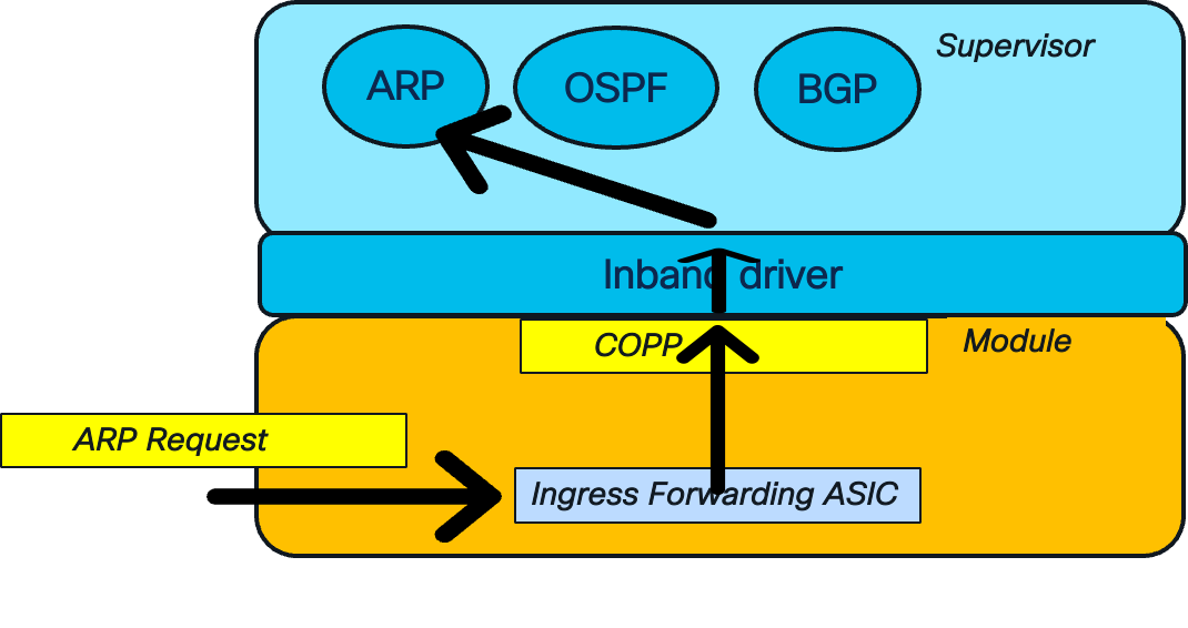
CoPP Punt Path
The network device receives the ARP request. This control plane packet requires CPU management. The ingress forwarding ASIC, a hardware forwarding engine, identifies the ARP packet by its Ethernet type value. It then sends the packet to the control plane for processing. The control plane inspects the packet type and rate-limits the traffic before sending it to the CPU. This rate-limiting is crucial for preventing a DOS attack that could overwhelm the network device’s CPU. Once the traffic is permitted, it passes through the in-band driver to the appropriate control plane ARP process.
The Nexus 9000 NX-OS platform offers four CoPP profiles: strict, moderate, lenient, and dense. The strict profile enforces a lower threshold for rate limits on traffic directed to the CPU. This results in lower committed burst and rate limit values, causing traffic to drop sooner during high CPU load. Conversely, the lenient policy has a higher rate limit threshold, allowing traffic to drop later and providing more room for CPU consumption to increase. This lenient policy is designed for less restrictive environments like labs and development networks where high traffic volume is expected and functionality is prioritized over security. Only one CoPP profile can be applied at a time, and the default is strict (copp-system-p-policy-strict).
The below example shows an example configuration of a CoPP profile on NX-OS platform. The NX-OS switches also use the modular QoS structure for cli with class-maps and policy-maps.
//ACL definition. For example: Match by Dest-UDP-port with a value of “bootpc” => bootstrap protocol client = 67. This is the DHCP client ACL
ip access-list copp-system-p-acl-dhcp
permit udp any eq bootpc any
//DHCP class-map definition to match the DHCP client ACL
class-map type control-plane match-any copp-system-p-class-normal-dhcp
match access-group name copp-system-p-acl-dhcp
//policy-map definition to match the DHCP class-map and take policing action.
NOTE: This policy-map is attached to the Control Plane Interface.
policy-map type control-plane copp-system-p-policy-strict
class copp-system-p-class-normal-dhcp
set cos 1
police cir 1300 kbps bc 32000 bytes conform transmit violate drop
To view what CoPP policy is applied on the control plane.
Switch1# show policy-map type control-plane
policy-map type control-plane copp-system-p-policy-strict !Strict policy
class copp-system-p-class-l3uc-data !Class-type
set cos 1 !Action: set cos + police.
police cir 800 kbps bc 32000 bytes conform transmit violate drop
class copp-system-p-class-critical
set cos 7
police cir 36000 kbps bc 1280000 bytes conform transmit violate drop
class copp-system-p-class-important
set cos 6
police cir 2500 kbps bc 1280000 bytes conform transmit violate drop
To verify which packets are dropped due to CoPP.
Switch# show policy-map interface control-plane
Control Plane
Service-policy input: copp-system-p-policy-strict
class-map copp-system-p-class-l3uc-data (match-any)
match exception glean
set cos 1
police cir 800 kbps , bc 32000 bytes
module 1 :
transmitted 817461791 bytes; !confirming packets sent
5-minute offered rate 99932 bytes/sec
conformed 100238 peak-rate bytes/sec
at Fri Jan 24 07:59:04 2025
dropped 644216901912 bytes; !violating packets dropped
5-min violate rate 78515894 byte/sec
violated 87805944 peak-rate byte/sec
Securing both the VXLAN underlay and overlay is crucial for ensuring infrastructure availability and application reachability within a data center. This is especially important in mission-critical environments where VXLAN BGP EVPN is used to support workloads. Robust security measures must be enforced across the endpoint, control plane, and data plane.
Cisco Nexus 9000 series switches running NX-OS offer a comprehensive set of security features designed to mitigate threats at multiple layers. These include Storm Control, which contains broadcast, multicast, and unknown unicast traffic; Loop Detection, which prevents Layer 2 forwarding anomalies; Control Plane Policing (CoPP), which rate-limits CPU-bound traffic; and Distributed Denial-of-Service (DDoS) mitigation using BGP Remote Triggered Black Hole (RTBH) filtering. First Hop Security (FHS) features like DHCP snooping, Dynamic ARP Inspection (DAI), and IP Source Guard protect against spoofing and man-in-the-middle attacks at the host access layer. Together, these features create a defense-in-depth strategy to secure the VXLAN fabric and maintain data center resiliency.
Cisco and the Cisco logo are trademarks or registered trademarks of Cisco and/or its affiliates in the U.S. and other countries. To view a list of Cisco trademarks, go to this URL: https://www.cisco.com/c/en/us/about/legal/trademarks.html. Third-party trademarks mentioned are the property of their respective owners. The use of the word partner does not imply a partnership relationship between Cisco and any other company. (1721R)
Any Internet Protocol (IP) addresses and phone numbers used in this document are not intended to be actual addresses and phone numbers. Any examples, command display output, network topology diagrams, and other figures in the document are shown for illustrative purposes only. Any use of actual IP addresses or phone numbers in illustrative content is unintentional and coincidental.
© 2026 Cisco Systems, Inc. All rights reserved.