Extending Kubernetes Clusters with Cisco NX-OS VxLAN and Calico
Available Languages
Bias-Free Language
The documentation set for this product strives to use bias-free language. For the purposes of this documentation set, bias-free is defined as language that does not imply discrimination based on age, disability, gender, racial identity, ethnic identity, sexual orientation, socioeconomic status, and intersectionality. Exceptions may be present in the documentation due to language that is hardcoded in the user interfaces of the product software, language used based on RFP documentation, or language that is used by a referenced third-party product. Learn more about how Cisco is using Inclusive Language.
- US/Canada 800-553-2447
- Worldwide Support Phone Numbers
- All Tools
 Feedback
 Feedback
With the proliferation of container networking, Kubernetes is the orchestrator of choice for a cloud-native, scalable, highly available, and flexible architecture. Calico’s open-source connectivity and security solution is becoming a widely used deployment choice. Calico’s plugin for Kubernetes offers network connectivity for eBGP, IP in IP, etc.
Cisco NX-OS and VXLAN when used in conjunction with Calico, it allows for the creation of a highly scalable and secure network infrastructure. VXLAN provides the means to create multiple virtual networks within a single physical infrastructure, while Calico enables the configuration of network policies to control access and communication between these virtual networks. In addition, Calico can be integrated with other network infrastructure and security tools, such as firewalls and load balancers, to provide an even more robust and secure network.
Prerequisites
This document assumes the reader is familiar with the basic concepts of Kubernetes and Calico. This document mainly focuses on design considerations with examples of the configuration of related components.
In Kubernetes orchestrator, each POD (short for "pod" or "process on a descriptor") is a logical host for one or more containers, and each POD is associated with a unique IP address. This makes communication between PODs within a Kubernetes cluster relatively simple, as the PODs can directly communicate with each other using their IP addresses.
When the Kubernetes clusters are connected to a VxLAN (Virtual Extensible LAN) fabric, they can advertise all of their service networks to the VxLAN fabric. This allows the PODs within the clusters to communicate with each other, as well as with other PODs and services that are connected to the VxLAN fabric. The VxLAN fabric offers Layer 3 segmentation using VRF (Virtual Routing and Forwarding) between PODs.
NX-OS Calico Network Topology
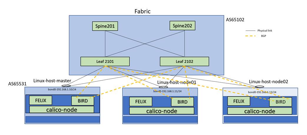
Note: Linux master, Linux-node01 and Linux-node02 are Calico Network infrastructure.
Spine and Leafs are VXLAN Fabric
IP allocation schema
● Anycast gateway IP 192.168.1.1/24 and IPv6 2001:192:168:1::1/64
● Bond0 IP on master node 192.168.1.10/24 and ipv6 2001:192:168::10/64
● Bond0 IP on node01 192.168.1.11/24 and ipv6 2001:192:168:1::11/64
● Bond0 IP on node02 192.168.1.13/24 and ipv6 2001:192:168:1::13/64
● Fabric BGP AS 65102 and Kubernetes/Calico Cluster AS 65531
Service Leaf Network Design
BGP peering is enabled between the Service leaf and Kubernetes open-source CNI framework (Calico). The Kubernetes nodes are connected to the VxLAN fabric with a pair of leaf switches for redundancy. Although both physical and fabric peering vPC are supported. The leaf switches are configured for vPC fabric peering in this case study. A unique loopback IP address is created for each pair of service leaf switches (Leaf 2101 and Leaf 2102) to peer with the calico node.
Loopback on Leaf2101
interface loopback1002
vrf member gr-vrf-001
ip address 192.168.100.1/32 tag 6789
ipv6 address 2001:193:168:1::4/128
Loopback on Leaf2102
interface loopback1002
vrf member gr-vrf-001
ip address 192.168.100.2/32 tag 6789
ipv6 address 2001:193:168:1::5/128
BGP peering towards the calico node is with loopback1002 as the source IP and the BGP neighbor IP address is the directly connected subnet of the SVI associated with the VRF.
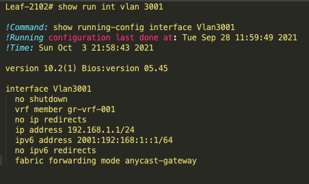
SVI interfaces on Leaf2101 and Leaf2102
interface Vlan3001
no shutdown
vrf member vrf-001
no ip redirects
ip address 192.168.1.1/24
ipv6 address 2001:192:168:1::1/64
no ipv6 redirects
fabric forwarding mode anycast-gateway
BGP configuration of Leaf2101
Router bgp 65102
template peer CALICO
remote-as 65531
update-source loopback1002
ebgp-multihop 10
address-family ipv4 unicast
as-override
template peer K8-v6
remote-as 65531
update-source loopback1002
ebgp-multihop 10
address-family ipv6 unicast
as-override
vrf vrf-001
neighbor 192.168.1.10
inherit peer CALICO
address-family ipv4 unicast
neighbor 192.168.1.11
inherit peer CALICO
address-family ipv4 unicast
neighbor 2001:192:168:1::10
inherit peer K8-v6
neighbor 2001:192:168:1::11
inherit peer K8-v6
neighbor 2001:192:168:1::13
inherit peer K8-v6
"as-override" config is necessary when all of the Calico nodes in a fabric are configured with the same AS.
It replaces the remote AS (Autonomous System) number with the local AS number in BGP (Border Gateway Protocol) updates. The peer IP addresses are on the same subnet as the anycast SVI (switch virtual interface)
In a vPC, each pair of leaf switches is connected to the same Calico node using a port-channel. This can cause issues with BGP protocol packets related to one leaf switch (leaf2101) potentially being processed by another leaf switch (leaf2102) due to port-channel hashing. To resolve this issue, the loopback IP addresses of the leaf nodes need to be reachable to each other, either through vPC peer-link IBGP peering or through the VxLAN fabric. It is recommended to have reachability through the VxLAN fabric, as some implementations of VPC have a fabric peer link.
Leaf-2101# show ip route 192.168.100.2 vrf vrf-001
IP Route Table for VRF "vrf-001"
192.168.100.2/32, ubest/mbest: 1/0
*via 10.2.0.1%default, [200/0], 09:17:29, bgp-65102, internal, tag 65102, segid: 90001 tunnelid: 0xa020001 encap: VXLAN
Leaf-2102# show ip route 192.168.100.1 vrf vrf-001
IP Route Table for VRF "vrf-001"
192.168.100.1/32, ubest/mbest: 1/0
*via 10.2.0.3%default, [200/0], 09:11:59, bgp-65102, internal, tag 65102, segid: 90001 tunnelid: 0xa020003 encap: VXLAN
The next-hop advertised by BGP will be the source loopback configured for each leaf node. As the calico node is configured with a static route to reach these loopbacks of both the leaf nodes with the next hop set to the anycast gateway of SVI vlan 3001, which is 192.168.1.1, the BGP peering won’t get affected during interface failures towards the calico node.
This case study involves configuring all pairs of leaf switches in a VxLAN fabric to have the same loopback IP addresses. This may be done for ease of implementation on the Calico node end, but it can cause IP address duplication on the VxLAN fabric because the addresses are configured on the same VRF. A solution to this problem is to use different Route Target (RT) values to "color" each pair of loopbacks and only import the appropriate peers. This way, IP address duplication is avoided while still allowing for ease of implementation on the Calico node end. Standard deployments with unique loopback IP addresses per Leaf below configurations are not needed.
VRF configuration on Leaf2101
vrf context vrf-001
address-family ipv4 unicast
route-target import 2101:2102 evpn
export map loopback
ip prefix-list dup_ip_avoidance seq 5 permit 192.168.100.1/32
route-map loopback permit 10
match ip address prefix-list dup_ip_avoidance
set extcommunity rt 2101:2102
VRF configuration on Leaf2102
vrf context vrf-001
address-family ipv4 unicast
route-target import 2101:2102 evpn
export map loopback
ip prefix-list dup_ip_avoidance seq 5 permit 192.168.100.2/32
route-map loopback permit 10
match ip address prefix-list dup_ip_avoidance
set extcommunity rt 2101:2102
Above configuration should be replicated on each leaf vPC pairs, except the route-target(rt) values need to be unique for the pairs.
interface nve1
host-reachability protocol bgp
advertise virtual-rmac
router bgp 65102
router-id 10.2.1.2
address-family l2vpn evpn
advertise-pip
Above configuration is needed for pip reachability should be replicated on each leaf.
Bringing up Calico (Container Network Interface) infrastructure in Kubernetes Clusters
Install Calico Components
Calico includes a set of components that are required to run in the Kubernetes cluster. These components include the Calico daemon, Felix, and the Calico policy controller.
Configure Calico Network
Calico uses the Border Gateway Protocol (BGP) to route traffic between nodes in the Kubernetes cluster.
Enable Network Policies
Calico provides powerful network policies that allow controlling the flow of traffic between Kubernetes pods and nodes. To enable network policies, configure the Calico policy controller and create network policy rules.
Calico Components
Calico-node
Calico-node is one of the core components of Calico and is responsible for implementing the data plane of the Kubernetes network. It is a daemon that runs on every host in the Kubernetes network and is responsible for forwarding packets between pods.
It has two functionalities.
● Route programming
Configures the Linux host routing, based on known routes to the pods on Kubernetes Cluster. Felix is responsible for programming the routes and network policy. Felix interacts with Linux’s kernel’s route table and Iptables.
● Route sharing
Provides a mechanism to propagate the routes with other ToR and hosts using BGP. BIRD (The BIRD Internet Routing Daemon) consumes routing rules from iptables and advertises those routes to BGP peers
Calico-kube Controller
The calico-kube-controller is another core component of Calico and is responsible for implementing and enforcing the network policies. This daemon runs on the Kubernetes control plane. It also identifies changes in Kubernetes objects such as Network Policy, PODS, Services, and Namespace and translates these changes into Calico network policies.
Calico DataStore
Calico DataStore is used to store the Calico configuration, routing, network policies, and other information. Calico supports etcd and Kubernetes datastore models.
Below are the resources in the Calico datastore.
● BGP configuration – Set global BGP configuration. Allows to set as Autonomous Systems number, node-to-node mesh or the route reflector and advertise cluster IPs
● BGPPeer- BGP peer containing the peer’s IP and AS
● FelixConfiguration - iptables settings. MTU size and routing protocol
● GlobalNetworkPolicy - Network policy cluster wide rather than the namespace
● GlobalNetworkSet - List of external network IPs or CIDRs
● HostEndPoints - The interfaces attached to the host running Calico.
● IPPool - Represents pool of IP addresses and can set encapsulation such as IP-in-IP, VXLAN or Native
● NetworkPolicy - Namespace scoped network policy
● Node - Kubernetes node. Holds IPv4/v6 address, AS Number and tunnel address (IP-in-IP or VXLAN)
Kubernetes and Calico Configuration
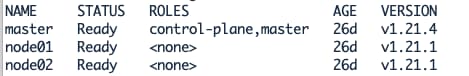
Kubernetes Cluster and versions
Client Version: v3.20.0
Git commit: 38b00edd
Cluster Version: v3.20.0
Cluster Type: k8s,bgp,kubeadm,kdd
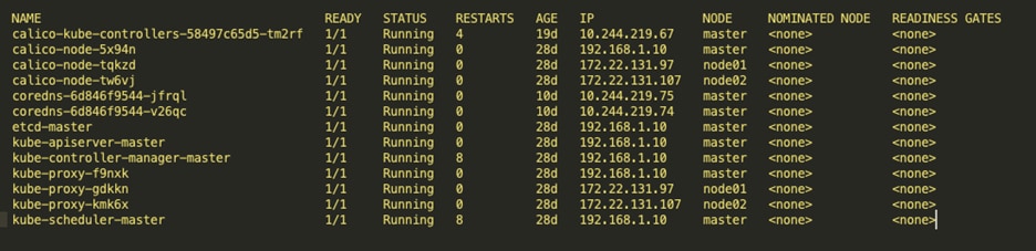
Calico Components
The calico-kube-controller container runs on the master node and the calico-node container runs on all the nodes. The calico-node container is responsible for route programming and route sharing. And calico-kube-controller is for implementing network policies.
The below tables show the Calico-kube-controller and Calico-node running on nodes.
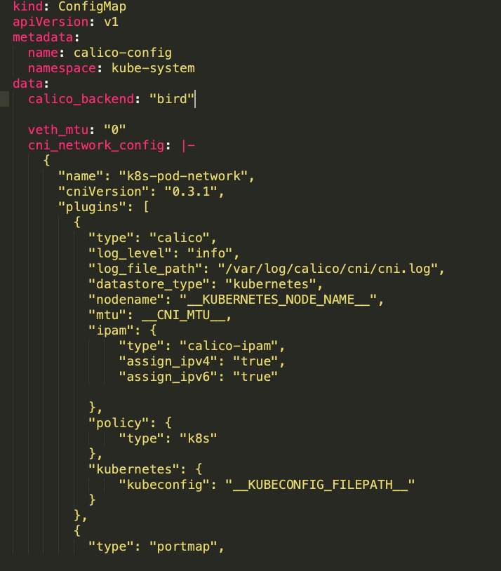
Calico-config
Calico-config is part of calico manifests config. This ConfigMap configures the environment variables such as plugins, datastore, backend and ipam. In our use case we used ipv4 and ipv6 address. ipam : “assign_ipv4” and “assign_ipv6” should be “true” for dual stack. (Please refer to reference section for calico.yaml file details and location)
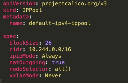
IP in IP configuration
IP-in-IP is a simple form of encapsulation that wraps the packet with an outer IP header that appears as if the source and destination are hosts rather than pods. Therefore, when a host receives an IP-in-IP packet, it examines the internal IP header to determine the target pod.
By default, Calico uses the IP-in-IP mode for routing in order to distribute routes using BGP.
If the ipipMode is set to "Always," it means that all traffic between Calico-managed workloads will be encapsulated in IP-in-IP headers.
To verify that, Check the following in the IPPool manifest.
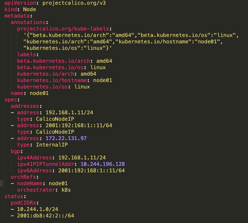
Node-Specific BGP Configuration
In this case study, BGP ipv4 and ipv6 sessions are configured between leafs and Calico nodes. BGP sessions are configured between loopback 1002 address of leafs and connected (bond0) interfaces of Calico nodes. POD IP addresses are allocated from CIDR 10.244.0.0/16. In ipipMode, the POD IP packet is encapsulated in Calico node IP header.
Before configuring BGP, the static routes on all the nodes towards the leaf loopback ip need to be configured.
route add -net 192.168.100.0 netmask 255.255.255.0 gw 192.168.1.1
ip -6 route add 2001:193:168:1::/128 via 2001:192:168:1::1 dev bond0
Below the node configuration uses Calico node IPv4 and IPv6 addresses and POD CIDRs
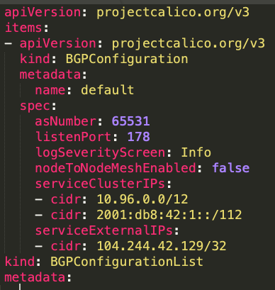
Below BGP configuration list uses BGP AS number, service Cluster IPs and service External IPs.
Below the node BGP Peer configuration uses peer AS number and leaf loopback IP.
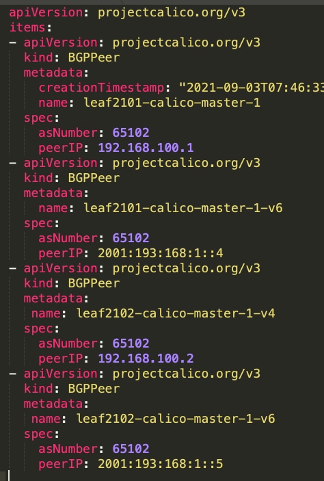
Using calicoctl on master node reveals peering relationship. The cluster peer with loopback address of ToR switch. Below is Calico cluster’s BGP peer table for IPv4 and IPv6
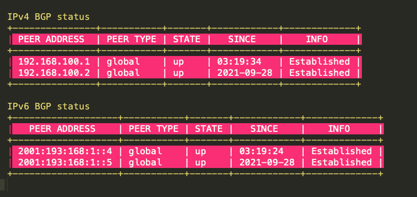
Each peer Address IP represents a ToR switch loopback address and Calico nodes peering with it.
● 192.168.100.1 ToR-1-IPv4 address
● 192.168.100.2. ToR-2-IPv4 address
● 2001:193:168:1::4 ToR-1-IPv6 address
● 2001:193:168:1::5 ToR-2-IPv6 address
Calico Host Routes
The gateway for 12.x.x.x routes received from fabric is the anycast ip address of the fabric. Bond0 is the port-channel interface of the worker node.
The following sample shows the Felix program host’s route table.
root@node1:~# route -n
Kernel IP routing table
Destination Gateway Genmask Flags Metric Ref Use Iface
0.0.0.0 172.22.131.1 0.0.0.0 UG 0 0 0 eno1
1.1.1.1 192.168.1.1 255.255.255.255 UGH 0 0 0 bond0
1.1.1.2 192.168.1.1 255.255.255.255 UGH 0 0 0 bond0
1.1.1.3 192.168.1.1 255.255.255.255 UGH 0 0 0 bond0
1.1.1.4 192.168.1.1 255.255.255.255 UGH 0 0 0 bond0
1.1.1.5 192.168.1.1 255.255.255.255 UGH 0 0 0 bond0
1.1.1.6 192.168.1.1 255.255.255.255 UGH 0 0 0 bond0
10.233.71.0 192.168.1.1 255.255.255.192 UG 0 0 0 bond0
10.233.75.0 192.168.1.1 255.255.255.192 UG 0 0 0 bond0
10.233.102.128 0.0.0.0 255.255.255.192 U 0 0 0 *
10.233.102.129 0.0.0.0 255.255.255.255 UH 0 0 0 cali987b7f71b0c
10.233.102.130 0.0.0.0 255.255.255.255 UH 0 0 0 cali10a39f16907
10.233.102.136 0.0.0.0 255.255.255.255 UH 0 0 0 cali80de97cfe2d
10.233.102.140 0.0.0.0 255.255.255.255 UH 0 0 0 calic3fd4f12902
10.233.102.141 0.0.0.0 255.255.255.255 UH 0 0 0 cali3f71f08da19
12.1.0.0 192.168.1.1 255.255.0.0 UG 0 0 0 bond0
12.2.0.0 192.168.1.1 255.255.0.0 UG 0 0 0 bond0
12.3.0.0 192.168.1.1 255.255.0.0 UG 0 0 0 bond0
12.4.0.0 192.168.1.1 255.255.0.0 UG 0 0 0 bond0
12.5.0.0 192.168.1.1 255.255.0.0 UG 0 0 0 bond0
12.6.0.0 192.168.1.1 255.255.0.0 UG 0 0 0 bond0
12.7.0.0 192.168.1.1 255.255.0.0 UG 0 0 0 bond0
12.8.0.0 192.168.1.1 255.255.0.0 UG 0 0 0 bond0
12.9.0.0 192.168.1.1 255.255.0.0 UG 0 0 0 bond0
12.10.0.0 192.168.1.1 255.255.0.0 UG 0 0 0 bond0
12.11.0.0 192.168.1.1 255.255.0.0 UG 0 0 0 bond0
12.12.0.0 192.168.1.1 255.255.0.0 UG 0 0 0 bond0
12.13.0.0 192.168.1.1 255.255.0.0 UG 0 0 0 bond0
12.14.0.0 192.168.1.1 255.255.0.0 UG 0 0 0 bond0
12.15.0.0 192.168.1.1 255.255.0.0 UG 0 0 0 bond0
12.16.0.0 192.168.1.1 255.255.0.0 UG 0 0 0 bond0
12.17.0.0 192.168.1.1 255.255.0.0 UG 0 0 0 bond0
12.18.0.0 192.168.1.1 255.255.0.0 UG 0 0 0 bond0
12.19.0.0 192.168.1.1 255.255.0.0 UG 0 0 0 bond0
12.20.0.0 192.168.1.1 255.255.0.0 UG 0 0 0 bond0
13.1.0.0 192.168.1.1 255.255.0.0 UG 0 0 0 bond0
13.2.0.0 192.168.1.1 255.255.0.0 UG 0 0 0 bond0
13.3.0.0 192.168.1.1 255.255.0.0 UG 0 0 0 bond0
13.4.0.0 192.168.1.1 255.255.0.0 UG 0 0 0 bond0
13.5.0.0 192.168.1.1 255.255.0.0 UG 0 0 0 bond0
13.6.0.0 192.168.1.1 255.255.0.0 UG 0 0 0 bond0
13.7.0.0 192.168.1.1 255.255.0.0 UG 0 0 0 bond0
13.8.0.0 192.168.1.1 255.255.0.0 UG 0 0 0 bond0
13.9.0.0 192.168.1.1 255.255.0.0 UG 0 0 0 bond0
13.10.0.0 192.168.1.1 255.255.0.0 UG 0 0 0 bond0
13.11.0.0 192.168.1.1 255.255.0.0 UG 0 0 0 bond0
13.12.0.0 192.168.1.1 255.255.0.0 UG 0 0 0 bond0
13.13.0.0 192.168.1.1 255.255.0.0 UG 0 0 0 bond0
13.14.0.0 192.168.1.1 255.255.0.0 UG 0 0 0 bond0
13.15.0.0 192.168.1.1 255.255.0.0 UG 0 0 0 bond0
13.16.0.0 192.168.1.1 255.255.0.0 UG 0 0 0 bond0
13.17.0.0 192.168.1.1 255.255.0.0 UG 0 0 0 bond0
13.18.0.0 192.168.1.1 255.255.0.0 UG 0 0 0 bond0
13.19.0.0 192.168.1.1 255.255.0.0 UG 0 0 0 bond0
13.20.0.0 192.168.1.1 255.255.0.0 UG 0 0 0 bond0
14.1.0.0 192.168.1.1 255.255.0.0 UG 0 0 0 bond0
14.2.0.0 192.168.1.1 255.255.0.0 UG 0 0 0 bond0
14.3.0.0 192.168.1.1 255.255.0.0 UG 0 0 0 bond0
14.4.0.0 192.168.1.1 255.255.0.0 UG 0 0 0 bond0
14.5.0.0 192.168.1.1 255.255.0.0 UG 0 0 0 bond0
14.6.0.0 192.168.1.1 255.255.0.0 UG 0 0 0 bond0
14.7.0.0 192.168.1.1 255.255.0.0 UG 0 0 0 bond0
14.8.0.0 192.168.1.1 255.255.0.0 UG 0 0 0 bond0
14.9.0.0 192.168.1.1 255.255.0.0 UG 0 0 0 bond0
14.10.0.0 192.168.1.1 255.255.0.0 UG 0 0 0 bond0
14.11.0.0 192.168.1.1 255.255.0.0 UG 0 0 0 bond0
14.12.0.0 192.168.1.1 255.255.0.0 UG 0 0 0 bond0
14.13.0.0 192.168.1.1 255.255.0.0 UG 0 0 0 bond0
14.14.0.0 192.168.1.1 255.255.0.0 UG 0 0 0 bond0
14.15.0.0 192.168.1.1 255.255.0.0 UG 0 0 0 bond0
14.16.0.0 192.168.1.1 255.255.0.0 UG 0 0 0 bond0
14.17.0.0 192.168.1.1 255.255.0.0 UG 0 0 0 bond0
14.18.0.0 192.168.1.1 255.255.0.0 UG 0 0 0 bond0
14.19.0.0 192.168.1.1 255.255.0.0 UG 0 0 0 bond0
14.20.0.0 192.168.1.1 255.255.0.0 UG 0 0 0 bond0
172.22.131.0 0.0.0.0 255.255.255.0 U 0 0 0 eno1
192.168.1.0 0.0.0.0 255.255.255.0 U 0 0 0 bond0
192.168.100.0 192.168.1.1 255.255.255.0 UG 0 0 0 bond0
199.101.101.101 192.168.1.1 255.255.255.255 UGH 0 0 0 bond0
199.101.101.102 192.168.1.1 255.255.255.255 UGH 0 0 0 bond0
200.200.200.200 192.168.1.1 255.255.255.255 UGH 0 0 0 bond0
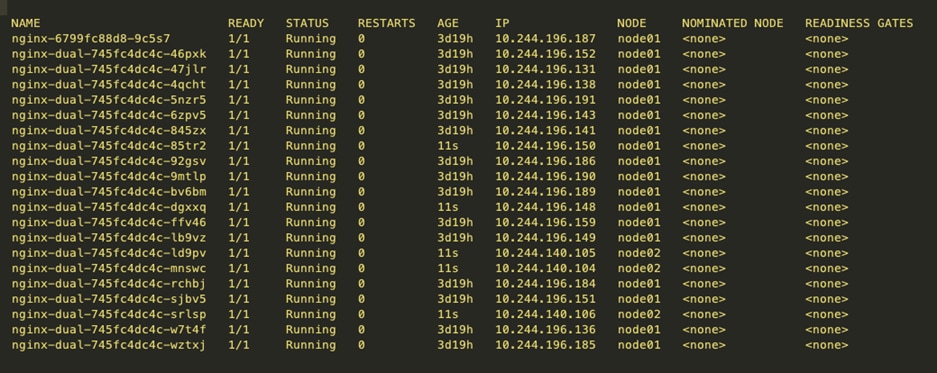
PODs are running on Calico Nodes.
Below table shows multiple nginx containers run in the nodes. Each pod ip address is allocated from the POD CIDRs
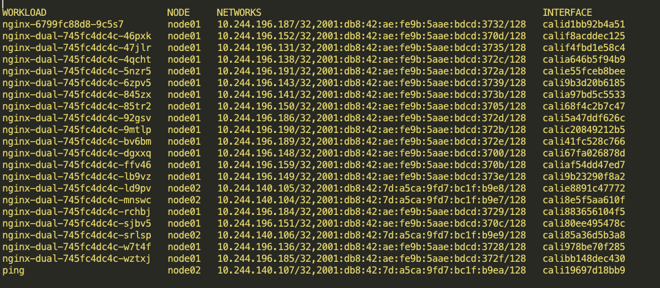
Following table shows the nginx containers hosted on nodes, ipv4/ipv6 address assigned to pods, and the calico network interface.
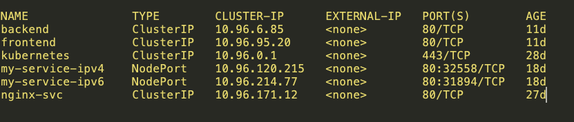
Routable Service Networks
By adding the service CIDRs to the Calico BGP configuration and configuring the ClusterIPs to be associated with Service networks, Calico will advertise these addresses to the fabric.
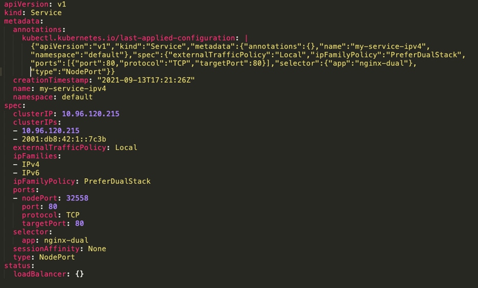
The below table shows ClusterIP and NodePort Services.
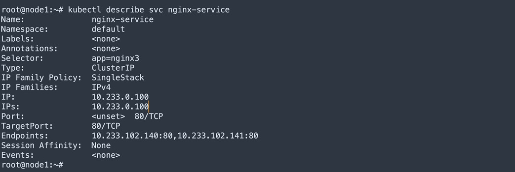
The following diagram shows ClusterIP service metadata.
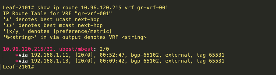
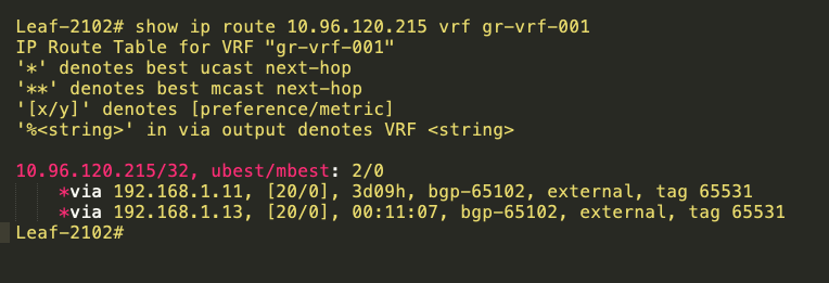
The below tables are NodePort ClusterIP routes at the leaf.
10.96.120.215 is NodePort ClusterIP, 192.168.1.11 and 192.168.1.13 are loopback IPs of Calico Nodes.
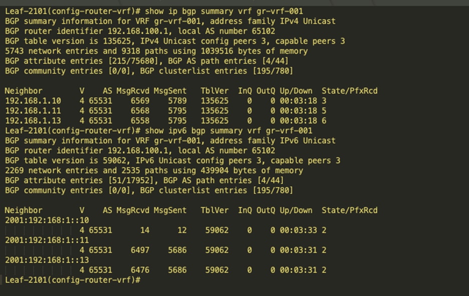
BGP IPv4 and v6 neighbor between leaf and the Calico Nodes
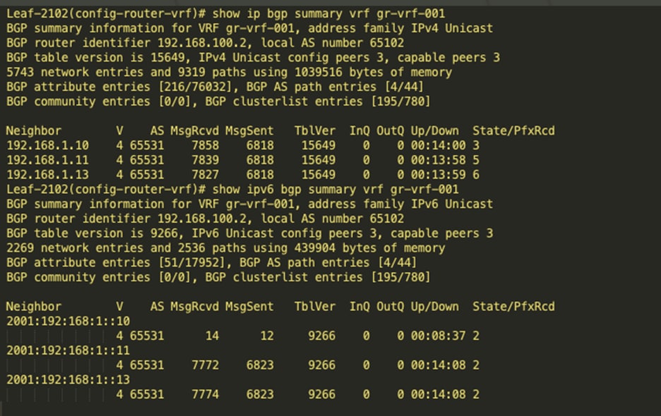
Anycast Gateway config at Leaf
BGP Config at Leaf
router bgp 65102
router-id 10.2.1.1
address-family ipv4 unicast
network 0.0.0.0/0
network 192.168.100.2/32
redistribute direct route-map fabric-rmap-redist-subnet
maximum-paths ibgp 2
address-family ipv6 unicast
redistribute direct route-map fabric-rmap-redist-subnet
maximum-paths ibgp 2
address-family l2vpn evpn
advertise-pip
template peer K8
remote-as 65531
update-source loopback1002
ebgp-multihop 10
address-family ipv4 unicast
route-map calico-ip-filter out
template peer K8-v6
remote-as 65531
update-source loopback1002
ebgp-multihop 10
address-family ipv6 unicast
route-map calico-ipv6-filter out
neighbor 10.2.1.5
remote-as 65102
password 3 8fefa6b7668dc51d3ddc35f4e99cc574
update-source loopback0
address-family l2vpn evpn
send-community
send-community extended
neighbor 10.2.1.6
remote-as 65102
password 3 8fefa6b7668dc51d3ddc35f4e99cc574
update-source loopback0
address-family l2vpn evpn
send-community
send-community extended
vrf gr-vrf-001
address-family ipv4 unicast
network 0.0.0.0/0
network 192.168.100.2/32 route-map set_rt
advertise l2vpn evpn
redistribute direct route-map fabric-rmap-redist-subnet
aggregate-address 90.8.0.0/16 summary-only
maximum-paths 64
maximum-paths ibgp 2
address-family ipv6 unicast
network ::/0
network 2001:193:168:1::5/128
advertise l2vpn evpn
redistribute direct route-map fabric-rmap-redist-subnet
maximum-paths ibgp 2
neighbor 2001:192:168:1::11
inherit peer K8-v6
neighbor 2001:192:168:1::13
inherit peer K8-v6
neighbor 2001:192:168:1:28b6:92ff:fefc:7978
inherit peer K8-v6
neighbor 192.168.1.10
inherit peer K8
address-family ipv4 unicast
as-override
disable-peer-as-check
neighbor 192.168.1.11
inherit peer K8
address-family ipv4 unicast
as-override
disable-peer-as-check
neighbor 192.168.1.13
inherit peer K8
address-family ipv4 unicast
as-override
disable-peer-as-check
Use case of Calico ipipMode
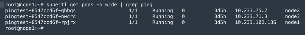
Pingtest POD deployed at node1, node2 and node3. POD pingtest-8547ccd6f-rpjrx at node1, ping the POD pingtest-8547ccd6f-ghbqs @ node2. Capture the packet at node1 bond0 interface and as well as @ Leaf port-channel interface.
Pingtest PODs deployed at Nodes
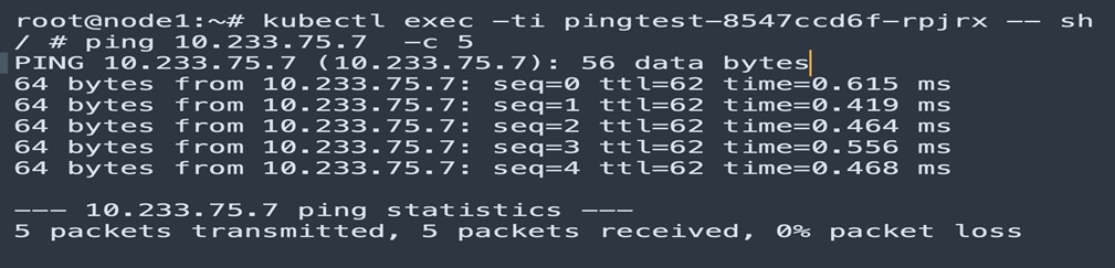
Ping from Node1 pingtest POD to Node2 pingtest POD.
Packet capture in the Calico Node is shown below:
● Outer source IP address 192.168.1.10 is bond0 address of Node1
● Outer DST IP address 192.168.1.11 is bond0 address of Node2
● Inner source IP address 10.233.102.136 of POD pingtest-8547ccd6f-ghbqs
● Inner DST IP address 10.233.75.7 of POD pingtest-8547ccd6f-rpjrx
● encapsulation IPIP
● protocol icmp
Ethernet II, Src: fe:f8:86:b8:5f:7e (fe:f8:86:b8:5f:7e), Dst: 32:73:87:0b:5f:3f (32:73:87:0b:5f:3f)
Destination: 32:73:87:0b:5f:3f (32:73:87:0b:5f:3f)
Address: 32:73:87:0b:5f:3f (32:73:87:0b:5f:3f)
Source: fe:f8:86:b8:5f:7e (fe:f8:86:b8:5f:7e)
Address: fe:f8:86:b8:5f:7e (fe:f8:86:b8:5f:7e)
Type: IPv4 (0x0800)
Internet Protocol Version 4, Src: 192.168.1.10, Dst: 192.168.1.11
Differentiated Services Field: 0x00 (DSCP: CS0, ECN: Not-ECT)
Protocol: IPIP (4)
Source: 192.168.1.10
Destination: 192.168.1.11
Internet Protocol Version 4, Src: 10.233.102.136, Dst: 10.233.75.7
Differentiated Services Field: 0x00 (DSCP: CS0, ECN: Not-ECT)
Protocol: ICMP (1)
Source: 10.233.102.136
Destination: 10.233.75.7
Internet Control Message Protocol
Type: 8 (Echo (ping) request)
Packet capture in the VxLAN fabric is shown below:
● Outer source IP address 192.168.1.11 is bond0 address of Node2
● Outer DST IP address 192.168.1.10 is bond0 address of Node1
● Inner source IP address 10.233.75.7 of POD pingtest-8547ccd6f-ghbqs
● Inner DST IP address 10.233.102.136 of POD pingtest-8547ccd6f-rpjrx
● encapsulation IPIP
● protocol icmp
Ethernet II, Src: 32:73:87:0b:5f:3f, Dst: fe:f8:86:b8:5f:7e
Destination: fe:f8:86:b8:5f:7e
Address: fe:f8:86:b8:5f:7e
Source: 32:73:87:0b:5f:3f
Address: 32:73:87:0b:5f:3f
Type: 802.1Q Virtual LAN (0x8100)
802.1Q Virtual LAN, PRI: 0, DEI: 0, ID: 0
Type: IPv4 (0x0800)
Internet Protocol Version 4, Src: 192.168.1.11, Dst: 192.168.1.10
Differentiated Services Field: 0x00 (DSCP: CS0, ECN: Not-ECT)
Protocol: IPIP (4)
Source: 192.168.1.11
Destination: 192.168.1.10
Internet Protocol Version 4, Src: 10.233.75.7, Dst: 10.233.102.136
Differentiated Services Field: 0x00 (DSCP: CS0, ECN: Not-ECT)
Protocol: ICMP (1)
Source: 10.233.75.7
Destination: 10.233.102.136
Internet Control Message Protocol
Type: 0 (Echo (ping) reply)
Use case of Service ClusterIP
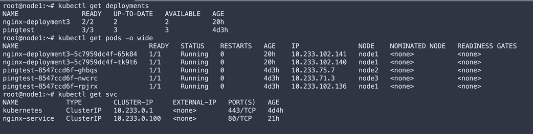
Below table shows the nginx-deployment2 deployed PODs at node1. Service object nginx-service is created. Service ClusterIP 10.233.0.100 mapped to 10.233.102.141 and 10.233.102.140 endpoints.
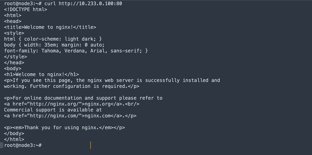
Below figure shows the executed curl for Service clusterIP from node3 and corresponding nginx pods are deployed at node1.
Packet capture in the VxLAN fabric is shown below:
● Source IP address 192.168.1.13 is bond0 address of Node2
● DST IP address 10.233.102.141 is POD IP
● protocol http
Ethernet II, Src: 6c:31:0e:b3:7c:47, Dst: fe:f8:86:b8:5f:7e
Destination: fe:f8:86:b8:5f:7e
Address: fe:f8:86:b8:5f:7e
Source: 6c:31:0e:b3:7c:47
Address: 6c:31:0e:b3:7c:47
Type: 802.1Q Virtual LAN (0x8100)
802.1Q Virtual LAN, PRI: 0, DEI: 0, ID: 3001
Type: IPv4 (0x0800)
Internet Protocol Version 4, Src: 192.168.1.13, Dst: 10.233.102.141
Differentiated Services Field: 0x00 (DSCP: CS0, ECN: Not-ECT)
Protocol: TCP (6)
Source: 192.168.1.13
Destination: 10.233.102.141
Transmission Control Protocol, Src Port: 22996, Dst Port: 80, Seq: 1, Ack: 1, Len: 76
Source Port: 22996
Destination Port: 80
Hypertext Transfer Protocol
GET / HTTP/1.1\r\n
Host: 10.233.0.100\r\n
[Full request URI: http://10.233.0.100/]
[HTTP request 1/1]
Conclusion
Cisco NX-OS and Calico with eBGP provide a robust solution for connecting a VxLAN fabric with a scalable, multi-host networking and network policy implementation. This solution allows for flexible network configurations, improved network visibility, and efficient network traffic management. However, proper implementation and configuration of eBGP, VxLAN, and Calico are crucial for ensuring optimal performance and reliability.
Reference
https://docs.projectcalico.org/getting-started/kubernetes/quickstart
https://docs.projectcalico.org/networking/bgp
https://www.tigera.io/blog/advertising-kubernetes-service-ips-with-calico-and-bgp/
https://www.cisco.com/c/en/us/td/docs/dcn/whitepapers/cisco-nx-os-calico-network-design.html
https://kubernetes.io/docs/setup/production-environment/tools/kubeadm/install-kubeadm/
https://github.com/projectcalico/calico/blob/master/manifests/calico.yaml
Legal Information
Cisco and the Cisco logo are trademarks or registered trademarks of Cisco and/or its affiliates in the U.S. and other countries. To view a list of Cisco trademarks, go to this URL: www.cisco.com/go/trademarks. Third-party trademarks mentioned are the property of their respective owners. The use of the word partner does not imply a partnership relationship between Cisco and any other company. (1110R)
Any Internet Protocol (IP) addresses and phone numbers used in this document are not intended to be actual addresses and phone numbers. Any examples, command display output, network topology diagrams, and other figures included in the document are shown for illustrative purposes only. Any use of actual IP addresses or phone numbers in illustrative content is unintentional and coincidental.