Cisco NX-OS Calico Network Design White Paper
Available Languages
Bias-Free Language
The documentation set for this product strives to use bias-free language. For the purposes of this documentation set, bias-free is defined as language that does not imply discrimination based on age, disability, gender, racial identity, ethnic identity, sexual orientation, socioeconomic status, and intersectionality. Exceptions may be present in the documentation due to language that is hardcoded in the user interfaces of the product software, language used based on RFP documentation, or language that is used by a referenced third-party product. Learn more about how Cisco is using Inclusive Language.
- US/Canada 800-553-2447
- Worldwide Support Phone Numbers
- All Tools
 Feedback
 Feedback
This document assumes the reader is familiar with the basic concepts of Kubernetes and Calico and has an existing fabric running using either eBGP-based IP fabric or VXLAN EVPN-based fabric. This document mainly focuses on design considerations with examples of the configuration of related components.
Kubernetes is one of the most popular container orchestrators (usually abbreviated as K8s) when users deploy applications on container platforms. It provides network functions like connectivity of pod and service network, IP address management and security policies via a CNI (Container Network Interface) plugin. Depending on the CNI chosen by the customer, requirements at the underlay network can be different. Calico is one of the favorite CNI plugins available for users to build their own Kubernetes cluster on-prem. Multiple options are available in Calico, however the most popular one is using non-overlay mode and leveraging the physical network to exchange routing information of Kubernetes nodes with Border Gateway Protocol (BGP).
This white paper’s aim is to provide guidance about the options of designing the network and best practices with Cisco Nexus platform to support Kubernetes and Calico.
Note: The documentation set for this product strives to use bias-free language. For the purposes of this documentation set, bias-free is defined as language that does not imply discrimination based on age, disability, gender, racial identity, ethnic identity, sexual orientation, socioeconomic status, and intersectionality. Exceptions may be present in the documentation due to language that is hardcoded in the user interfaces of the product software, language used based on RFP documentation, or language that is used by a referenced third-party product.
Project Calico[1] is an open-source network and network security solution for containers, virtual machines, and native host-based workloads. In this document, when referring to Calico, we are only using it as a CNI plugin of Kubernetes.
Calico provides two main network options:
● The non-overlay mode using Border Gateway Protocol (BGP) peering between all Kubernetes nodes and the physical network (typically a BGP-capable switch usually is referred as Top-of-Rack switch or ToR).
● The overlay network mode where traffic between K8s nodes is encapsulated in VXLAN or another layer of IP (IP-in-IP).
The most common network setup to run Calico on-premises is non-overlay mode, in this mode, the routing control plane is provided by a BGP daemon (BIRD[2]) running on every Kubernetes node. When deploying Calico in non-overlay mode, users can choose to run full-mesh to peer all Kubernetes nodes with each other using iBGP, or for better scale use a Route-Reflector (RR) design. In this mode, the traffic across nodes is transparent to the underlying ToR switches, which provide IP reachability between K8s nodes. In the non-overlay mode, the ToR switches usually act as RR for the connected Kubernetes nodes. In the case of overlay mode, as all the intra-cluster traffic is encapsulated in either VXLAN or IP-in-IP, the underlay physical network is not aware of the workload’s IP addresses and only provides IP reachability to the Kubernetes nodes.
Comparing these two modes discussed above, running overlay mode has a significant drawback as the underlay network will not be able to detect the IP addresses of workloads. When deploying Calico on-premises, it is suggested by Calico to use the non-overlay mode[3] and peer BGP on the K8s nodes with the physical network (called ToR switches). Cisco NX-OS provides flexibility to integrate with Calico Network from small size to hyper-scale Kubernetes cluster. This document only focuses on the recommended configuration of Cisco NX-OS when deploying Calico over two typical fabrics--IP fabric and VXLAN EVPN fabric when using non-overlay mode.
Before diving into network design, let us look at the network architecture of a typical Calico deployment. This white paper explains it from a networking perspective, to provide a better understanding of the Calico network architecture components.
Calico uses the network stack of the Linux kernel as data plane Kubernetes nodes with the Calico CNI plugin behaving just like any router. RIB (Routing Information Base) is responsible for programming FIB (Forwarding Information Base) while BGP takes care of routing information exchanges with other routers. The Calico CNI plugin is combined with different components and depending on requirements, not all components are necessary. In this white paper, we will briefly introduce the two main components that are relevant for network design. Other component details can be found in [4].
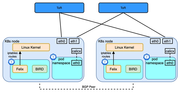
Figure 1
Calico Network Architecture
● Felix: programs routes and ACLs (iptables) and anything required on Calico node to provide connectivity for the pods scheduled on that node
● BIRD: it is a routing daemon running in the same pod as Felix, responsible for peering with other K8s nodes and exchanging routes of pod network and service network for inter-node communication.
Each Calico node has one node IP, one or more ranges of IP addresses (CIDRs) for pod networks and a shared network for the whole Kubernetes cluster which is called service network. To simplify the network architecture of Calico, each node is acting as a virtual router, one or two interfaces are used to connect to uplink switches (ToR) and the virtual router itself. The virtual router is also the gateway for one or more pod networks. Then Figure 1 can be simplified as shown below:
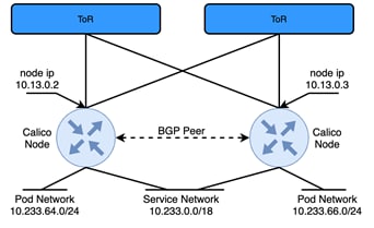
Figure 2
Simplified Calico Network Architecture
In Figure 2 two Calico nodes are peering each other with BGP, this design is also referred as full-mesh: all calico nodes establish iBGP neighbor relations with all other nodes to exchange the pod network that’s been allocated to each node. Each node also advertises the subnet used for Kubernetes Services. For better scale, especially when ToR switches are BGP capable, Calico suggests using Router-Reflectors (RR)[4]. One or more Calico nodes can be used as RR, but a more common design is to use the directly connected ToR switch as a RR. When using a ToR switch as a RR, there are several design considerations:
● AS per rack, all Calico nodes within the rack share the same AS number; depending on the type of fabric (IP Fabric or VXLAN EVPN fabric), all Calico nodes in the same rack become BGP neighbors with the ToR switches in the same rack.
● AS per compute server, where a different AS number is used by each Calico Node. The AS number is also different from the AS used by the fabric, meaning Calico nodes peers with ToR switches using eBGP in each rack.
● Downward Default: instead of learning all the node networks from each node, in this model the uplink ToR switch only advertises a default route to Calico Nodes to minimize the hosts’ routing table.
If all the workloads of a given fabric are running on one or more Kubernetes clusters, most of the time an overlay is not needed as the segmentation is done within Kubernetes using networking policies. In this case an IP Fabric is the preferred method to host Kubernetes workload. In this model, Calico recommends using AS-per-Rack mode[5], which is also the model we recommend when deploying Kubernetes clusters exclusively in an IP Fabric. However, the same fabric could also carry other workloads like virtual machines or bare metal servers or multiple Kubernetes clusters with overlapping addresses could connect to the same fabric. In such cases, an overlay like VXLAN EVPN is needed to isolate the clusters or provide L2 extension for non-Kubernetes workloads. This white paper will also discuss some of the options when deploying Kubernetes cluster over VXLAN EVPN fabrics.
The most popular and scalable design is called Layer 3 IP Fabric which is a common design in Massively Scalable Data Centers (MSDC) and extensively described in RFC 7938 - Use of BGP for Routing in Large-Scale Data Centers[7]. The sections that follow will discuss what is the best practice to deploy Calico network in eBGP based IP fabric.
Connect Calico Node to IP Fabric
If using bare-metal servers for Kubernetes nodes, those can connect to ToR switches with either single-homed or dual-home schemes. Single-homed designs are simpler, they require more high availability from the application layer which usually is not a big issue in Kubernetes environments. In K8s, the scheduler can create new replicas of nodes that are failing. However, losing one ToR switch could mean hundreds of pods get disconnected from the network, with a risk of losing all the replicas of a Deployment and leading to longer service recovery time. Thus, using virtual Port-Channel (vPC) is a good way to provide better redundancy from the underlay network.
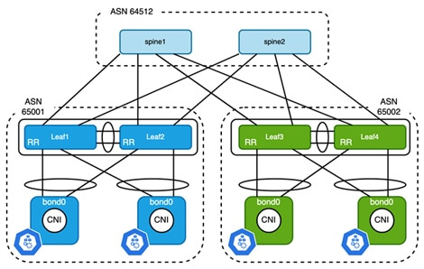
Figure 3
Connect Kubernetes Node to ToR Switches Using vPC
The topology above gives an example of how to connect bare-metal Kubernetes nodes to ToR switches. To create a bonding interface on a Kubernetes node, the best practice is using 802.3ad or mode 4 of bonding[8] to avoid mis-cabling and better L2 convergence. While on the switch side, two ToR switches are configured as vPC peer. The node IP of Kubernetes nodes is configured on bond interfaces. The corresponding Port-Channel on ToR switches is configured as access port with a Switch Virtual Interface (SVI) configured for each pair of vPC switches to provide default gateway services for the Kubernetes nodes. HSRP and VRRP can be used for gateway redundancy, which operates in Active/Active in conjunction with vPC. Since there is no overlay in the case of IP fabric designs, the VLAN used between ToR and Kubernetes nodes can be the same on all switches, however the subnet must be unique. Here is the summary of resource allocations of Figure 3:
Table 1. Example of Resource Allocation
| Rack Number |
ASN |
VLAN |
Node Subnet |
| Rack 1 |
65001 |
2300 |
10.13.0.0/24 |
| Rack 2 |
65002 |
2300 |
10.14.0.0/24 |
Similarly, when deploying Kubernetes nodes in Virtual Machines (VM), the only difference is that NIC teaming is configured at virtual switch of the virtual machine hypervisor instead of the node itself. Care must be given to VM placement, since the node subnet on each rack is different, a VM needs to stick to hosts that connect to same ToR switches. For example, in vSphere, VM/Host affinity rules can be used to achieve that.
Network Design Consideration
As shown in Figure 3, two ToR switches and all Kubernetes nodes are in the same AS (Autonomous System). Each Kubernetes node establishes two iBGP connections, one to each ToR switch. Calico enables full-mesh BGP peers among all the Kubernetes nodes by default. To peer with a ToR switch, that full-mesh configuration knob must be disabled first. Also, since a ToR switch establishes iBGP peers with all K8s nodes, it is required to configure the ToR switches as route-reflector in order to advertise the pod subnet to Kubernetes nodes in the same rack.
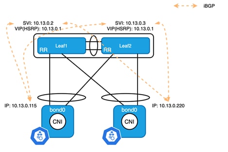
Figure 4
iBGP Connection between Kubernetes Nodes and ToR Switches
Zooming in on each rack, HSRP or VRRP is used for gateway redundancy, however, the VIP cannot be used for routing protocol peering. When configuring the BGP peer on a Kubernetes node, you select the primary IP address of the SVI to peer with each ToR switch. The node subnet on each ToR switch must be either redistributed to BGP in the unicast address family or directly advertised to BGP using a network statement to provide reachability between nodes on different racks.
Next-Hop Behavior
Since Kubernetes nodes in the same rack all belong to the same AS, when a ToR switch reflects the pod networks, learned between nodes in the same rack, with the next hop as the node IP of the source Kubernetes node. As all nodes in the same rack are connected in the same VLAN/Subnet, the next-hop is always reachable and next-hop-self is not needed for the communication within a ToR switch.
Routes advertised from Kubernetes nodes residing in remote racks are different. ToR switches establish eBGP neighbor with spine switches, and by default next hop of routes learned from eBGP neighbors should be carried over to iBGP neighbors. This means that when Kubernetes nodes receive routes that originated from other racks, the next hop will be the IP address of the spine switches (usually it is the IP address of the interface that connects to the ToR switch). Per RFC 4271, when a router receives a BGP path, recursive lookup should be performed to resolve the immediate next hop. If the default gateway of the Kubernetes node is pointing to the SVI on the ToR switch, it will be resolved to the VIP of HSRP which is the expected behavior; nothing needs to be changed on the physical network. However, if the node is connected to different networks, for example when the user wants to use a separate network for management, the default route could point to a different network; the immediate next hop will be resolved to the wrong address. To overcome this, the next hop-self feature can be used to override the next hop of the path received from spine switches to the ToR itself.
ECMP Load Balancing
Another design consideration is ECMP load balancing. The pod network advertised from a given Kubernetes node is unique and only originates from a single node. However, as a node is connected to two ToR switches, both switches will advertise the same path to neighbor spines. By default, a spine will only install first learned into the RIB (Routing Information Base). This means only one path is used for cross fabric traffic. The maximum-paths knob must be configured on all spine switches to create ECMP between leaf switches, which is not just best practice for container workloads but for IP fabrics in general.
Kubernetes workloads seldom use individual pods directly, micro services hosted in pods are usually exposed using Services[9] in Kubernetes. As shown in Figure 2, the Service network is shared across the Kubernetes cluster. If the Service is created with type of ClusterIP, the /32 or /128 service IP is not advertised by Kubernetes nodes, only the entire Service network is statically advertised by all Kubernetes nodes. That means the fabric receives the same path from different originators. While all paths will eventually be advertised to the spines, the AS paths are different. In this case maximum-paths by itself will not add all available paths to the RIB as it requires identical AS paths. Configuring bestpath as-path multipath-relax allows spines to load-balance across different ToR switches with different AS paths. At the time of writing, Cisco Nexus switch supports up to 64-way ECMP which usually is enough for most situations.
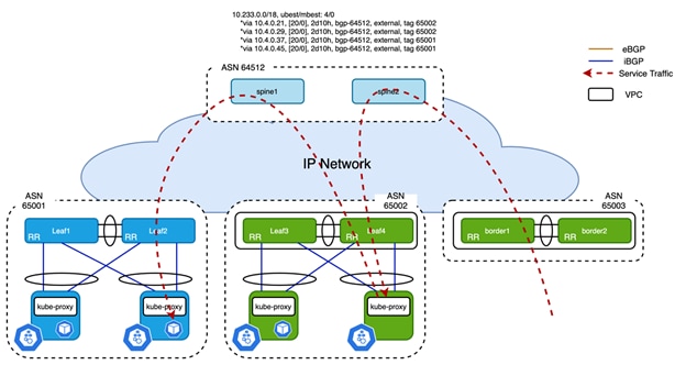
Figure 5
Second Hop of Service Traffic when ExternalTrafficPolicy is Cluster
As shown in Figure 5, external traffic is forwarded to any node even when there is no backing pod available on that node. Even in the presence of traffic tromboning, good overall load balancing is achieved. If you want to avoid this potential sub-optimal forwarding path, Calico also respects the externalTrafficPolicy of Kubernetes Service spec. If externalTrafficPolicy is Cluster which is the default, the traffic will be handled as mentioned above. When externalTrafficPolicy is Local, only the node that has the pod backing this service will advertise the /32 service IP to upstream ToR switches. However, it only applies to Service types NodePort and LoadBalancer.
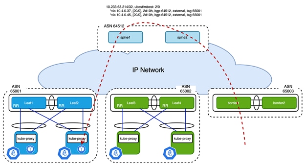
Figure 6
Service Traffic Forwarded to ToR Based on /32 Service Route when externalTrafficPolicy is Local
This white paper only focuses on Calico network design, the differences between Kubernetes Service types can be found in [9].
Cisco NX-OS and Calico Configuration
Example of Cisco NX-OS Configuration
Below is an example of the configuration on ToR switches:
router bgp 65001
router-id 10.2.0.3
address-family ipv4 unicast
maximum-paths 4
maximum-paths ibgp 16
neighbor 10.13.0.0/24
remote-as 65001
update-source Vlan2300
address-family ipv4 unicast
route-reflector-client
Example 2 BGP Configuration of ToR Switch
The neighbor configuration for each Kubernetes node is the same; users can create a peer template and inherit from it but still needs to peer each individual node that gets added to the cluster. Cisco NX-OS supports prefix peering with an entire subnet which can significantly reduce configuration complexity. The source interface Vlan2300 is the gateway of the Kubernetes node network. As mentioned in section “ECMP Load Balancing”, maximum-paths ibgp needs to be configured in order to share the load between nodes in the same rack for the service network.
While on the spines, make sure the configuration below is present to properly load balance service traffic:
router bgp 64512
bestpath as-path multipath-relax
Example 3 Multipath-relax Configuration of Spine Switches
Example of Calico Configuration
To peer with a switch, nodeToNodeMeshEnabled of BGPConfiguration must be set to false first:
# calicoctl get bgpConfig -o yaml
apiVersion: projectcalico.org/v3
items:
- apiVersion: projectcalico.org/v3
kind: BGPConfiguration
metadata:
creationTimestamp: "2021-06-29T19:14:56Z"
name: default
resourceVersion: "831"
uid: 17eb28fc-feb9-4c01-bc5d-e768f483166e
spec:
listenPort: 179
logSeverityScreen: Info
nodeToNodeMeshEnabled: false
serviceClusterIPs:
- cidr: 10.233.0.0/18
kind: BGPConfigurationList
metadata:
resourceVersion: "443603"
Example 4 Disable Node to Node Full Mesh of Calico
At least one IP Pool must be configured for the node subnet, ipipMode and vxlanMode must be set to Never as no overlay is required when peering the Calico nodes to ToR switches:
# calicoctl get ipPool -o yaml
apiVersion: projectcalico.org/v3
items:
- apiVersion: projectcalico.org/v3
kind: IPPool
metadata:
creationTimestamp: "2021-06-29T19:14:56Z"
name: default-pool
resourceVersion: "830"
uid: c732a148-e563-4ba9-b6dc-80bfdc414332
spec:
blockSize: 24
cidr: 10.233.64.0/20
ipipMode: Never
nodeSelector: all()
vxlanMode: Never
kind: IPPoolList
metadata:
resourceVersion: "443648"
Example 5 Disable ipipMode and vxlanMode of ip Pool
Use the command below to configure asNumber of a particular Kubernetes node, the same configuration must be repeated on each node:
# calicoctl patch node lab105-k8s-node0 -p '{"spec": {"bgp": {"asNumber": "65001"}}}'
Example 6 Configure AS Number of One Calico Node
Create two bgpPeer resources on each Calico node to peer with ToR switches:
# cat bgp_peer_master.yml
---
apiVersion: projectcalico.org/v3
kind: BGPPeer
metadata:
name: lab105-k8s-master-10.13.0.2
spec:
asNumber: 65001
node: lab105-k8s-master
peerIP: 10.13.0.2
---
apiVersion: projectcalico.org/v3
kind: BGPPeer
metadata:
name: lab105-k8s-master-10.13.0.3
spec:
asNumber: 65001
node: lab105-k8s-master
peerIP: 10.13.0.3
Example 7 bgpPeer Configuration of One Calico Node
In the above example, peerIP is the primary IP address of the SVI on each ToR switch of vPC pair. Apply it use below command:
# calicoctl apply -f bgp_peer_master.yml
Example 8 Apply bgp peer Configuration to Calico
As the BGP peer configuration of nodes in the same rack are exactly the same as in the AS-per-Rack design, Example 7 can be modified as shown below to apply the same configuration to nodes with the same label:
# cat bgp_peer_rack_bb1.yaml
---
apiVersion: projectcalico.org/v3
kind: BGPPeer
metadata:
name: rack-bb1-leaf1
spec:
peerIP: 10.13.0.2
asNumber: 65001
nodeSelector: rack=='bb1'
---
apiVersion: projectcalico.org/v3
kind: BGPPeer
metadata:
name: rack-bb1-leaf2
spec:
peerIP: 10.13.0.3
asNumber: 65001
nodeSelector: rack=='bb1'
Example 9 Use of Label to Configure BGP Peers in Same Rack
Once bgpPeer is configured on a Calico node, the neighbor should be established between Calico and the directly connected switch. The output below is the node status on Kubernetes node:
# calicoctl node status
Calico process is running.
IPv4 BGP status
+--------------+---------------+-------+------------+-------------+
| PEER ADDRESS | PEER TYPE | STATE | SINCE | INFO |
+--------------+---------------+-------+------------+-------------+
| 10.13.0.2 | node specific | up | 2021-06-29 | Established |
| 10.13.0.3 | node specific | up | 2021-06-29 | Established |
+--------------+---------------+-------+------------+-------------+
IPv6 BGP status
No IPv6 peers found.
Example 10 BGP Status of Calico Node
The output below is from the ToR switch to show the routes learned from Calico nodes:
leaf1# show ip route bgp
IP Route Table for VRF "default"
'*' denotes best ucast next-hop
'**' denotes best mcast next-hop
'[x/y]' denotes [preference/metric]
'%<string>' in via output denotes VRF <string>
< omitted >
10.233.0.0/18, ubest/mbest: 3/0 <<<< service subnet
*via 10.13.0.115, [200/0], 01:27:28, bgp-65001, internal, tag 65001
*via 10.13.0.181, [200/0], 01:27:28, bgp-65001, internal, tag 65001
*via 10.13.0.220, [200/0], 01:27:28, bgp-65001, internal, tag 65001
10.233.50.6/32, ubest/mbest: 2/0 <<<< service IP
*via 10.13.0.115, [200/0], 01:27:28, bgp-65001, internal, tag 65001
*via 10.13.0.220, [200/0], 01:27:28, bgp-65001, internal, tag 65001
10.233.63.214/32, ubest/mbest: 2/0
*via 10.13.0.115, [200/0], 01:27:28, bgp-65001, internal, tag 65001
*via 10.13.0.220, [200/0], 01:27:28, bgp-65001, internal, tag 65001
10.233.65.0/24, ubest/mbest: 1/0 <<<< pod subnet from local node
*via 10.13.0.115, [200/0], 01:27:28, bgp-65001, internal, tag 65001
10.233.73.0/24, ubest/mbest: 2/0 <<<< pod subnet from remote node
*via 10.4.0.34, [20/0], 01:27:28, bgp-65001, external, tag 64512
*via 10.4.0.38, [20/0], 01:27:28, bgp-65001, external, tag 64512
10.233.77.0/24, ubest/mbest: 1/0
*via 10.13.0.220, [200/0], 01:27:28, bgp-65001, internal, tag 65001
10.233.79.0/24, ubest/mbest: 1/0
*via 10.13.0.181, [200/0], 01:27:28, bgp-65001, internal, tag 65001
Example 11 Routes Learned from ToR Switch
The Service subnet is load balanced between the Kubernetes nodes directly connected to this switch. The pod subnet is unique among the nodes, and the one learned from local node originates from only one node. The one learned from nodes connected to different racks is load balanced between spines. Service traffic must be load balanced correctly on spine switches among all the ToR switches:
spine1# show ip route 10.233.0.0/18
IP Route Table for VRF "default"
'*' denotes best ucast next-hop
'**' denotes best mcast next-hop
'[x/y]' denotes [preference/metric]
'%<string>' in via output denotes VRF <string>
10.233.0.0/18, ubest/mbest: 4/0
*via 10.4.0.21, [20/0], 2d12h, bgp-64512, external, tag 65002
*via 10.4.0.29, [20/0], 2d12h, bgp-64512, external, tag 65002
*via 10.4.0.37, [20/0], 2d12h, bgp-64512, external, tag 65001
*via 10.4.0.45, [20/0], 2d12h, bgp-64512, external, tag 65001
Example 12 ECMP of Service Subnet on Spine Switch
Deploy Calico over VXLAN EVPN fabrics
VXLAN EVPN fabric is the most popular solution of overlay network, this section will discuss how to design the Calico network with VXLAN EVPN fabric and which available options are best practices.
Connect Calico Node to VXLAN EVPN Fabric
The physical connection to VXLAN EVPN Fabric is similar to the IP fabric scenario. A best practice consists in using vPC to provide better redundancy. VXLAN routing provides anycast gateway on all leaf switches that connect to Kubernetes nodes, which means a single subnet can be used for node IPs of the entire Kubernetes cluster. Resource allocation is reduced dramatically as only one VLAN/VNI/subnet is needed for all the Kubernetes nodes no matter where they are connected.
Cisco suggests using an IGP like OSPF or IS-IS for underlay network while using iBGP for overlay network in the VXLAN EVPN fabric, details can be found in [10]. Calico provides more flexibility in terms of configuration options. Users can choose between a single AS number for the entire cluster (AS-Per-Cluster) or stick with the AS-per-Rack design option. This white paper will mainly focus on how to connect Calico network to VXLAN EVPN fabric which is using iBGP as overlay, however, it will also explain the design considerations when eBGP is used.
Network Design Consideration
Local Routing Peering
The best practice is always forming BGP neighborship with locally attached leaf switches as that gives the best scalability and redundancy. Unlike the IP fabric case, the SVI on leaf switches are usually configured as anycast gateway, and the same IP address is pervasively extended on all leaf switches. BGP peering with anycast gateway is not supported by Cisco NX-OS as it would fail in the case of vPC; the attached node would only be able to speak to one ToR, which defeats the purpose of redundancy. As a result, a unique loopback address is configured on each leaf switch as source IP address of BGP control plane.
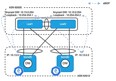
Figure 7
BGP Peering between Leaf Switch to Kubernetes Node
As shown in Figure 7, all leaf switches are in the same AS while all Kubernetes nodes are in another AS. An eBGP session is established between the node IP of each Kubernetes node and the loopback address of the local leaf switch. As the loopback is 2 to 3 hops away from the node IP, ebgp-multihop must be set at least to 3 in order to establish the TCP connection for eBGP. From the leaf switch’s perspective, it connects to two neighbors in the same AS. By default, the path learned by the leaf will not be advertised to any other Kubernetes nodes as ASN 64512 was already prepended last to the AS_PATH attribute list. In this well-controlled topology, disable-peer-as-check must be configured under the unicast address family to uplift the limit of a route being received from its own AS. For the same reason, when a Kubernetes node receives a path from leaf switches, it will be rejected. However, the BGP configuration on Calico is limited and most of the default behavior is not configurable. To overcome this, as-override must be set under unicast address family of neighbor on leaf switches.
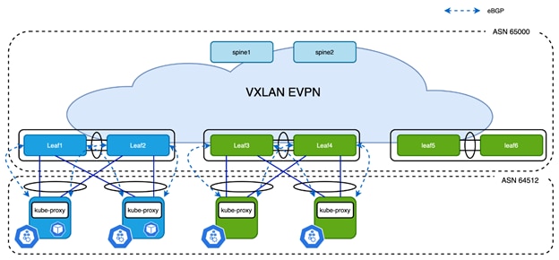
Figure 8
Calico Network AS-per-Cluster Design
Zooming out to whole fabric, as shown in Figure 8, all the Kubernetes nodes peer with local switches to achieve the best scale. Unlike the AS-per-Rack design, a single AS number can be used for the entire cluster which can be easily configured using asNumber of the Calico bgpConfiguration resource. The configuration of leaf switches and Calico nodes is simplified as the node subnet and AS number are identical. The bgpPeer configuration in Calico is still localized to each rack as loopback address on each leaf switches are different.
Note: as a loopback address is used for local BGP control plane in each rack, the address does not have to be unique on leaf switches of each rack as long as the loopback addresses are not advertised to EVPN address family.
One variation of this design is still using the AS-per-Rack model, the modification on default BGP behavior discussed above still applies to it.
Centralized Routing Peering
As discussed above, use of the AS-per-Cluster design simplifies the configuration of physical switches and Calico nodes. If users want to simplify the configuration of Calico even further, instead of peering with local leaf switches, all the Kubernetes nodes peer with one or a pair of switches (called anchor leaf switches). This simplifies the configuration of the physical network and Calico CNI:
● BGP peering configuration is only needed on anchor nodes
● The bgpPeer configuration on Calico nodes is identical as they all peer with same remote addresses
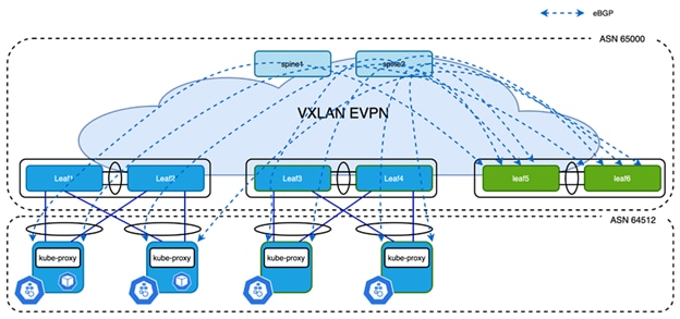
Figure 9
Centralized Routing Peering
In the above example, Leaf5 and Leaf6 are the anchor nodes, all control plane connections are established between these two leaf switches and Kubernetes nodes. It is much easier to maintain this configuration, however it does come with two challenges:
● Number of BGP neighbors supported by a single switch is limited
● North-South (N-S) traffic is not optimized
At the time of writing, most Cisco Nexus fixed switches support 1024 BGP neighbors and modular switches support up to 2000 BGP neighbors. The number of nodes in most Kubernetes clusters is in this range, so in most cases, this first challenge is not really a problem. Also, distributing BGP peering between different anchor nodes is also an option to ease the situation.
Coming to the second challenge, since eBGP is used to form neighbors between Calico and anchor nodes, the next hop address of routes learned on Kubernetes node is always the anycast gateway. The anycast gateway exists on all leaf switches that have Kubernetes node connected to them. So the N-S traffic from Kubernetes is always routed by local switches. However, the traffic coming in from external sources is potentially tromboning via the anchor nodes.
In the following section we discuss the challenges and how Cisco VXLAN EVPN overcomes these challenges and optimizes traffic forwarding without tromboning, keeping the centralized BGP peering approach with the anchor leaf switches.
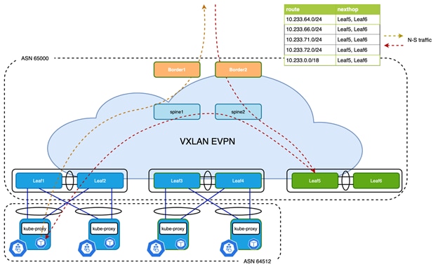
Figure 10
Problem with Centralized Routing Peering
As shown in Figure 10, the /24 Pod subnets allocated to the Kubernetes nodes that are connected to Leaf1 and Leaf3 are learned on anchor nodes leaf5 and Leaf6 and eventually imported into the EVPN address family:
Leaf5# show bgp l2vpn evpn 10.233.64.0
BGP routing table information for VRF default, address family L2VPN EVPN
Route Distinguisher: 10.2.0.5:14 (L3VNI 50008)
BGP routing table entry for [5]:[0]:[0]:[24]:[10.233.64.0]/224, version 2272
Paths: (1 available, best #1)
Flags: (0x000002) (high32 00000000) on xmit-list, is not in l2rib/evpn
Multipath: Mixed
Advertised path-id 1
Path type: local, path is valid, is best path, no labeled nexthop
Gateway IP: 0.0.0.0
AS-Path: 64512 , path sourced external to AS
10.3.0.5 (metric 0) from 0.0.0.0 (10.2.0.5)
Origin IGP, MED not set, localpref 100, weight 0
Received label 50008
Extcommunity: RT:65000:50008 ENCAP:8 Router MAC:700f.6a95.8f25
Path-id 1 advertised to peers:
10.2.0.1 10.2.0.2
Example 13 Example of Pod Subnet in BGP Database
However, when advertising the prefix to spines, the ORIGIN attribute of NLRI will be set to local VTEP address. In this case, it will be the virtual IP address of VPC peer Leaf5 and Leaf6. Border routers receive the path as shown below:
Border1# show bgp l2vpn evpn 10.233.64.0
BGP routing table information for VRF default, address family L2VPN EVPN
Route Distinguisher: 10.2.0.5:14
BGP routing table entry for [5]:[0]:[0]:[24]:[10.233.64.0]/224, version 517
Paths: (2 available, best #1)
Flags: (0x000002) (high32 00000000) on xmit-list, is not in l2rib/evpn, is not in HW
Advertised path-id 1
Path type: internal, path is valid, is best path, no labeled nexthop
Imported to 2 destination(s)
Imported paths list: k8s_cluster default
Gateway IP: 0.0.0.0
AS-Path: 64512 , path sourced external to AS
10.3.0.5 (metric 3) from 10.2.0.1 (10.2.0.1)
Origin IGP, MED not set, localpref 100, weight 0
Received label 50008
Extcommunity: RT:65000:50008 ENCAP:8 Router MAC:700f.6a95.8f25
Originator: 10.2.0.5 Cluster list: 10.2.0.1
Path type: internal, path is valid, not best reason: Neighbor Address, no labeled nexthop
Imported to 2 destination(s)
Imported paths list: k8s_cluster default
Gateway IP: 0.0.0.0
AS-Path: 64512 , path sourced external to AS
10.3.0.5 (metric 3) from 10.2.0.2 (10.2.0.2)
Origin IGP, MED not set, localpref 100, weight 0
Received label 50008
Extcommunity: RT:65000:50008 ENCAP:8 Router MAC:700f.6a95.8f25
Originator: 10.2.0.5 Cluster list: 10.2.0.2
Path-id 1 not advertised to any peer
Example 14 bgp Output on Border
As a result, route 10.233.64.0/24 is pointing to VTEP Leaf5 and Leaf6 on border switches, also the same applies to service IP 10.233.0.0/18 which causes all traffic from external sources to the Kubernetes cluster to always get routed to the anchor nodes first leading to suboptimal forwarding.
Solution for Centralized Routing Peering
Cisco NX-OS provides several tuning operations on the anchor leaf switches, spine switches, and the border switches in order to overcome the deficient routing tromboning while also achieving finer grained load-balancing. The export-gateway-ip option was introduced into Cisco NX-OS on version 9.3(5) and adds an additional attribute called gateway address into EVPN Type-5 advertisements. The gateway IP address is the origin of the prefix, this behavior is documented in secion 9.2.1 of RFC draft [11]. In Calico’s scenario, the gateway address will be filled in with the node IP of the Kubernetes node. This command adds the gateway address for all prefixes imported into EVPN address family, which is not suggested in most cases. A better way to achieve the desired outcome is to use a route-map to filter only the necessary prefixes that are learned from Kubernetes nodes:
ip prefix-list k8s-subnet seq 10 permit 10.233.0.0/18 le 32
ip prefix-list k8s-subnet seq 20 permit 10.233.64.0/20 le 24
!
route-map export-gateway-ip permit 10
match ip address prefix-list k8s-subnet
set evpn gateway-ip use-nexthop
!
vrf context k8s_cluster
vni 50008
rd auto
address-family ipv4 unicast
route-target both auto
route-target both auto evpn
export map export-gateway-ip
Example 15 Selectively Export Gateway IP Address
Commands in the above example must be configured on all anchor nodes. Once a border receives the EVPN Type-5 advertisement with the gateway address set, it picks up the gateway address as next-hop instead of origin to update the RIB, and the switch performs a recursive looking up to find the node’s correct VTEP to forward the packet.
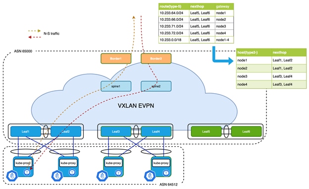
Figure 11 Optimized Forwarding with Recursive Routing
The Pod subnet is unique on each Kubernetes node, meaning each subnet is only advertised from one source. However, the service subnet or IP is advertised from multiple nodes at the same time. As these advertisements look identical from an anchor leaf switches’ perspective when advertising to the EVPN address family, only one of the paths is selected by default. BGP does not evaluate the gateway IP address for multipath decision. With Proportional Multipath, which was introduced in NX-OS 9.3(5), this problem is solved. Detailed information can be found in [12]. The Proportional Multipath feature enables advertising of all the available next hop of service network, this feature enables the switches to consider the gateway address of EVPN Type-5 routes for ECMP and allows the traffic to be forwarded using all the available links stretched across multiple ToR switches:
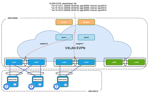
Figure 12 Proportional Multipath of N-S Traffic
In Figure 12, North-South traffic that enters the VXLAN EVPN fabric at border leaf is forwarded across all available Kubernetes nodes proportionately based on the number of Kubernetes nodes connected to each of the leaf switches. This provides the most optimal load distribution by the VXLAN EVPN fabric extended with the proportional load balancing and export-gateway-ip functionality.
Here is an example of the configuration that must be applied to selected switches:
| Spine switches |
Anchor nodes and border |
| route-map add-path permit 10 set path-selection all advertise route-map extcon-rmap-filter deny 10 ! router bgp 65000 address-family l2vpn evpn maximum-paths ibgp 16 additional-paths send additional-paths receive additional-paths selection route-map add-path |
route-map add-path permit 10 set path-selection all advertise route-map extcon-rmap-filter deny 10 ! router bgp 65000 address-family l2vpn evpn maximum-paths ibgp 16 additional-paths send additional-paths receive additional-paths selection route-map add-path vrf k8s_cluster address-family ipv4 unicast advertise l2vpn evpn maximum-paths 16 maximum-paths ibgp 16 additional-paths send additional-paths receive additional-paths selection route-map add-path |
Example 17 Proportional Multipath Configuration
Cisco NX-OS and Calico Configuration
The following configuration is based on what is discussed in the section “Local Routing Peering”, with a single AS used for the entire Kubernetes cluster.
Example of Cisco NX-OS Configuration
Below is an example of the configuration on Leaf switch:
interface loopback2
description k8s_bgp_source
vrf member k8s_cluster
ip address 10.254.254.1/32 tag 12345
!
router bgp 65000
vrf k8s_cluster
address-family ipv4 unicast
advertise l2vpn evpn
maximum-paths 16
maximum-paths ibgp 16
neighbor 10.13.0.0/24
remote-as 64512
update-source loopback2
ebgp-multihop 16
address-family ipv4 unicast
as-override
disable-peer-as-check
Example 18 Example of Leaf Switch for Peering with Local Kubernetes Nodes
As shown in Example 18, the Leaf switch uses a loopback address to establish eBGP neighborship with Kubernetes nodes in the same rack. Peering with the entire node subnet can simplify the BGP neighbor configuration, and as-override and disable-peer-as-check must be configured under unicast address family. The number of eBGP multipath needs to be adjusted to accommodate the number of Kubernetes nodes in the same rack.
Example of Calico Configuration
# calicoctl get bgpConfig -o yaml
apiVersion: projectcalico.org/v3
items:
- apiVersion: projectcalico.org/v3
kind: BGPConfiguration
metadata:
creationTimestamp: "2021-07-02T21:46:14Z"
name: default
resourceVersion: "2901"
uid: ed97898c-2161-4eab-87aa-9c6b3d95c7d4
spec:
asNumber: 64512
listenPort: 179
logSeverityScreen: Info
nodeToNodeMeshEnabled: false
serviceClusterIPs:
- cidr: 10.233.0.0/18
kind: BGPConfigurationList
metadata:
resourceVersion: "2185548"
Example 19 Calico Global BGP Configuration
In the output below is an example of a route learned from Calico on a leaf switch:
Leaf1# show ip route bgp vrf k8s_cluster
IP Route Table for VRF "k8s_cluster"
'*' denotes best ucast next-hop
'**' denotes best mcast next-hop
'[x/y]' denotes [preference/metric]
'%<string>' in via output denotes VRF <string>
<omitted>
10.233.0.0/18, ubest/mbest: 2/0 <<< service subnet
*via 10.13.0.1, [20/0], 21:23:07, bgp-65000, external, tag 64512
*via 10.13.0.2, [20/0], 21:23:07, bgp-65000, external, tag 64512
10.233.50.74/32, ubest/mbest: 1/0 <<< service ip
*via 10.13.0.1, [20/0], 10:15:46, bgp-65000, external, tag 64512
10.233.64.0/24, ubest/mbest: 1/0
*via 10.3.0.7%default, [200/0], 02:56:26, bgp-65000, internal, tag 64512, segid: 50008 tunnelid: 0xa030007 encap: VXLAN
10.233.66.0/24, ubest/mbest: 1/0 <<< pod subnet learned from remote node
*via 10.3.0.7%default, [200/0], 02:59:50, bgp-65000, internal, tag 64512, segid: 50008 tunnelid: 0xa030007 encap: VXLAN
10.233.71.0/24, ubest/mbest: 1/0 <<< pod subnet learned from local node
*via 10.13.0.1, [20/0], 21:23:07, bgp-65000, external, tag 64512
10.233.72.0/24, ubest/mbest: 1/0
*via 10.13.0.2, [20/0], 21:23:07, bgp-65000, external, tag 64512
encap: VXLAN
Example 20 Routing Table of Leaf Switch
As shown in Example 20, the service subnet is load balanced between local nodes. The next-hop of pod subnet that is learned from a remote node is pointing to the remote VTEP address, In this case, it is the VIP of the remote VPC peer. While on the border, ECMP is available by pointing to VTEPs that have the Kubernetes node connected:
Border1# show ip route 10.233.0.0/18 vrf k8s_cluster
IP Route Table for VRF "k8s_cluster"
'*' denotes best ucast next-hop
'**' denotes best mcast next-hop
'[x/y]' denotes [preference/metric]
'%<string>' in via output denotes VRF <string>
10.233.0.0/18, ubest/mbest: 2/0
*via 10.3.0.5%default, [200/0], 03:11:47, bgp-65000, internal, tag 64512, segid: 50008 tunnelid: 0xa030005 encap: VXLAN
*via 10.3.0.7%default, [200/0], 03:11:47, bgp-65000, internal, tag 64512, segid: 50008 tunnelid: 0xa030007 encap: VXLAN
Example 21 ECMP Route of Service Subnet on Border
In the output above, the two available paths for the service subnet point to the VIP of remote vPC peers.
Designing a Calico network using non-overlay mode is mainly a concern of leveraging BGP configuration options and best practices. Cisco NX-OS’s capabilities for BGP-based IP fabrics supports the attachment and transport of Kubernetes workload and optimizes the configuration. Further optimizations are available with VXLAN EVPN, the removal of traffic tromboning and the proportional multi-path functionality. Most of the design considerations made are similar to attaching Virtual Network Functions (VNF) to a Data Center fabric. Cisco Nexus platforms offer users a simple and resilient fabric that can carry highly available and large-scale Kubernetes clusters.
[1]. https://www.projectcalico.org/
[3]. https://docs.projectcalico.org/networking/determine-best-networking#networking-options
[4]. https://docs.projectcalico.org/reference/architecture/overview
[6]. https://docs.projectcalico.org/reference/architecture/design/l3-interconnect-fabric#recommendation
[7]. https://datatracker.ietf.org/doc/html/rfc7938
[8]. https://wiki.linuxfoundation.org/networking/bonding
[9]. https://kubernetes.io/docs/concepts/services-networking/service/
[11]. https://datatracker.ietf.org/doc/html/draft-ietf-bess-evpn-inter-subnet-forwarding-13