Cisco Validated Design with Panasonic - A blueprint for IP Media Success
Available Languages
Bias-Free Language
The documentation set for this product strives to use bias-free language. For the purposes of this documentation set, bias-free is defined as language that does not imply discrimination based on age, disability, gender, racial identity, ethnic identity, sexual orientation, socioeconomic status, and intersectionality. Exceptions may be present in the documentation due to language that is hardcoded in the user interfaces of the product software, language used based on RFP documentation, or language that is used by a referenced third-party product. Learn more about how Cisco is using Inclusive Language.
- US/Canada 800-553-2447
- Worldwide Support Phone Numbers
- All Tools
 Feedback
 Feedback
Cisco Nexus 9000 Series Switches
Panasonic IP Production Products
Studio Camera System, PTZ Camera, and IP/SDI Gateway
Considerations within a Spine-Leaf Topology
Uplink Bandwidth from Leaf Switches
Resilient Network with ST 2022-7 Redundancy
Media Flow and Device Management by Broadcast Controller
Cisco Validated Design Topology and Switch Configuration
Cisco Validated Design Topology
Baseline Switch Configuration for ST 2110 Network
Configuration for ASM with Single Spine
Configuration for ASM with Two Spines
1. Connectivity check of the devices
2. Verification of Control Operation
3. Verification of System Performance
4. Verification of PTP synchronization
5.1 Verification of system behavior in the event of a network switch or link failure
5.2 Verification of system behavior in the event of a PTP device or cable failure
5.3 Verification of backup operation for KAIROS
The media industry is undergoing a significant transformation as it shifts from traditional broadcast infrastructures to modern IP-based workflows. This evolution is driven by the need for greater flexibility, scalability, and efficiency in content production and distribution. Central to this shift are two key technologies: Serial Digital Interface (SDI) and SMPTE ST 2110.
SDI has long been the standard for transporting uncompressed video and audio signals in broadcast environments. However, as media production demands growth, SDI’s limitations in scalability and flexibility have become apparent. SMPTE ST 2110 addresses these challenges by defining a suite of standards for professional media over IP networks, enabling the transport of separate video, audio, and ancillary data streams in real time with precise synchronization.
This transition to SMPTE ST 2110 allows broadcasters to leverage IP networks for uncompressed media transport, supporting higher resolutions and more complex workflows. It also facilitates interoperability and integration with IT infrastructure, paving the way for innovations such as remote production and cloud-based workflows.
However, the transition to ST 2110 is not merely a change in transport protocol, it marks a shift in system architecture and operational workflows. Unlike SDI’s dedicated point-to-point setup, ST 2110 runs over shared IP networks, using multicast for media distribution and PTP for synchronization. These elements require careful network design and a solid understanding of IP principles to ensure reliable and synchronized media transport.
Over the past several years, Panasonic and Cisco have deployed ST 2110 infrastructure across a wide range of industries, including broadcast, live production, and corporate media environments. These deployments have provided valuable insights into the practical challenges and requirements of ST 2110 network design.
This document presents a Cisco Validated Design with Panasonic for ST 2110 network based on those real-world experiences and established best practices.
This document targets individuals and teams such as broadcasters, system integrators, network engineers, sales engineers, and field consultants involved in designing IP-based production infrastructure.
The purpose of this document is to provide guidance for building and deploying an ST 2110 network infrastructure for media production environments. It outlines best practices, design considerations, and practical insights that support successful implementation.
The following components are required to deploy this solution:
● Cisco IP Fabric for Media
● Cisco Nexus 9000 Series Switches
● Panasonic IP Production products
Cisco IP Fabric for Media (IPFM) is an IP‑based network infrastructure solution built for live production and broadcast workflows. Built on Cisco Nexus 9000 Series switches, it delivers predictable multicast performance and operational visibility across flexible spine‑and‑leaf or modular switch topologies. Using Cisco Non‑blocking Multicast (NBM), an intelligent bandwidth management algorithm, IPFM enables transport of high‑bandwidth audio, video, and ancillary data with deterministic behavior, strong security, and high availability.
Cisco Nexus 9000 Series Switches
Cisco Nexus 9000 Series switches deliver high‑performance, data center‑class networking built for scale, low latency, and operational efficiency across a range of form factors. These switches also provide line-rate multicast replication with minimal jitter. Each switch can operate as a Precision Time Protocol (PTP) boundary clock and can support the SMPTE ST 2110 and AES67 profiles.
Panasonic IP Production Products
Panasonic’s products integrate seamlessly with Cisco’s IP-based infrastructure, forming the foundation of a validated design that empowers customers to adapt to evolving requirements, accommodate higher resolutions, and support distributed production teams.
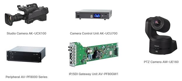
Studio Camera System, PTZ Camera, and IP/SDI Gateway
The 4K studio camera AK-UCX100 and camera control unit AK-UCU700 together form a high-performance 4K studio camera system optimized for IP-based production environments. The AK-UCX100 can operate independently or in conjunction with the AK-UCU700 for enhanced control and signal routing.
The AW-UE160 is Panasonic’s flagship 4K PTZ (Pan-Tilt-Zoom) camera, engineered for high-end broadcast, live event production, and remote shooting applications. It combines studio-grade image quality with advanced IP connectivity and intelligent automation features.
All units support SMPTE ST 2110, enabling seamless integration into IP-based production systems.
The AV-PF80GW1 is an IP/SDI gateway unit compatible with the AV-PF8000 peripheral series. It can convert up to eight HD-SDI signals or up to two 12G-SDI signals into SMPTE ST 2110 streams. Video format (HD or 4K) and the number of input/output channels can be configured via the GUI software.
Note: AV-PF8000 series including AV-PF80GW1 is currently sold only in the Japanese market.
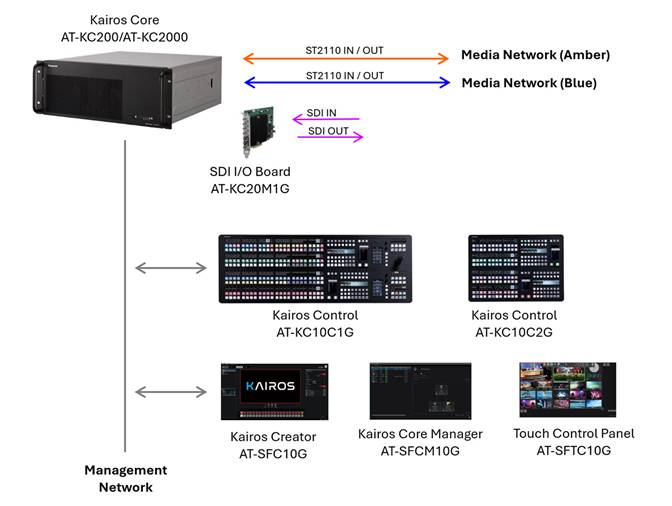
Central to the workflow is the IT/IP platform KAIROS, which introduces an innovative approach to live video production with its advanced architecture for central processing and switching. The KAIROS system, comprising Kairos Core (mainframe), Kairos Control (control panel), and Kairos Creator (GUI software) offers comprehensive multi-format support including ST 2110, NDI, and SRT alongside features such as unlimited scenes and layers, CANVAS functionality, open architecture.
Furthermore, various hardware and software options can be implemented, such as the SDI I/O Board for connecting to legacy devices, the Kairos Core Manager for configuring backup systems for the mainframe, and the Touch Control Panel Software for live operation through intuitive touch-based interaction enabling the construction of a system that meets high demands for connectivity, reliability and operability. By connecting directly to Cisco’s IP Fabric for Media via ST 2110, KAIROS ensures seamless interoperability and robust performance.
Panasonic’s broadcast controller ecosystem, featuring the Panasonic System Manager (PSM) and Panasonic System Surveillance (PSS), provides comprehensive control and monitoring capabilities with straightforward and intuitive GUI, further enhancing the reliability and efficiency of the entire solution.
Note: PSM and PSS are currently sold only in the Japanese market.
This chapter outlines the key considerations and presents a recommended ST 2110 network design for optimal performance, reliability, flexibility, and scalability.
A Layer 3 network is strongly recommended over a Layer 2 network for large-scale deployments, especially when multiple network switches are involved, because Layer 3 networks allow for more precise control of multicast traffic and more efficient bandwidth utilization.
By enabling Non-Blocking Multicast (NBM) on Cisco Nexus 9000 series switches in conjunction with PIM, multicast traffic can be distributed efficiently across multiple network paths, improving bandwidth utilization and providing resiliency for existing multicast flows.
Without NBM, in environments with multiple links between two switches, only a subset of those links may be utilized for multicast traffic, potentially leading to packet loss due to congestion on a single link. NBM prevents uneven utilization of multiple links and enables balanced multicast traffic distribution across them.
In the event of a link failure, blocked traffic is redistributed across the remaining active links. With NBM enabled, existing multicast flows on those active links remain unaffected.
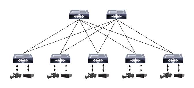
When designing a network that involves multiple switches, the Spine-Leaf topology is the starting point for ST 2110 architectures due to its high flexibility and scalability. In this topology, endpoints that send or receive media streams are preferred to be connected to the Leaf switches. This design simplifies traffic management, ensures predictable latency, and enables efficient multicast handling. The Spine layer is dedicated to high-speed inter-switch forwarding, while the Leaf layer manages stream distribution and IGMP-based multicast control.
In larger ST 2110 deployments, a single Spine switch may not be sufficient to ensure stable operation. Adding a second Spine switch improves bandwidth distribution and supports scalability as more Leaf switches are introduced. It also provides an alternate path if one Spine switch becomes unavailable due to unexpected issues, helping minimize service interruptions.
Although a three-tier architecture incorporating a Super Spine layer can be considered for very large-scale ST 2110 deployments, a two-tier Spine-Leaf topology is recommended. Its simplicity and ability to minimize latency and jitter make it better suited for real-time media transport.
Considerations within a Spine-Leaf Topology
In a spine-and-leaf topology, the network design can be further refined based on the facility’s operational structure and the network’s scale.
For example, in broadcast environments with multiple control rooms, one or more Leaf switches can be assigned to each room according to its operational role. This approach aligns the network topology with the functional layout of the facility, simplifying configuration and maintenance within each room.
Additional factors such as the physical location of endpoints, the role of each endpoint, and expected traffic patterns between endpoints should also be considered. Grouping endpoints based on these criteria and assigning dedicated Leaf switches to each group can lead to more efficient resource utilization. This also helps with streamline configuration and maintenance.
Uplink Bandwidth from Leaf Switches
In a Spine-Leaf network, it is recommended that the uplink bandwidth from each Leaf to the Spine be sufficient to cover the total bandwidth of all endpoints connected to that Leaf switch. This ensures non-blocking architecture and prevents link overflows during peak media traffic.
The number of endpoints and the bandwidth requirements of each endpoint are key factors in selecting appropriate switch models.
The total number of devices connected to the network directly affects the required port density of each switch. Leaf switches must provide enough ports to accommodate all endpoints within their assigned group. It is also recommended to reserve additional ports on each switch to allow for future expansion of capacity and operational flexibility.
In addition, Leaf switches must be selected based on the bandwidth demands of each connected endpoint, as well as the aggregate bandwidth required for uplink connections to the Spine switches. To ensure a non-blocking architecture, the uplink bandwidth of a Leaf switch must be sufficient to manage the combined bandwidth of all its connected endpoints.
Spine switches must offer sufficient port density and bandwidth to accommodate uplink connections from all Leaf switches. High-bandwidth switches supporting 400G or 800G link speeds can be an optimal choice for this purpose. As with Leaf switches, it is advisable to reserve additional ports on Spine switches to allow for future scalability.
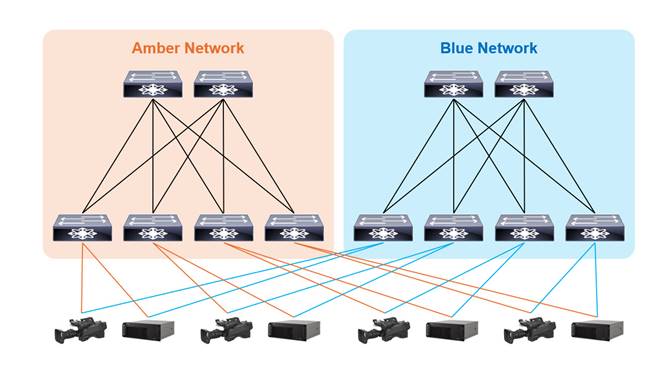
Resilient Network with ST 2022-7 Redundancy
To achieve a highly reliable ST 2110 infrastructure, a fully redundant network can be implemented in conjunction with the hitless protection switching mechanism defined in ST 2022-7. This standard enables endpoints to receive identical media streams over two separate network paths and seamlessly switch between them without packet loss or disruption, even in the event of a failure on one path.
Incorporating ST 2022-7 into the network design not only improves resilience but also aligns with industry best practices for broadcast-grade reliability.
Accurate clock synchronization is essential in ST 2110 environments. Precision Time Protocol (PTP), as defined by IEEE 1588, is used to synchronize devices with sub-microsecond accuracy, enabling precise alignment across distributed endpoints.
When designing an ST 2110 network with PTP, it is considered best practice to configure network switches as Boundary Clocks. This helps distribute the PTP load across the network, rather than placing it solely on the PTP Grandmaster, resulting in a more scalable and efficient system.
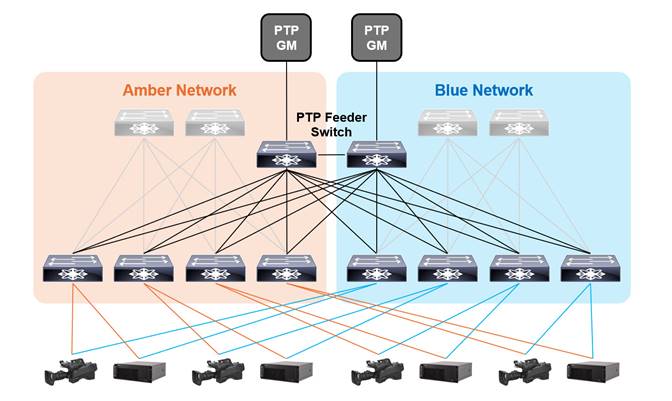
A redundant PTP infrastructure is essential for maintaining reliable time synchronization in ST 2110 environments. By deploying multiple PTP Grandmasters and designing the network with redundant paths, the system can continue to deliver accurate timing even in the event of a failure.
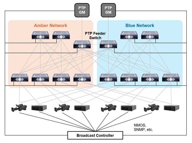
In environments with multiple Leaf switches, it is advisable to install dedicated PTP feeder switches. This allows Spine switches to focus on forwarding media traffic, simplifies maintenance, and supports scalable PTP distribution. PTP feeder switches are dedicated to PTP communication and do not participate in forwarding media traffic.
To maintain high timing accuracy in PTP distribution, it is important to minimize the number of intermediary switches between the PTP Grandmaster and the endpoints. As the number of switch hops increases, timing degradation, such as increased jitter and latency, can accumulate and negatively impact synchronization precision. It is recommended to limit the number of switches in the PTP path to two, and at most three, to ensure reliable and accurate delivery time across the network.
To ensure consistent and reliable PTP distribution across the network, it is important to establish direct connections between first-tier PTP switches, such as dedicated PTP feeder switches, exclusively for PTP communication. This design helps maintain timing integrity throughout the whole network and reduces the number of intermediary switches between the PTP Grandmaster and the endpoints.
The SMPTE ST 2059-2:2021 profile defines the default values of the following PTP parameters.
| Parameters |
Default |
Recommended Value |
Configuration Scope |
| PTP Domain |
127 |
Avoid using 127 |
System-wide |
| Announce Interval |
0 (1 Hz) |
0 (or -2) |
|
| Announce Timeout |
3 |
3 |
|
| Sync Interval |
-3 (8 Hz) |
-3 |
|
| Delay Request Minimum Interval |
-3 (8 Hz) |
-3 |
|
| Priority 1 |
128 |
Role-based |
Each Switch |
| Priority 2 |
128 |
Role-based |
Note: ST 2059-2:2015 defines the default value of Announce Interval as -2 (4 Hz).
Priority 1 and Priority 2 must be configured individually for each switch to ensure deterministic PTP roles and system behavior, including in the event of network failures.
Using PTP Domain 127 is discouraged, as many devices default to this value. If such devices are connected to the network before being properly configured or if they are misconfigured, then they may cause unexpected behavior, including synchronization issues and instability in the entire system.
It is essential to ensure that the system-wide parameters listed above are consistently applied to all PTP-aware devices, including PTP Grandmasters, Boundary Clocks (such as switches), and Endpoints across the entire network. Uniform configuration throughout the network is critical for reliable time synchronization and ensuring interoperability.
The following example shows how network switches are determined. The example network is designed for a broadcaster with the following conditions:
● There are 10 control rooms.
● Each control room is assigned dedicated leaf switches to ensure efficient operation and maintenance.
● Some equipment is shared among control rooms to optimize resource utilization, and these devices are connected to different leaf switches than those assigned to the control rooms.
● Interface speed of each device and device counts for each control room and shared equipment are as follows:
Control Room ( x 10)
| Device Type |
Interface Speed |
Count |
| Camera, IP Gateway, Waveform Monitor, etc. |
25 Gbps |
57 |
| Audio Device, etc. |
10 Gbps |
2 |
Shared Equipment
| Device Type |
Interface Speed |
Count |
| Video Switcher, Multi Viewer, etc. |
100 Gbps |
56 |
● Each Leaf switch connects to two PTP feeder switches.
Each Leaf Switch
| Connection |
Interface Speed |
Count |
| PTP Feeder |
10 Gbps |
2 |
For each control room, considering the number of 10-Gbps and 25-Gbps endpoints and the required uplink bandwidth which must accommodate the total bandwidth of all devices connected to the switch, two Nexus 93400LD-H1 switches can be deployed as shown below.
Leaf - Control Room ( x 10)
| Switch Model |
Connection |
Port Speed |
Count |
| 93400LD-H1 (1) |
Uplink |
400 Gbps |
2 |
| Device |
25 Gbps |
30 |
|
| PTP Feeder |
10 Gbps |
2 |
|
| 93400LD-H1 (2) |
Uplink |
400 Gbps |
2 |
| Device |
25 Gbps |
27 |
|
| 10 Gbps |
2 |
||
| PTP Feeder |
10 Gbps |
2 |
Note: The above table shows the switches required for each of the Amber and Blue networks individually.
For the shared equipment, two Nexus 9364D-GX2A switches can be deployed.
Leaf - Shared Equipment
| Switch Model |
Connection |
Port Speed |
Count |
| 9364D-GX2A (1) |
Spine |
400 Gbps |
8 |
| Device |
100 Gbps |
32 |
|
| PTP Feeder |
10 Gbps |
2 |
|
| 9364D-GX2A (2) |
Spine |
400 Gbps |
6 |
| Device |
25 Gbps |
24 |
|
| PTP Feeder |
10 Gbps |
2 |
Note: The above table shows the switches required for each of the Amber and Blue networks individually.
The total uplink bandwidth is as follows.
● Control rooms : (2 x 400-Gbps + 2 x 400-Gbps) x 10 = 40 x 400-Gbps = 16000 Gbps
● Shared Equipment : 8 x 400-Gbps + 6 x 400-Gbps = 14 x 400-Gbps = 5600 Gbps
● Total : 40 x 400-Gbps + 14 x 400-Gbps = 54 x 400-Gbps = 21600 Gbps
To support all uplink connections and ensure a robust Spine layer, two Nexus 9364D-GX2A switches can be deployed as Spine switches.
Spine
| Switch Model |
Connection |
Port Speed |
Count |
| 9364D-GX2A (1) |
Leaf |
400 Gbps |
27 |
| 9364D-GX2A (2) |
Leaf |
400 Gbps |
27 |
Note: The above table shows the switches required for each of the Amber and Blue networks individually.
The total number of Leaf switches is 22 for each of the Amber and Blue networks, and the Nexus 93180YC-FX3 meets the necessary port count.
PTP Feeder
| Switch Model |
Connection |
Port Speed |
Count |
| 93180YC-FX3 |
Leaf (Amber) |
10 Gbps |
22 |
| Leaf (Blue) |
10 Gbps |
22 |
|
| PTP Feeder |
10 Gbps |
1 |
|
| PTP Grandmaster |
10 Gbps |
1 |
Note: The above table shows the switches required for each of the Amber and Blue networks individually.
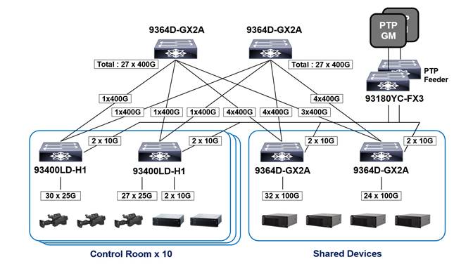
This diagram illustrates the Spine and Leaf switches deployed in the Amber network. An identical set of switches is required for the Blue network. The PTP Feeder switches shown represent both units in the redundant configuration.
Media Flow and Device Management by Broadcast Controller
In ST 2110 networks, dynamic and efficient management of devices and media flows is essential to ensure operational efficiency and scalability.
Serving as the central orchestration point, the Broadcast Controller enables media flow routing between senders and receivers through the NMOS (Networked Media Open Specifications) framework, facilitating seamless coordination across the network.
Broadcast Controllers with device monitoring capabilities track the status of connected devices via SNMP or other monitoring protocols and trigger alarms when issues are detected, enhancing reliability and operational awareness.
Cisco Validated Design Topology and Switch Configuration
This chapter presents the topology design and a recommended switch configuration for ST 2110 networks, covering key protocols and features such as OSPF, PIM, NBM, and PTP.
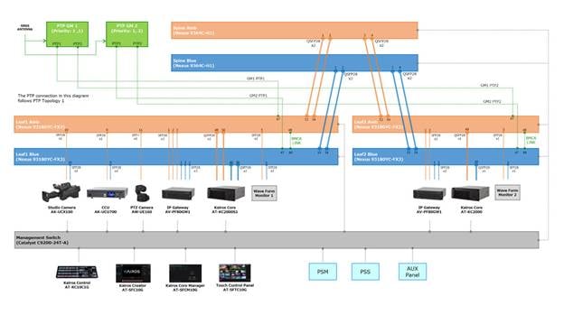
Cisco Validated Design Topology
This section provides a detailed overview of the network and PTP topology, including all components tested as part of the Cisco Validated Design, seamlessly integrated with Panasonic products.
Baseline Switch Configuration for ST 2110 Network
The following is the baseline configuration for Spine, Leaf, and PTP feeder switches in an ST 2110 network, where all endpoints support IGMP version 3 and SSM (Source-Specific Multicast),so SM (Any-Source Multicast) support is not required.
| Command |
Spine |
Leaf |
PTP Feeder |
Note |
| OSPF |
||||
| feature ospf |
|
|
|
|
| router ospf 1 router-id X.X.X.X |
|
|
|
*[1] |
| PIM |
||||
| feature pim |
|
|
|
|
| ip pim prune-on-expiry |
|
|
|
|
| ip pim ssm range none |
|
|
|
|
| NBM |
||||
| feature nbm |
|
|
|
|
| nbm mode pim-active |
|
|
|
|
| hardware access-list tcam region ing-racl 256 hardware access-list tcam region ing-l3-vlan-qos 256 hardware access-list tcam region ing-nbm 1536 |
|
|
|
|
| ip multicast multipath nbm |
|
|
|
|
| nbm host-policy sender default permit receiver default permit pim default permit |
|
|
|
|
| nbm flow-policy policy <NAME> bandwidth <bandwidth reservation> ip group-range <first multicast address> to <last multicast address> |
|
|
|
*[2] |
| PTP |
||||
| feature ptp |
|
|
|
|
| policy-map type control-plane pmn-copp-policy-strict class pmn-copp-class-redirect set cos 1 police cir 1500 kbps bc 128000 bytes conform transmit violate drop |
|
|
|
*[3] |
| ptp domain <PTP Domain> |
|
|
|
|
| ptp priority1 <Priority1> |
|
|
|
|
| ptp priority2 <Priority2> |
|
|
|
|
| ptp source X.X.X.X |
|
|
|
*[1] |
| Interface : Spine, Leaf (Spine-Leaf) |
||||
| interface Ethernet1/a |
|
|
|
*[4] |
| ip address A.A.A.A/30 |
|
|
|
*[4] |
| ip ospf network point-to-point |
|
|
|
|
| ip router ospf 1 area 0.0.0.0 |
|
|
|
|
| ip pim sparse-mode |
|
|
|
|
| no shutdown |
|
|
|
|
| Interface : Leaf (Leaf-Endpoint) |
||||
| interface Ethernet1/b |
|
|
|
*[4] |
| ptp |
|
|
|
|
| ptp delay-request minimum interval smpte-2059-2 -3 |
|
|
|
|
| ptp announce interval smpte-2059-2 -2 |
|
|
|
|
| ptp sync interval smpte-2059-2 -3 |
|
|
|
|
| ptp announce timeout smpte-2059-2 3 |
|
|
|
|
| ip address B.B.B.B/30 |
|
|
|
*[4] |
| ip ospf passive-interface |
|
|
|
|
| ip router ospf 1 area 0.0.0.0 |
|
|
|
|
| ip pim sparse-mode |
|
|
|
|
| ip igmp version 3 |
|
|
|
|
| ip igmp immediate-leave |
|
|
|
|
| ip igmp suppress v3-gsq |
|
|
|
|
| no shutdown |
|
|
|
|
| Interface : Leaf (Leaf-PTP Feeder) |
||||
| interface Ethernet1/c |
|
|
|
*[4] |
| ptp |
|
|
|
|
| ptp delay-request minimum interval smpte-2059-2 -3 |
|
|
|
|
| ptp announce interval smpte-2059-2 -2 |
|
|
|
|
| ptp sync interval smpte-2059-2 -3 |
|
|
|
|
| ptp announce timeout smpte-2059-2 3 |
|
|
|
|
| ip address C.C.C.C/30 |
|
|
|
*[4] |
| no shutdown |
|
|
|
|
| Interface : PTP Feeder (Leaf-PTP Feeder) |
||||
| interface Ethernet1/d |
|
|
|
*[4] |
| ptp |
|
|
|
|
| ptp role master |
|
|
|
|
| ptp delay-request minimum interval smpte-2059-2 -3 |
|
|
|
|
| ptp announce interval smpte-2059-2 -2 |
|
|
|
|
| ptp sync interval smpte-2059-2 -3 |
|
|
|
|
| ptp announce timeout smpte-2059-2 3 |
|
|
|
|
| ip address D.D.D.D/30 |
|
|
|
*[4] |
| no shutdown |
|
|
|
|
| Interface : PTP Feeder (PTP Feeder-PTP Feeder) |
||||
| interface Ethernet1/e |
|
|
|
*[4] |
| ptp |
|
|
|
|
| ptp delay-request minimum interval smpte-2059-2 -3 |
|
|
|
|
| ptp announce interval smpte-2059-2 -2 |
|
|
|
|
| ptp sync interval smpte-2059-2 -3 |
|
|
|
|
| ptp announce timeout smpte-2059-2 3 |
|
|
|
|
| ip address E.E.E.E/30 |
|
|
|
*[4] |
| no shutdown |
|
|
|
|
| Loopback Interface |
||||
| interface loopback0 |
|
|
|
|
| ip address X.X.X.X/32 |
|
|
|
*[4] |
| ip router ospf 1 area 0.0.0.0 |
|
|
|
|
| ip pim sparse-mode |
|
|
|
|
|
|
|
|
|
|
Configuration for ASM with Single Spine
The following is an additional configuration to supplement the baseline setup for an ST 2110 network with a single Spine, where some endpoints support only ASM and not SSM; therefore, RP (Rendezvous Point) configuration is required.
| Command |
Spine |
Leaf |
PTP Feeder |
Note |
| PIM |
|
|
|
|
| ip pim rp-address S.S.S.S route-map mcast-asm-range |
|
|
|
*[5] |
| route-map mcast-asm-range permit 10 match ip multicast group 239.0.0.0/8 |
|
|
|
*[6] |
| ip pim spt-threshold infinity group-list mcast-spt-infinity |
|
|
|
|
| route-map mcast-spt-infinity permit 10 match ip multicast group 224.0.0.0/4 |
|
|
|
|
Configuration for ASM with Two Spines
The following is an additional configuration to supplement the baseline setup for an ST 2110 network with a two Spines, where some endpoints support only ASM and not SSM.
| Command |
Spine |
Leaf |
PTP Feeder |
Note |
| PIM |
||||
| ip pim rp-address R.R.R.R route-map mcast-asm-range |
|
|
|
*[7] |
| route-map mcast-asm-range permit 10 match ip multicast group 239.0.0.0/8 |
|
|
|
*[6] |
| ip pim spt-threshold infinity group-list mcast-spt-infinity |
|
|
|
|
| route-map mcast-spt-infinity permit 10 match ip multicast group 224.0.0.0/4 |
|
|
|
|
| NBM |
||||
| nbm flow asm range 239.0.0.0/8 |
|
|
|
*[6] |
| MSDP : Spine1 |
||||
| feature msdp |
|
|
|
|
| ip msdp originator-id loopback0 |
|
|
|
|
| ip msdp peer S2.S2.S2.S2 connect-source loopback0 |
|
|
|
*[8] |
| ip msdp sa-policy S2.S2.S2.S2 msdp-mcast-all out |
|
|
|
*[8] |
| ip msdp mesh-group S2.S2.S2.S2 spine-mesh |
|
|
|
*[8] |
| route-map msdp-mcast-all permit 10 match ip multicast group 224.0.0.0/4 |
|
|
|
|
| MSDP : Spine2 |
||||
| feature msdp |
|
|
|
|
| ip msdp originator-id loopback0 |
|
|
|
|
| ip msdp peer S1.S1.S1.S1 connect-source loopback0 |
|
|
|
*[9] |
| ip msdp sa-policy S1.S1.S1.S1 msdp-mcast-all out |
|
|
|
*[9] |
| ip msdp mesh-group S1.S1.S1.S1 spine-mesh |
|
|
|
*[9] |
| route-map msdp-mcast-all permit 10 match ip multicast group 224.0.0.0/4 |
|
|
|
|
| loopback Interface : Spine1, Spine2 (RP) |
|
|
|
|
| interface loopback100 |
|
|
|
|
| ip address R.R.R.R/32 |
|
|
|
*[7] |
| ip router ospf 1 area 0.0.0.0 |
|
|
|
|
| ip pim sparse-mode |
|
|
|
|
| no shutdown |
|
|
|
|
The following configurations are recommended for easy maintenance and troubleshooting.
| Command |
Spine |
Leaf |
PTP Feeder |
Note |
| LLDP |
||||
| feature lldp |
|
|
|
|
| clock Protocol |
|
|
|
|
| clock protocol ptp vdc 1 |
|
|
|
|
This section provides a high-level summary of the validation that is done for this CVD.
| Test Items |
Network Topology |
Usage |
Switch model |
OS Version |
| 1. Connectivity check of the devices 2. Verification of Control Operation 3. Verification of System Performance 4. Verification of PTP synchronization 5. Failure Scenario Test |
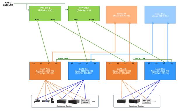
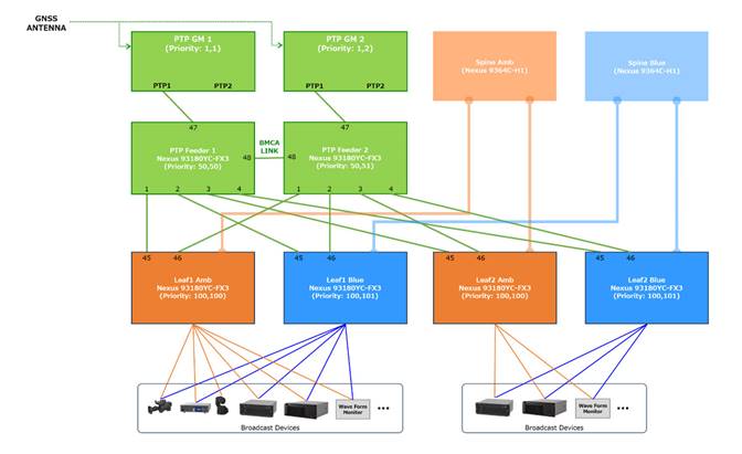
Figure 10. Network Topology for CVD Figure 11. PTP Topology 1 – Leaf switches are directly connected to GM Figure 12. PTP Topology 2 – Leaf switches are connected to GM via feeder switches |
Spine (Amber, Blue) |
Nexus 9364C-H1 |
10.5(3) |
| Leaf1(Amber, Blue), Leaf2(Amber, Blue) |
Nexus 93180YC-FX3 |
10.5(3) |
||
| PTP Feeder1, |
Nexus 93180YC-FX3 |
10.5(3) |
||
| 6. PTP Stress Test |
Figure 13. Network Topology for PTP Stress Test |
Leaf |
Nexus C9332D-GX2B |
10.5(3) |
| PTP Feeder |
Nexus 93180YC-FX3 |
10.5(3) |
1. Connectivity check of the devices
| Test Case |
Result |
| Check the link status via the LED indicators on each port of the leaf switches |
OK |
| Verify connectivity by sending commands to the corresponding ports of each device from the leaf switches |
OK |
2. Verification of Control Operation
| Test Case |
Result |
| Activate NMOS configuration on each device and confirm that the device information is registered in RDS |
OK |
| Confirm that RDS information is registered in the PSM |
OK |
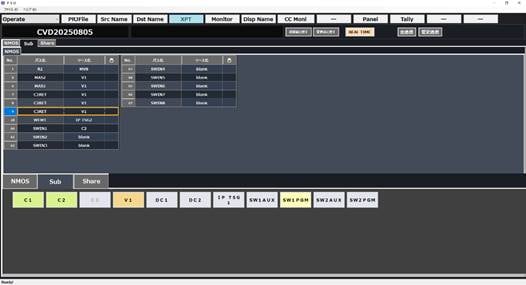
| Confirm that the registered senders and receivers appear correctly on the crosspoint interface in the PSM |
OK |
| Confirm that the registered senders and receivers are properly configured on the AUX panel |
OK |
| Confirm that the registered senders and receivers can be switched on the crosspoint interface in the PSM or AUX panel, and that video, audio, and ANC are switched correctly according to the configured stream. |
OK |
| Test Case |
Result |
| Change the names of destination/source in the PSM GUI menu, and confirm that the updated name is reflected in the crosspoint interface in the menu |
OK |
| Change the names of destination/source in the PSM GUI menu, and confirm that the updated name is reflected on the corresponding buttons of AUX panel |
OK |
| Switch the input sources for KAIROS using the crosspoint interface or AUX panel and confirm that the source names are displayed on the KAIROS MV and Control panel |
OK |
| Change the names of destination/source in the PSM GUI menu, and confirm that the updated name is reflected on the KAIROS MV and Control panel |
OK |
| Test Case |
Result |
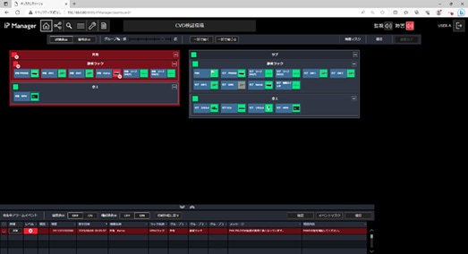
| Using the PSS device registration interface, register the devices and the network switches for monitoring and confirm that they appear on the dashboard and related menu |
OK |
| Confirm that the monitoring process begins for the registered devices and the network switches on the dashboard and other relevant views, and that the status icons reflect changes through color updates |
OK |
| Shut down the monitored device or network switch, and confirm that the alarm appears on the corresponding menu |
OK |
| Restart the monitored device or network switch, and confirm that the alarm indication is cleared from the corresponding menu |
OK |
| Shut down one of the power inputs on the redundant power supply device and confirm that the alarm is displayed on the corresponding menu |
OK |
| Restore the power supply and confirm that the alarm indication is cleared from the corresponding menu |
OK |
| Open the device detail view from the dashboard, and confirm that the lock status and GMID are shown on the PTP monitoring menu |
OK |
| Open the media switch detail view from the dashboard, and confirm that the lock status and GMID are shown on the PTP monitoring menu |
OK |
| Disconnect the connection between the media switch and PTP Grandmaster and confirm that the alarm is displayed on the corresponding menu |
OK |
| Restore the connection between the media switch and PTP Grandmaster and confirm that the alarm indication is cleared from the corresponding menu |
OK |
| Open the media switch detail view from the dashboard, and confirm that the link status and bandwidths are shown on the network monitoring menu |
OK |
| Disconnect the connection to the media switch and confirm that the alarm is displayed on the corresponding menu |
OK |
| Restore the connection to the media switch and confirm that the alarm indication is cleared from the corresponding menu |
OK |
3. Verification of System Performance
| Test Case |
Result |
| Verify that video and audio stream switching via AUX panel operation is performed at an appropriate speed.
● Switch sources for the Gateway IP input in Leaf1
● Switch sources for KAIROS IP input in Leaf1
● Switch sources for the Gateway IP input in Leaf2
● Switch sources for KAIROS IP input in Leaf2
|
OK |
| Measure the video latency between SDI input/output signal below and verify that the value is appropriate.
● From Leaf1 Gateway to Leaf1 Gateway
● From Leaf1 Gateway to Leaf2 Gateway
● From Leaf1 Gateway to Leaf1 KAIROS
● From Leaf1 Gateway to Leaf2 KAIROS
|
OK |
4. Verification of PTP synchronization
| Test Case |
Result |
| Check PTP lock status and GM ID on each device menu |
OK |
| Confirm that each device’s input signal shows an "OK" status in the KAIROS Input Settings menu, meaning it is properly synchronized. |
OK |
5.1 Verification of system behavior in the event of a network switch or link failure
The tests were conducted under the following conditions.
● Transmit a total stream of over 100Gbps from Leaf1 to Leaf2
● KAIROS on Leaf2 receives 64 video streams and 64 audio streams
● Monitor the video and audio streams being received by KAIROS on Leaf2
| Test Case |
Result |
| Removing one of the cables between Spine (Amber) and Leaf1(Amber) |
No distortion was detected in the video and audio streams. |
| Inserting the cable removed above |
No distortion was detected in the video and audio streams. |
| Removing one of the cables between Spine (Blue) and Leaf1(Blue) |
No distortion was detected in the video and audio streams. |
| Inserting the cable removed above |
No distortion was detected in the video and audio streams. |
| Power off the Spine switch (Amber) |
No distortion was detected in the video and audio streams. |
| Power on the Spine switch (Amber) |
No distortion was detected in the video and audio streams. |
| Power off the Spine switch (Blue) |
No distortion was detected in the video and audio streams. |
| Power on the Spine switch (Blue) |
No distortion was detected in the video and audio streams. |
| Power off the Leaf1 switch (Amber) |
No distortion was detected in the video and audio streams. |
| Power on the Leaf1 switch (Amber) |
No distortion was detected in the video and audio streams. [10] |
| Power off the Leaf1 switch (Blue) |
No distortion was detected in the video and audio streams. |
| Power on the Leaf1 switch (Blue) |
No distortion was detected in the video and audio streams. |
| Power off the Leaf2 switch (Amber) |
No distortion was detected in the video and audio streams. |
| Power on the Leaf2 switch (Amber) |
No distortion was detected in the video and audio streams. |
| Power off the Leaf2 switch (Blue) |
No distortion was detected in the video and audio streams. |
| Power on the Leaf2 switch (Blue) |
No distortion was detected in the video and audio streams. |
5.2 Verification of system behavior in the event of a PTP device or cable failure
The tests were conducted using the following two configurations.
● Configuration 1. Leaf switches are directly connected to GM (refer to PTP Topology 1 – Leaf switches are directly connected to GM)
● Configuration 2. Leaf switches are connected to GM via feeder switches (refer to PTP Topology 2 – Leaf switches are connected to GM via feeder switches)
The following settings were applied to PTP Grandmaster, Leaf switches, Feeder switches, and the required devices.
● Announce Interval: 250ms(4Hz), 1s(1Hz)
● Announce Timeout: 3
● Sync Interval: 125ms(8Hz)
● PTP Domain: 21
Configuration 1. Leaf switches are directly connected to GM
| Test Case |
Result |
| Removing the BMCA link cable between Leaf1 Amber and Leaf1 Blue |
● All devices are locked to GM1.
● No distortion was detected in the video and audio streams.
|
| Inserting the cable removed above |
● All devices are locked to GM1.
● No distortion was detected in the video and audio streams.
|
| Removing the BMCA link cable between Leaf2 Amber and Leaf2 Blue |
● All devices are locked to GM1.
● No distortion was detected in the video and audio streams.
|
| Inserting the cable removed above |
● All devices are locked to GM1.
● No distortion was detected in the video and audio streams.
|
| Removing the cable between PTP GM1 and Leaf1(Amber) |
● Leaf1 devices are locked to
GM2.
● Leaf2 devices are locked to GM1.
● No distortion was detected in the video and audio streams.
|
| Inserting the cable removed above |
● All devices are locked to GM1.
● No distortion was detected in the video and audio streams.
|
| Removing the cable between PTP GM2 and Leaf1(Blue) |
● All devices are locked to GM1.
● No distortion was detected in the video and audio streams.
|
| Inserting the cable removed above |
● All devices are locked to GM1.
● No distortion was detected in the video and audio streams.
|
| Removing the cable between PTP GM1 and Leaf2(Amber) |
● Leaf1 devices are locked to GM1.
● Leaf2 devices are locked to
GM2.
● No distortion was detected in the video and audio streams.
|
| Inserting the cable removed above |
● All devices are locked to GM1.
● No distortion was detected in the video and audio streams.
|
| Removing the cable between PTP GM2 and Leaf2(Blue) |
● All devices are locked to GM1.
● No distortion was detected in the video and audio streams.
|
| Inserting the cable removed above |
● All devices are locked to GM1.
● No distortion was detected in the video and audio streams.
|
| Removing the cable between PTP GM1 and GNSS Antenna |
● All devices are locked to
GM2.
● No distortion was detected in the video and audio streams.
|
| Inserting the cable removed above |
● All devices are locked to GM1.
● No distortion was detected in the video and audio streams.
|
| Removing the cable between PTP GM2 and GNSS Antenna |
● All devices are locked to GM1.
● No distortion was detected in the video and audio streams.
|
| Inserting the cable removed above |
● All devices are locked to GM1.
● No distortion was detected in the video and audio streams.
|
| Power off the PTP Grandmaster 1 |
● All devices are locked to
GM2.
● No distortion was detected in the video and audio streams.
|
| Power on the PTP Grandmaster 1 |
● All devices are locked to GM1.
● No distortion was detected in the video and audio streams.
|
Configuration 2. Leaf switches are connected to GM via feeder switches
| Test Case |
Result |
| Removing the BMCA link cable between Feeder1 and Feeder2 |
● All devices are locked to GM1.
● No distortion was detected in the video and audio streams.
|
| Inserting the cable removed above |
● All devices are locked to GM1.
● No distortion was detected in the video and audio streams.
|
| Removing the cable between PTP GM1 and PTP Feeder1 |
● All devices are locked to
GM2.
● No distortion was detected in the video and audio streams.
|
| Inserting the cable removed above |
● All devices are locked to GM1.
● No distortion was detected in the video and audio streams.
|
| Removing the cable between PTP GM2 and PTP Feeder2 |
● All devices are locked to GM1.
● No distortion was detected in the video and audio streams.
|
| Inserting the cable removed above |
● All devices are locked to GM1.
● No distortion was detected in the video and audio streams.
|
| Removing the cable between Feeder1 and Leaf1 Amber |
● All devices are locked to GM1.
● No distortion was detected in the video and audio streams.
|
| Inserting the cable removed above |
● All devices are locked to GM1.
● No distortion was detected in the video and audio streams.
|
| Power off the PTP Grandmaster 1 |
● All devices are locked to
GM2.
● No distortion was detected in the video and audio streams.
|
| Power on the PTP Grandmaster 1 |
● All devices are locked to GM1.
● No distortion was detected in the video and audio streams.
|
| Power off the PTP Feeder1 |
● All devices are locked to
GM2.
● No distortion was detected in the video and audio streams.
|
| Power on the PTP Feeder1 |
● All devices are locked to GM1.
● No distortion was detected in the video and audio streams.
[11]
|
5.3 Verification of backup operation for KAIROS
| Test Case |
Result |
| Verify that media files (Still images, Clips, and Audio) in Leaf1 KAIROS can synchronize to the Core Manager. |
OK |
| Verify that media files (Still images, Clips, and Audio) in the Core Manager can synchronize to Leaf2 KAIROS. |
OK |
| Verify that executing 'Relocate' in the Core Manager enables immediate switching of control from Leaf1 KAIROS to Leaf2 KAIROS for both the Control Panel and Kairos Creator. |
OK |
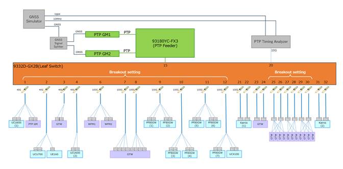
To simulate large-scale broadcast production, multiple broadcast devices were connected to the Leaf switch to verify the stability of PTP communication.
● 67 nodes of broadcast devices were connected to the Leaf switch
The test was conducted under the following conditions.
● KAIROS2 receives 64 video streams and 64 audio streams.
● Observe the video and audio streams being received by KAIROS, Waveform Monitor.
● Time error value was measured with PTP Timing Analyzer.
| Test Case |
Result |
| Under regular conditions |
● Time error was within appropriate range.
● No distortion was detected in the video and audio streams.
|
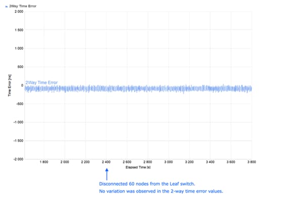
| Removing 60 nodes from the Leaf switch |
● Time error remained stable and within the appropriate range.
● No distortion was detected in the video and audio streams.
|
| Inserting the 60 nodes removed to the Leaf switch |
● Time error remained stable and within the appropriate range.
● No distortion was detected in the video and audio streams.
|
| Monitoring for 12 hours under regular conditions |
● Time error remained stable and within the appropriate range.
|
For associated Design Guides and Solution Guides, refer to the following documents:
Cisco IP Fabric for Media Design Guide
https://www.cisco.com/c/en/us/td/docs/dcn/whitepapers/cisco-ipfm-design-guide.html
Cisco Nexus 9000 Series NX-OS IP Fabric for Media Solution Guide
Precision Time Protocol for Timing in IP Fabric for Media Guide
Cisco and the Cisco logo are trademarks or registered trademarks of Cisco and/or its affiliates in the U.S. and other countries. To view a list of Cisco trademarks, go to this URL: www.cisco.com/go/trademarks. Third-party trademarks mentioned are the property of their respective owners. The use of the word partner does not imply a partnership relationship between Cisco and any other company. (1721R)
Any Internet Protocol (IP) addresses and phone numbers used in this document are not intended to be actual addresses and phone numbers. Any examples, command display output, network topology diagrams, and other figures included in the document are shown for illustrative purposes only. Any use of actual IP addresses or phone numbers in illustrative content is unintentional and coincidental.
© 2026 Cisco Systems, Inc. All rights reserved.
N9K# copp copy profile strict prefix pmn
Modify the class that includes PTP and increase the CIR as follows.
N9K(config)# policy-map type control-plane pmn-copp-policy-strict
N9K(config-pmap)# class pmn-copp-class-redirect
N9K(config-pmap-c)# police cir 1500 kbps bc 128000 bytes conform transmit violate drop