Physical Management Cluster Operations and Deployment Guide for Stack Automation by Quali
Available Languages
Bias-Free Language
The documentation set for this product strives to use bias-free language. For the purposes of this documentation set, bias-free is defined as language that does not imply discrimination based on age, disability, gender, racial identity, ethnic identity, sexual orientation, socioeconomic status, and intersectionality. Exceptions may be present in the documentation due to language that is hardcoded in the user interfaces of the product software, language used based on RFP documentation, or language that is used by a referenced third-party product. Learn more about how Cisco is using Inclusive Language.
- US/Canada 800-553-2447
- Worldwide Support Phone Numbers
- All Tools
 Feedback
 Feedback
Management cluster architecture and deployment models
The Cisco Stack Automation management cluster is a dedicated set of Cisco UCS rack servers and two Cisco Nexus switches. It runs the software that plans, deploys, and operates customer PODs. It hosts four applications:
• Cisco Intersight Connected Virtual Appliance (CVA)
• Cisco Nexus Dashboard
• Stack Automation management cell
• NetBox
You deploy the cluster in one of two models. Select the model during planning in Stack Automation; the bill of materials and switch configuration bundles follow from that choice.
Deployment models
| Deployment model |
Single server |
Three servers (high availability) |
| UCS rack servers |
1 |
3 |
| Nexus 93108TC-FX3P switches |
2 |
2 |
| Survives a server failure |
No |
Yes. The cluster virtual IP stays up while two servers run |
| Typical use |
Lab, proof of concept, small site |
Production |
| Setup on the console |
Create on server 1 |
Create on server 1, then join on servers 2 and 3 |
| Approximate console time |
20 minutes |
About 20 minutes for server 1, plus the join on each added server |
Management cluster deployment workflow
A deployment moves through ten tasks, from the plan in Stack Automation to a verified cluster. Tasks 7 and 8 build the cluster; everything before them prepares the network and servers.
Deployment tasks
| Task |
What you do |
Where |
Applies to |
| 1 |
Plan the cluster and order the hardware |
Stack Automation portal |
All |
| 2 |
Prepare the site and complete the IP planning worksheet |
Site |
All |
| 3 |
Rack and cable the switches and servers |
Data center |
All |
| 4 |
Apply the configuration bundles to both Nexus switches |
Switch console |
All |
| 5 |
Set a static CIMC IP address on each server |
Server console (F8) |
All |
| 6 |
Claim server 1 to Intersight |
Intersight |
Server 1 |
| 7 |
Register the management server and get the token |
Stack Automation portal |
All |
| 8 |
Create the cluster |
Server 1 console (CIMC KVM) |
All |
| 9 |
Join the remaining servers |
Server 2 and 3 consoles |
Three servers only |
| 10 |
Verify the deployment and server claims |
Portal, console, Intersight |
All |
Two roles usually share the work: a Stack Automation administrator (tasks 1, 7, 10) and a field engineer at the hardware (tasks 2 to 6, 8, 9).
Task 1: Plan the cluster and order the hardware
Create the management cluster plan in Stack Automation. The plan produces two things you use later: the bill of materials for ordering, and a configuration bundle for each Nexus switch.
Before you begin
• A Stack Automation tenant and an administrator account.
• The deployment model: single server or three servers.
• Network values for the site. Use the IP planning worksheet in Task 2.
Procedure
1. Log in to the Stack Automation portal as an administrator.
2. Open the planning phase for the management cluster and select the deployment model: one server, or three servers for high availability.
3. Enter the network values from the IP planning worksheet.
4. Review the generated bill of materials and submit the order.
5. When the order is fulfilled and the hardware ships, return to the plan and download the configuration bundles: one for switch A and one for switch B. Keep them for Task 4.
Management cluster bill of materials
| Product ID |
Description |
Single server |
Three servers |
| N9K-C93108TC-FX3P |
Nexus 9300 switch, 48 × 100M/1/2.5/5/10GBASE-T, 6 × 100G QSFP28 |
2 |
2 |
| UCS-M8-MLB |
UCS M8 rack server (management server appliance) |
1 |
3 |
The order includes the server options, power supplies, optics, and cables that the plan selects. Check the delivered items against the order before you start Task 3.
What to do next
When the hardware arrives, prepare the site (Task 2).
Prepare every address and credential before you power on the equipment. Setup checks DNS, time, and reachability to Stack Automation before it applies anything and stops on a failed check.
Site checklist
• ☐ Rack space for two 1RU switches and one or three rack servers, with power for each
• ☐ One uplink from the customer network to each Nexus switch
• ☐ A laptop with a serial console cable for the switches and a monitor and keyboard (or KVM dongle) for the servers
• ☐ The two switch configuration bundles from Task 1
• ☐ Outbound HTTPS (TCP 443) from the cluster network to stackautomation.cisco.com, direct or through a proxy
• ☐ DNS servers that resolve public names, and NTP servers if you won’t use public NTP
• ☐ Intersight account access for claiming server 1 (Task 6)
• ☐ A Stack Automation administrator available to issue the registration token (Task 7). The token is valid for 72 hours.
IP planning worksheet
All cluster addresses are in one management subnet. The example column uses documentation addresses; replace these with your own network values. The Code column identifies the setup screen where you must enter the value. If the cluster hosts Nexus Dashboard or Intersight Assist, it includes addresses, names, and administrator passwords in your plan, as the console prompts for these values during setup.
| Item |
Console screen |
Example |
Your value |
| Management subnet and prefix |
— |
192.0.2.0/24 |
|
| Default gateway |
Network |
192.0.2.1 |
|
| Switch A management IP |
— |
192.0.2.11 |
|
| Switch B management IP |
— |
192.0.2.12 |
|
| CIMC, server 1 |
— |
192.0.2.61 |
|
| CIMC, server 2 (three servers only) |
— |
192.0.2.62 |
|
| CIMC, server 3 (three servers only) |
— |
192.0.2.63 |
|
| Cluster DNS name |
Cluster |
lab-cluster.example.com |
|
| Cluster virtual IP |
Cluster |
192.0.2.70 |
|
| Server 1 host name and IP |
Network |
lab-cluster-1, 192.0.2.71/24 |
|
| Server 2 IP (three servers only) |
Join cluster |
192.0.2.72/24 |
|
| Server 3 IP (three servers only) |
Join cluster |
192.0.2.73/24 |
|
| DNS servers |
Network |
192.0.2.53, 192.0.2.54 |
|
| NTP servers (optional) |
Time |
ntp.example.com |
|
| HTTP and HTTPS proxy (optional) |
Network |
http://proxy.example.com:8080 |
|
| Proxy exceptions (optional) |
Network |
.corp.example.com, 10.0.0.0/8 |
|
| Operator password |
Operator access |
8 or more characters |
Store securely |
Note: The cluster virtual IP never changes as servers join. Point bookmarks, DNS records and integrations at the virtual IP, not at a server IP.
Task 3: Rack and cable the cluster
Cable both switches in the same way: the uplink on the first port, servers from port 2 upward, and the vPC peer-link on the last ports. Each server connects one data port to switch A and one to switch B on the same port number.
Management cluster port map
| Port (switch A and switch B) |
Connects to |
Single server |
Three servers |
| Eth1/1 (or the uplink port the plan specifies) |
Customer network uplink |
Yes |
Yes |
| Eth1/2 |
Server 1 data port (port 1 to switch A, port 2 to switch B) |
Yes |
Yes |
| Eth1/3 |
Server 2 data port |
— |
Yes |
| Eth1/4 |
Server 3 data port |
— |
Yes |
| Eth1/53–1/54 |
vPC peer-link, switch A to switch B |
Yes |
Yes |
| mgmt0 |
Switch management network |
Yes |
Yes |
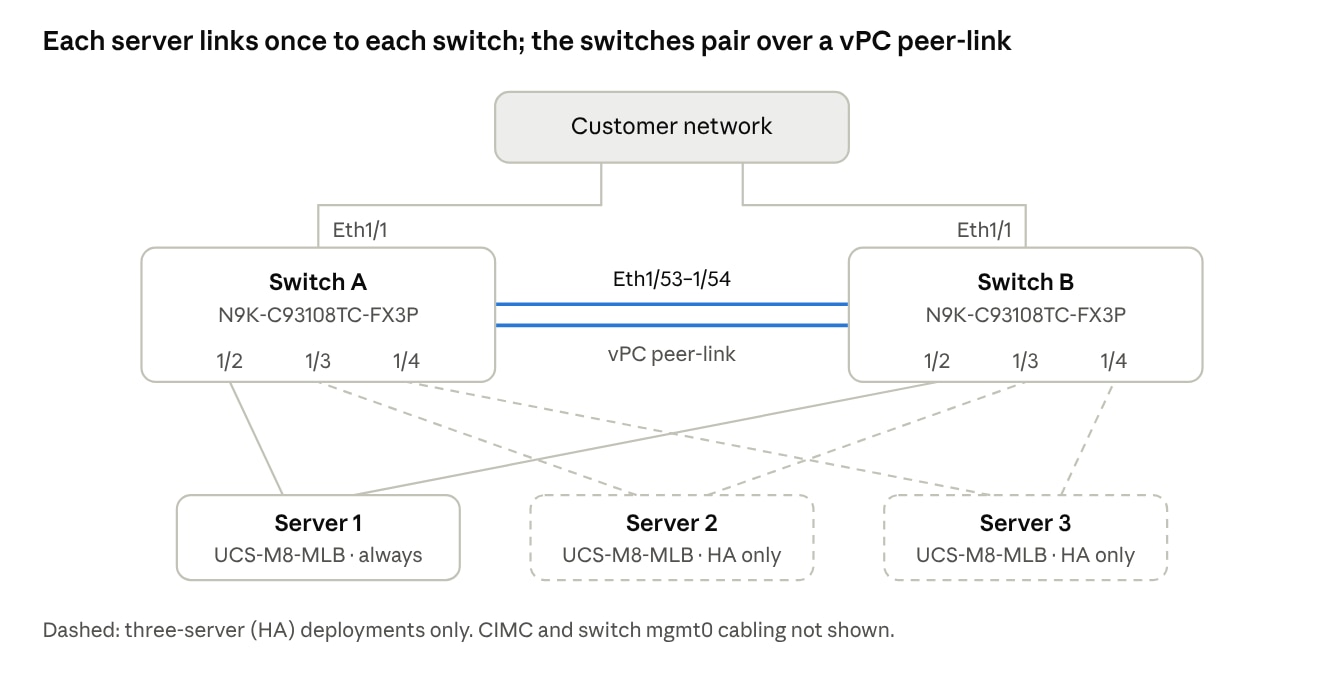
Figure 1. Management cluster cabling: 2 switches, 1 or 3 servers
Each server port 1 goes to switch A and port 2 to switch B on the same port number, so the cluster survives the loss of either switch.
Procedure
1. Rack both Nexus 93108TC-FX3P switches and label them switch A and switch B.
2. Rack the servers and label them server 1, server 2 and server 3 from the top. Server 1 is the one you create the cluster on.
3. Connect the vPC peer-link: Eth1/53 on switch A to Eth1/53 on switch B, and Eth1/54 to Eth1/54.
4. Connect each server’s two data ports to the same port number on switch A and switch B, as the port map shows.
5. Connect the uplink on each switch to the customer network.
6. Connect power. Don’t power on the servers yet.
Note: The Network -- adapter screen displays the status of each network adapter. If both data ports show a link, the system bonds the two ports. If a port shows no link, verify the cable connection to the peer switch before you proceed.
What to do next
Apply the configuration bundles to the switches (Task 4).
Task 4: Configure the Nexus switches
Stack Automation generates one configuration bundle per switch from your plan. Paste each bundle into its corresponding switch from the serial console. The bundle sets the management address, VLANs, vPC domain and peer-link, the server-facing ports, and the uplink.
Before you begin
• Switches racked, cabled and powered (Task 3).
• The configuration bundles for switch A and switch B (Task 1).
• A serial console session: 9600 baud, 8 data bits, no parity, 1 stop bit.
Procedure
Complete steps 1 to 6 on switch A and then repeat the steps on switch B with the corresponding bundle.
1. Connect to the switch console port and power on the switch.
2. When the Power On Auto Provisioning (POAP) prompt appears, enter skip. This bypasses POAP, the admin password prompt and the basic configuration dialog.
Abort Power On Auto Provisioning [yes - continue with normal setup,
skip - bypass password and basic configuration, no - continue with
Power On Auto Provisioning] (yes/skip/no)[no]: skip
3. The switch boots to the switch# prompt with no login. Enter configuration mode:
switch# configure terminal
4. Open the bundle for this switch in a text editor, copy all of it and paste it into the console. Wait for the prompt to return.
5. Leave configuration mode and save:
switch(config)# end
switch# copy running-config startup-config
6. Confirm you can log in with the admin account that the bundle created.
7. After both switches are configured, verify from either switch:
| Command |
Expected result |
| show vpc |
Peer status: peer adjacency formed ok. vPC keep-alive status: peer is alive |
| show port-channel summary |
Peer-link port channel up (P flag) on Eth1/53–1/54 |
| show interface status |
Uplink connected. Server ports connected once the servers are powered on |
| show vlan brief |
The management VLAN from the plan is active on the server ports |
| ping <gateway> |
Replies from the default gateway |
Caution: Paste each bundle into the switch it was generated for. The switch A and switch B bundles differ in addresses and vPC role.
What to do next
Power on the servers and set the CIMC addresses (Task 5). A sample bundle is in Appendix C.
Task 5: Configure a static CIMC IP address on each server
Configure a static IP address for each server’s Cisco Integrated Management Controller (CIMC). You use CIMC for the remote KVM console in Tasks 8 and 9, and Intersight reaches the servers through it.
Before you begin
• A monitor and keyboard (or KVM dongle) connected to the server.
• The CIMC addresses from the IP planning worksheet.
Procedure
Complete this procedure on each server.
1. Power on the server.
2. When the Cisco logo appears, press F8 to open the CIMC Configuration Utility.
3. If prompted, change the default CIMC password. Use the password your site standard requires.
4. Under NIC mode, select the mode that matches your CIMC cabling (Task 3). Set NIC redundancy to match.
5. Under IP (Basic), uncheck DHCP enabled and enter these values:
– CIMC IP: the server’s CIMC address, for example 192.0.2.61
– Prefix/Subnet: for example, 255.255.255.0
– Gateway: the default gateway
6. Leave VLAN disabled unless your plan specifies one.
7. Press F10 to save, wait for the settings to apply, then press Esc to exit. The server continues to boot.
8. From your laptop, open https://
Note: Leave the servers powered on after this task. New appliances ship with the management server software installed and boot to the first setup screen. You only need the ISO if a server must be re-imaged (Task 7).
What to do next
Claim server 1 to Intersight (Task 6).
Task 6: Claim server 1 in Cisco Intersight
Manually claim only server 1. After the cluster is up, the management server claims the remaining servers itself (Task 10).
Before you begin
• CIMC on server 1 is reachable (Task 5).
• CIMC has DNS and outbound HTTPS, directly or through a proxy.
• An Intersight account with permission to claim targets.
Procedure
1. Log in to the server 1 CIMC web interface.
2. Choose Admin > Device Connector. Check that the connector status shows it can reach Intersight. If you use a proxy, configure it under Settings.
3. Copy the Device ID and Claim Code.
4. In Intersight, choose System > Targets, and then click Claim a New Target.
5. Select Cisco UCS Server (Standalone) and click Start.
6. Paste the Device ID and Claim Code and click Claim.
7. Confirm that server 1 appears under Targets with status Connected.
Caution: Don’t claim servers 2 and 3 by hand. A manual claim conflicts with the claim the management server makes later.
What to do next
Register the management server in the Stack Automation portal (Task 7).
Task 7: Register the management server in Stack Automation
A Stack Automation administrator creates a Physical management server entry in the portal. The entry generates a registration token. In Task 8, the field engineer enters it on server 1, in the console’s External ID field, and confirms the Stack Automation address.
Before you begin
• A Stack Automation administrator account.
• The name you’ll use for this management server in the portal, for example dc-west.
Procedure
1. In the Stack Automation portal, go to Management Servers and click + New Management Server.
2. On Setup, under Where will the management server run? select On-Premises. Under What type? select Physical (Cisco appliance, 1 or 3 servers). Click Next.
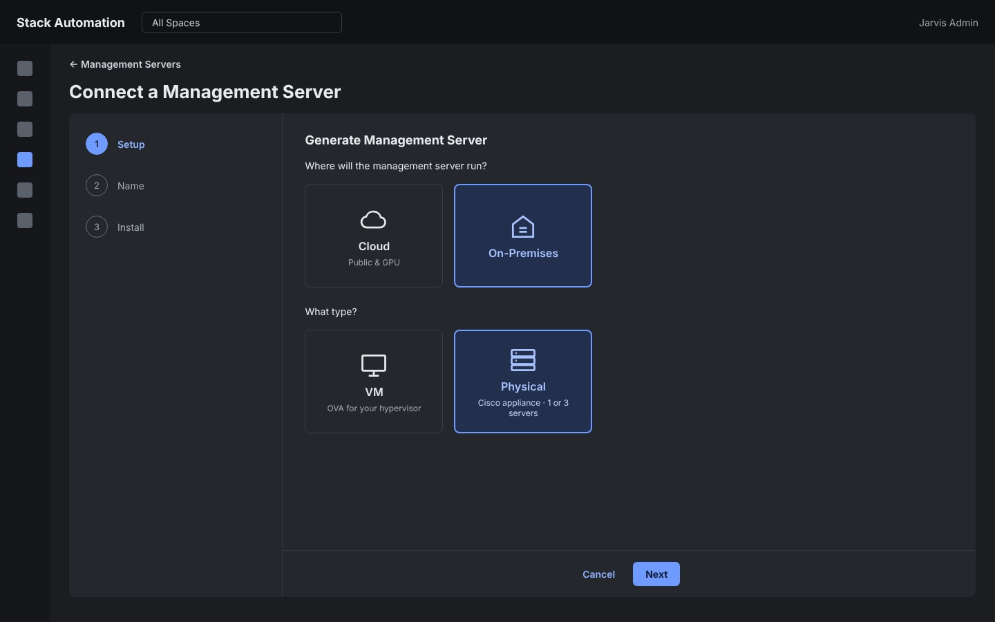
Figure 2. Connect a Management Server, Setup step: On-Premises and Physical selected
3. On Name, enter a name for the management server and click Next.
4. On Install, copy the Registration token, or click Email to engineer to send it to the person at the servers.
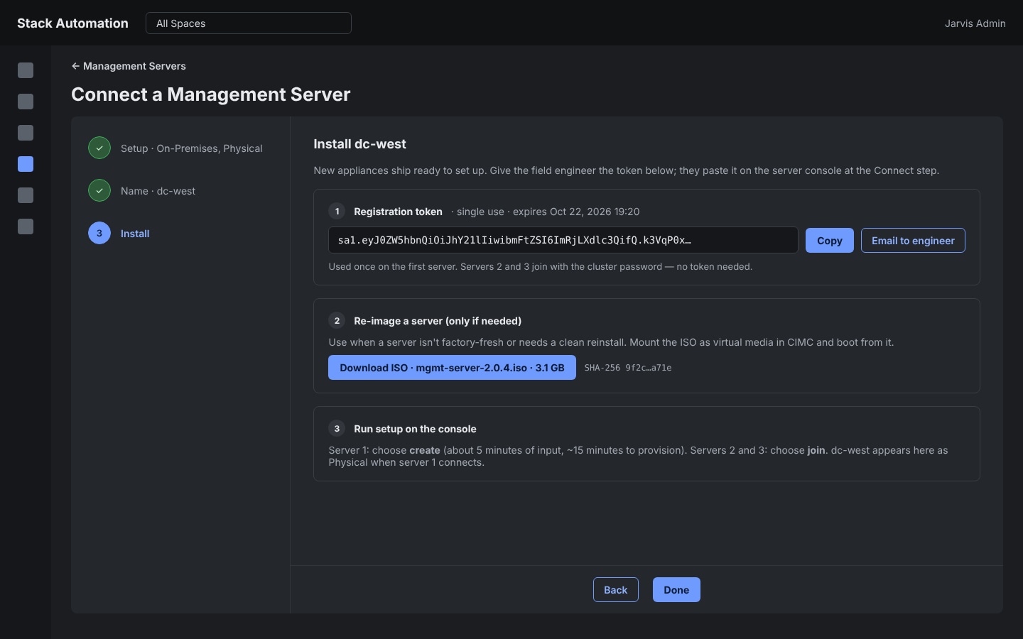
Figure 3. Connect a Management Server, Install step: registration token, optional ISO and console instructions
5. Click Done. The entry appears in the Management Servers list as Awaiting setup with the days left on its token.
| Install step item |
Purpose |
| 1 Registration token |
Single use, valid 72 hours. Used once, on server 1 only. Servers 2 and 3 join with the cluster’s operator password and need no token. |
| 2 Re-image a server (only if needed) |
Download mgmt-server-2.0.4.iso (3.1 GB) and check its SHA-256. Use it only if a server isn’t factory-fresh: mount it as CIMC virtual media and boot from it. |
| 3 Run setup on the console |
Server 1: select create (about 10 minutes of input, then about 10 to 15 minutes of unattended setup). Servers 2 and 3: select address to join the cluster. |
Note: Each entry has one active token. If the token expires before setup, open the entry’s menu in the Management Servers list and select Download registration token. The new token replaces the old one.
What to do next
Create the cluster on server 1 (Task 8).
Task 8: Create the cluster on server 1
Setup on server 1 is a sequence of short screens that each ask for one value: about 10 minutes of input, then about 10 to 15 minutes of unattended setup (longer when the cluster hosts Nexus Dashboard or Intersight Assist). Each screen shows its name in the title of its box; quote it when you contact support. The bottom line of every screen shows the installed image and update versions. The figures show a sample network; your addresses differ.
Before you begin
• Server 1 is powered on and its CIMC is reachable (Task 5).
• The completed IP planning worksheet (Task 2).
• The registration token from Task 7, less than 72 hours old. The console calls it the External ID.
Console navigation keys
| Key |
Action |
| Tab |
Move between the entry field, choices, and buttons. On a screen with scrolling text, Tab moves from the text to the choices |
| ↑ ↓ |
Move between choices, or scroll the text |
| Enter |
Select the highlighted choice or button (Next, Select, Ok) |
| <Back> |
Return to the previous screen |
| Show/Hide |
On a hidden field such as External ID, show or hide the value you entered |
| q, r, d |
On the status screen: back to the menu, refresh, technical details |
Procedure
1. Open the server 1 console. Log in to CIMC at https://<CIMC IP> and launch the KVM console. You can also use a local monitor and keyboard.
2. On new or existing cluster, select create (Create a new cluster) and select Next.
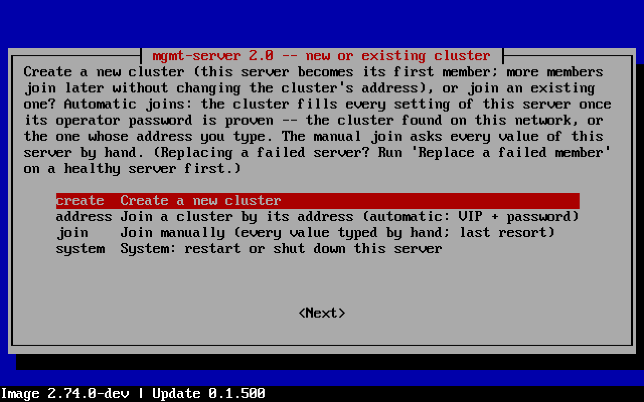
Figure 4. New or existing cluster
3. On Network -- adapter, check that both data ports show link up. When exactly two identical ports have a link, the console proposes a bond of the two (active-backup). Press Tab to move to the choices, keep bond and select Next.
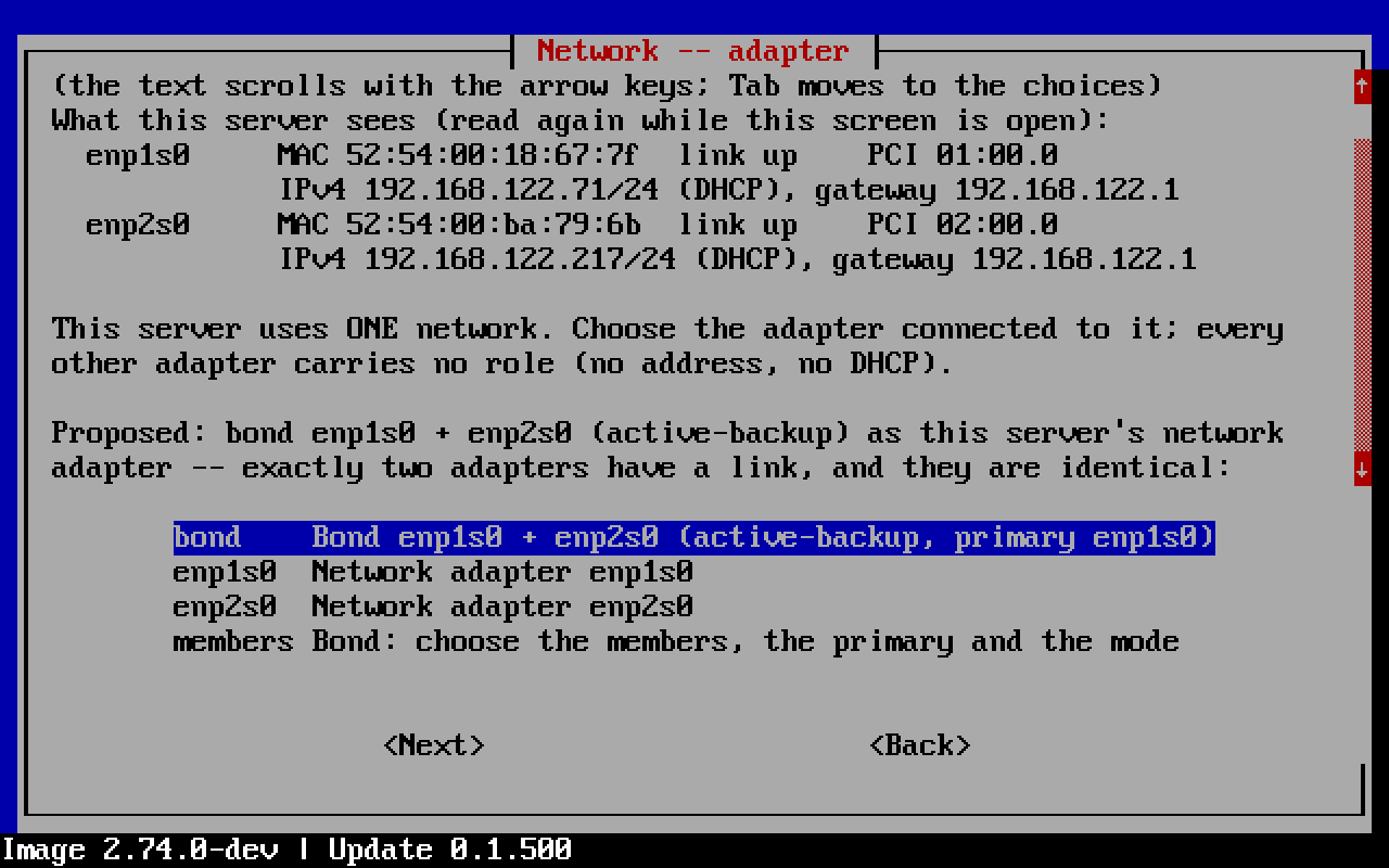
Figure 5. Network adapter
4. On the Network, Network -- proxy and Time screens, enter one value per screen and select Next after each. When a DHCP server answers on the network, the console offers its values for the prefix, gateway, and DNS servers; edit them if needed.
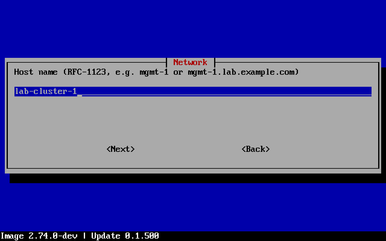
Figure 6. Network, host name
| Field |
Description |
Default |
| Host name |
This server’s name: letters, digits, and hyphens. Example: lab-cluster-1 |
--- |
| IP address |
This server’s IPv4 address. Use a static address, not an address a DHCP server leased |
--- |
| Prefix length |
0 to 32 |
From DHCP, when offered |
| Gateway |
Required |
From DHCP, when offered |
| DNS servers |
Optional, comma-separated |
From DHCP, when offered |
| HTTP proxy, HTTPS proxy |
Optional, one screen each. Example: http://proxy.example.com:8080 |
Blank: no proxy |
| Addresses reached without the proxy |
Optional, comma-separated. Example: .example.com,10.0.0.0/8 |
Blank |
| Upstream NTP servers |
Optional, comma-separated. The server always serves time to its network; an upstream server keeps the time accurate |
Blank |
| Allow public time servers |
Yes adds time.cloudflare.com, nts.netnod.se, ptbtime1.ptb.de and time.nist.gov to your servers. Select it only where the site allows Internet use |
No |
5. On Network check, the console automatically tests the address, link, route, gateway, DNS, and time from this server. When the screen shows Every check passed, select Next. If a check fails, the screen identifies it; go back and correct the value.
6. On StackAutomation, confirm the endpoint URL (https://stackautomation.cisco.com by default) and select Next. Then enter the registration token from Task 7 in the External ID field. The value is hidden as you enter it; Show/Hide shows it. Select Next.
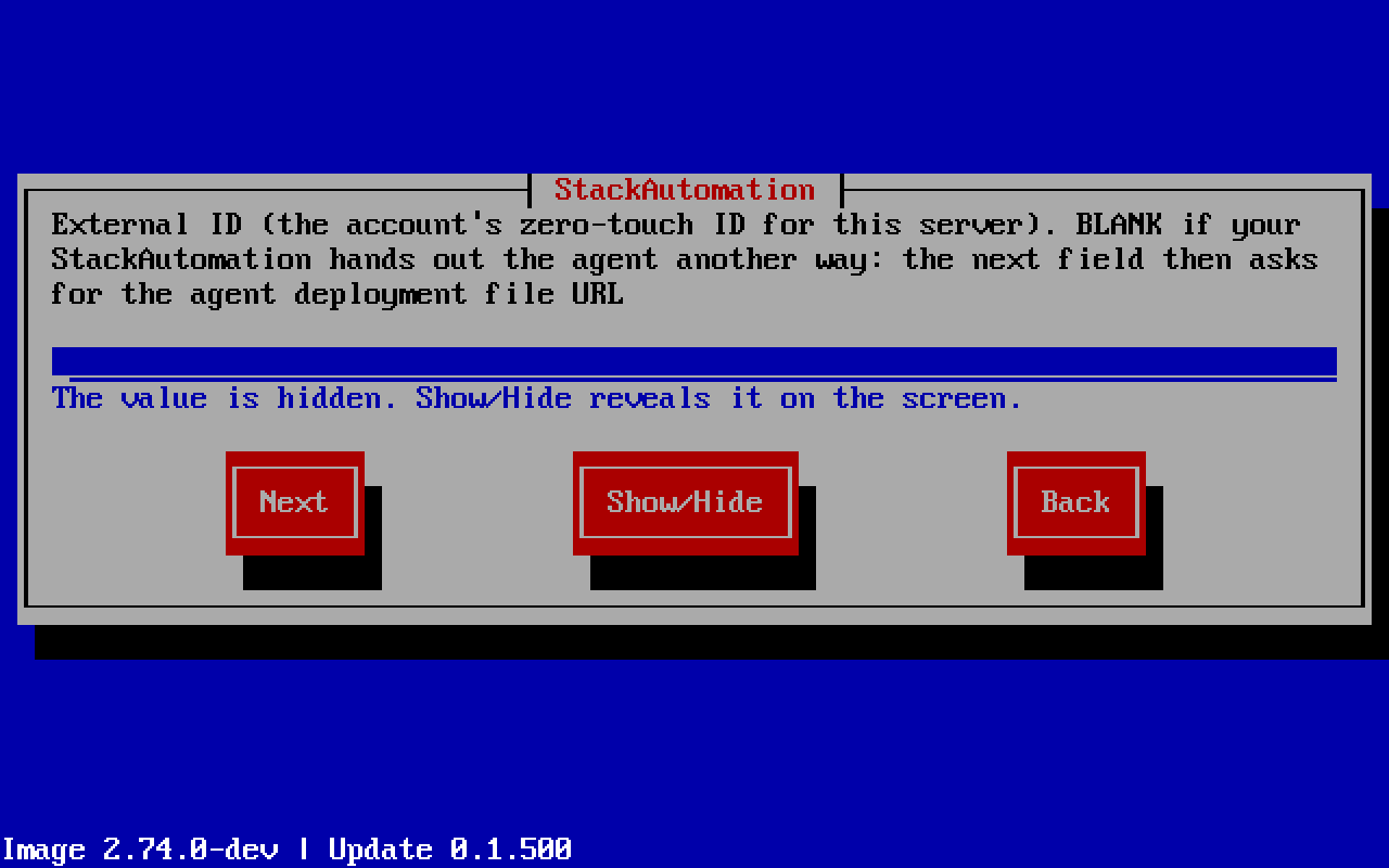
Figure 7. StackAutomation, External ID
7. On Cluster -- new cluster, enter the Cluster VIP: an unused address in this server’s subnet, which stays the same as members join. Select Next. Then enter the Cluster DNS name, the name clients use for the cluster and select Next.
8. On Appliances -- Nexus Dashboard and Appliances -- Intersight Assist, select yes or no for each, as your plan requires. Both are on by default. After yes, the console asks for the appliance’s addresses, name, and admin password.
9. On Cluster -- DHCP for joining servers, select on or off. On: the cluster’s DHCP service gives servers 2 and 3 an address while they are set up and tells them where the cluster is; it also gives an address to any other device on this network that asks. Off: you type the cluster VIP on servers 2 and 3.
10. On Operator access, enter a console password for the account operator (at least 8 characters), then enter it again to confirm. The console asks for this password before protected actions, and you enter it again on servers 2 and 3. On Operator access -- SSH key (optional), enter an SSH public key for operator, or leave the field blank. SSH accepts keys only, never a password.
11. On Review, the console runs every check again and lists all values; use the Up Arrow and Down Arrow keys to scroll. When it shows every check passed -- ready to apply, press Tab, select apply and press Enter. To change a value, select Back. recheck runs the checks again and details shows the result of each check.
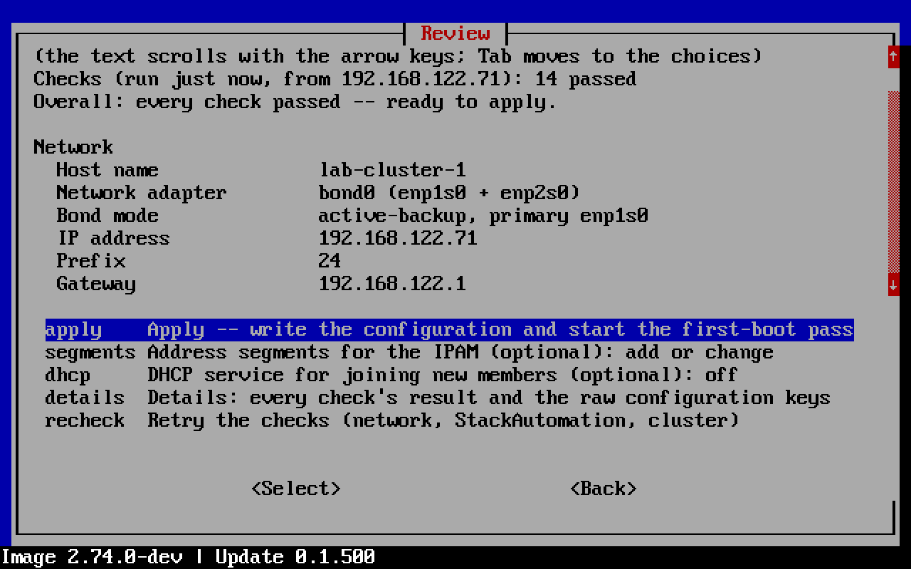
Figure 8. Review
12. The status screen shows the setup progress and refreshes automatically. Wait until every stage is complete, about 10 to 15 minutes. You do not need to keep the console open while setup runs.
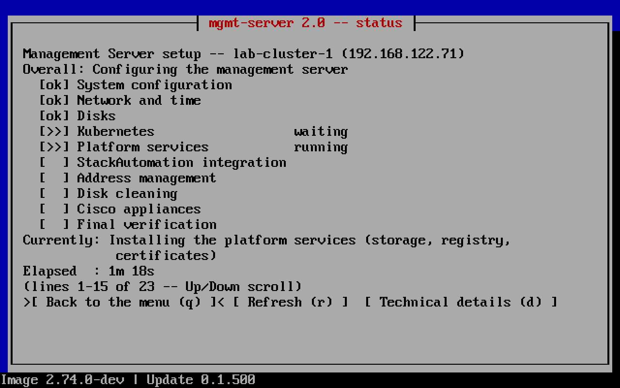
Figure 9. Status, setup in progress
| Setup stage |
Meaning |
| System configuration |
The values you entered are written |
| Network and time |
The network, host name, and time are configured |
| Disks |
The server’s disks are prepared |
| Kubernetes |
The cluster software starts |
| Platform services |
Storage, the registry, certificates, the file service, DNS, and the download caches are installed |
| StackAutomation integration |
The Stack Automation agent is installed and connects |
| Address management |
The address management service (IPAM) starts |
| Disk cleaning |
The disk cleaning service is set up |
| Cisco appliances |
Nexus Dashboard and Intersight Assist are created when you select them |
| Final verification |
The server verifies its own setup |
13. When setup finishes, the status screen shows Status: Ready; Cluster: 1 member, Ready; and StackAutomation: Connected. Press q to open the main menu.
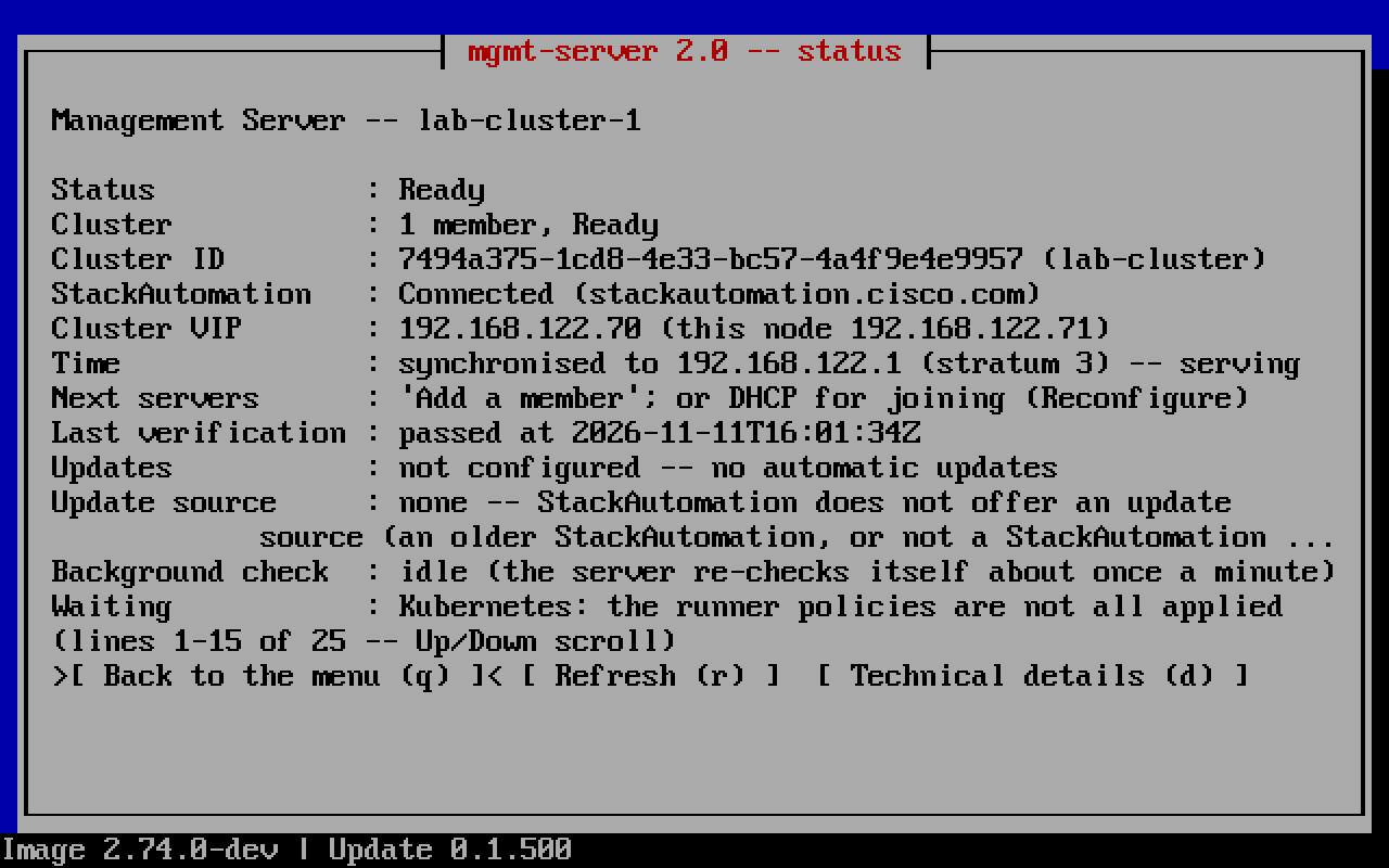
Figure 10. Status, Ready
Note: If a stage fails, the status screen shows Retrying with the stage and the last problem, and the server retries automatically. Refer to Troubleshoot management server setup. Your settings are kept.
What to do next
• Single server: verify the deployment (Task 10).
• Three servers: join servers 2 and 3 (Task 9). Have the cluster VIP and the operator password ready.
For three-server deployments, each remaining server joins from its own console: you enter the cluster VIP and the cluster’s operator password. The console displays a proposed server address and host name, and the cluster supplies every other setting. You do not need a registration token.
Before you begin
• Server 1 shows Status: Ready (Task 8).
• Servers 2 and 3 are powered on, with CIMC reachable (Task 5).
• The cluster VIP and the operator password, and the planned IP address of each server to check against the address the cluster proposes.
Procedure
Join server 2 first, then server 3.
1. Open the server console through the CIMC KVM.
2. On new or existing cluster, select address (Join a cluster by its address) and select Next.
3. On Join a cluster by its address, enter the cluster VIP and select Next.
4. On Join cluster, check the proposed address and host name against your worksheet. Select join to accept them, or address or name to change one.
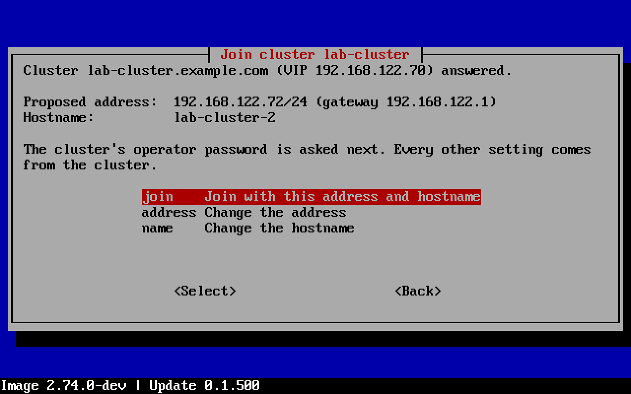
Figure 11. Join cluster, proposed address and host name
| Field |
Description |
| Cluster VIP |
The cluster VIP set on server 1. You can also use any member’s address |
| Proposed address |
This server’s address, proposed by the cluster in the same subnet. Example: 192.0.2.72/24 |
| Operator password |
The operator password set on server 1. It becomes this server’s console password too |
The gateway, DNS, time, proxy and Stack Automation connection come from the cluster. On server 1, Add a member to this cluster in the main menu shows the values to enter on the new server and the current members.
5. On Join cluster -- operator password, enter the cluster’s operator password and select Next. The password is proven to the cluster without being sent.
6. The server joins the cluster, and the status screen shows its setup progress. Wait until it shows Status: Ready.
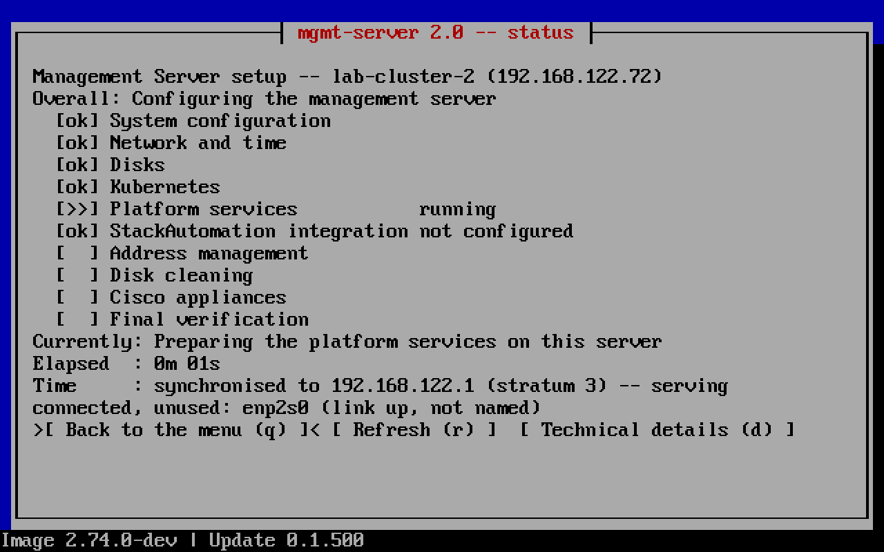
Figure 12. Status on a joining server
7. Repeat steps 1 to 6 on server 3.
Note: The cluster virtual IP stays on the same address as members join. Users and integrations aren’t interrupted.
What to do next
Verify the deployment (Task 10).
Task 10: Verify the deployment
The deployment is complete when the portal shows the cluster as Physical and connected, every member shows Ready on the console, and every server is claimed in Intersight.
Procedure
1. In the Stack Automation portal, go to Management Servers. Confirm that your entry changed from Awaiting setup to Connected, with type Physical, the virtual IP, and its members nested under it.
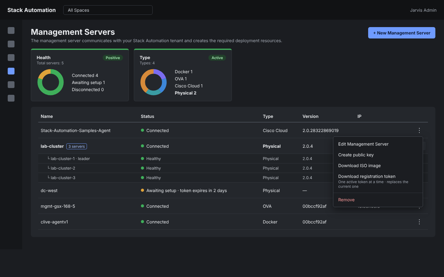
Figure 13. Management Servers list with a three-server Physical cluster and an entry awaiting setup
2. On any server console, open the main menu and select status. The header of the main menu summarizes the same state. Check:
– Status reads Ready.
– Cluster shows every member Ready: 1 member, or 3 members.
– Time reads synchronized and StackAutomation reads Connected.
– The adapter line shows link up for both ports of the bond.
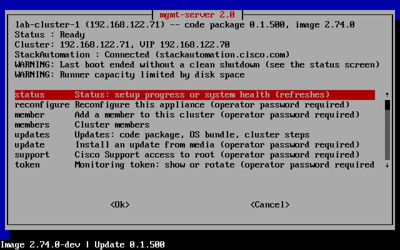
Figure 14. Main menu on a cluster member
3. In Intersight, confirm that every server is claimed. Server 1 was claimed in Task 6. The management server claims servers 2 and 3 once the cluster is up; no manual step is needed.
4. Optional: on the status screen, press d for the technical details: addresses, members, versions, and the state of each setup step.
| Check |
Where |
Expected result |
| Cluster status |
Portal, Management Servers |
Connected, type Physical, virtual IP shown |
| Members |
Portal and console status screen |
All members Ready |
| Time and connection |
Console status screen |
Time synchronized; StackAutomation Connected |
| Links |
Console status screen |
Both ports of the bond show link up on every server |
| Server claims |
Intersight, Targets |
All servers claimed and Connected |
What to do next
The management cluster is ready. Continue in Stack Automation to onboard your first POD.
Troubleshoot management server setup
If a setup stage fails, the status screen shows Retrying with the stage, the attempt number and the time of the failure. The server retains the values you entered and retries automatically within about a minute of each failure. Scroll down to Last problem to read what failed.
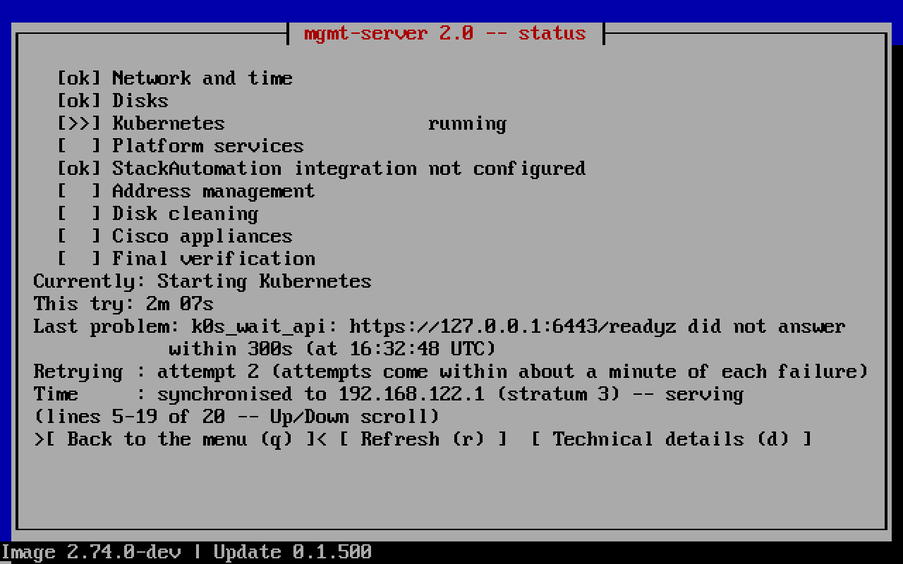
Figure 15. Status, setup retrying after a problem
| Option |
What it does |
| Refresh (r) |
Refresh the status. The screen also refreshes automatically |
| Technical details (d) |
Show the addresses, members, versions, the state of each setup step and the failure text, for support |
| Back to the menu (q) |
Open the main menu |
| reconfigure (main menu) |
Change the settings you entered. Asks for the operator password |
| system (main menu) |
Restart or shut down the server. Asks for the operator password |
Common management server setup problems
| Symptom |
Likely cause |
Fix |
| The External ID is not recognized |
The registration token was mistyped, expired (72 hours) or was already used |
In the portal, open the entry’s menu and select Download registration token. On the console, enter the new value in External ID |
| Network -- adapter shows no link on a port |
A data cable is missing, or a switch port is down |
Check the cable to Eth1/2–1/4 on both switches. Run show interface status and confirm the bundle was applied |
| Network check fails: gateway, DNS or address |
A wrong address, prefix, gateway or DNS server, or the address is already in use |
Go back and correct the value on its screen |
| Network check fails: time |
NTP servers unreachable |
Enter reachable NTP servers, or allow the public time servers |
| Review check fails: Stack Automation not reachable |
No route, DNS or proxy for stackautomation.cisco.com:443 |
Check the gateway and DNS. If outbound traffic needs a proxy, go back and set the HTTP and HTTPS proxy. Select recheck |
| Join: the cluster does not answer |
Wrong cluster VIP, or the server is in another subnet |
Use the cluster VIP that the status screen of server 1 shows |
| Join: the operator password is not accepted |
The password doesn’t match the one set on server 1 |
Enter the operator password set on server 1 |
| CIMC not reachable after F8 |
Wrong NIC mode, IP, gateway, or cabling |
Re-enter the CIMC Configuration Utility (F8) and check the values |
| show vpc shows the peer link down |
Peer-link cables, or the bundles applied to the wrong switches |
Check the Eth1/53–1/54 cables. Confirm each switch has its own bundle |
| A server isn’t claimed in Intersight |
The automatic claim hasn’t finished, or server 1 was not claimed first |
Wait for the cluster to finish, then check the claim of server 1 (Task 6) |
Appendix A: Console main menu
After setup, the console shows the main menu. Its header shows the server’s name and address, the installed versions, the status, the cluster members and VIP, and the Stack Automation connection. Items labeled operator password required ask for the password first.
| Menu option |
What it does |
| status |
Setup progress or system health. Refreshes automatically |
| reconfigure |
Change this server’s settings (operator password required) |
| member |
Add a member to this cluster: shows the values to enter on the new server (operator password required) |
| members |
List the cluster members with address, role and state |
| updates |
Show the installed code package and OS bundle, and the update steps |
| update |
Install an update from media (operator password required) |
| support |
Cisco Support access (operator password required) |
| token |
Show or rotate the monitoring token (operator password required) |
| system |
Restart, shut down, connection (operator password required) |
| login |
Leave to a login prompt |
Additional items appear when applicable. For example, replace (Replace a failed member) on a cluster of three or more servers.
On a server that isn’t set up yet, the system option on the first screen restarts or shuts down the server.
Appendix B: Field reference
| Field |
Screen |
Rule or default |
| Host name |
Network |
Letters, digits, and hyphens |
| IP address |
Network |
This server’s static IPv4 address |
| Prefix length |
Network |
0 to 32 |
| Gateway |
Network |
Required |
| DNS servers |
Network |
Optional, comma-separated |
| HTTP proxy, HTTPS proxy |
Network -- proxy |
Optional. Blank means no proxy |
| Addresses reached without the proxy |
Network -- proxy |
Optional, comma-separated |
| Upstream NTP servers |
Time -- NTP servers |
Optional, comma-separated |
| Public time servers |
Time -- public time servers |
Default: no |
| Endpoint URL |
StackAutomation |
HTTPS only. Default: https://stackautomation.cisco.com |
| External ID |
StackAutomation |
The registration token from the Stack Automation administrator (Task 7) |
| Cluster VIP |
Cluster -- new cluster; Join a cluster by its address |
An unused address in the server’s subnet. Stays the same as members join |
| Cluster DNS name |
Cluster -- new cluster |
Required. The name clients use for the cluster |
| Operator password |
Operator access; Join cluster |
8 or more characters. Set on server 1, entered again on servers 2 and 3 |
| SSH public key |
Operator access -- SSH key |
Optional, single line |
Appendix C: Sample switch configuration bundle
The sample bundle is a placeholder that shows the structure of the switch A configuration for a three-server cluster. The real bundle comes from the Stack Automation plan.
! SAMPLE ONLY - switch A (N9K-C93108TC-FX3P), three-server cluster
hostname mgmt-sw-a
feature lacp
feature vpc
feature lldp
username admin password <from plan> role network-admin
interface mgmt0
vrf member management
ip address 192.0.2.11/24
vrf context management
ip route 0.0.0.0/0 192.0.2.1
vlan 10
name mgmt-cluster
vpc domain 10
role priority 10
peer-keepalive destination 192.0.2.12 source 192.0.2.11 vrf management
interface port-channel100
description vPC peer-link
switchport mode trunk
vpc peer-link
interface Ethernet1/53-54
description vPC peer-link to mgmt-sw-b
switchport mode trunk
channel-group 100 mode active
no shutdown
interface Ethernet1/1
description Uplink to customer network
switchport mode trunk
switchport trunk allowed vlan 10
no shutdown
interface Ethernet1/2
description server-1 port 1
switchport access vlan 10
spanning-tree port type edge
no shutdown
interface Ethernet1/3
description server-2 port 1
switchport access vlan 10
spanning-tree port type edge
no shutdown
interface Ethernet1/4
description server-3 port 1
switchport access vlan 10
spanning-tree port type edge
no shutdown
Appendix D: Screen index
| Where |
Screen |
Task |
Figure |
| Portal |
Connect a Management Server: Setup |
7 |
2 |
| Portal |
Connect a Management Server: Install |
7 |
3 |
| Console |
New or existing cluster |
8, 9 |
4 |
| Console |
Network -- adapter |
8 |
5 |
| Console |
Network, Network -- proxy, Time |
8 |
6 |
| Console |
Network check |
8 |
--- |
| Console |
StackAutomation |
8 |
7 |
| Console |
Cluster -- new cluster |
8 |
--- |
| Console |
Appliances |
8 |
--- |
| Console |
Cluster -- DHCP for joining servers |
8 |
--- |
| Console |
Operator access |
8 |
--- |
| Console |
Review |
8 |
8 |
| Console |
Status |
8, 9, 10, Troubleshoot management server setup |
9, 10, 12, 15 |
| Console |
Join a cluster by its address, Join cluster |
9 |
11 |
| Portal |
Management Servers list |
10 |
13 |
| Console |
Main menu |
10, Appendix A |
14 |
References
• Cisco APIC Getting Started Guide, Release 6.1(x): Initial Setup, the structural model for this guide
• Management Server 2.0 bootstrap design handoff, 2026-10-20 (portal screens, release 2.0.4 mockups)
Legal information
Cisco and the Cisco logo are trademarks or registered trademarks of Cisco and/or its affiliates in the U.S. and other countries. To view a list of Cisco trademarks, go to this URL: www.cisco.com/go/trademarks. Third-party trademarks mentioned are the property of their respective owners. The use of the word partner does not imply a partnership relationship between Cisco and any other company. (1110R)
Any Internet Protocol (IP) addresses and phone numbers used in this document are not intended to be actual addresses and phone numbers. Any examples, command display output, network topology diagrams, and other figures included in the document are shown for illustrative purposes only. Any use of actual IP addresses or phone numbers in illustrative content is unintentional and coincidental.
© 2026 Cisco Systems, Inc. All rights reserved.
