Licensing Requirements
See the Cisco NX-OS Licensing Guide and Cisco NX-OS Licensing Options Guide for Cisco NX-OS licensing recommendations and instructions to obtain and apply licenses.
The documentation set for this product strives to use bias-free language. For the purposes of this documentation set, bias-free is defined as language that does not imply discrimination based on age, disability, gender, racial identity, ethnic identity, sexual orientation, socioeconomic status, and intersectionality. Exceptions may be present in the documentation due to language that is hardcoded in the user interfaces of the product software, language used based on RFP documentation, or language that is used by a referenced third-party product. Learn more about how Cisco is using Inclusive Language.
This chapter describes the multicast features of Cisco NX-OS.
See the Cisco NX-OS Licensing Guide and Cisco NX-OS Licensing Options Guide for Cisco NX-OS licensing recommendations and instructions to obtain and apply licenses.
See the Nexus Switch Platform Support Matrix to know from which Cisco NX-OS releases various Cisco Nexus 9000 and 3000 switches support a selected feature.
IP multicast is a method of forwarding the same set of IP packets to a number of hosts within a network. You can use multicast in IPv4 networks to provide efficient delivery of data to multiple destinations.
 Note |
You can configure Protocol-Independent Multicast v4 (PIMv4) to run over generic routing encapsulation (GRE) tunnels including outgoing interfaces (OIF). |
Multicast involves both a method of delivery and discovery of senders and receivers of multicast data, which is transmitted on IP multicast addresses called groups. A multicast address that includes a group and source IP address is often referred to as a channel. The Internet Assigned Number Authority (IANA) has assigned 224.0.0.0 through 239.255.255.255 as IPv4 multicast addresses. For more information, see http://www.iana.org/assignments/multicast-addresses.
IPv6 multicast addresses begin with 0xFF. The IPv6 addressing architecture is defined by RFC 4291. For more information about the IANA reserved addresses, see http://www.iana.org/assignments/ipv6-multicast-addresses.
Note |
For a complete list of RFCs related to multicast, see the IETF RFCs for IP Multicast chapter. |
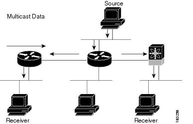
The routers in the network listen for receivers to advertise their interest in receiving multicast data from selected groups. The routers then replicate and forward the data from sources to the interested receivers. Multicast data for a group is transmitted only to those LAN segments with receivers that requested it.
This figure shows one source transmitting multicast data that is delivered to two receivers. In the figure, because the center host is on a LAN segment where no receiver requested multicast data, no data is delivered to that receiver.
A multicast distribution tree represents the path that multicast data takes between the routers that connect sources and receivers. The multicast software builds different types of trees to support different multicast methods.
A source tree represents the shortest path that the multicast traffic takes through the network from the sources that transmit to a particular multicast group to receivers that requested traffic from that same group. Because of the shortest path characteristic of a source tree, this tree is often referred to as a shortest path tree (SPT). This figure shows a source tree for group 224.1.1.1 that begins at host A and connects to hosts B and C.
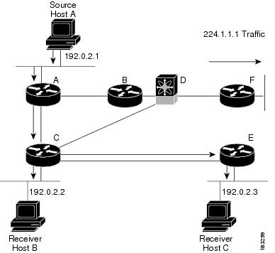
The notation (S, G) represents the multicast traffic from source S on group G. The SPT in this figure is written (192.0.2.1, 224.1.1.1). Multiple sources can be transmitting on the same group.
A shared tree represents the shared distribution path that the multicast traffic takes through the network from a shared root or rendezvous point (RP) to each receiver. (The RP creates an SPT to each source.) A shared tree is also called an RP tree (RPT). This figure shows a shared tree for group 224.2.2.2 with the RP at router D. Source hosts A and D send their data to router D, the RP, which then forwards the traffic to receiver hosts B and C.
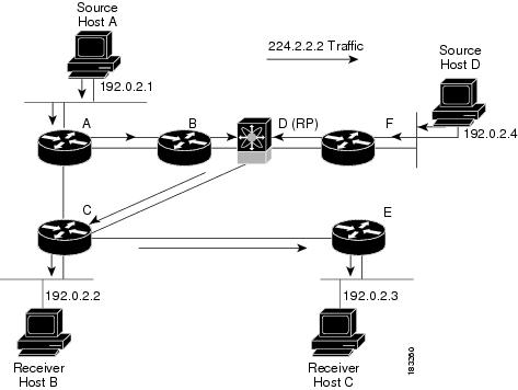
The notation (*, G) represents the multicast traffic from any source on group G. The shared tree in this figure is written (*, 224.2.2.2).
A bidirectional shared tree represents the shared distribution path that the multicast traffic takes through the network from a shared root, or rendezvous point (RP), to each receiver. Multicast data is forwarded to receivers encountered on the way to the RP. The advantage of the bidirectional shared tree is shown in the figure below. Multicast traffic flows directly from host A to host B through routers B and C. In a shared tree, the data from source host A is first sent to the RP (router D) and then forwarded to router B for delivery to host B.

The notation (*, G) represents the multicast traffic from any source on group G. The bidirectional tree in the figure is written as (*, 224.2.2.2).
Because multicast traffic is destined for an arbitrary group of hosts, the router uses reverse path forwarding (RPF) to route data to active receivers for the group. When receivers join a group, a path is formed toward the source (SSM mode) or the RP (ASM or Bidir mode). The path from a source to a receiver flows in the reverse direction from the path that was created when the receiver joined the group.
For each incoming multicast packet, the router performs an RPF check. If the packet arrives on the interface leading to the source, the packet is forwarded out each interface in the outgoing interface (OIF) list for the group. Otherwise, the router drops the packet.
Note |
In Bidir mode, if a packet arrives on a non-RPF interface and the interface was elected as the designated forwarder (DF), then the packet is also forwarded in the upstream direction toward the RP. |
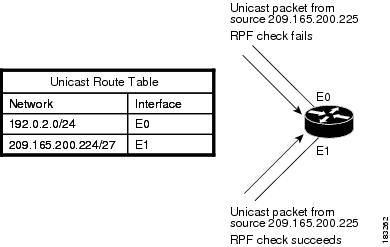
This figure shows an example of RPF checks on packets coming in from different interfaces. The packet that arrives on E0 fails the RPF check because the unicast route table lists the source of the network on interface E1. The packet that arrives on E1 passes the RPF check because the unicast route table lists the source of that network on interface E1.
Cisco NX-OS supports multicasting with Protocol Independent Multicast (PIM) sparse mode. PIM is IP routing protocol independent and can leverage whichever unicast routing protocols are used to populate the unicast routing table. In PIM sparse mode, multicast traffic is sent only to locations of the network that specifically request it. PIM dense mode is not supported by Cisco NX-OS.
Note |
In this publication, the term “PIM” is used for PIM sparse mode version 2. |
To access multicast commands, you must enable the PIM feature. Multicast is enabled only after you enable PIM on an interface of each router in a domain. You can configure PIM for an IPv4 network. By default, IGMP is running on the system.
PIM, which is used between multicast-capable routers, advertises group membership across a routing domain by constructing multicast distribution trees. PIM builds shared distribution trees, on which packets from multiple sources are forwarded, as well as source distribution trees, on which packets from a single source are forwarded.
The distribution trees change automatically to reflect the topology changes due to link or router failures. PIM dynamically tracks both multicast-capable sources and receivers, although the source state is not created in Bidir mode.
The router uses the unicast routing table and RPF routes for multicast to create multicast routing information. In Bidir mode, additional multicast routing information is created.
Note |
In this publication, “PIM for IPv4” refers to the Cisco NX-OS implementation of PIM sparse mode. |
This figure shows two PIM domains in an IPv4 network.
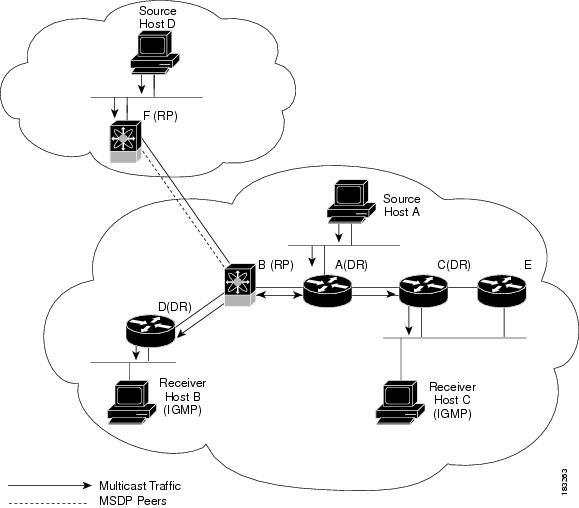
The lines with arrows show the path of the multicast data through the network. The multicast data originates from the sources at hosts A and D.
The dashed line connects routers B and F, which are Multicast Source Discovery Protocol (MSDP) peers. MSDP supports the discovery of multicast sources in other PIM domains.
Hosts B and C receive multicast data by using Internet Group Management Protocol (IGMP) to advertise requests to join a multicast group.
Routers A, C, and D are designated routers (DRs). When more than one router is connected to a LAN segment, such as C and E, the PIM software chooses one router to be the DR so that only one router is responsible for putting multicast data on the segment.
Router B is the rendezvous point (RP) for one PIM domain, and router F is the RP for the other PIM domain. The RP provides a common point for connecting sources and receivers within a PIM domain.
PIM supports these multicast modes for connecting sources and receivers:
Any source multicast (ASM)
Source-Specific Multicast (SSM)
Bidirectional shared trees (Bidir)
Cisco NX-OS supports a combination of these modes for different ranges of multicast groups. You can also define RPF routes for multicast.
Any Source Multicast (ASM) is a PIM tree building mode that uses shared trees to discover new sources and receivers as well as source trees to form shortest paths from receivers to sources. The shared tree uses a network node as the root, called the rendezvous point (RP). The source tree is rooted at first-hop routers, directly attached to each source that is an active sender. The ASM mode requires an RP for a group range. An RP can be configured statically or learned dynamically by the Auto-RP or BSR group-to-RP discovery protocols. If an RP is learned and is not known to be a Bidir-RP, the group operates in ASM mode.
The ASM mode is the default mode when you configure RPs.
Bidirectional shared trees (Bidir) is a PIM mode that, like the ASM mode, builds a shared tree between receivers and the RP but does not support switching over to a source tree when a new receiver is added to a group. In the Bidir mode, the router that is connected to a receiver is called the designated forwarder (DF) because multicast data can be forwarded directly from the designated router (DR) to the receiver without first going to the RP. The Bidir mode requires that you configure an RP.
The Bidir mode can reduce the amount of resources required on a router when there are many multicast sources and can continue to operate whether or not the RP is operational or connected.
Source-Specific Multicast (SSM) is a PIM mode that builds a source tree that originates at the designated router on the LAN segment that receives a request to join a multicast source. Source trees are built by sending PIM join messages in the direction of the source. The SSM mode does not require any RP configuration.
The SSM mode allows receivers to connect to sources outside the PIM domain.
You can configure static multicast RPF routes to override what the unicast routing table uses. This feature is used when the multicast topology is different than the unicast topology.
By default, the Internet Group Management Protocol (IGMP) for PIM is running on the system.
IGMP is used by hosts that want to receive multicast data to request membership in multicast groups. Once the group membership is established, multicast data for the group is directed to the LAN segment of the requesting host.
You can configure IGMPv2 or IGMPv3 on an interface. You have to configure IGMPv3 with (S, G) to support SSM mode. By default, the software enables IGMPv2.
IGMP snooping is a feature that limits multicast traffic on VLANs to the subset of ports that have known receivers. By examining (snooping) IGMP membership report messages from interested hosts, multicast traffic is sent only to VLAN ports that interested hosts reside on. By default, IGMP snooping is running on the system.
Cisco NX-OS provides several methods that allow multicast traffic to flow between PIM domains.
The PIM software uses SSM to construct a shortest path tree from the designated router for the receiver to a known source IP address, which may be in another PIM domain. The ASM and Bidir modes mode cannot access sources from another PIM domain without the use of another protocol.
Once you enable PIM in your networks, you can use SSM to reach any multicast source that has an IP address known to the designated router for the receiver.
Multicast Source Discovery Protocol (MSDP) is a multicast routing protocol that is used with PIM to support the discovery of multicast sources in different PIM domains.
Note |
Cisco NX-OS supports the PIM Anycast-RP, which does not require MSDP configuration. |
Multiprotocol BGP (MBGP) defines extensions to BGP4 that enable routers to carry multicast routing information. PIM and PIM6 can use this multicast information to reach sources in external BGP autonomous systems.
The Cisco NX-OS IPv4 Multicast Routing Information Base (MRIB) is a repository for route information that is generated by multicast protocols such as PIM and IGMP. The MRIB does not affect the route information itself. The MRIB maintains independent route information for each virtual routing and forwarding (VRF) instance in a virtual device context (VDC).
Similar to the MRIB for IPv4 routing information, the M6RIB maintains IPv6 routing information that is generated by protocols such as PIM6 and MLD.
Beginning with Cisco NX-OS Release 10.2(1), Global Boundary Multicast configuration is supported.
You need to configure the {ip | ipv6} multicast group-range prefix-list <prefix-list-name> command in VRF configuration mode to define a global range of IP multicast groups and channels to be permitted or denied for the global multicast boundary. This command is used to disable multicast protocol actions and traffic forwarding for unauthorized groups or channels for all interfaces on a router. The prefix-list configures the boundary. A sample configuration is provided below:
vrf context enterprise
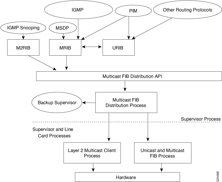
ip multicast group-range prefix-list testThe major components of the Cisco NX-OS multicast software architecture are as follows:
The Multicast FIB (MFIB and M6FIB) Distribution (MFDM) API defines an interface between the multicast Layer 2 and Layer 3 control plane modules, including the MRIB and M6FIB, and the platform forwarding plane. The control plane modules send the Layer 3 route update using the MFDM API.
When the Real-time/flex statistics is enabled with the configuration of hardware profile multicast flex-stats-enable command, the MFDM process sends the real-time packet statistics to MRIB.
Note |
The Bytes value is always lower in MRIB output compared to MFDM output although the packets value is roughly the same, as MFDM strips the outer header and sends only the IP datagram to MRIB. |
The multicast FIB distribution process distributes the multicast update messages to all the relevant modules and the standby supervisor. It runs only on the supervisor.
The Layer 2 multicast client process sets up the Layer 2 multicast hardware forwarding path. It runs on both the supervisor and the modules.
The unicast and multicast FIB process manages the Layer 3 hardware forwarding path. It runs on both the supervisor and the modules.
The following figure shows the Cisco NX-OS multicast software architecture.
A virtual port channel (vPC) allows a single device to use a port channel across two upstream switches. When you configure a vPC, the following multicast features might be affected:
PIM—Cisco NX-OS software for the Cisco Nexus 9000 Series switches does not support PIM Bidir on a vPC.
IGMP snooping—You should configure the vPC peers identically.
It is recommended to configure a snooping querier on a L2 device with lower IP address to force the L2 device as the querier. This will be useful in handling the scenario where multi chassis EtherChannel trunk (MCT) is down.
Beginning with Cisco NX-OS Release 10.2(1q)F, Layer 2 and Layer 3 multicast are supported on Cisco Nexus N9K-C9332D-GX2B platform switches.
Beginning with Cisco NX-OS Release 10.1(2), Layer3 Multicast is supported on N9K-X9624-R2 line card.
Layer 3 Ethernet port-channel subinterfaces are not supported with multicast routing.
Layer 3 IPv6 multicast routing is not supported.
Layer 2 IPv6 multicast packets will be flooded on the incoming VLAN.
Traffic storm control is not supported for unknown multicast traffic.
Layer 3 multicast routing on FEX ports and Layer 3 multicast routing on FEX port channels is supported on Cisco Nexus 9300-FX and -EX platform switches.
Bidirectional mode is not supported on Cisco Nexus 9500 platform switches with -R line cards.
IPv6 multicast is not supported on Cisco Nexus 9500 R Series line cards.
Beginning with Cisco NX-OS Release 10.3(1)F, Multicast consistency checker is supported on Cisco Nexus 9808 platform switches.
Beginning with Cisco NX-OS Release 10.4(1)F, Multicast consistency checker is supported on Cisco Nexus X98900CD-A and X9836DM-A line cards with Cisco Nexus 9808 switches.
Beginning with Cisco NX-OS Release 10.4(1)F, Multicast consistency checker is supported on Cisco Nexus 9804 platform switches, and Cisco Nexus X98900CD-A and X9836DM-A line cards.
Beginning with Cisco NX-OS Release 10.4(1)F, Multicast L3 for IPv4 is supported on Cisco Nexus 9804 platform switches, and Cisco Nexus X98900CD-A and X9836DM-A line cards. However, IPv6 Multicast and Bidirectional modes are not supported.
Beginning with Cisco NX-OS Release 10.3(1)F, the following features are supported on Cisco Nexus 9808 and 9804 platform switches.
Sub interface support IPv4
FPV for IPv4 Multicast
IPv4 L3 multicast
For IPv6 multicast traffic, ensure the MTU size is configured to 40 bytes greater than the allowed MTU so that the complete packets pass through. However, this configuration impacts the IPv4 multicast traffic to allow up to MTU+40 packets also to pass through.
Beginning with Cisco NX-OS Release 10.4(1)F, Multicast is supported on Cisco Nexus 9332D-H2R platform switches. However, FEX is not supported.
After applying global Boundary Multicast configuration within a TRM VXLAN EVPN fabric, use the clear ip mroute filtered groups vrf relevant vrf command to clear the mroutes that are needed to be filtered.
The Global Boundary Multicast configuration commands need to be applied on Multisite Border Gateway switches as well.
Beginning with Cisco NX-OS Release 10.4(2)F, Multicast is supported on Cisco Nexus 93400LD-H1 platform switches. However, FEX is not supported.
Beginning with Cisco NX-OS Release 10.4(3)F, Multicast is supported on Cisco Nexus N9K-C9364CH1 platform switches. However, FEX is not supported.
Beginning with Cisco NX-OS Release 10.6(1)F, following multicast features are supported on Cisco Nexus N9336C-SE1 switches:
IPv4 Layer 2 and Layer 3 multicast
Multicast consistency checker
Layer 3 Physical Interface, port channel, sub-interface, and SVI
Layer 2 port channel
Beginning with Cisco NX-OS Release 10.6(2)F, multicast features are supported on Layer 3 port channel of Cisco Nexus 9800 Series switches.
Beginning with Cisco NX-OS Release 10.6(2)F, support is added for network load balancing (NLB) feature on Cisco Nexus N9336C-SE1, N9396T12C-SE1, and N9348Y12C-SE1 switches.
Beginning with Cisco NX-OS Release 10.6(2)F, support is not added for these feature on Cisco Nexus N9336C-SE1, N9396T12C-SE1, N9348Y12C-SE1, N9324C-SE1U, and N9348Y2C6D-SE1U switches:
PIM Bidir Support
L2 mcast
Multicast over GRE
Multicast Ingress/Egress NAT
MVPN
FPV for IPv6 multicast
MU/UM NAT
FEX
ND ISSU
Beginning with Cisco NX-OS Release 10.6(2)F, support is added for IPv4 and IPv6 multicast on Layer 3-Po interfaces on Cisco Nexus 9808 and 9804 switches.
Remove this configuration before downgrading to earlier releases.
Beginning with Cisco NX-OS Release 10.6(2)F, support is not added for these feature on Cisco Nexus 9808 and 9804 switches:
L2 and SVI multicast
L2-Po interface
PIM Bidir Support
L2 mcast
Multicast over GRE
IPv6 Multicast
Multicast Ingress/Egress NAT
MVPN
MU/UM NAT
FPV for IPv6 Multicast
VPC
Flex stats
NLB
Beginning with Cisco NX-OS Release 10.6(2)F, these multicast features are supported on Cisco N9324C-SE1U and N9348Y2C6D-SE1U switches.
IPv4 Layer 2 and Layer 3 multicast
Multicast consistency checker
Layer 3 Physical Interface, port channel, sub-interface, vPC, and SVI
Layer 2 port channel
Multicast route-aliveness
Hitbit, route statistics (pkts, bytes)
Network load balancing (NLB)
After a multicast routing protocol is restarted, its state is recovered from the MRIB process. When a supervisor switchover occurs, the MRIB recovers its state from the hardware, and the multicast protocols recover their state from periodic message activity. For more information about high availability, see the Cisco Nexus 9000 Series NX-OS High Availability and Redundancy Guide.
Cisco NX-OS can segment operating system and hardware resources into virtual device contexts (VDCs) that emulate virtual devices. The Cisco Nexus 9000 Series switches currently do not support multiple VDCs. All switch resources are managed in the default VDC.
Symptom
This section provides symptoms, possible causes, and recommended actions for when *, G, or S,G entries that are seen in the MRIB with active flow, but are not programmed in MFIB.
Possible Cause
The issue can be seen when numerous active flows are received beyond the hardware capacity. This causes some of the entries not to be programmed in hardware while there is no free hardware index.
If the number of active flows are significantly reduced to free up the hardware resource, inconsistency may be seen between MRIB and MFIB for flows that were previously affected when the hardware table was full until the entry, times out, repopulates, and triggers programming.
There is currently no mechanism to walk the MRIB table and reprogram missing entries in HW after hardware resource is freed.
Corrective Action
To ensure reprogramming of the entries, use the clear ip mroute * command.
 Feedback