
New and Changed Information
The following table provides an overview of the significant changes up to this current release. The table does not provide an exhaustive list of all changes or of the new features up to this release.
| Release Version | Feature | Description |
|---|---|---|
|
There were no major changes from the previous release. |
||
Overview of VXLAN EVPN to SR-MPLS and MPLS LDP Interconnection
Nexus Dashboard Fabric Controller (NDFC) supports the following handoff features:
-
VXLAN to SR-MPLS
-
VXLAN to MPLS LDP
These features are provided on the border devices, that is, border leaf, border spine, and border super spine in the VXLAN fabric using the Data Center VXLAN EVPN template. Note that the devices should be running Cisco NX-OS Release 9.3(1) or later. These DCI handoff approaches are the one box DCI solution where no extra Provider Edge (PE) device is needed in the external fabric.

If the switch is running a Cisco NX-OS Release 7.0(3)I7(X), enabling the MPLS handoff feature causes the switch to remove the NVE related config-profile CLIs when the switch is reloaded.
In the NDFC DCI MPLS handoff feature, the underlay routing protocol to connect a border device to an external fabric is ISIS or OSPF, and the overlay protocol is eBGP. The N-S traffic between the VXLAN fabric and external fabric running SR-MPLS or MPLS LDP is supported. Though, you can use NDFC for connecting two Data Center VXLAN fabrics via SR-MPLS or MPLS LDP.
Supported Platforms and Configurations
The following table provides information about the supported platforms:
|
Feature |
Supported Platforms |
|
VXLAN to SR-MPLS |
Cisco Nexus 9300-FX2/FX3/GX, N9K-X96136YC-R, and Cisco Nexus 3600 R-Series switches |
|
VXLAN to MPLS LDP |
N9K-X96136YC-R and Cisco Nexus 3600 R-series switches |
The following features aren’t supported as they aren’t supported on a switch:
-
Coexisting of MPLS LDP and SR-MPLS interconnections
-
vPC
The VXLAN to SR-MPLS handoff feature comprises the following configurations:
-
Base SR-MPLS feature configuration.
-
Underlay configuration between the DCI handoff device and the device in the external fabric for the underlay connectivity. NDFC supports ISIS or OSPF as the routing protocol for the underlay connectivity.
-
Overlay configuration between a DCI handoff device and a core or edge router in the external fabric, or another border device in another fabric. The connectivity is established through eBGP.
-
VRF profile
The VXLAN to MPLS LDP handoff feature comprises the following configurations:
-
Base MPLS LDP feature configuration.
-
Underlay configuration between the DCI handoff device and the device in the external fabric for the underlay connectivity. NDFC supports ISIS or OSPF as the routing protocol for the underlay connectivity.
-
Overlay configuration between a DCI handoff device and a core or edge router in the external fabric, or another border device in another fabric. The connectivity is established through eBGP.
-
VRF profile
Inter-Fabric Connections for MPLS Handoff
The following two inter-fabric connection links are introduced:
-
VXLAN_MPLS_UNDERLAY for underlay configuration: This link corresponds to each physical link or Layer 3 port channel between the border and the external device (or a P router in MPLS or SR-MPLS). A border device can have multiple inter-fabric connection links as there could be multiple links connected to one or more external devices.
-
VXLAN_MPLS_OVERLAY for eBGP overlay configuration: This link corresponds to the virtual link between a DCI handoff device and a core or edge router in the external fabric, or another border device in another fabric. This inter-fabric connection link can only be created on border devices which meet the image and platform requirement. A border device can have multiple of this type of IFC link as it could communicate to multiple core or edge routers.
These inter-fabric connections can be manually created by using the NDFC Web UI or REST API. Note that the automatic creation of these inter-fabric connections isn’t supported.
VXLAN MPLS Topology
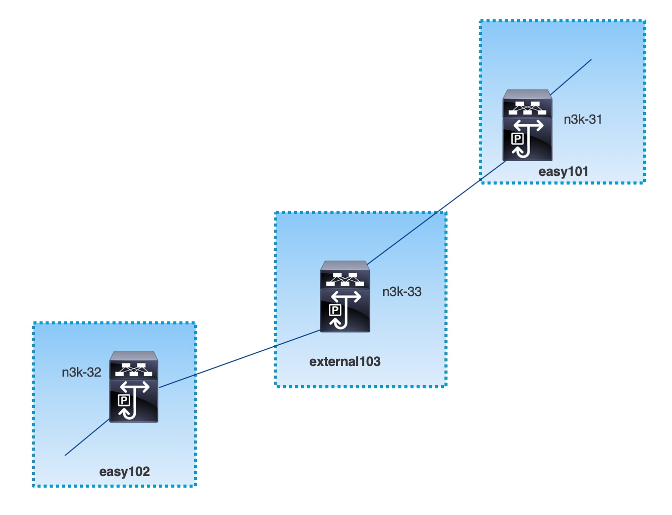
MPLS-SR Topology
MPLS-LDP Topology
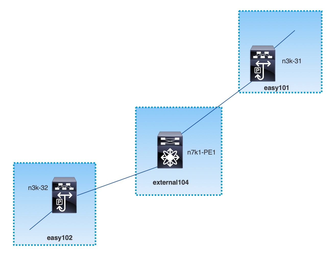
This topology shows only the border devices in the Data Center VXLAN EVPN and the core or edge router in the External Connectivity Network fabric.
-
The fabrics that are using the Data Center VXLAN EVPN template are:
-
easy101
-
easy102
-
-
The fabrics that are using the External Connectivity Network template are:
-
external103
-
external104
-
-
The external fabric external103 is running the MPLS SR protocol.
-
The external fabric external104 is running the MPLS LDP protocol.
-
n3k-31 and n3k-32 are border devices performing VXLAN to MPLS handoff.
-
n7k-PE1 only supports MPLS LDP.
-
n3k-33 supports SR-MPLS.
Configuration Tasks for VXLAN MPLS Handoff
The following tasks are involved in configuring the MPLS handoff features:
-
Editing the fabric settings to enable MPLS handoff.
-
Creating an underlay inter-fabric connection link between the fabrics.
Specify whether you’re using MPLS SR or LDP in the inter-fabric connection link settings.
-
Creating an overlay inter-fabric connection link between the fabrics.
-
Deploying a VRF for VXLAN to MPLS interconnection.
Editing Fabric Settings for MPLS Handoff
This section shows how to edit the fabric settings for the easy fabric and the external fabric to enable the MPLS handoff feature.
Editing Easy Fabric Settings
-
Choose Manage > Fabrics. Choose a appropriate fabric.
-
From Actions drop-down list, choose Edit Fabric to edit the fabric settings.
-
Click the Advanced tab.
Enable MPLS Handoff: Check the check box to enable the MPLS Handoff feature.
Note: For the brownfield import, choose the Enable MPLS Handoff feature. Most of the IFC configuration will be captured in switch_freeform.
Underlay MPLS Loopback Id: Specify the underlay MPLS loopback ID. The default value is 101.
-
Click the Resources tab.
Underlay MPLS Loopback IP Range: Specify the underlay MPLS loopback IP address range.
For eBGP between Border of Easy A and Easy B, Underlay routing loopback and Underlay MPLS loopback IP range must be a unique range. It should not overlap with IP ranges of the other fabrics, else VPNv4 peering will not come up.
-
Click Save to configure the MPLS feature on each border device in the fabric.
-
From Actions drop-down list, choose Recalculate and Deploy.
For more information about remaining fields, see Creating a New VXLAN BGP EVPN Fabric.
Editing External Fabric Settings
-
Choose Manage > Fabrics. Choose a appropriate fabric.
-
From Actions drop-down list, choose Edit Fabric to edit the fabric settings.
-
Under the General Parameters tab, uncheck the Fabric Monitor Mode check box.
-
Click the Advanced tab.
Enable MPLS Handoff: Check the check box to enable the MPLS Handoff feature.
Underlay MPLS Loopback Id: Specify the underlay MPLS loopback ID. The default value is 101.
-
Click the Resources tab.
Underlay MPLS Loopback IP Range: Specify the underlay MPLS SR or LDP loopback IP address range.
Note that IP range should be unique, that is, it should not overlap with IP ranges of the other fabrics.
-
Click Save to configure the MPLS feature on each edge or core router in the fabric.
-
From Actions drop-down list, choose Recalculate and Deploy.
For more information about remaining fields, see Creating an External Fabric.
Creating an Underlay Inter-Fabric Connection
This procedure shows how to create an underlay inter-fabric connection link.
-
Choose Manage > Fabrics.
-
Choose a VXLAN fabric from which you want to create an underlay inter-fabric connection to MPLS.
-
On the Fabric Overview window, click the Links tab.
-
Check the existing links that are already discovered for the fabric.
In this example, the link from easy101 to external103 is already discovered.
-
Select the existing discovered link and click on Actions > Edit.
If a link isn’t discovered, click on Actions > Create and provide all the details for adding an inter-fabric link.
-
In the Link Management - Edit Link window, provide all the required information.
Link Type: Choose inter-fabric.
Link Sub-Type: Choose VXLAN_MPLS_Underlay from the drop-down list.
Link Template: Choose ext_vxlan_mpls_underlay_setup from the drop-down list.
In the General Parameters tab, provide all the details.
IP Address/Mask: Specify the IP address with mask for the source interface.
Neighbor IP: Specify the IP address of destination interface.
MPLS Fabric: Specify whether the external fabric is running SR or LDP.
MPLS SR and LDP can’t coexist on a single device.
Source SR Index: Specify a unique SID index for the source border. This field is disabled if you choose LDP in the MPLS Fabric field.
Destination SR Index: Specify a unique SID index for the destination border. This field is disabled if you choose LDP for the MPLS Fabric field.
SR Global Block Range: Specify the SR global block range. You need to have the same global block range across the fabrics. The default range is from 16000 to 23999. This field is disabled if you choose LDP for the MPLS Fabric field.
DCI Routing Protocol: Specify the routing protocol used on the DCI MPLS underlay link. You can choose either is-is or ospf.
OSPF Area ID: Specify the OSPF area ID if you choose OSPF as the routing protocol.
DCI Routing Tag: Specify the DCI routing tag used for the DCI routing protocol.
-
Click Save.
-
On the Fabric Overview window, click on Actions > Recalculate & Deploy.
-
In the Deploy Configuration window, click Deploy Config.
-
Navigate to the destination fabric from the LAN Fabrics window and perform a Recalculate & Deploy, that is, perform steps 9 and 10.
Creating an Overlay Inter-Fabric Connection
This procedure shows how to create an overlay inter-fabric connection after the underlay inter-fabric connection is created. The overlay inter-fabric connection is the same for MPLS SR and LDP because the overlay connection uses eBGP.
-
On the Links tab, click on Actions > Create.
-
In the Link Management - Create Link window, provide all the details.
Link Type: Choose Inter-Fabric.
Link-Sub Type: Choose VXLAN_MPLS_OVERLAY from the drop-down list.
Link Template: Choose ext_vxlan_mpls_overlay_setup from the drop-down list.
Source Fabric: This field is prepopulated with the source fabric name.
Destination Fabric: Choose the destination fabric from this drop-down box.
Source Device and Source Interface: Choose the source device and the MPLS loopback interface. The IP address of the loopback interface will be used for overlay eBGP peering.
Destination Device and Destination Interface: Choose the destination device and a loopback interface that connects to the source device.
In the General Parameters tab, provide all the details.
BGP Local ASN: In this field, the AS number of the source device is autopopulated.
BGP Neighbor IP: Fill up this field with the IP address of the loopback interface at the destination device for eBGP peering.
BGP Neighbor ASN: In this field, the AS number of the destination device is autopopulated.
-
Click Save.
-
On the Fabric Overview window, click on Actions > Recalculate & Deploy.
-
In the Deploy Configuration window, click Deploy Config.
-
Navigate to the destination fabric from the LAN Fabrics window and perform a Recalculate & Deploy, that is, perform steps 4 and 5.
If there is only one MPLS overlay IFC link on the switch, you can remove it only when there’s no VRF attached to either end of the MPLS overlay link.
Deploying VRFs
This procedure shows how to deploy VRFs for VXLAN to MPLS interconnection.
When you use the 4 byte ASN and auto route target is configured, the route target that is automatically generated is 23456:VNI. If two different VRFs in two different fabrics have the same VNI value, the route-target of the two VRFs would be the same due to auto route target and the value 23456 is always constant. For two fabrics connected via VXLAN MPLS handoff, this could result in unintended route exchange. Therefore, for security reasons, if you want to disable auto route target, you can disable it by customizing the network template and network extension template.
-
Choose Manage > Fabrics. Double-click on a fabric to open Fabric Overview > VRFs.
-
In the VRFs tab, click on Actions > Create to create a VRF. For more information, see the section "VRFs" in About Fabric Overview for LAN Operational Mode Setups.
-
Select the newly added VRF and click Continue.
-
In the VRF Deployment window, you can see the topology of the fabric. Select a border device to attach a VRF to the border device where the MPLS LDP IFC link is created.
In this example, n3k-31 is the border device in the easy101 fabric.
-
In the VRF Extension Attachment window, select the VRF and click the Freeform config button under the CLI Freeform column.
-
Add the following freeform config manually to the VRF:
vrf context _$$VRF_NAME$$_
  address-family ipv4 unicast
    route-target import _$$REMOTE_PE_RT$$_
  address-family ipv6 unicast
    route-target import _$$REMOTE_PE_RT$$_
In the freeform config, REMOTE_PE_RT refers to the neighbor’s BGP ASN and VNI number in the ASN:VNI format if the neighbor is a border device in Easy Fabric managed by NDFC.
-
Click Save Config.
-
(Optional) Enter the Loopback Id and Loopback IPv4 Address and IPv6 address for the border device.
-
Click Save.
-
(Optional) Click the Preview icon in the VRF Deployment window to preview the configuration that will be deployed.
-
Click Deploy.
Perform the same task from Step 3 to Step 11 in the destination fabric if the neighbor is a border device in Easy Fabric managed by NDFC.
Changing the Routing Protocol and MPLS Settings
This procedure shows how to change the routing protocol of a device from using IS-IS to OSPF, or from using MPLS SR to LDP for underlay IFC.
MPLS SR and LDP cannot co-exist on a device, and using both IS-IS and OSPF for MPLS handoff on the same device is not supported.
-
Remove all the MPLS underlay and overlay IFCs from the device that needs the change of DCI routing protocol or MPLS fabric.
-
Click Recalculate & Deploy for each fabric that is involved in the removal of the IFCs.
This step deletes all global MPLS SR/LDP configurations and the MPLS loopback interface that was previously created.
-
Create a new IFC using the preferred DCI routing protocol and MPLS settings. For more information, see Creating an Underlay Inter-Fabric Connection.
Copyright
THE SPECIFICATIONS AND INFORMATION REGARDING THE PRODUCTS IN THIS MANUAL ARE SUBJECT TO CHANGE WITHOUT NOTICE. ALL STATEMENTS, INFORMATION, AND RECOMMENDATIONS IN THIS MANUAL ARE BELIEVED TO BE ACCURATE BUT ARE PRESENTED WITHOUT WARRANTY OF ANY KIND, EXPRESS OR IMPLIED. USERS MUST TAKE FULL RESPONSIBILITY FOR THEIR APPLICATION OF ANY PRODUCTS.
THE SOFTWARE LICENSE AND LIMITED WARRANTY FOR THE ACCOMPANYING PRODUCT ARE SET FORTH IN THE INFORMATION PACKET THAT SHIPPED WITH THE PRODUCT AND ARE INCORPORATED HEREIN BY THIS REFERENCE. IF YOU ARE UNABLE TO LOCATE THE SOFTWARE LICENSE OR LIMITED WARRANTY, CONTACT YOUR CISCO REPRESENTATIVE FOR A COPY.
The Cisco implementation of TCP header compression is an adaptation of a program developed by the University of California, Berkeley (UCB) as part of UCB’s public domain version of the UNIX operating system. All rights reserved. Copyright © 1981, Regents of the University of California.
NOTWITHSTANDING ANY OTHER WARRANTY HEREIN, ALL DOCUMENT FILES AND SOFTWARE OF THESE SUPPLIERS ARE PROVIDED “AS IS" WITH ALL FAULTS. CISCO AND THE ABOVE-NAMED SUPPLIERS DISCLAIM ALL WARRANTIES, EXPRESSED OR IMPLIED, INCLUDING, WITHOUT LIMITATION, THOSE OF MERCHANTABILITY, FITNESS FOR A PARTICULAR PURPOSE AND NONINFRINGEMENT OR ARISING FROM A COURSE OF DEALING, USAGE, OR TRADE PRACTICE.
IN NO EVENT SHALL CISCO OR ITS SUPPLIERS BE LIABLE FOR ANY INDIRECT, SPECIAL, CONSEQUENTIAL, OR INCIDENTAL DAMAGES, INCLUDING, WITHOUT LIMITATION, LOST PROFITS OR LOSS OR DAMAGE TO DATA ARISING OUT OF THE USE OR INABILITY TO USE THIS MANUAL, EVEN IF CISCO OR ITS SUPPLIERS HAVE BEEN ADVISED OF THE POSSIBILITY OF SUCH DAMAGES.
Any Internet Protocol (IP) addresses and phone numbers used in this document are not intended to be actual addresses and phone numbers. Any examples, command display output, network topology diagrams, and other figures included in the document are shown for illustrative purposes only. Any use of actual IP addresses or phone numbers in illustrative content is unintentional and coincidental.
The documentation set for this product strives to use bias-free language. For the purposes of this documentation set, bias-free is defined as language that does not imply discrimination based on age, disability, gender, racial identity, ethnic identity, sexual orientation, socioeconomic status, and intersectionality. Exceptions may be present in the documentation due to language that is hardcoded in the user interfaces of the product software, language used based on RFP documentation, or language that is used by a referenced third-party product.
Cisco and the Cisco logo are trademarks or registered trademarks of Cisco and/or its affiliates in the U.S. and other countries. To view a list of Cisco trademarks, go to this URL: http://www.cisco.com/go/trademarks. Third-party trademarks mentioned are the property of their respective owners. The use of the word partner does not imply a partnership relationship between Cisco and any other company. (1110R)
© 2017-2024 Cisco Systems, Inc. All rights reserved.