
New and Changed Information
The following table provides an overview of the significant changes up to this current release. The table does not provide an exhaustive list of all changes or of the new features up to this release.
|
Release Version |
Feature |
Description |
|
NDFC release 12.2.1 |
ePBR Support |
Beginning with NDFC release 12.2.1, support is available for enhanced policy-based redirect (ePBR), which is used for Layer 4 to Layer 7 service load balancing, and for single-site traffic steering and redirection. |
Layer 4 to Layer 7 Services Configuration
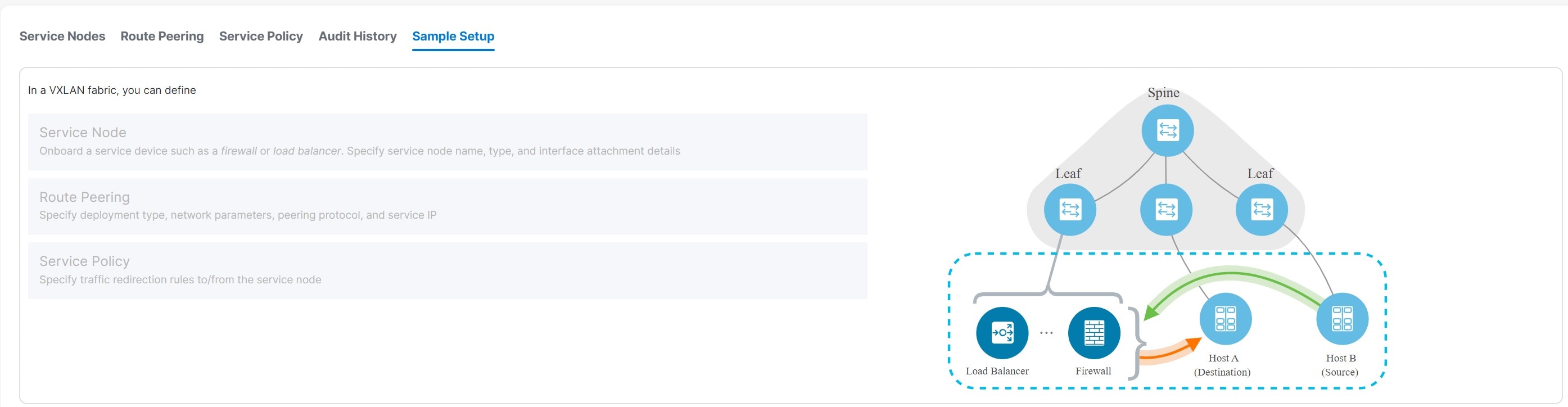
Cisco Nexus Dashboard Fabric Controller introduces the ability to insert Layer 4-Layer 7 (L4-L7) service devices in a data center fabric and to selectively redirect traffic to these L4-L7 service devices. You can add a L4-L7 service appliance, create route peering between the L4-L7 service appliance and the L4-L7 service leaf switch, and then selectively redirect traffic to these L4-L7 service appliances.
Layer 4 to Layer 7 Services
To navigate to the Layer 4 to Layer 7 Services window:
-
Choose Manage > Fabrics.
-
Double-click on the appropriate Data Center VXLAN EVPN fabric to bring up the Fabric Overview window for that fabric.
-
Click the Services tab in that fabric.
You can also bring up the Services information specific to a switch by navigating to:
Manage > Inventory > Switches > Switches Overview > Services
Furthermore, you can watch Service Redirection, a video that demonstrates how to orchestrate a L4-L7 service appliance with a VXLAN Fabric in a data center managed by Cisco Nexus Dashboard Fabric Controller. This demo covers provisioning, defining of service policies, and monitoring of redirected flows.
Service Appliances
You have to create an external fabric and specify that a service appliance resides in that external fabric when creating a service appliance. Nexus Dashboard Fabric Controller does not auto-detect or discover any service appliance. You also have to specify the service appliance name, type, and form factor. The name of the service appliance has to be unique within a fabric. The service appliance is attached to a leaf, border leaf, border spine, border super spine, or a border gateway. Nexus Dashboard Fabric Controller does not define a new switch role for a service switch.
Nexus Dashboard Fabric Controller manages the switches that are attached to a service appliance. Nexus Dashboard Fabric Controller also manages the interfaces of these attached switches. Ensure that the interfaces that the service appliance is attached to are in trunk mode and do not belong to any interface group. The L4-L7 service will not change its mode. In case the attached switches are forming a vPC pair, the name of the attached switch is a combination of both switches.
Double-click a required service name to view the following tabs of the service appliance details window:
MSD Support
This feature supports Multi-Site Domains (MSD). You can choose the MSD member fabric as attached fabric during service appliance creation, create a service appliance (for example, firewall, or load balancer), attach the service appliance to the switch in the selected MSD member fabric, define the route peering and service policies, and deploy relevant configurations on the selected MSD member fabric. For more information on the procedure to configure service, see Configuring Layer 4 to Layer 7 Services.
RBAC Support
The L4-L7 service supports Role-Based Access Control (RBAC) along with fabric access mode.
The admin, stager, and operator, are pre-defined roles in Nexus Dashboard Fabric Controller. The table below lists the various operations that each role can perform.
| Service Operation | Service Appliance | Route Peering | Service Policy |
|---|---|---|---|
|
Create/Update/Delete/Import |
admin |
admin, stager |
admin, stager |
|
List/Export |
admin, stager, operator |
admin, stager, operator |
admin, stager, operator |
|
Attach/Detach |
NA |
admin, stager |
admin, stager |
|
Deploy |
NA |
admin (blocked if fabric is in fabric monitor or read-only mode) |
admin (blocked if fabric is in fabric monitor or read-only mode) |
|
Preview/Deployment History |
NA |
admin, stager, operator |
admin, stager, operator |
PBR Support on WAN Interfaces of Border Switches
Using policy-based redirect (PBR), you can specify an arbitrary network that has not been defined in the top-down configuration as a source or destination network in the service policy. This helps in streamlining policy enforcement for north-south traffic. The Nexus Dashboard Fabric Controller UI lists out routed Layer-3 interfaces of all border switches, standalone or vPC, that have a VRF association. You can then choose the required interface that has to be associated with the defined policy. The border switches include border leaf, border spine, border super spine and border gateway. There can be multiple interface associations. For example, multiple L3 interfaces, subinterfaces, and port-channels can be selected for one border switch. You can also select multiple border switches for interface association. For more information, see the Nexus 9000 Series NX-OS Unicast Routing Configuration Guide.
Depending on the policy direction, the border switch and interface association for 'any' or arbitrary network may not be needed. For example, for a forwarding policy, the border switch and interface input or route-map association is not needed for 'any' or arbitrary destination network. For a reversed policy, the border switch and interface or route-map association is not needed for 'any' or arbitrary source network.
When the policy with 'any' or arbitrary network is attached, the policy related CLIs are generated and associated with the selected L3 routed interfaces of the border switches. The deployment of that policy pushes the CLIs to the selected border switches. The deployment history will include the corresponding entries and can be quickly accessed using VRF filtering. The service policy stats diagram includes the PBR stats of route maps that are associated with the selected L3 routed interfaces of the border switches.
ePBR Support
Beginning with NDFC release 12.2.1, support is available for enhanced policy-based redirect (ePBR), which is used for Layer 4 to Layer 7 service load balancing, and for single-site traffic steering and redirection.
Similar to the PBR feature described in PBR Support on WAN Interfaces of Border Switches, ePBR leverages the policy-based redirect solution to steer traffic and to enable application-based routing. ePBR also allows you to enable service chaining within the same fabric or across fabrics. ePBR services flows are similar to the PBR services flows, as described in the preceding section, consisting of service appliance, route peering, and service policy functions.
The service policy in an ePBR services flow supports service chaining in the same fabric. The service applicance in the service chaining can be any combination of different service node types, and can also have different failure actions defined. You can associate multiple source and destination networks with the service policy, and you can define multiple ACLs, and multiple ACEs in one ACL, for an easier application of the service policy. For more information, see Create Service Policy.
Static Route
The L4-L7 service pushes static routes on all VTEPs, including service leaf switches, where the VRF being referenced in the static route is attached. This expedites service appliance failover with static routes.
Beginning with NDFC release 12.1.3, you can also enable an optional Export Gateway IP flag to export the gateway IP (service appliance IP) address as the next-hop, which will trigger the static routes to be deployed only on the service switches (the switches where the service appliances are attached).
Guidelines and Limitations for L4-L7 Services
-
L4-L7 Service in Nexus Dashboard Fabric Controller does not manage or provision service appliances, such as firewall, load balancer, and Virtual Network Function.
-
The L4-L7 Service feature is supported only on the VXLAN BGP EVPN fabrics with the Data Center VXLAN EVPN template.
-
The service policies defined in this feature leverage policy-based routing (PBR) and, beginning with NDFC release 12.2.1, enhanced policy-based routing (ePBR). See the Nexus 9000 Series NX-OS Unicast Routing Configuration Guide for PBR and ePBR related configurations and constraints.
-
The PBR and ePBR features are exclusive. You cannot enable both PBR and ePBR services flows in the same fabric at the same time.
-
Active/standby, scale-up, and scale-out clustered deployments are supported with the ePBR feature.
-
This feature supports Cisco Nexus 9300-EX and 9300-FX platform switches as leaf, border leaf, border spine, border super spine, and border gateway switches.
-
Configurations involving intra-tenant and inter-tenant firewall for L3 networks, and one-arm Virtual Network Function and one-arm and two-arm load balancer are supported.
-
The existing Nexus Dashboard Fabric Controller topology view is also leveraged to display redirected flows associated with the switches that the service appliance is attached to, and to locate specific redirected flows.
-
L4-L7 Service REST APIs are accessible via Nexus Dashboard Fabric Controller packaged REST API documentation. For more information, see the Cisco Nexus Dashboard Fabric Controller REST API Reference Guide.
-
L4-L7 Services generate Kafka notifications for real-time interaction.
-
Load sharing is not supported.
-
One-arm firewall deployment is supported with eBGP peering and static peering options.
-
IPv6 is supported for L4-L7 Services. See the Cisco Nexus 9000 Series NX-OS VXLAN Configuration Guide for PBR on VXLAN with IPv6 in the Underlay constraints.
-
This feature creates, updates, and deletes the service network, as required. Service networks cannot be created or deleted from the Manage > Fabrics > Networks window.
-
When the NX-API option is enabled on supported fabrics, such as the VXLAN, Enhanced Classic LAN, eBGP, and Campus fabrics, statistics collection can be performed via SSH. You cannot collect any statistics if the NX-API option is disabled.
For more information on NX-API field related information, see the Advanced section in Data Center VXLAN EVPN, Release 12.2.1
Types of Service Devices
The L4-L7 Service in Cisco Nexus Dashboard Fabric Controller supports any vendors service appliance attachments. Typical service appliance types that are deployed in a data center are Firewalls, Load Balancers, and other Layer-4 to Layer-7 products.
Examples of supported Firewall vendors are Cisco Systems, Palo Alto Networks, Fortinet, Check Point Software Technologies, and others.
Examples of supported Load Balancer vendors are F5 Networks, Citrix Systems, A10 Networks, and others.
Note that these example lists are meant to serve as examples and not intended to be exhaustive lists. The L4-L7 service attachment is generic and applies to any vendors service appliance.
Overview
On the Overview tab, you can view the Summary, Route Peering, and Service Policy topology of the selected service appliance.
Click the Refresh icon to view the latest details.
Configuring Fabric Settings for Layer 4 to Layer 7 Service
You must configure certain fabric settings to enable Layer 4 to Layer 7 Service functionality.
To configure these settings:
-
Choose Manage > Fabrics, then click Actions > Create Fabric.
The Create Fabric window is displayed.
-
Provide a Fabric Name, then choose the Data Center VXLAN EVPN template.
-
Click the Advanced tab.
-
Locate the Elastic Services Re-direction (ESR) Options field and choose the appropriate configuration.
The ESR field is available beginning with NDFC release 12.1.3. Choose from one of the following options:
-
PBR: Policy-based routing (default setting)
-
ePBR: Enhanced policy-based routing
-
-
In the Enable Policy-Based Routing (PBR)/Enhanced PBR (ePBR) field, check the checkbox to enable routing of packets based on the specified policy.
-
If you chose PBR in the ESR field above, then checking this checkbox enables policy-based routing (PBR).
-
If you chose ePBR in the ESR field above, then checking this checkbox enables enhanced policy-based routing (ePBR), which enables PBR, sla sender, and ePBR features on the switch.
-
-
Click the Resources tab and specify a VLAN range in the Service Network VLAN Range field.
This is a per switch overlay service network VLAN range. The minimum allowed value is 2 and the maximum allowed value is 4094.
-
Specify a value for the Route Map Sequence Number Range field.
The minimum allowed value is 1 and the maximum allowed value is 65534.
-
Click Save to save the updated configuration.
Configuring Layer 4 to Layer 7 Services
To launch the Layer 4 to Layer 7 Services, or the Elastic Service, on the Cisco Nexus Dashboard Fabric Controller Web UI, navigate to Manage > Fabrics > Fabric Overview > Services.
You can also bring up the Services window specific to a switch by navigating to:
Manage > Inventory > Switches > Switches Overview > Services
The following tabs are shown in the Services window:
-
Service Appliances: Shows the L4-L7 service appliances that you have configured in your NDFC.
-
Route Peering: Shows the route peering configurations in your NDFC. See Route Peering for more information.
-
Service Policy: Shows information on the service policies that you have configured in your NDFC. See Service Policy for more information.
-
Audit History: Allows you to view audit history of the switches and networks that are involved in the selected service policy or route peering.
Adding a Service Appliance
To create a service appliance:
-
Navigate to the Service Appliances tab.
-
Navigate to:
Manage > Fabrics
-
Double-click the appropriate Data Center VXLAN EVPN fabric.
The Overview page for that fabric appears.
-
Click the Services tab.
The Service Appliances subtab should be selected by default.
-
-
Click Actions > Add.
The Create New Service Appliance window is displayed.
The Create New Service Appliance window has three guided steps:
Create Service Appliance
The Create Service Appliance window has two sections:
-
Create Service Appliance
-
Switch Attachments of Service Node(s)
Followed by a Link Template drop-down list.
-
Enter the necessary information in the Create Service Appliance section.
The fields in the Create Service Appliance window are as given below. You must complete the fields marked with an asterisk.
Field
Description
Service Appliance Name
Enter a name for the service appliance. The name can have alphanumeric, underscore, or dash characters.
Service Node Type
Select Firewall, Load Balancer, or Virtual Networking Function.
Appliance Type
This field is introduced in NDFC release 12.2.1.
Options are:
-
Cluster
-
HA: Applicable for two service appliances.
-
Standalone: Applicable for one service appliance.
Form Factor
Select Physical or Virtual.
-
-
Click + Add Switch Attachment.
The Add Switch Attachment popup appears.
-
Enter the necessary information in the Add Switch Attachment popup.
Field
Description
Service Node Name
Select from the list of already-configured service nodes, or click + Create Service Node to create a new one.
External Fabric
Specify the external fabric.
Service Node Interface
Specify the service node interface.
Attached Fabric
Select a fabric from the list.
Attached Switch
Select a switch or a switch pair from the list.
Attached Switch Interface
Select the interface from the list. In case the vPC pair is selected from the Attached Leaf Switch list, the vPC channel will be shown in the Attached Switch Interface list. Otherwise, the port-channel and interfaces with trunk mode are shown in the Attached Leaf Switch Interface list.
Link Template
Select the service_link_trunk, service_link_port_channel_trunk, or the service_link_vpc template from the drop-down list based on the specified attached switch interface type. For more information on template fields, see Templates.
-
Click Save after selecting the appropriate link template.
You are returned to the Create Service Appliance window.
-
Click Save in the Create Service Appliance window.
You advance to the Create Route Peering portion of the process. See Create Route Peering for more information.
Create Route Peering
The Create Route Peering window appears as the second step of the Adding a Service Appliance process. You can also go to the Create Route Peering window after you’ve added a service appliance by navigating to:
Manage > Fabrics > Fabric Overview > Services
Click the Route Peering tab, then click Actions > Add. The Create Route Peering window appears. You must complete the fields marked with an asterisk in this window.
-
In the Peering Name field, specify a name for the peering.
The name can have alphanumeric, underscore, or dash characters.
-
In the Service Appliance Name field, verify that the service appliance that you created in Create Service Appliance appears.
-
In the Deployment field, select the type of deployment.
The fields that appear in the Create Route Peering window depend on the type of L4-L7 service appliance that you chose in the Create Service Appliance window. Depending on the type that you chose (Firewall, Load Balancer, or VNF), the types of deployments are one of the following:
-
Firewall:
-
Intra-Tenant Firewall
-
Inter-Tenant Firewall
-
One-Arm Firewall
-
-
Load Balancer:
-
One-Arm Mode
-
Two-Arm Mode
-
-
VNF:
-
One-Arm VNF
-
-
-
Make the appropriate selection in the Peering Option field, if available.
Options are:
-
Static Peering
-
EBGP Dynamic Peering
-
-
Below the Node Peerings table, click +Add Node Peering.
The Add Node Peering window appears.
-
Complete the remaining configurations for the route peering using the table below.
See Example Route Peering Configurations to see how fields are completed, depending on the type of route peering that you want to configure.

Deletion of service network is not allowed in the Manage > Fabrics > Networks window.
Field
Description
Service Node
Select the service node.
Attach/Detach
Use the toggle to attach or detach the node peering.
First Arm/Inside Network
VRF
Specify the VRF.
Service Networks
Specify the name of the service network.
VLAN ID
Specify the VLAN ID. Valid IDs range from 2 to 3967. Click Propose to retrieve a value from the pre-defined L4-L7 service network VLAN range pool.
Network ID
Specify the Network ID. Valid IDs range from 0 - 16777214. The Network ID will be automatically generated if the value is 0 in this field.
Service Network Template
Select the Service_Network_Universal template from the drop-down list. For more information on the template fields, see Templates.
Service Node IP Address
Specify an IPv4 service node IP address.
Service Node IPv6 Address
Specify an IPv6 service node IP address.
Route Name
Select a route from the list, or click +Create Route option to create a new route. See [Route Peering Tempates] for more information.
Route Template
Displays the route template, if applicable.
Probe Name
Select a probe from the list, or click +Create Probe option to create a new probe. See [Probe Tempate] for more information.
Probe Template
Displays the probe template, if applicable.
Second Arm/Outside Network
VRF
Specify the VRF.
Service Networks
Specify the name of the service network.
VLAN ID
Specify the VLAN ID. Valid IDs range from 2 to 3967. Click Propose to retrieve a value from the pre-defined L4-L7 service network VLAN range pool.
Network ID
Specify the Network ID. Valid IDs range from 0 - 16777214. The Network ID will be automatically generated if the value is 0 in this field.
Service Network Template
Select the Service_Network_Universal template from the drop-down list. For more information on the template fields, see Templates.
Service Node IP Address for Reverse Traffic
Specify an IPv4 service node IP address for reverse traffic.
Service Node IPv6 Address for Reverse Traffic
Specify an IPv6 service node IP address for reverse traffic.
Probe Name
This field is introduced in NDFC release 12.2.1.
-
If you are configuring an ePBR services flow, you must configure the necessary information for the probe. Do not configure probe information if you are configuring a PBR services flow.
-
For active/standby configurations, the node peering for active and standby nodes can share the same service neetwork and routes.
Select a probe from the list, or click +Create Probe option to create a new probe.
Remote Switches
+ Add Remote Switch
Click to add a remote switch, if applicable.
Switch Name
Displays the remote switch name, if a remote switch is added.
Peering template
Displays the peering template used, if a remote switch is added.
-
-
Click Save.
You advance to the Create Service Policy portion of the process. See Create Service Policy for more information.
Example Route Peering Configurations
Following are several example route peering configurations that show how fields are completed, depending on the type of route peering that you want to configure.
Example: Inter-Tenant Firewall Deployment
Peering Option - Static Peering, Inside Network Peering Template - service_static_route, Outside Network Peering Template - service_static_route
The fields in the Create Route Peering window for an Inter-Tenant Firewall deployment are as given below.
|
Field |
Description |
|
Peering Name |
Specify a name for the peering. The name can have alphanumeric, underscore, or dash characters. |
|
Deployment |
Select Inter-Tenant Firewall. |
|
Peering Option |
Select Static Peering or eBGP Dynamic Peering. |
|
Inside Network |
|
|
VRF |
Select a VRF from the drop-down list. |
|
Service Network |
Provide a L4-L7 service network name. |
|
VLAN ID |
Specify the VLAN ID. Valid IDs range from 2 to 3967. Click Propose to retrieve a value from the pre-defined L4-L7 service network VLAN range pool. |
|
Network ID |
Specify the Network ID. Valid IDs range from 0 - 16777214. The Network ID will be automatically generated if the value is 0 in this field. |
|
Service Network Template |
Select the Service_Network_Universal template from the drop-down list. For more information on the template fields, see Templates. |
|
Peering Template |
Select service_static_route or service_ebgp_route from the drop-down list. For more information on the template fields, see Templates. |
|
Outside Network |
|
|
VRF |
Select a VRF from the drop-down list. |
|
Service Network |
Provide a L4-L7 service network name. |
|
VLAN ID |
Specify the VLAN ID. Valid IDs range from 2 to 3967. Click Propose to retrieve a value from the predefined L4-L7 service network VLAN range pool. |
|
Network ID |
Specify the Network ID. Valid IDs range from 0 - 16777214. The Network ID will be automatically generated if the value is 0 in this field. |
|
Service Network Template |
Select the Service_Network_Universal template from the drop-down list. For more information on the template fields, see Templates. |
|
Peering Template |
Select service_static_route or service_ebgp_route from the drop-down list. For more information on the template fields, see Templates. |
Example: One-Arm Mode Load Balancer
The fields in the Create Route Peering window for a One-Arm Firewall deployment are as given below.
|
Field |
Description |
|
Peering Name |
Specify a name for the peering. The name can have alphanumeric, underscore, or dash characters. |
|
Deployment |
Select One-Arm Mode. |
|
Peering Option |
Select Static Peering or eBGP Dynamic Peering. |
|
First Arm |
|
|
VRF |
Select a VRF from the drop-down list. |
|
Service Network |
Provide a L4-L7 service network name. |
|
VLAN ID |
Specify the VLAN ID. Valid IDs range from 2 to 3967. Click Propose to retrieve a value from the pre-defined L4-L7 service network VLAN range pool. |
|
Network ID |
Specify the Network ID. Valid IDs range from 0 - 16777214. The Network ID will be automatically generated if the value is 0 in this field. |
|
Service Network Template |
Select the Service_Network_Universal template from the drop-down list. For more information on the template fields, see Templates. |
|
Peering Template |
Select service_static_route or service_ebgp_route from the drop-down list. For more information on the template fields, see Templates. |
|
Service Appliance IP Section |
|
|
Service Appliance IP Address for Reverse Traffic |
Specify an IPv4 service appliance IP address for reverse traffic. |
|
Service Appliance IPv6 Address for Reverse Traffic |
Specify an IPv6 service appliance IP address for reverse traffic. |
Example: Two-Arm Mode Load Balancer
The fields in the Create Route Peering window for a Two-Arm Mode load balancer deployment are as given below.
|
Field |
Description |
|
Peering Name |
Specify a name for the peering. The name can have alphanumeric, underscore, or dash characters. |
|
Deployment |
Select Two-Arm Mode. |
|
Peering Option |
Select Static Peering or eBGP Dynamic Peering. |
|
First Arm |
|
|
VRF |
Select a VRF from the drop-down list. |
|
Service Network |
Provide a L4-L7 service network name. |
|
VLAN ID |
Specify the VLAN ID. Valid IDs range from 2 to 3967. Click Propose to retrieve a value from the pre-defined L4-L7 service network VLAN range pool. |
|
Network ID |
Specify the Network ID. Valid IDs range from 0 - 16777214. The Network ID will be automatically generated if the value is 0 in this field. |
|
Service Network Template |
Select the Service_Network_Universal template from the drop-down list. For more information on the template fields, see Templates. |
|
Peering Template |
Select service_static_route or service_ebgp_route from the drop-down list. For more information on the template fields, see Templates. |
|
Second Arm |
|
|
VRF |
Select a VRF from the drop-down list. |
|
Service Network |
Provide a L4-L7 service network name. |
|
VLAN ID |
Specify the VLAN ID. Valid IDs range from 2 to 3967. Click Propose to retrieve a value from the pre-defined L4-L7 service network VLAN range pool. |
|
Network ID |
Specify the Network ID. Valid IDs range from 0 - 16777214. The Network ID will be automatically generated if the value is 0 in this field. |
|
Service Network Template |
Select the Service_Network_Universal template from the drop-down list. For more information on the template fields, see Templates. |
|
Service Appliance IP Section |
|
|
Service Appliance IP Address for Reverse Traffic |
Specify an IPv4 service appliance IP address for reverse traffic. |
|
Service Appliance IPv6 Address for Reverse Traffic |
Specify an IPv6 service appliance IP address for reverse traffic. |
Example: One-Arm Virtual Network Function
The fields in the Create Route Peering window for a One-Arm Mode Virtual Network Function deployment are as given below.
|
Field |
Description |
|
Peering Name |
Specify a name for the peering. The name can have alphanumeric, underscore, or dash characters. |
|
Deployment |
Select One-Arm Mode. |
|
Peering Option |
Select Static Peering or eBGP Dynamic Peering. |
|
First Arm |
|
|
VRF |
Select a VRF from the drop-down list. |
|
Service Network |
Provide a L4-L7 service network name. |
|
VLAN ID |
Specify the VLAN ID. Valid IDs range from 2 to 3967. Click Propose to retrieve a value from the predefined L4-L7 service network VLAN range pool. |
|
Network ID |
Specify the Network ID. Valid IDs range from 0 - 16777214. The Network ID will be automatically generated if the value is 0 in this field. |
|
Service Network Template |
Select the Service_Network_Universal template from the drop-down list. For more information on the template fields, see Templates. |
|
IPv4 Gateway/Netmask |
Specify the IPv4 gateway and netmask. |
|
Peering Template |
Select service_static_route or service_ebgp_route from the drop-down list. For more information on the template fields, see Templates. |
|
Service Appliance IP Address for Reverse Traffic |
Specify an IPv4 service appliance IP address for reverse traffic. |
|
Service Appliance IPv6 Address for Reverse Traffic |
Specify an IPv6 service appliance IP address for reverse traffic. |
Create Service Policy
The Create Service Policy window appears as the third step of the Adding a Service Appliance process. You can also go to the Create Service Policy window after you’ve added a service appliance by navigating to:
Manage > Fabrics > Fabric Overview > Services
Click the Service Policy tab, then click Actions > Add. The Create Service Policy window appears. You must complete the fields marked with an asterisk in this window.
-
In the Policy Name field, specify a name for the policy.
The name can have alphanumeric, underscore, or dash characters.
-
In the Source Fabric Name field, verify that the fabric that you selected in Create Service Appliance appears.
-
In the Destination Fabric Name field, verify that the fabric that you selected in Create Service Appliance appears.
-
Use the toggle to attach or detach the service policy. When the service policy is attached or enabled, the corresponding policies are applied to the VRF (tenant), source, and destination networks.
-
In the Source VRF Name field, select a source VRF from the drop-down list.
-
In the Destination VRF Name field, select a destination VRF from the drop-down list.
-
Click + Add Networks.
The Add Networks window appears.
-
In the Source Network field, select an IP address from the drop-down list.
-
In the Destination Network field, select a network from the drop-down list. The destination network must be different from the source network above.
-
Click Save.
-
-
Check the box next to Enable ePBR Statistics to enable this feature.
This field is introduced in NDFC release 12.2.1.
-
Check the box next to Enable Reverse Policy to enable this feature.
This field is introduced in NDFC release 12.2.1.
-
Below the Flow redirect entries table, click + Add Flow Redirect.
The Add Flow Redirect window appears.
-
Complete the remaining configurations for the flow redirect using the table below.
Field
Description
Access Control List (ACL) Name
Select an access control list from the drop-down list. The options are icmp, ip, tcp, and udp.
ACL Template
Select the appropriate ACL template. See ACL Template for more information.
ACL Match Action
Select the appropriate ACL match action. Options are:
-
Redirect
-
Drop
-
Exclude
Service Chaining Name
Enter the service chaining name.
+ Add Service Chaining
Click to add service chaining
Add Service Chaining
Appliance Type
Select the appropriate appliance type for service chaining. Options are Firewall, Load Balancer, or Virtual Networking Function.
Service Appliance Selection
Select the appropriate service appliance for service chaining. Available options are based on the service appliances that you configured using the instructions in Create Service Appliance.
Peering Name
Select the appropriate route peering for service chaining. Available options are based on the route peering that you configured using the instructions in Create Route Peering.
Fail Action
Select the appropriate fail action. Options are:
-
Forward
-
Drop
-
Bypass
-
None
Sequence Number
Enter the sequence number.
Advanced
Hashing Method
Select the appropriate hashing method. Options are:
-
src-ip
-
dst-ip
Hashing Bucket
Enter the hashing bucket. Power of 2.
-
-
Click Save.
Templates
ACL Template
The following probe template is available beginning with NDFC release 12.2.1.
service_acl
IP ACL template for L4-L7 services.
|
Field |
Description |
|
Sequence Number |
Enter the sequence number for the ACL. Valid range: 1 - 4294967295. |
|
Protocol |
Specify the protocol to be used for the ACL. Options are:
|
|
Source IP |
Enter a source IP address for the ACL. This entry can be an IPv4 address, and IPv6 address, or any. |
|
Destination IP |
Enter a destination IP address for the ACL. This entry can be an IPv4 address, and IPv6 address, or any. |
|
Source Port |
Enter the source port number (for example, any or 443). The value in this field is ignored if you selected ip or icmp in the Protocol field. |
|
Destination Port |
Enter the destination port number (for example, any or 443). The value in this field is ignored if you selected ip or icmp in the Protocol field. |
Probe Template
The following probe template is available beginning with NDFC release 12.2.1.
service_endpoint
ePBR service endpoint template for L4-L7 services.
|
Field |
Description |
|
General Parameters |
|
|
Enable Probe |
Check the box to enable the probe of the (reversed) next hop address. |
|
Protocol |
Specify the protocol to be used for the probe. Options are:
|
|
Use Auto-Created Loopback per VRF |
Check the box to use automatically-created loopbacks per VRF. This option is only applicable when the Per VRF Per VTEP Loopback Auto-Provisioning option is enabled in the fabric setting. |
|
Source Loopback Interface IP |
Enter an IP address or address with netmask of the newly created loopback interface for the probe. |
|
Source Loopback Interface IPv6 |
Enter an IPv6 address or address with netmask of the newly created loopback interface for the probe. |
|
Port Number |
Enter the port number for the probe. Valid ranges: 1 - 65535 (recommended range:1025-65534). |
|
User Input for HTTP Probe |
Enter a user input text/filename for an HTTP probe (for example: http://192.168.50.254/index.html). Maximum size: 99. |
|
Advanced |
|
|
Threshold |
Enter the threshold value, in seconds. Valid range: 1 - 60. |
|
Frequency |
Enter the frequency value in seconds. Valid range: 1 - 604800. |
|
Delay Down Change Notification |
Enter the delay down change notification value, in seconds. Valid range: 1 - 180. |
|
Delay Up Change Notification |
Enter the delay up change notification value, in seconds. Valid range: 1 - 180. |
|
Timeout |
Enter the timeout value, in seconds. Valid range: 1 - 604800. |
Route Peering Service Network Template
Service_Network_Universal
|
Field |
Description |
|
General Parameters |
|
|
IPv4 Anycast Gateway/Netmask |
Specify the gateway IP address and mask of the service network. |
|
IPv6 Anycast Gateway/Prefix |
Specify the gateway IPv6 address and prefix of the service network. |
|
VLAN Name |
Specify a name for the VLAN. |
|
Interface Description |
Enter a description for the interface |
|
Advanced |
|
|
Routing Tag |
Specify a routing tag. Valid values range from 0 to 4294967295. |
Route Peering Templates
service_static_route
|
Field |
Description |
|
Static Routes |
Enter the static routes in the Static Routes field. You can enter one static route per line. |
|
Export Gateway IP |
Click to export the gateway IP (the service node IP) address as the next-hop address. |
service_ebgp_route
|
Field |
Description |
|
General Parameters |
|
|
Service Node IP Address or Subnet |
Specify the IPv4 address or address with netmask (for example, 1.2.3.4 or 1.2.3.1/24). An IPv4 or IPv6 address is mandatory. |
|
Loopback IP |
Specify the IPv4 address of the loopback on the switch. Loopback IPv4 or IPv6 address is mandatory. |
|
vPC Peer’s Loopback IP |
Specify the IPv4 address of the peer switch’s loopback. The switch with the smaller serial number will take this value. |
|
Export Gateway IP |
Click to export the gateway IP (the service node IP) address as the next-hop address. |
|
Advanced |
|
|
Service Node IPv6 Address or Prefix |
Specify the IPv6 address of the neighbor. |
|
Loopback IPv6 |
Specify the IPv6 address of the loopback on the switch. |
|
vPC Peer’s Loopback IPv6 |
Specify the IPv6 address of the peer switch’s loopback. |
|
Route-Map TAG |
Specify the route-map tag that is associated with the interface IP. |
|
Interface Description |
Enter a description for the interface. |
|
Local ASN |
Specify a local ASN to override the system ASN. |
|
Advertise Host Routes |
Select this option to enable advertisement of /32 and /128 routes to the edge routers. |
|
Enable eBGP Password |
Select this option to enable the eBGP password. Enabling this option automatically enables the following Inherit eBGP Password from Fabric Settings field. |
|
Inherit eBGP Password from Fabric Settings |
Select this option to inherit the eBGP password from the Fabric Settings. Enabling this option automatically disables the following eBGP Password and eBGP Authentication Key Encryption Type fields. |
|
eBGP Password |
Enabled if you did not enable the Inherit eBGP Password from Fabric Settings field above. If enabled, enter the encrypted eBGP Password hex string. |
|
eBGP Authentication Key Encryption Type |
Enabled if you did not enable the Inherit eBGP Password from Fabric Settings field above. If enabled, enter the BGP key encryption type:
|
|
Enable Interface |
Clear this option to disable the interface. By default, the interface is enabled. |
|
vPC |
|
|
Peering via vPC Peer-Link |
Check this box to configure per-VRF peering through the vPC peer-link. Normally, you might enable the vPC advertise-pip option at the fabric level. Use this Peering via vPC Peer-Link option if you don’t want to have the vPC advertise-pip setting for all of the vPC pairs in the fabric. This option is also needed if you have a shared border deployment with Layer 4 to Layer 7 devices. The remaining fields in this tab become available only if you enable the Peering via vPC Peer-Link option. |
|
Source IP Address/Netmask |
Specify the source IP address and netmask. For example, 192.168.10.1/30. |
|
Destination IP Address |
Specify the destination IP address. For example, 192.168.10.2. The switch with the smaller serial number will take this value. |
|
Source IPv6 Address/Prefix |
Specify the source IPv6 address and netmask. For example, 2001:db9::1/120. |
|
Destination IPv6 Address |
Specify the destination IPv6 address. For example, 2001:db9::10. The switch with the smaller serial number will take this value. |
|
VLAN for Peering Between vPC Peers |
Enter a value for the VLAN peering between vPCs (minimum: 2, maximum: 4094). If no value is specified in this field, the VLAN ID will be automatically assigned from the VLAN pool shown in the vPC Peer Link VLAN Range field on the vPC tab of fabric setting screen. |
Service Node Link Templates
service_link_trunk
|
Field |
Description |
|
General Parameters |
|
|
MTU |
Specifies the MTU for the interface. By default, this is set to jumbo. |
|
SPEED |
Specifies the speed of the interface. By default, this is set to Auto. You can change it to different supported speeds as required. |
|
Trunk Allowed Vlans |
Specify 'none',' all', or VLAN ranges. By default, none is specified. |
|
Enable BPDU Guard |
Specify an option from the drop-down list. The available options are true, false, or no. By default, no is specified. |
|
Enable Port Type Fast |
Check this option to enable spanning tree edge port behavior. By default, this is enabled. |
|
Enable Interface |
Clear the check box to disable the interface. By default, the interface is enabled. |
|
Advanced |
|
|
Source Interface Description |
Enter a description for the source interface. |
|
Destination Interface Description |
Enter a description for the destination interface. |
|
Source Interface Freeform Config |
Enter any addition CLI for the source interface. |
|
Destination Interface Freeform Config |
Enter any addition CLI for the destination interface. |
service_link_port_channel_trunk
|
Field |
Description |
|
Port Channel Mode |
Select a port channel mode from the drop-down list. By default, active is specified. |
|
Enable BPDU Guard |
Specify an option from the drop-down list. The available options are true, false, or no. |
|
MTU |
Specifies the MTU for the interface. By default, this is set to jumbo. |
|
Trunk Allowed Vlans |
Specify 'none',' all', or VLAN ranges. By default, none is specified. |
|
Port Channel Description |
Enter a description for the port channel. |
|
Freeform Config |
Specify the required freeform configuration CLIs. |
|
Enable Port Type Fast |
Check this option to enable spanning tree edge port behavior. By default, this is enabled. |
|
Enable Port Channel |
Check this option to enable the port channel. By default, this is enabled. |
service_link_vpc
This template has no specifiable parameters.
Service Policy Template
service_pbr
|
Field |
Description |
|
General Parameters |
|
|
Protocol |
Select a protocol from the drop-down list. The options are icmp, ip, tcp, and udp. |
|
Source Port |
Specify a source port number. If ip or icmp was selected in the Protocol field above, then the value in this Source Port field is ignored. |
|
Destination Port |
Specify a destination port number. If ip or icmp was selected in the Protocol field above, then the value in this Destination Port field is ignored. |
|
Advanced |
|
|
Route Map Action |
Select an action from the drop-down list. The options are permit or deny. If you select permit, the matched traffic is redirected based on the next-hop option and the defined policy. If you select deny, the traffic is routed based on the routing table rules. |
|
Next Hop Option |
Specify an option for the next-hop. The options are none, drop-on-fail, and drop.If you select none, the matched traffic is redirected based on the defined PBR rules. If you select drop-on-fail, the matched traffic is dropped if the specified next hop is not reachable. If you select drop, the matched traffic is dropped. |
|
ACL Name |
Specify a name for the generated access control list (ACL). If not specified, this is auto-generated. |
|
ACL Name for reversed traffic |
Specify a name for the ACL that is generated for reversed traffic. If not specified, this is auto-generated. |
|
Route map match number |
Specify a route map match number. A valid value ranges from 1 to 65535. If not specified, a route map match sequence number will be retrieved from the predefined resource pool. This number is associated with the name of the ACL. |
|
Route map match number for reversed traffic |
Specify a route map match number for reversed traffic. A valid value ranges from 1 to 65535. If not specified, a route map match sequence number will be retrieved from the predefined resource pool. This number is associated with the name of the ACL that has been generated for reversed traffic. |
You can also customize the templates based on specific requirements.
Route Peering
To navigate to the Route Peering window:
-
Choose Manage > Fabrics.
-
Double-click the appropriate Data Center VXLAN EVPN fabric to bring up the Fabric Overview window for that fabric.
-
Click the Services tab in that fabric.
-
Click the Route Peering tab.
Route peering creates service networks. Nexus Dashboard Fabric Controller supports both static route and eBGP-based dynamic route peering options. After you specify the service network and select the peering policy for the tenant, Nexus Dashboard Fabric Controller automatically creates the service network under the specified tenant. Note that the terms, tenant and VRF, will be used interchangeably in this guide.
You cannot delete the service network. Deletion of service networks is handled automatically during the service route peering deletion process. There can be multiple route peerings defined per tenant/VRF.
To create Route Peering, refer to Create Route Peering.
The following table describes the fields that appear on Route Peering window.
| Field | Description |
|---|---|
|
Service Network One |
|
|
Service Appliance Name |
Specifies the name of the service appliance. |
|
Service Appliance Type |
Specifies the tupe of service appliance:
|
|
Peering Name |
Specifies the peering name of the service. Double-click the Peering Name to view the detailed window. For more information refer to Route Peering Details. |
|
Deployment |
Specifies the type of deployment. The deployment can be one of the following:
|
|
Peering Option |
Specifies the selected peering option. |
|
Remote Peering Enabled |
Specifies whether the remote peering option is enabled or not. |
|
Status |
Specifies the status of service. |
|
Attachment Status |
Specifies the status of service, whether it is attached or detached. |
|
Attached Fabric Name |
Specifies the name of the fabric that the service appliance is attached to. |
|
VRF |
Specifies the name of VRF attached with the service appliance. |
|
Network Name |
Specifies the name of network associated with service appliance. |
|
Gateway IP |
Specifies the gateway IP address of the service appliance. |
|
Service Network Two |
|
|
VRF |
Specifies the name of VRF attached with the service. |
|
Network Name |
Specifies the name of network associated with service appliance. |
|
Gateway IP |
Specifies the gateway IP address. |
|
Service Appliance IP |
Specifies the IP address associated with the service appliance. |
|
Service Appliance IP Address for Reverse Traffic |
Specifies the service appliance IP address for reverse traffic. |
|
Service Appliance IP IPv6 |
Specifies the IPv6 address associated with the service appliance. |
|
Service Appliance IPv6 Address for Reverse Traffic |
Specifies the service appliance IPv6 address for reverse traffic. |
|
Last Updated |
Specifies the last modification time and date for the service appliance. |
The following table describes the action items, in the Actions drop-down list, that appears in the Route Peering window.
| Action Item | Description |
|---|---|
|
Add |
Choose Add. The Create Route Peering window appears. Specify the required parameters and click Save. |
|
Edit |
Choose required peering and click Edit. The Edit Route Peering window appears. Use the toggle to attach or detach the route peering. When the service policy is attached or enabled, the corresponding policies are applied to the VRF (tenant), source, and destination networks. Specify the required parameters and click Save. |
|
Attach |
To attach a specific route peering to a switch, choose the required peering and click Attach.
Bulk attachment, detachment, preview and deployment of route peering are supported and they are limited up to 10 route-peerings only. |
|
Detach |
To detach a specific route peering from a switch, choose the required peering and click Detach. |
|
Preview |
To display the preview, choose the required peering and click Preview. A Preview Route Peering window is displayed. Select a specific switch, network, or VRF from the respective drop-down lists to display the route peerings for specific switches, networks, and VRFs. Click Close to close the window. |
|
Deploy |
To deploy a route peering, choose required peering, click Deploy. A pop-up window appears for confirmation to deploy. Click Deploy. |
|
Import |
To import route peering information as an Excel file, click Import. The Route Peering Import window appears. Click Browse, choose appropriate file, and then click Import to import information about the route peerings. |
|
Export |
To export route peering information as an Excel file, click Export. The Route Peering Export window appears. Click Export to export information about the selected route peering. |
|
Delete |
To delete the route peering, choose appropriate route peering, and click Delete. |
Route Peering Details
To view the route peering details window, navigate to Manage > Fabrics > Fabric Overview > Services > Route Peering and double-click on route peering name. The route peering details window appears, displaying the following tabs:
double-click on the route peering name …. The Overview, Status Details, Service Policy and Deployment History tabs are shown on the route peering detail screen.
-
Overview
-
Status Details
-
Service Policy
-
Deployment History
Overview tab
The Overview tab displays Route Peering Summary with Inside and Outside Network details, Service Policies, and Service Appliance as cards.
Status Details tab
The Status Details tab shows the real-time status of the service network and policy status, along with an updated timestamp and entity.
Service Policy tab
Refer to Service Policy.
Deployment History tab
This tab displays deployment history of the switches and networks that are involved in the route peering. This tab displays information such as the name of the network, VRF, and switch, status, status message, status details, and time of execution.
Remote Peering for VNF Service Devices
Support is available for remote peering for Virtual Network Functions (VNF) Layer 4 to Layer 7 service devices. This allows for the separation of a VNF service appliance’s control plane peering from the physical port attachment.
As part of the process for configuring route peering for a VNF service appliance, you will have the option to specify the eBGP dynamic peering with the remote leaf, border or border gateway switches rather than the default service switch. You will also be able to push remote peering-related configurations through updates to the eBGP template for Layer 4 to Layer 7 services.
The remote peering feature allows VNF to peer with multiple remote leaf, border or border gateway switches through eBGP dynamic peering. As part of the configuration process for remote peering, you can choose either local or remote peering, and whether you want to export the gateway through the eBGP template for remote peering. The configuration status for the remote peering is tracked through the deployment history and policy apply status.
Guidelines and Limitations
-
The remote peering feature is supported only for VNF service devices.
-
The remote peering feature is supported only with eBGP dynamic peering.
-
You can enable either local peering or remote peering with a VNF L4-L7 service device, but you cannot enable both local and remote peering with a VNF L4-L7 service device.
Configuring Remote Peering
To configure remote peering for VNF service devices:
-
Configure the service appliance as you normally would, using the procedures provided in Create Service Appliance.
Specifically for the remote peering feature, when you are in the Create Service Appliance step, select Virtual Networking Function in the Service Appliance Type field.
-
In the Create Route Peering step, configure the route peering as you normally would, with the following settings specifically for this feature.
See Create Route Peering and Route Peering for more information on the standard configuration steps.
Specifically for the remote peering feature, make the following configurations to enable remote peering and to define dynamic peering with multiple remote switches:
-
In the Peering Option field, choose EBGP Dynamic Peering.
-
Click the box next to Enable Remote Peering to enable this feature.
The Enable Remote Peering field appears only if you chose EBGP Dynamic Peering in the Peering Option field.
The Remote Switches field appears after you enable the Enable Remote Peering feature.
-
In the Remote Switches field, click + Add Remote Switch.
The Add Remote Peering window appears.
-
Enter the necessary information to add remote peering.
Field
Description
Remote Switch
Choose the remote switch that will be used with remote peering.
Only the leaf, border, or border gateway switches that are not local to the service appliance are provided as options for this field.
-
If you see a single-switch option in the Remote Switch field (for example, leaf1-v), that means that this is a single, standalone remote switch.
-
If you see a dual-switch option in this field (for example, bgw1-v ~ bgw2-v), that means that this is a vPC pair.
Peering Template
Choose service_ebgp_route as the peering template that you want to use with remote peering.
Complete the configurations using the information provided in [service_ebgp_route]
-
-
Complete any remaining configurations in the Add Remote Peering window, if necessary, then click Save.
-
View the remote peering apply status, which is tracked as part of the route peering policy status.
-
Service Policy
You can define service policies with any or arbitrary network and associate it with an L3 routed interface on border switches. For more information, see PBR Support on WAN Interfaces of Border Switches. The L4-L7 service does not create any VRF or network other than the service networks that are defined during route peering. When you define the service policy between the created networks, the source and destination network can be a subnet, an individual IP address or the networks that are defined in the Services tab of the fabric detail screen.
Choose Manage > Fabrics, then click on Fabric detail view to view the services tab. For intra-tenant firewall, one-arm and two-arm load balancer, the L4-L7 service in Nexus Dashboard Fabric Controller uses Policy-Based Routing (PBR) for service insertion. The inter-tenant firewall does not have a service policy. You only need to create a service appliance and route peering for inter-tenant firewall.
As the source and destination network can be attached or deployed independent of service policy deployment, the tenant/ VRF-related service policy configuration is only attached or pushed to the switch that is attached to the service appliance, and the source and destination network is updated with the service policy-related configuration. You can preview and confirm the generated configuration. By default, the service policy is defined but is not enabled or attached. You have to enable or attach the service policy to activate it.
The service configuration that is related to the source and destination network will be auto-processed when the source and destination networks are to be attached, or auto-updated in case the networks are already attached or deployed. By default, Nexus Dashboard Fabric Controller will collect statistics every 5 minutes and store it in the database for aggregation and analysis. By default, the statistics are stored for a maximum of 7 days.
The service insertion is effective only on the flows to be created. There is no impact on any existing flows. Deletion of a network is not allowed in case an enabled service policy is associated with that network.
The L4-L7 service integration is built on top of the easy fabric policy enforcement. Choose Manage > Fabrics to create a VXLAN EVPN fabric and then import Cisco Nexus 9000 Series switches into the fabric with predefined fabric policies.
To create a service policy, refer to Create Service Policy.
The following table describes the fields that appear in the Service Policy window.
| Field | Description |
|---|---|
|
Policy Name |
Specifies the policy name of service. Double-click on Policy Name, detailed window appears. For more information refer to Service Policy Details. |
|
Route Peering |
Specifies the route peering name. |
|
Status |
Specifies the status of service. |
|
Attachment Status |
Specifies the status of service, whether it is attached or detached. |
|
Source VRF |
Specifies the name of VRF attached with the service appliance. |
|
Source Network |
Specifies the name of source network. |
|
Destination VRF |
Specifies the name of destination VRF attached with the service appliance. |
|
Destination Network |
Specifies the name of destination network. |
|
Service Appliance IP |
Specifies the IP address associated with the service appliance. |
|
Service Appliance IP Address for Reverse Traffic |
Specifies the service appliance IP address for reverse traffic. |
|
Service Appliance IPv6 |
Specifies the IPv6 address associated with the service appliance. |
|
Service Appliance IPv6 Address for Reverse Trafficv6 |
Specifies the service appliance IPv6 address for reverse traffic. |
|
Reverse Enabled |
Specifes if service appliance for reverse traffic is enabled or not. |
|
Route Map Action |
The options are permit or deny. If you select permit, the matched traffic is redirected based on the next hop option and the defined policy. If you select deny, the traffic is routed based on the routing table rules. |
|
Next Hop Option |
Specify an option for the next hop. The options are none, drop-on-fail, and drop. If you select none, the matched traffic is redirected based on the defined PBR rules. If you select drop-on-fail, the matched traffic is dropped if the specified next hop is not reachable. If you select drop, the matched traffic is dropped. |
|
Last Updated |
Displays the time at which the service policy was last updated. |
The following table describes the action items, in the Actions drop-down list, that appears in the Service Policy window.
| Action Item | Description |
|---|---|
|
Add |
Choose Add. The Create Service Policy window appears. Specify the required parameters and click Save. |
|
Edit |
Choose required service policy and click Edit. The Edit Service Policy window appears. Use the toggle to attach or detach the service policy. When the service policy is attached or enabled, the corresponding policies are applied to the VRF (tenant), source, and destination networks. Specify the required parameters and click Save. |
|
Attach |
To attach a specific service policy to a switch, choose the required policy and click Attach.
Bulk attachment, detachment, preview and deployment of route peering are supported and they are limited up to 10 service policies only. |
|
Detach |
To detach a specific service policy from a switch, choose the required service policy and click Detach. |
|
Preview |
To display the preview, choose the required peering and click Preview. A Preview Service Policy window is displayed. Select a specific switch, network, or VRF from the respective drop-down lists to display the service policy for specific switches, networks, and VRFs. Click Close to close the window. |
|
Deploy |
To deploy a service policy, choose required service policy, click Deploy. A pop-up window appears for confirmation to deploy. Click Deploy. |
|
Import |
To import service policy information as an Excel file, click Import. The Service Policy Import window appears. Click Browse, choose appropriate file, and then click Import to import information about the service policy. |
|
Export |
To export route service policy information as an Excel file, click Export. The Service Policy Export window appears. Click Export to export information about the selected service policy. |
|
Delete |
To delete the service policy, choose appropriate service policy, and click Delete. |
Service Policy Details
To view service policy window, navigate to Services, double-click on required service Name, service policy details window appears. You can view below tabs on the window:
-
Overview
-
Status Details
-
Route Peering
-
Service Policy
Overview
The Overview tab displays Policy Summary, Service Appliance, and Route Peering with Inside and Outside Network as cards.
Status Details
This tab displays Resource Type, Fabric Name, Resource Name details associated with the selected service policy
Statistics
This tab displays statistical information about the configured service policies. Select a time range for which the statistics should be displayed from the Time Range drop-down box. You can select the date from the calendar displayed on the window and the time by clicking select time at the bottom right corner of the window. You can also display statistics from the last 15 minutes, 1 hour, 6 hours, 1 day, 1 week, and 1 month. Select the required time range and click Apply. Select a switch for which the statistics should be displayed from the Switch drop-down list. The statistics are then displayed for the selected switch in the specified time range.
Click Clear Stats to reset the statistics for a specific policy on all involved switches. If multiple policies are sharing the same route map, then the statistics of other policies are also impacted.
Viewing Deployment History
This tab displays deployment history of the switches and networks that are involved in the service policy. This tab displays information such as the name of the network, VRF, switch name, status, status message, status details, and time of execution.
Refreshing a Service Appliance
To refresh the list of service appliances that is displayed in the Service Appliances window, click the Refresh icon.
Viewing Audit History
To view audit history of the switches and networks that are involved in the selected service policy or route peering, click the Audit History tab in the Services window.
Audit Logs table in the Audit History window displays information about all the actions that have been performed:
| Field | Description |
|---|---|
|
User Name |
Specifies the user name of service appliance. |
|
User Role |
Specifies the user role name by whom latest action performed. |
|
Action Taken |
Specifies the latest action performed. |
|
Entity |
Specifies the name of service appliance. |
|
Details |
Sepcifies the details of the service appliance. |
|
Status |
Sepcifies the status of the service appliance. |
|
Time |
Sepcifies the action time on that node. |
|
More Info |
Click More Info to view detailed information of selected service appliance. |
-
Creation of service appliances, route peering, and service policies
-
Deletion of service appliances, route peering, and service policies
-
Update of service appliances, route peering, and service policies
-
Attachment and detachment of route peering, and service policies
-
Deployment of route peering and service policies
Audit logs are generated when the actions above are performed, these audit log is saved with the name of the user who has performed the action, the role of the user, the action taken, the entity on which the action was performed, details about the action, the status, and the time at which the action was performed.
To delete older audit reports, click Action > Purge Audit History, specify the maximum retained dates and confirm deletion. Note that only users with the admin role can delete audit log entries.
Importing Service Appliances
To import service appliances from an Excel file:
-
Navigate to the Service Appliances tab:
Manage > Fabrics > Fabric Overview > Services > Service Appliances
-
Click Actions > Import.
The Service Appliance Import window appears.
-
Click Browse or drag and drop the Excel file, then click Import to import information about the service appliances.
You can also restore the service appliance level data by clicking Actions > Import to import data about the service appliances from an Excel file.
Exporting Service Appliances
You can back up data at the service appliance level by clicking Actions > Export option to export data about the service appliances to an excel file. Data regarding all the service appliances, the respective route peerings, and service policy, is exported.
You can also export data for a specific service appliance by selecting the appliance and clicking Actions > Export. A confirmation window appears, click Export.
Editing a Service Appliance
To edit a service appliance from the Cisco Nexus Dashboard Fabric Controller Web UI, perform the following steps:
-
Choose a service appliance from the table and click Actions > Edit.
-
The Edit Service Appliance window is displayed.
Make the required changes and click Save.
Deleting a Service Appliance
To delete a service appliance from the Cisco Nexus Dashboard Fabric Controller Web UI, perform the following steps:
-
Ensure that the service appliance that has to be deleted has no route peering or service policies associated with it.
In case there are service policies or route peering associated with the service appliance, the deletion is blocked with a warning indicating that any route peering or service policies associated with the service appliance have to be removed before deleting the service appliance.
-
Select a service appliance from the table and click Actions > Delete.
Copyright
THE SPECIFICATIONS AND INFORMATION REGARDING THE PRODUCTS IN THIS MANUAL ARE SUBJECT TO CHANGE WITHOUT NOTICE. ALL STATEMENTS, INFORMATION, AND RECOMMENDATIONS IN THIS MANUAL ARE BELIEVED TO BE ACCURATE BUT ARE PRESENTED WITHOUT WARRANTY OF ANY KIND, EXPRESS OR IMPLIED. USERS MUST TAKE FULL RESPONSIBILITY FOR THEIR APPLICATION OF ANY PRODUCTS.
THE SOFTWARE LICENSE AND LIMITED WARRANTY FOR THE ACCOMPANYING PRODUCT ARE SET FORTH IN THE INFORMATION PACKET THAT SHIPPED WITH THE PRODUCT AND ARE INCORPORATED HEREIN BY THIS REFERENCE. IF YOU ARE UNABLE TO LOCATE THE SOFTWARE LICENSE OR LIMITED WARRANTY, CONTACT YOUR CISCO REPRESENTATIVE FOR A COPY.
The Cisco implementation of TCP header compression is an adaptation of a program developed by the University of California, Berkeley (UCB) as part of UCB’s public domain version of the UNIX operating system. All rights reserved. Copyright © 1981, Regents of the University of California.
NOTWITHSTANDING ANY OTHER WARRANTY HEREIN, ALL DOCUMENT FILES AND SOFTWARE OF THESE SUPPLIERS ARE PROVIDED “AS IS" WITH ALL FAULTS. CISCO AND THE ABOVE-NAMED SUPPLIERS DISCLAIM ALL WARRANTIES, EXPRESSED OR IMPLIED, INCLUDING, WITHOUT LIMITATION, THOSE OF MERCHANTABILITY, FITNESS FOR A PARTICULAR PURPOSE AND NONINFRINGEMENT OR ARISING FROM A COURSE OF DEALING, USAGE, OR TRADE PRACTICE.
IN NO EVENT SHALL CISCO OR ITS SUPPLIERS BE LIABLE FOR ANY INDIRECT, SPECIAL, CONSEQUENTIAL, OR INCIDENTAL DAMAGES, INCLUDING, WITHOUT LIMITATION, LOST PROFITS OR LOSS OR DAMAGE TO DATA ARISING OUT OF THE USE OR INABILITY TO USE THIS MANUAL, EVEN IF CISCO OR ITS SUPPLIERS HAVE BEEN ADVISED OF THE POSSIBILITY OF SUCH DAMAGES.
Any Internet Protocol (IP) addresses and phone numbers used in this document are not intended to be actual addresses and phone numbers. Any examples, command display output, network topology diagrams, and other figures included in the document are shown for illustrative purposes only. Any use of actual IP addresses or phone numbers in illustrative content is unintentional and coincidental.
The documentation set for this product strives to use bias-free language. For the purposes of this documentation set, bias-free is defined as language that does not imply discrimination based on age, disability, gender, racial identity, ethnic identity, sexual orientation, socioeconomic status, and intersectionality. Exceptions may be present in the documentation due to language that is hardcoded in the user interfaces of the product software, language used based on RFP documentation, or language that is used by a referenced third-party product.
Cisco and the Cisco logo are trademarks or registered trademarks of Cisco and/or its affiliates in the U.S. and other countries. To view a list of Cisco trademarks, go to this URL: https://www.cisco.com/go/trademarks. Third-party trademarks mentioned are the property of their respective owners. The use of the word partner does not imply a partnership relationship between Cisco and any other company. (1110R)
© 2017-2024 Cisco Systems, Inc. All rights reserved.