
Overview of HF6100-64ED
Overview of the Cisco HF6100-64ED series switch
Cisco 6000 series switches are cloud-managed network fabric switches. These switches are part of the Cisco Nexus Hyperfabric fabric-as-a-service (FaaS) solution, and allows you to design and build a physical network.
The Cisco Nexus Hyperfabric FaaS is an automated and cloud-managed scalable data center fabric solution that simplifies network deployment and operations by offering networking as a managed service. The FaaS solution enables organizations to design, deploy, manage, and scale multiple data center network fabrics with ease.
The HF6100-64ED switch consists of
- 2 rack unit (RU) size
- 64 x 800G OSFP800 ports
- 2 power supply slots, and
- 4 fan trays.
The Cisco HF6100-64ED switch operates on the Cisco Silicon One G200 network processor, and provides 51.2 Tbps of network bandwidth. The Cisco HF6100-64ED switch is a fixed port, high density, two rack unit form-factor switch designed for hyperscale data centers. A hyperscale data center is a very large-scale data center that supports massive computing and data storage needs with extreme scalability and efficiency.
The Cisco HF6100-64ED switch supports 64 x 800G OSFP800 ports. This switch supports Cisco-qualified open-source network operating systems, such as SONiC (Software for Open Networking in the Cloud).
Installation workflow
The illustration describes the installation workflow.

Console speed
The console speed is 115200 baud, 8 data bits, 1 stop bit and no parity.
Front panel
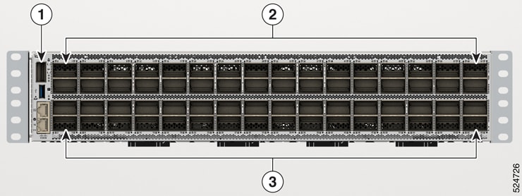
The front panel of the HF6100-64ED switch supports
- 2 X 32 OSFP800 ports
- LEDs
- RJ-45 console port
- RJ-45 Ethernet management port
This illustrations displays the front panel of the HF6100-64ED switch with its components.
|
1 |
32 X OSFP800 ports |
|
2 |
32 X OSFP800 ports |
LEDs
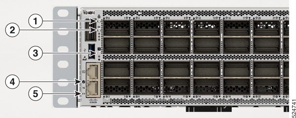
You can use the switch light-emitting diodes (LEDs) to monitor switch activity and its performance.
|
1 |
Beacon LED |
|
2 |
Status LED |
|
3 |
RJ-45 port LED |
|
4 |
Activity LED: displays the activity of the ports |
Beacon LEDs
The unique device identifier (UID) and the beacon LED can be turned on by the administrator to indicate that the switch needs attention. It helps the administrator identify the switch. The beacon can be enabled by pressing the UID button on the switch front panel.
Port LEDs
Each Ethernet module slot has a port LED. These port LEDs, as a group or individually, display information about the switch and about the individual ports. The port mode determines the type of information shown by the port LEDs.
To select or change a mode, press the Mode button until the desired mode is highlighted. When you change port modes, the meanings of the port LED colors also change.
This table describes the port LEDs.
|
Color |
Description |
|---|---|
|
Green |
Port is operationally up. |
|
Off |
No link, or port was administratively shut down. |
RJ-45 Ethernet management port LEDs
This table describes the management port LEDs.
|
Green |
Yellow |
Description |
|---|---|---|
|
Off |
On |
Link up, but no activity |
|
Off |
Blink |
Link up and active |
|
On |
On |
Link up and active |
|
On |
Off |
Link up, but no activity |
|
Blink |
Off |
Link up, but no activity |
|
Off |
Off |
Link down. |
RJ-45 console port LEDs
This table describes the RJ-45 console port LEDs.
|
Green |
Yellow |
Description |
|---|---|---|
|
Off |
On |
Link up, but no activity |
|
Off |
Blink |
Link up and active |
|
On |
On |
Link up and active |
|
On |
Off |
Link up, but no activity |
|
Blink |
Off |
Link up, but no activity |
|
Off |
Off |
Link down. |
Status LEDs
This table explains the status LEDs.
|
Color |
Description |
|---|---|
|
Green |
Switch is active. |
|
Flashing red |
Flashing red can be due to
|
Rear panel
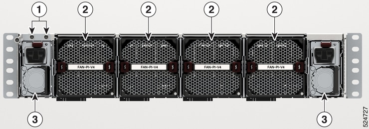
The rear panel of the HF6100-64ED switch supports
- Fan tray with four fans
- Two power supply modules
This illustration shows the rear panel of the HF6100-64ED switch with its components.
|
1 |
Ground lugs |
|
2 |
Fans (1 to 4 from left to right) |
|
3 |
Power supply modules, PSU0 (left) and PSU1 (right) |
Power supply units
An internal power supply module converts external electrical power (either AC or DC) into the precise DC voltages required to operate the switch's internal components.
Cisco HF-6100-64ED has two internal power supply module slots. The PSU1 is on the left side of the rear panel and PSU2 is at the right side of the rear panel.
You can use one or two power supply modules All empty power supply module slots must be filled with a blank module. By default, these switches ship with only one power supply module, and you can purchase more power supply modules when you order the switch or at a later date.
Fan modules
HF6100-64ED has four fan modules at the rear of the switch. The fans are hot-swappable and numbered from left to right.
A powered-on switch should always have more than one operational fan. The switch can operate with three operational fans and one nonfunctional fan, but the failed fan should be replaced as soon as possible to avoid a service interruption due to a second fan fault. A switch with one or more fans failed or removed will operate with fans at a faster speed, producing increased sound.
 Note
NoteThe switch requires three fans for proper cooling.
NoteSharp edges on the fan module can cause serious injury. Keep fingers clear.
Fan LEDs
This table describes the fan LEDs.
|
Color |
Status |
|---|---|
|
Amber |
Fans are inserted into the device and are waiting to become active. |
|
Flashing amber |
The specific fan tray is not working or failed. |
|
Flashing blue |
The operator has activated this LED to identify the specific fan tray. |
|
Green |
Fans are operating. |
|
Off |
Fan tray is not receiving power. |
Ports
This section describes the various ports on Cisco HF6100-64ED
OSPF800 ports
Octal Small Form-factor Pluggable 800 (OSFP800) ports use the OSFP form factor, which is larger than QSFP and QSFP-DD modules, and allows better thermal dissipation and supports 800G Ethernet speeds. Each OSFP800 port can handle 800 Gbps.
OSFP800 ports comply with IEEE 802.3ck and IEEE 802.3cu-2021 standards for 800G Ethernet, using Pulse Amplitude Modulation with 4 levels (PAM4) modulation and Forward Error Correction (FEC) to achieve high data integrity and performance. PAM4 is a high-speed signal modulation technique that encodes two bits of data per symbol by using four distinct amplitude levels in the signal waveform.
OSFP800 ports on Cisco devices support a range of optical modules, including OSFP-800G-DR8 modules that can transmit data up to 500 meters over single-mode fiber.
OSFP800 ports enable seamless connectivity between devices and support next-generation network speeds with efficient power consumption and cooling.
RJ-45 Ethernet management port
The management ports connect the switch to a PC running Microsoft Windows or to a terminal server.
The RJ-45 Ethernet management port is a dedicated network interface, used for out-of-band management of the Cisco device. Ethernet management port connection uses a standard RJ-45 crossover or straight-through cable.
RJ-45 console port
The RJ-45 console port is a serial communication port used for device management and configuration. It allows direct access to the Cisco device’s CLI for initial setup, troubleshooting, or recovery when network access is unavailable. The console port transmits serial data rather than Ethernet traffic.
The RJ-45 console port uses the optional RJ-45-to-DB8 female cable physical connector. The USB console interface speeds are the same as the RJ-45 console interface speeds.
USB ports
USB ports provide access to external USB flash devices (also known as thumb drives or USB keys). These ports support flash drives with capacities from 128 MB to 256 GB.
The USB console port
- Serves as a serial console interface for device management.
- Connects a computer or terminal directly to the Cisco device for configuration purposes.
- Enables terminal communication to configure routers, switches, firewalls, or other Cisco network devices.
You can use the flash drive with standard file system access such as read, write, erase, and copy, and the ability to format the flash device with a File Allocation Table 16 (FAT16) file system. FAT16 file format supports up to 2GB maximum volume.
USB ports enable you to automatically upgrade the internal flash with the USB drive's configuration and image for emergency switch recovery using USB auto-upgrade. This feature checks the internal flash for a bootable image and configuration and if either image or the configuration is not available, then the USB drive is checked for boot images and configuration. If the boot image and configuration are available, these are copied to the flash for a reboot.