
Install the Switch - HF6100-64ED
Unbox or unpack the switch
Box contents
The shipping box contains the model of the switch and other components needed for installation. Some components are optional, depending on your order.
|
1 |
Cisco HF6100-64ED |
8 |
1 Grounding plate (L-bracket) |
|
2 |
Product documentation and compliance document |
9 |
2 M4.0 x 6mm flat-head screws |
|
3 |
2 rack mounting brackets |
10 |
Grounding lug |
|
4 |
19 M3.0 x 6mm Phillips flat-head screws |
11 |
2 M4.0 x 6mm pan-head screws |
|
5 |
2 Rack-mount guide rails |
12 |
(Optional) AV power cord |
|
6 |
12 M4.0 x 6mm Phillips flat-head screws |
13 |
(Optional) RJ-45/DB9 console cable |
|
7 |
2 Rack-mount guide rails |
- |
- |
Spare accessory kits
This table describes the spare accessory kit for HF6100-64ED. The spare accessory kit must be ordered separately based on your requirements.
|
Part number (add = for spare) |
Description |
|---|---|
|
8K-2RU-KIT-SB= |
2RU chassis rail kit |
 Note
Note8K-2RU-KIT-SB is part of the standard accessory kit that ships along with the switch. However, based on your requirements, you can also order it separately.
Use the box contents
Do not discard the shipping container when you unpack the switch. Flatten the shipping cartons and store them with the pallet. You will need these containers if you need to move or ship the switch in the future.
Step 1 | Verify that you have received all the listed equipment:
|
Step 2 | Verify the contents of the accessory kits. |
Tools and equipment
To connect the system ground, you need these tools and materials.
-
Grounding lug: When using the double-hole lug connector provided with the system, the ground wire must be 6 AWG only. Otherwise, a supported closed-loop ring connector must be used for 8-14 AWG wire.
- Two-hole 2 AWG lug is provided with the accessory kit. If you choose to use a different sized ground wire, you must procure your own two-hole lug that has .25 inch holes and .625 inch spacing between the holes.
- Grounding screws: Two M4.0 x 6mm Phillips pan-head screws. Supplied as part of the accessory kit.
- Grounding wire: Not supplied as part of accessory kit. The grounding wire should be sized according to local and national installation requirements. For U.S. installations, AC power supply systems require a 14 AWG copper conductor. Commercially available 8-14 AWG wire is recommended. DC power supply systems with 930W power supply module require a 12 AWG wire and 1500W power supply module require a 8 AWG wire. The length of the grounding wire depends on the proximity of the switch to proper grounding facilities.
- Crimping tool to crimp the grounding wire to the grounding lug.
- Wire-stripping tool to remove the insulation from the grounding wire.
- 2 M4 screws to fix a ground lug.
To rack mount the switch, you need these tools
- 16 M4 screws to fix brackets
- 3/16-inch flat-blade screwdriver.
- Antistatic mat or antistatic foam.
- ESD wrist strap or other grounding device.
- No. 1 and number 2 Phillips screwdrivers with torque capability to rack-mount the chassis.
- Tape measure and level.
Ground the switch
Adhere to these safety warnings before grounding the switch.
Installations that rely solely on system grounding using only an AC third-prong ground run a substantially greater risk of equipment problems and data corruption than those installations that use both the AC third-prong ground and a properly installed system ground.
The system ground provides additional grounding for EMI shielding requirements and grounding for the low voltage supplies (DC-DC converters) on the modules. You must observe the following system grounding guidelines for your chassis:
- You must install the system ground connection with any other rack or system power ground connections that you make. The system ground connection is required if modules are installed or if this equipment is installed in a U.S. or European Central Office.
- You must connect both the system ground connection and the power supply ground connection to an earth ground. The system ground connection is required if Foreign Exchange Station (FXS) modules are installed or if this equipment is installed in a U.S. or European Central Office.
- When using DC-input power supplies, you must install the system ground before you attach the source DC power cables to the DC Power Entry Module (PEM). Power down the chassis before attaching the system ground.
NoteIn all situations, grounding practices must comply with Section 250 of the National Electric Code (NEC) requirements or local laws and regulations. A 6 American Wire Gauge (AWG) grounding wire is recommended from the chassis to the rack ground or directly to the common bonding network (CBN). The equipment rack should also be connected to the CBN with a 6 AWG grounding wire.
The system ground serves as the primary safety ground for chassis that are equipped with DC-input power supplies. The DC-input power supplies for these chassis do not have a separate ground.
 Warning
Statement 1024—Ground Conductor
This equipment must be grounded. To reduce the risk of electric shock, never defeat the ground conductor or operate the equipment in the absence of a suitably installed ground conductor. Contact the appropriate electrical inspection authority or an electrician if you are uncertain that suitable grounding is available.
WarningStatement 1046—Installing or Replacing the Unit
To reduce risk of electric shock, when installing or replacing the unit, the ground connection must always be made first and disconnected last.
If your unit has modules, secure them with the provided screws.
WarningStatement 1101—Connected To Grounded Outlet
In the Scandinavian countries (Denmark, Finland, Iceland, Norway, and Sweden) the appliance must be connected to a grounded outlet.
NoteStatement 1101 is applicable to AC units only.
NoteGrounding the chassis is required, even if the rack is already grounded. A grounding pad with two threaded holes is provided on the chassis for attaching either a grounding lug or a grounding plate used to attach the ground lug to the chassis. The ground lug must be Nationally Recognized Testing Laboratory (NRTL)-listed. In addition, a copper conductor (wires) must be used and the copper conductor must comply with NEC for ampacity.
NoteWhen terminating the frame ground, do not use soldering lug connectors, screwless (push-in) connectors, quick connect connectors, or other friction-fit connectors.
Connect the switch to the ground
To establish an earth ground for the chassis, you must attach a grounding cable from the chassis’ grounding lug to the rack.
Step 1 | Use a wire-stripping tool to remove approximately 0.75 inches (19 mm) of the covering from the end of the 6 AWG grounding cable. | ||||||||
Step 2 | Insert the stripped end of the grounding cable into the open end of the grounding lug. | ||||||||
Step 3 | Use the crimping tool to secure the grounding cable (6 AWG cable) in the grounding lug. | ||||||||
Step 4 | Attach the grounding cable: Position the grounding lug against the grounding plate or the grounding point on the chassis to ensure solid metal-to-metal contact. Insert the provided screws through the holes in the grounding lug and into the grounding plate or grounding point. 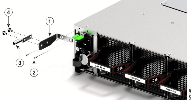
| ||||||||
Step 5 | Tighten the Phillips pan-head screws to torque value of 13.25 in-lbs (1.5 N-m). | ||||||||
Step 6 | Ensure that the lug and cable do not interfere with other equipment. | ||||||||
Step 7 | Prepare the other end of the grounding cable, and connect it to an appropriate grounding point in your site to ensure adequate earth ground. |
Install the rack
Before you install the switch, you must install a standard four-post, 19-inch EIA data center rack (or a cabinet that contains such a rack) that meets the requirements.
-
Install the switch in these types of cabinets and racks, assuming an external ambient air temperature range of 0 to 104°F (0 to 40°C):
- Standard perforated cabinets
- Solid-walled cabinets with a roof fan tray (bottom to top cooling)
- Standard open racks
If you are using an enclosed cabinet, we recommend that you use one of the thermally validated types, either standard perforated or solid-walled with a fan tray.
We do not recommend using racks that have obstructions (such as power strips). The obstructions could impair access to field-replaceable units (FRUs).
Safety warnings
Adhere to these safety warnings before you rack mount the switch.
WarningStatement 1006—Chassis Warning for Rack-Mounting and Servicing
To prevent bodily injury when mounting or servicing this unit in a rack, you must take special precautions to ensure that the system remains stable. The following guidelines are provided to ensure your safety:
- This unit should be mounted at the bottom of the rack if it is the only unit in the rack.
- When mounting this unit in a partially filled rack, load the rack from the bottom to the top with the heaviest component at the bottom of the rack.
- If the rack is provided with stabilizing devices, install the stabilizers before mounting or servicing the unit in the rack.
WarningStatement 1032—Lifting the Chassis
To prevent personal injury or damage to the chassis, never attempt to lift or tilt the chassis using the handles on modules, such as power supplies, fans, or cards. These types of handles are not designed to support the weight of the unit.
WarningStatement 1074—Comply with Local and National Electrical Codes
To reduce risk of electric shock or fire, installation of the equipment must comply with local and national electrical codes.
Install a 4-post rack
This section describes how to install the standard four-post rack.
Step 1 | Bolt the rack to the concrete subfloor before moving the chassis onto it.
|
Step 2 | If the rack has bonded construction, connect it to the earth ground. This action enables you to easily ground the switch and its components and to ground your electrostatic discharge (ESD) wrist strap to prevent damaging discharges when you handle ungrounded components before installing them. |
Step 3 | Include one or two power sources at the rack. For AC power, provide a power receptacle. |
Step 4 | Include one or two power sources at the rack. For DC power, provide a circuit breaker with terminals for connecting power cables. If you are not using power redundancy or are using n+1 redundancy, you need only one power source. If you are using n+n redundancy, you need two power sources. |
Attach the switch in a 4-post rack
NoteIf the rack is on wheels, ensure that the brakes are engaged or that the rack is otherwise stabilized.
Perform this task to install the switch in a 4-post rack.
This table provides the list of tools available in the 4-post rack-mount kit.
|
Quantity |
Description |
|---|---|
|
1 |
Grounding lug and screws |
|
19 |
M3 x 6 mm Phillips flat-head screws |
|
12 |
M4 x 6 mm Phillips flat-head screws |
|
2 |
M4 x 6 mm Phillips pan-head screws |
|
2 |
Rack mount brackets |
|
2 |
Rack-mount guides |
|
2 |
Rack-mount guide rails |
NoteThis switch does not support port-side exhaust configuration.
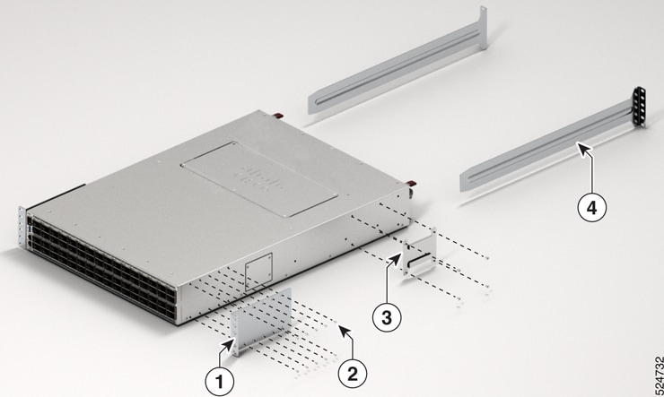
Slide the chassis onto the bottom-support rails so that the power supply end locks onto the chassis stops at the end of the rails and so that the front-mount brackets on the chassis come into contact with the front-mount rails on the rack.
Step 1 | Install the rack-mount brackets to the switch:
| ||||||||
Step 2 | Install the two rack-mount guides on the chassis.
| ||||||||
Step 3 | Install the guide rails to the rack.
| ||||||||
Step 4 | Insert the switch into the rack and attach the switch.
|
After switch installation HF6100-64ED
Step 1 | Turn on the power supply switches to power up the system. While powering up, the switch performs a series of bootup diagnostic tests. NoteThe switch is designed to boot up in less than 30 minutes, provided that the neighboring devices are in fully operational state. |
Step 2 | Connect the required devices to the switch ports. |
Step 3 | Verify port connectivity after connecting devices to the switch ports. The LED turns green when the switch and the attached device have a link. |