
Install the Switch - HF6100-60L4D
Unbox or unpack the switch
Box contents
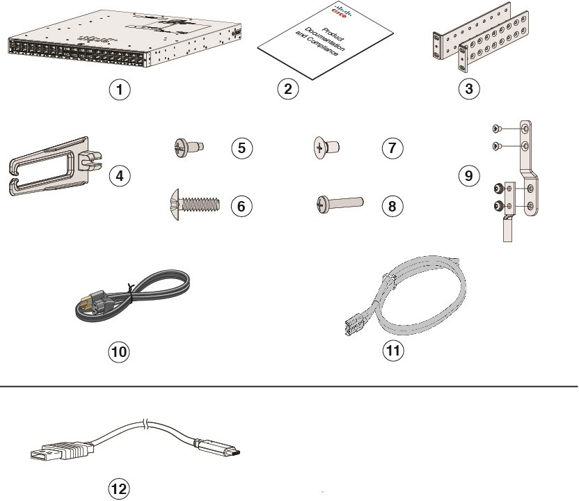
The shipping box contains the model of the switch you ordered and other components needed for installation. Some components are optional, depending on your order.
|
1 |
Cisco Nexus Hyperfabric HF6100-60L4D (power supply and fan modules not shown) |
7 |
12 M4.0 x 6mm Phillips flat-head screws |
|
2 |
Product documentation and compliance document |
8 |
One M4.0 x 20mm Phillips pan-head screw (Black color) |
|
3 |
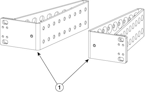
Mounting brackets |
9 |
Ground lug and four M4.0 x 6mm screws (two pan-head and two flat-head screws) |
|
4 |
Cable guide |
10 |
(Optional) AC power cord |
|
5 |
Four number-12 Phillips pan-head 0.50" long screws |
11 |
(Optional) DC power cord |
|
6 |
Four number-10 Phillips pan-head 0.625" long screws |
12 |
(Optional) USB console cable |
Spare accessory kits
The table describes the spare accessory kits supported on different switch models:
|
Part Number |
Description |
|---|---|
|
C9500X-ACCKIT-19I= |
19" rack mount accessory kit |
| C9500X-ACCKIT-23I= | 23" rack mount accessory kit |
| C9500X-4PTH-KIT= | Extension rails and brackets for four-point mounting |
Use the box contents
Do not discard the shipping container when you unpack the switch. Flatten the shipping cartons and store them with the pallet. You will need these containers if you need to move or ship the switch in the future.
Step 1 | Verify that you received all listed equipment:
|
Step 2 | Check the contents of the accessory kit. |
Ground the switch
Installations that rely solely on system grounding using only an AC third-prong ground run a substantially greater risk of equipment problems and data corruption than those installations that use both the AC third-prong ground and a properly installed system ground.
The system ground provides additional grounding for EMI shielding requirements and grounding for the low voltage supplies (DC-DC converters) on the modules. You must observe the following system grounding guidelines for your chassis:
- You must install the system ground connection with any other rack or system power ground connections that you make. The system ground connection is required if modules are installed or if this equipment is installed in a U.S. or European Central Office.
- You must connect both the system ground connection and the power supply ground connection to an earth ground. The system ground connection is required if FXS modules are installed or if this equipment is installed in a U.S. or European Central Office.
- When using DC-input power supplies, you must install the system ground before you attach the source DC power cables to the DC PEM. Power down the chassis before attaching the system ground.
 Note
Note- In all situations, grounding practices must comply with Section 250 of the National Electric Code (NEC) requirements or local laws and regulations. A 6 AWG grounding wire is recommended from the chassis to the rack ground or directly to the common bonding network (CBN). The equipment rack should also be connected to the CBN with 6 AWG grounding wire.
- The system ground serves as the primary safety ground for chassis that are equipped with DC-input power supplies. The DC-input power supplies for these chassis do not have a separate ground.
 Warning
Statement 1024—Ground Conductor
This equipment must be grounded. To reduce the risk of electric shock, never defeat the ground conductor or operate the equipment in the absence of a suitably installed ground conductor. Contact the appropriate electrical inspection authority or an electrician if you are uncertain that suitable grounding is available.
WarningStatement 1046—Installing or Replacing the Unit
To reduce risk of electric shock, when installing or replacing the unit, the ground connection must always be made first and disconnected last.
If your unit has modules, secure them with the provided screws.
Required tools and equipment
To connect the system ground, you need the following tools and materials:
- Grounding lug — When using the double-hole lug connector provided with the system, the ground wire must be 6 AWG only. Otherwise, a supported closed-loop ring connector must be used for 8-14 AWG wire.
- Grounding screws — Two M4.0 x 6mm Phillips pan-head screws. Supplied as part of the accessory kit.
- Grounding wire — Not supplied as part of accessory kit. The grounding wire should be sized according to local and national installation requirements. For U.S. installations, AC power supply systems require a 14 AWG copper conductor. Commercially available 8-14 AWG wire is recommended. DC power supply systems with 930W power supply module require a 12 AWG wire and 1500W power supply module require a 8 AWG wire. The length of the grounding wire depends on the proximity of the switch to proper grounding facilities.
- No. 1 Phillips screwdriver.
- Crimping tool to crimp the grounding wire to the grounding lug.
- Wire-stripping tool to remove the insulation from the grounding wire.
Connect the switch to ground
To establish an earth ground for the chassis, you must attach a grounding cable from the chassis’ grounding lug to the rack.
Step 1 | Use a wire-stripping tool to remove approximately 0.75 inch (19 mm) of the covering from the end of the grounding wire. | ||||||||
Step 2 | Insert the stripped end of the grounding wire into the open end of the grounding lug. | ||||||||
Step 3 | Crimp the grounding wire in the barrel of the grounding lug. Verify that the ground wire is securely attached to the ground lug. | ||||||||
Step 4 | Place the grounding wire lug against the grounding pad on the switch, making sure that there is solid metal-to-metal contact. You can install the grounding lug on the left or the right side of the chassis; the grounding pad are located on the sides of the chassis. | ||||||||
Step 5 | Before you secure the lug to the chassis, make sure that the grounding lug and the grounding wire do not interfere with other switch hardware or rack equipment. Secure the grounding bracket and the lug to the chassis with two M4.0x 6mm flat-head screws. 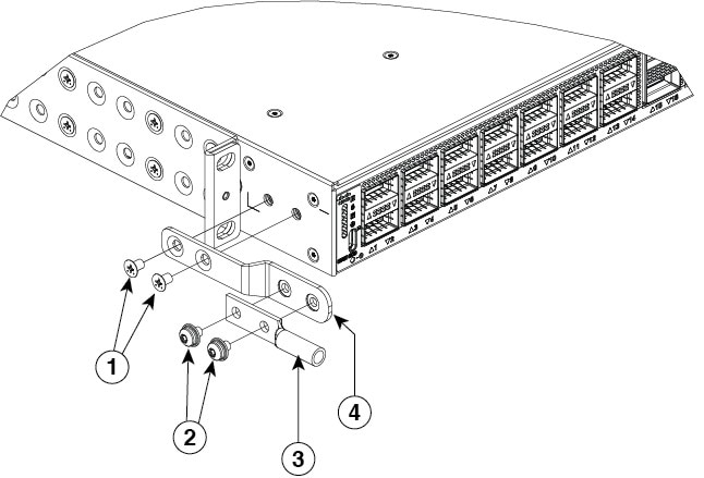
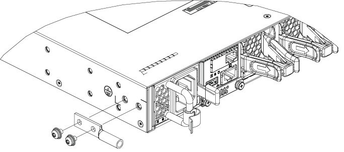
| ||||||||
Step 6 | Prepare the other end of the grounding wire with a ring lug and secure it to the rack with a screw. |
Install the rack
Rack-mounting
- For Network Equipment Building Systems (NEBS) installation, use the four post rack mount kit. The depth of the rack, measured between the front-mounting and the rear-mounting strips must be between 24.72 inches and 39.75 inches.
- Ensure you read the Regulatory Compliance and Safety Information (RCSI) before installing the switch.
- Installation in racks other than 19-inch racks requires a bracket kit not included with the switch.
WarningStatement 1032—Lifting the Chassis
To prevent personal injury or damage to the chassis, never attempt to lift or tilt the chassis using the handles on modules, such as power supplies, fans, or cards. These types of handles are not designed to support the weight of the unit.
WarningStatement 1006—Chassis Warning for Rack-Mounting and Servicing
To prevent bodily injury when mounting or servicing this unit in a rack, you must take special precautions to ensure that the system remains stable. The following guidelines are provided to ensure your safety:
- This unit should be mounted at the bottom of the rack if it is the only unit in the rack.
- When mounting this unit in a partially filled rack, load the rack from the bottom to the top with the heaviest component at the bottom of the rack.
- If the rack is provided with stabilizing devices, install the stabilizers before mounting or servicing the unit in the rack.
|
1 |
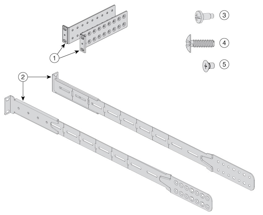
Two 19-inch brackets |
4 |
Eight number-10 Phillips pan-head 0.625" long screws |
|
2 |
Extension rails and brackets for four-point mounting |
5 |
24 M4.0 x 6mm Phillips flat-head screws |
|
3 |
Eight number-12 Phillips pan-head 0.50" long screws |
- |
- |
NoteOrder the optional 23-inch rack mount kit from your Cisco sales representative.
|
1 |
23-inch rack mount bracket |
Attach the rack-mount bracket
Before you begin
Determine which end of the switch should be located in the cold aisle of the site:
-
If the switch supports front-to-back air flow (C9500X-FAN-1U-R fan module), position the switch such that ports are located in the cold aisle.
Position of ports in front-to-back air flow fan 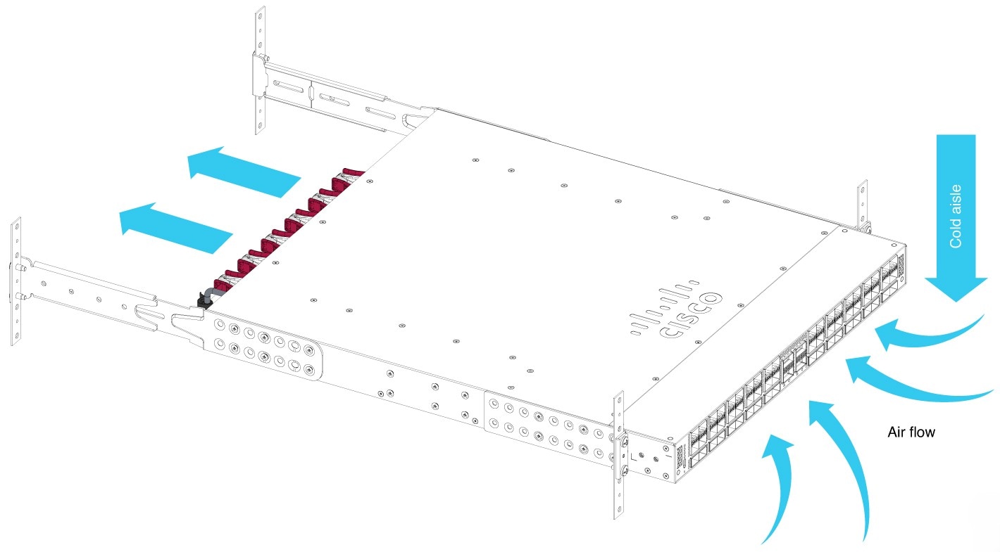
-
If the switch supports back-to-front air flow (C9500X-FAN-1U-F fan module), position the switch such that the fan and power supply modules are located in the cold aisle.
Position of ports in back-to-front air flow fan 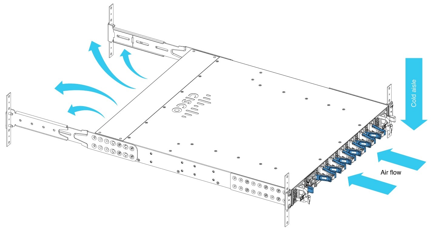
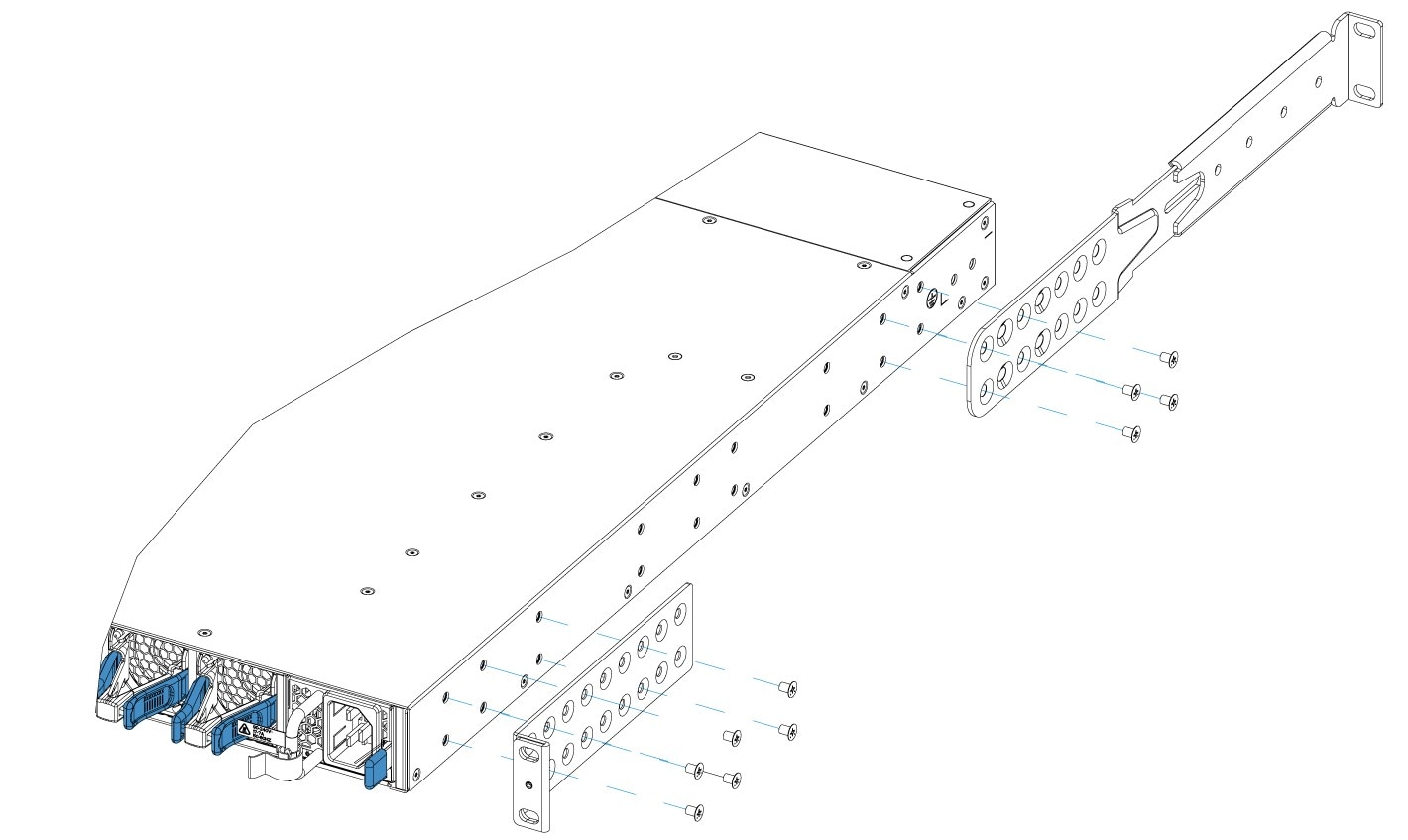
Step 1 | Attach the rack-mount brackets to the switch.
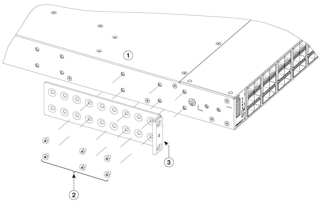
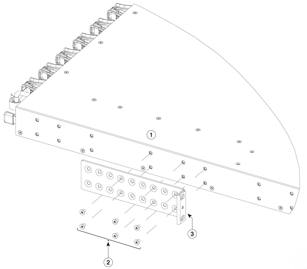
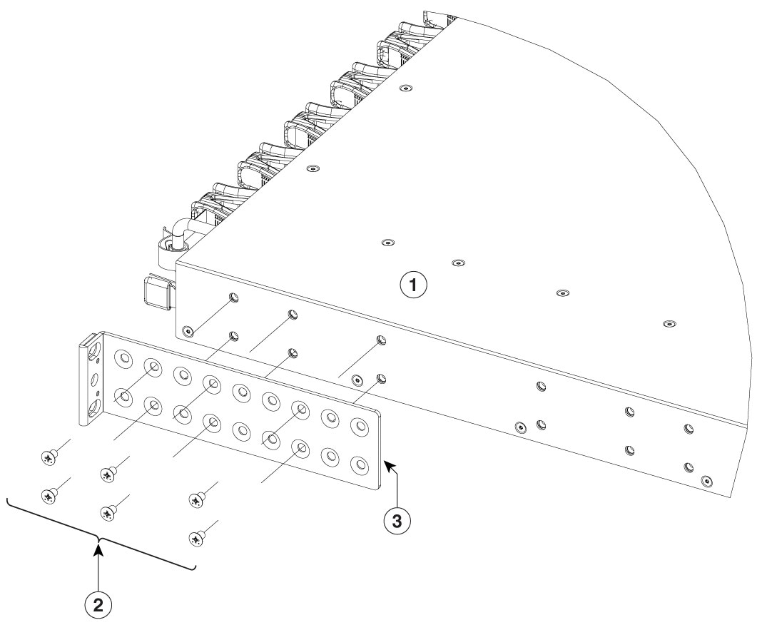
| ||||||||
Step 2 | The extension rail that is provided may be longer than the required size. To trim the extension rail to the required length, bend the extension rail along the mark specified and cut it. 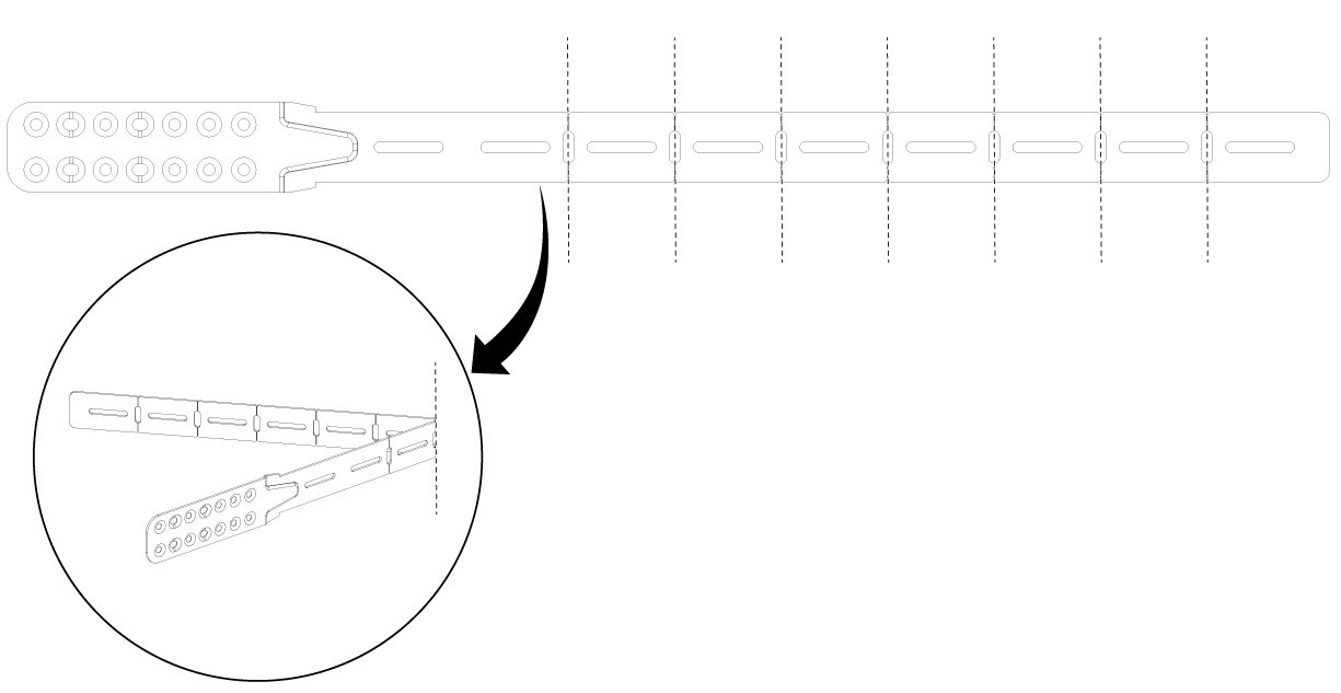 | ||||||||
Step 3 | If the switch ports are located in the cold aisle (front-to-back air flow), use the Phillips machine screws to attach the brackets and the extension rail to the switch.
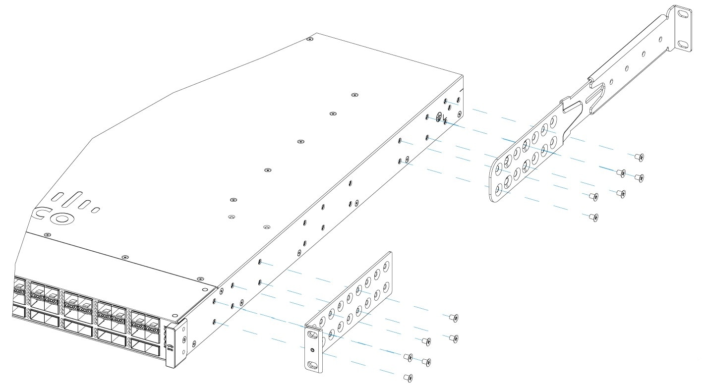 | ||||||||
Step 4 | If the switch ports are located away from the cold aisle (back-to-front air flow):
|

Mount the switch on a rack
Before you begin
- Ensure that the power supply is installed.
- Ensure that the fan is installed.
Step 1 | Use the black Phillips machine screw to attach the cable guide to the left or right bracket. 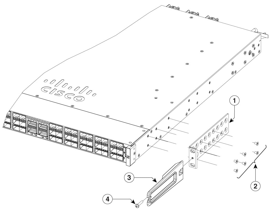
| ||||||||
Step 2 | Secure the switch to the rack rails using the Number-12 or number-10 Phillips machine screws provided with the accessory kit. 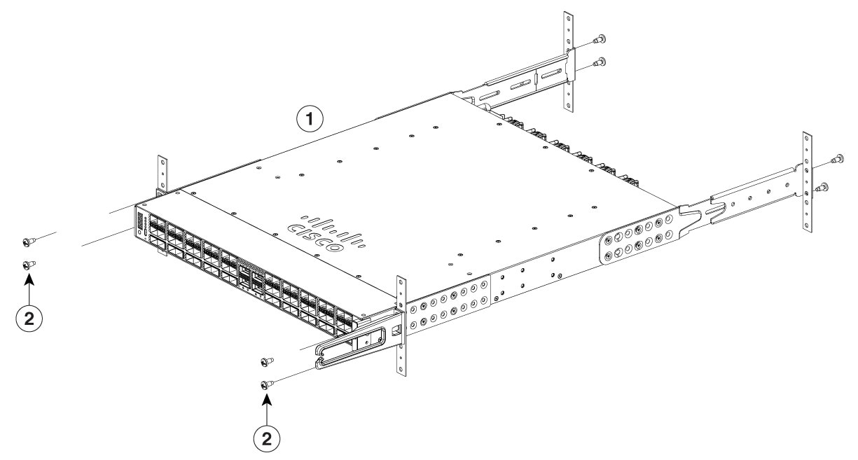
|
After switch installation
Step 1 | Turn on the power supply switches to power up the system. While powering up, the switch performs a series of bootup diagnostic tests. NoteThe switch is designed to boot up in less than 30 minutes, provided that the neighboring devices are in fully operational state. |
Step 2 | Connect the required devices to the switch ports. |
Step 3 | Verify port connectivity after connecting devices to the switch ports. The LED turns green when the switch and the attached device have a link. |
Removing SFP and SFP+ modules from the modular port card
The removal of SFP and SFP+ modules require the optics extraction tool from the C9K-OPTICS-TOOL= kit.
Step 1 | Attach an ESD-preventive wrist strap to your wrist and to an earth ground surface. |
Step 2 | The module has a bale-clasp latch, use the SFP removal tool. Use the optical cable release side of the tool and apply pressure to release the cable latch, and disconnect the cable from the SFP transceiver module. |
Step 3 | Use the bale-release latch side of the tool to lift the bale up, and remove the SFP or SFP+ module. |
Step 4 | Grasp the SFP or SFP+ transceiver module, and carefully remove it from the slot. |
Step 5 | Place the SFP or SFP+ transceiver module in an antistatic bag or other protective environment. |