
Install the Switch - HF6100-32D
Unbox or unpack the switch
Box contents
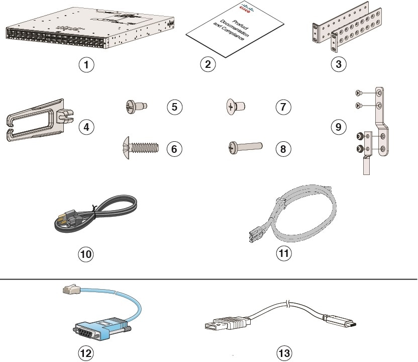
The shipping box contains the model of the switch you ordered and other components needed for installation. Some components are optional, depending on your order.
|
1 |
Cisco Nexus Hyperfabric HF6100-32D (power supply and fan modules not shown) |
8 |
One M4.0 x 20mm Phillips pan-head screw (Black color) |
|
2 |
Product documentation and compliance document |
9 |
Ground lug and four M4.0 x 6mm screws (two pan-head and two flat-head screws) |
|
3 |
Mounting brackets |
10 |
(Optional) AC power cord |
|
4 |
Cable guide |
11 |
(Optional) DC power cord |
|
5 |
Four number-12 Phillips pan-head 0.50" long screws |
12 |
(Optional) RJ-45 console cable |
|
6 |
Four number-10 Phillips pan-head 0.625" 4 long screws |
13 |
(Optional) USB console cable |
|
7 |
12 M4.0 x 6mm Phillips flat-head screws |
- |
- |
Use the box contents
Do not discard the shipping container when you unpack the switch. Flatten the shipping cartons and store them with the pallet. You will need these containers if you need to move or ship the switch in the future.
Step 1 | Verify that you received all listed equipment:
|
Step 2 | Check the contents of the accessory kit. |
Ground the switch
Installations that rely solely on system grounding using only an AC third-prong ground run a substantially greater risk of equipment problems and data corruption than those installations that use both the AC third-prong ground and a properly installed system ground.
The system ground provides additional grounding for EMI shielding requirements and grounding for the low voltage supplies (DC-DC converters) on the modules. You must observe the following system grounding guidelines for your chassis:
- You must install the system ground connection with any other rack or system power ground connections that you make. The system ground connection is required if modules are installed or if this equipment is installed in a U.S. or European Central Office.
- You must connect both the system ground connection and the power supply ground connection to an earth ground. The system ground connection is required if FXS modules are installed or if this equipment is installed in a U.S. or European Central Office.
- When using DC-input power supplies, you must install the system ground before you attach the source DC power cables to the DC PEM. Power down the chassis before attaching the system ground.
 Note
Note- In all situations, grounding practices must comply with Section 250 of the National Electric Code (NEC) requirements or local laws and regulations. A 6 AWG grounding wire is recommended from the chassis to the rack ground or directly to the common bonding network (CBN). The equipment rack should also be connected to the CBN with 6 AWG grounding wire.
- The system ground serves as the primary safety ground for chassis that are equipped with DC-input power supplies. The DC-input power supplies for these chassis do not have a separate ground.
Required tools and equipment
To connect the system ground, you need the following tools and materials:
- Grounding lug — When using the double-hole lug connector provided with the system, the ground wire must be 6 AWG only. Otherwise, a supported closed-loop ring connector must be used for 8-14 AWG wire.
- Grounding screws — Two M4.0 x 6mm Phillips pan-head screws. Supplied as part of the accessory kit.
- Grounding wire — Not supplied as part of accessory kit. The grounding wire should be sized according to local and national installation requirements. For U.S. installations, AC power supply systems require a 14 AWG copper conductor. Commercially available 8-14 AWG wire is recommended. DC power supply systems with 930W power supply module require a 12 AWG wire and 1500W power supply module require a 8 AWG wire. The length of the grounding wire depends on the proximity of the switch to proper grounding facilities.
- Number 1 and number 2 Phillips screwdrivers with torque capability to rack-mount the chassis.
- 3/16-inch flat-blade screwdriver.
- Tape measure and level.
- ESD wrist strap or other grounding device.
- Antistatic mat or antistatic foam.
- Two-hole ground lug (1).
- Grounding cable sized according to local and national installation requirements; the required length depends on the proximity of the switch to proper grounding facilities. Cisco provides a 6 AWG lug.
- Crimping tool for lug.
- Wire-stripping tool.
- M4 screws to fix brackets (16).
- M4 screws to fix a ground lug (2).
Connect the switch to the ground
To establish an earth ground for the chassis, you must attach a grounding cable from the chassis’ grounding lug to the rack.
Step 1 | Use a wire-stripping tool to remove approximately 0.75 inch (19 mm) of the covering from the end of the grounding wire. | ||||
Step 2 | Insert the stripped end of the grounding wire into the open end of the grounding lug. | ||||
Step 3 | Crimp the grounding wire in the barrel of the grounding lug. Verify that the ground wire is securely attached to the ground lug. | ||||
Step 4 | Place the grounding wire lug against the grounding pad on the switch, making sure that there is solid metal-to-metal contact. You can install the grounding lug on the left or the right side of the chassis; the grounding pad are located on the sides of the chassis. | ||||
Step 5 | Before you secure the lug to the chassis, make sure that the grounding lug and the grounding wire do not interfere with other switch hardware or rack equipment. Secure the grounding bracket and the lug to the chassis with two M4.0x 6mm flat-head screws. 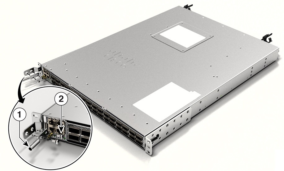
| ||||
Step 6 | Tighten the pan-head screws to torque value of 13.25 in-lbs (1.5 N-m). | ||||
Step 7 | Ensure that the lug and cable do not interfere with other equipment. | ||||
Step 8 | Prepare the other end of the grounding wire with a ring lug and secure it to the rack with a screw. |
Install the rack
Rack installation guidelines
Before installing the chassis, ensure that the following guidelines are met:
- Site is properly prepared so that there is sufficient room for installation and maintenance.
- Operating environment is within the ranges that are listed in Environment and Physical specifications.
- Chassis is mounted at the bottom of the rack if it is the only unit in the rack.
- When mounting the chassis in a partially filled rack, load the rack from the bottom to the top with the heaviest component at the bottom of the rack.
- If the rack is provided with stabilizing devices, install the stabilizers before mounting or servicing the chassis in the rack.
- Airflow around the chassis and through the vents is unrestricted.
- Cabling is away from sources of electrical noise, such as radios, power lines, and fluorescent lighting fixtures. Make sure that the cabling is safely away from other devices that might damage the cables.
- Each port must match the wave-length specifications on each end of the cable, and the cable must not exceed the stipulated cable length.
- Port-side exhaust configuration is not supported.
NoteFor fixed-port routers that support port side exhaust fans and power supplies, the maximum temperature is reduced by 5°C (for example, 35°C at sea level or 30°C at 1500 meters).
Rack-mounting
The list of supported Rackmount configurations are as follows.
|
Rackmount PIDs |
Description |
Availability |
Post Support |
Rackmount Bracket Position |
Rack Width Support |
Rack Depth Support |
|---|---|---|---|---|---|---|
|
N9K-ACC-KIT-1RU-S |
19" rackmount 4-post kit, short |
Optional |
4 post |
Front and Rear |
19” |
23.365 in. to 29.615 in. (59.3 cms to 75.2 cms) |
|
N9K-ACC-KIT-1RU-L |
19" rackmount 4-post kit, long |
Always Included |
4 post |
Front and Rear |
19” |
29.615 in. to 35.865 in. (75.2 cms to 91.1 cms) |
|
C9500X-ACCKIT-19I= |
19" rackmount 2-post kit |
Always Included |
2 post |
Middle Mount Only |
19” |
Any |
|
C9500X-ACCKIT-23I= |
23" rackmount 2-post kit |
Optional |
2 post |
Middle Mount Only |
23” |
Any |
- For Network Equipment Building Systems (NEBS) installation, use the four post rack mount kit. The depth of the rack, measured between the front-mounting and the rear-mounting strips must be between 24.72 inches and 39.75 inches.
- Ensure you read the Regulatory Compliance and Safety Information (RCSI) before installing the switch.
- Installation in racks other than 19-inch racks requires a bracket kit not included with the switch.
NoteTo prevent bodily injury when mounting or servicing this unit in a rack, you must take special precautions to ensure that the system remains stable. The following guidelines are provided to ensure your safety:
- This unit should be mounted at the bottom of the rack if it is the only unit in the rack.
- When mounting this unit in a partially filled rack, load the rack from the bottom to the top with the heaviest component at the bottom of the rack.
- If the rack is provided with stabilizing devices, install the stabilizers before mounting or servicing the unit in the rack.
Statement 1006
NoteTo reduce risk of electric shock and fire, take care when connecting units to the supply circuit so that wiring is not overloaded.
Statement 1018
|
1 |
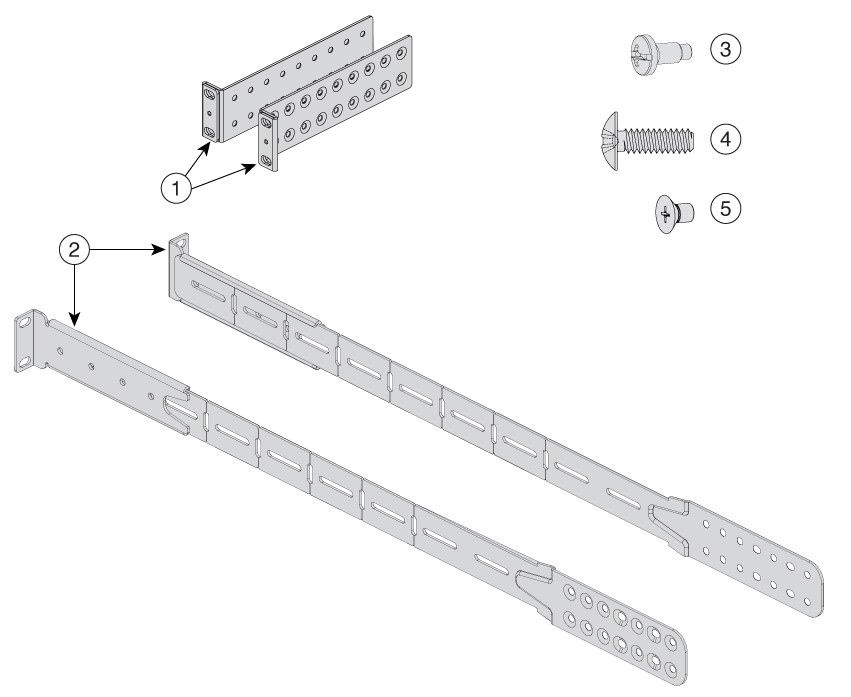
Two 19-inch brackets |
4 |
Eight number-10 Phillips pan-head 0.625" long screws |
|
2 |
Extension rails and brackets for four-point mounting |
5 |
24 M4.0 x 6mm Phillips flat-head screws |
|
3 |
Eight number-12 Phillips pan-head 0.50" long screws |
- |
- |
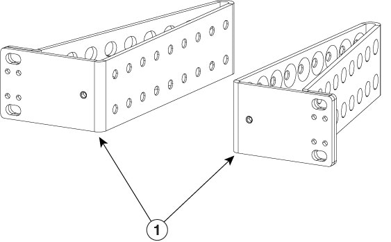
NoteOrder the optional 23-inch rack mount kit from your Cisco sales representative.
|
1 |
23-inch rack mount bracket |
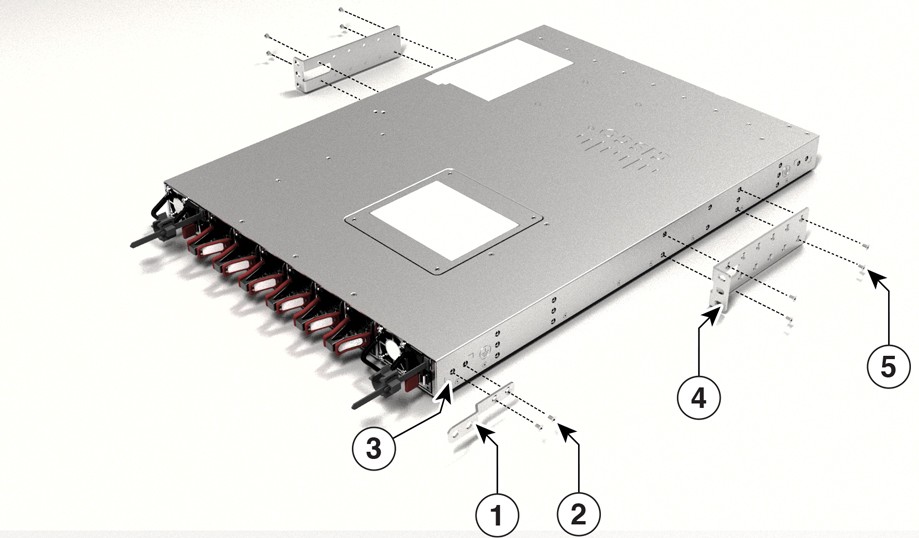
Attach the rack-mount bracket
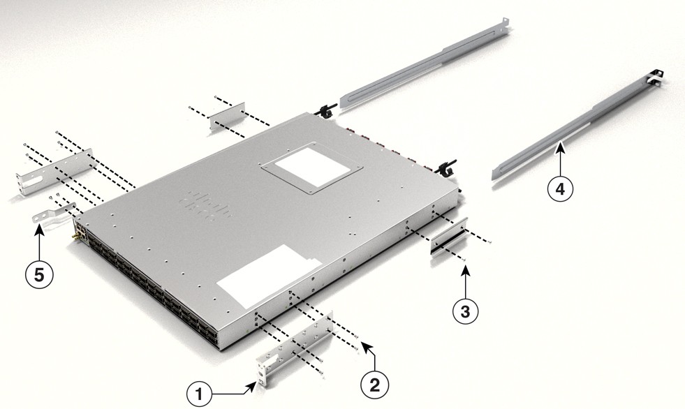
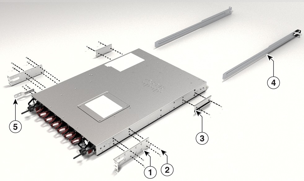
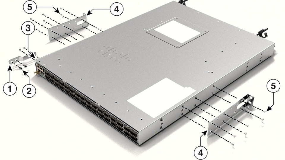
Step 1 | Attach the rack-mount brackets to the switch.
| ||||||||||||
Step 2 | The extension rail that is provided may be longer than the required size. To trim the extension rail to the required length, bend the extension rail along the mark specified and cut it. 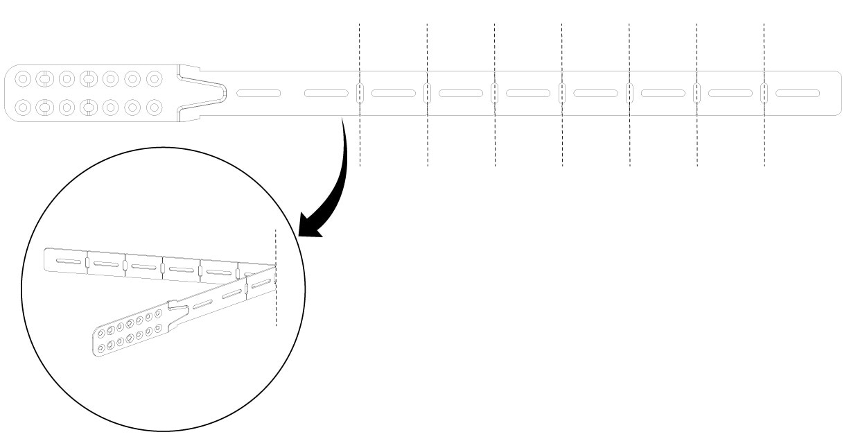
| ||||||||||||
Step 3 | If the switch ports are located in the cold aisle (front-to-back air flow), use the Phillips machine screws to attach the brackets and the extension rail to the switch. Use six screws to attach the extension rail on to one side of the switch. |
Mount the switch on a rack
- Ensure that the power supply is installed.
- Ensure that the fan is installed.
Step 1 | Use the black Phillips machine screw to attach the cable guide to the left or right bracket. 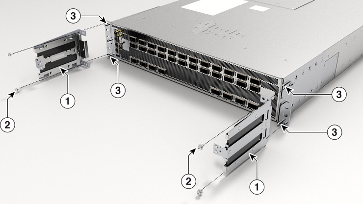
| ||||||||
Step 2 | Secure the switch to the rack rails using the Number-12 or number-10 Phillips machine screws provided with the accessory kit. |
After switch installation HF6100-32D
Step 1 | Turn on the power supply switches to power up the system. While powering up, the switch performs a series of bootup diagnostic tests. NoteThe switch is designed to boot up in less than 30 minutes, provided that the neighboring devices are in fully operational state. |
Step 2 | Connect the required devices to the switch ports. |
Step 3 | Verify the port connectivity after connecting devices to the switch ports. The LED turns green when the switch and the attached device have a link. |
Step 4 | Configure the switch using the User Interface. For more information, see "Configuring the Switch Using the Web User Interface" topic in the Software Configuration Guide. |