
Install the Power Supply - HF6100-64ED
Overview
Cisco HF6100-64ED has two internal power supply module slots. You can either use one or two power supply modules. All empty power supply module slots must be filled with a blank module.
These power supply module slots accept AC and DC input power supplies. The power supply modules are hot-swappable.
This table lists the power supply models supported by the switch.
|
Part number |
PSU module |
|---|---|
|
PSU3KW-HVPI |
3000-Watts AC/DC power module with port-side air intake |
Two combinations of power supply are possible.
- Two AC, two DC, or AC-DC power supplies
- One AC-input power supply or one DC-input power supply (leaving the blank cover on the other slot)
 Note
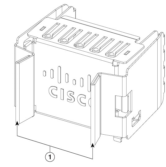
NoteIf you leave any power supply slots empty, you must ensure that the blank cover (PWR-C6-BLANK) is installed in that slot to maintain the designed airflow.
The airflow for the power supply is
- unidirectional, and
- port-side intake airflow: the airflow through both the fan trays and power supplies is from the front-side to the rear-side. In PSI configuration, the power and fan modules are in Burgundy color.
Power supply models HF6100-64E
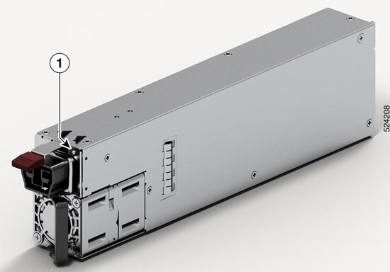
This illustration shows the 3000 W AC power supply, PSU3KW-HVPI.
|
1 |
PSU LED |
- |
- |
|
1 |
Release handles |
Power supply modules LEDs
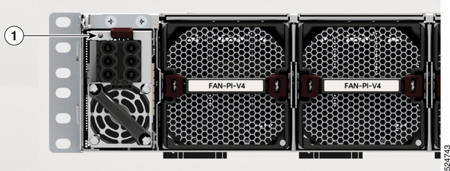
This section describes the power supply module LEDs.
|
1 |
Status LED |
This table describes the power supply LED colors and what each color denotes.
|
Color |
Status |
|---|---|
|
Amber |
Power supply failure; can be due to out-of-band voltage, current, or temperature, or fan failure. |
|
Flashing amber |
Power supply is operating, but a warning condition has occurred; can be due to high temperature, high current, or slow fan speed. |
|
Green |
Power supply is active and power is being delivered to the device. |
|
Off |
Power supply is not receiving power. |
Power supply installation guidelines
Ensure that you comply with these safety warnings.
 Warning
Statement 1003—DC Power Disconnection
To reduce risk of electric shock or personal injury, disconnect DC power before removing or replacing components or performing upgrades.
WarningStatement 1005—Circuit Breaker
This product relies on the building’s installation for short-circuit (overcurrent) protection. To reduce risk of electric shock or fire, ensure that the protective device is rated not greater than:
- 20 A (North America) and 16 A (Europe) circuit breaker for an AC-input power supply module. 83 A DC-rated circuit breaker for each input of a DC-input power supply module, for safety purposes - irrespective of whether the inputs are power from a single or separate DC sources.
WarningStatement 1022—Disconnect Device
To reduce the risk of electric shock and fire, a readily accessible disconnect device must be incorporated in the fixed wiring.
WarningStatement 1024—Ground Conductor
This equipment must be grounded. To reduce the risk of electric shock, never defeat the ground conductor or operate the equipment in the absence of a suitably installed ground conductor. Contact the appropriate electrical inspection authority or an electrician if you are uncertain that suitable grounding is available.
WarningStatement 1028—More Than One Power Supply
This unit might have more than one power supply connection. To reduce risk of electric shock, remove all connections to de-energize the unit.
 Warning
Statement 1033—Safety Extra-Low Voltage (SELV)—IEC 60950/ES1–IEC 62368 DC Power Supply
To reduce the risk of electric shock, connect the unit only to a DC power source that complies with the SELV requirements in the IEC 60950-based safety standards or the ES1 requirements in the IEC 62368-based safety standards.
WarningStatement 1046—Installing or Replacing the Unit
To reduce risk of electric shock, when installing or replacing the unit, the ground connection must always be made first and disconnected last.
If your unit has modules, secure them with the provided screws.
WarningStatement 1090—Installation by Skilled Person
Only a skilled person should be allowed to install, replace, or service this equipment. See statement 1089 for the definition of a skilled person.
Guidelines for DC power supply units
- All power connection wiring should conform to the rules and regulations prescribed by the National Electrical Code (NEC), as well as local codes, if any.
- The DC return must remain isolated from the system frame and the chassis (DC-I). The color coding of the source DC power cable leads depends on the color coding of the site DC power source. Typically, green or green and yellow stripes indicate that the cable is a ground cable. Since there is no color code standard for source DC wiring, you must ensure that the power cables are connected to the DC-input power supply terminal block in the proper + and - polarity. In some cases, the source DC cable leads might have a positive (+) or a negative (–) label. This label is a relatively safe indication of polarity, but you must verify the polarity by measuring the voltage between the DC cable leads. When measuring, ensure that the positive lead and the negative lead always match the "+" and "-" labels on the DC-input power supply terminal block, respectively.
- DC power cables use the M-CRPS connector at the power supply end.
- The circuit must be protected by a dedicated two-pole DC-rated circuit breaker. The circuit breaker is considered to be the disconnect device and must be easily accessible. For DC-input power supply units with multiple inputs, each DC input must be protected by a dedicated DC-rated circuit breaker or a fuse. The circuit breaker or fuse should be sized according to the power supply input rating and local or national code requirements.
- If the DC inputs are powered from separate sources, the cables must be wired straight across to their respective sources and terminals. Crossed cables in a setup where the DC source has floating outputs means that no damage will occur, but the LEDs will not light up, and the module will not operate. Crossed cables in a setup with a positive ground or a negative ground power system constitute a severe safety hazard that includes causing electric shock and generating excessive EMI and RFI.
Considerations before installing the PSUs
- Use only one type of power supply in the switch.
- The power supply type that is used in the switch depends on the type and configuration of the transceivers installed in it.
- Do not install a mix of AC and DC power supplies.
- The airflow direction must be the same for all power supply and fan modules in the switch.
- The system requires two power supply units for redundancy.
Install power supply modules
Perform this task to install power supply units on HF6100-64ED.
Step 1 | Remove the blank cover and store it for future use. |
Step 2 | Verify that the power supply is not connected to any power sources. |
Step 3 | Hold the handle on the power supply with one hand and position the power supply with its back end at the open power supply bay. |
Step 4 | Slide the unit all the way into the power supply bay until the release latch on the front of the power supply clicks and prevents you from moving the power supply in or out of the chassis. NoteEnsure that the power supply in inserted into the slot in the right direction. If you have inserted the power supply in the reverse direction, the power supply will not be seated correctly and it projects out of the slot. |
Connect to a power source
Each power cable is shipped with mating connectors with one of the connectors on the power socket and the other connector on the front panel of the power supply. Follow the same steps to install the AC-input and DC-input power supplies; but you must ground them differently.
- AC-input power supply: Is automatically grounded when you connect its power cable to the power supply and the power source.
- DC-input power supply: Do not connect the power supply directly to the earth ground.
Use one power cord per power supply to connect the power supply to its power source.
Connect to an AC power source
Perform this task to connect the power supply units to an AC power source.
Before you begin
 Caution
The chassis relies on the protective devices in the building installation to protect against short circuit, overcurrent, and ground faults. Ensure that the protective devices comply with local and national electrical codes.
NoteWe recommend that you install power supply units in both the power supply slots of the switch. In case a power module fails, it is recommended to retain the failed power module in its slot until it is replaced with a new power module. This recommendation ensures that the system airflow is not impacted adversely, which may then result in the overheating of the switch and its components.
Step 1 | Verify that the AC cable is installed in the correct AC source and outlet type. | ||||
Step 2 | Attach the AC power cable to the AC input of the AC power module. | ||||
Step 3 | Place the cable through the opening in the cable clamp or cable retainer. | ||||
Step 4 | Slide the cable clamp or the cable retainer toward the plug. | ||||
Step 5 | Close the cable clamp or cable retainer on the shoulder of the power cable to secure the power cable. Connecting AC power 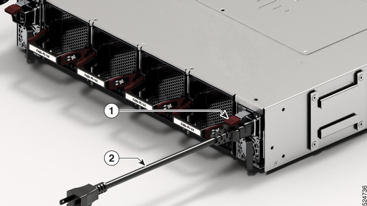
These switches are designed to boot up in less than 30 minutes, provided the neighboring devices are in fully operational. |
Connect high voltage power supply units to a power source
Perform this task to connect high voltage power supply units to a power supply.
Before you begin
The high voltage PSU3KW-HVPI accepts AC, HVAC, or HVDC input power. The HVPI power supply has Anderson power connector for Saf-D-Grid T-latch power cord that can be used for AC, HVAC, or HVDC power.
Step 1 | Choose your power source (AC, HVAC, or HVDC) and use the Saf-D-Grid T-latch power cord to connect to the PSU. NoteTo remove the Saf-D-Grid power cord from the power supply, press the latch before pulling the power cord out. 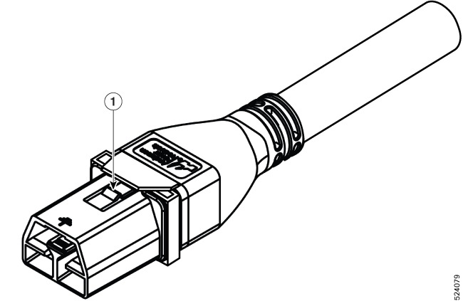
| ||||
Step 2 | Verify that the Saf-D-Grid plug is plugged in completely to secure the built-in retaining latch. 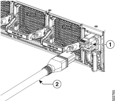
| ||||
Step 3 | Switch on the circuit breaker for the AC, HVAC, or HVDC power source circuit. |
AC input power cords
This table lists the input and output power ranges for PSU high line applications.
|
Locale |
Part number |
Length |
Rating |
|---|---|---|---|
|
Australia, New Zealand |
CAB-AC-10A-ANZ |
14 ft (4.26 m) |
0A, 250 VAC |
|
Brazil |
CAB-AC-10A-BRZ |
14 ft (4.26 m) |
0A, 250 VAC |
|
China |
CAB-AC-10A-CHN |
14 ft (4.26 m) |
0A, 250 VAC |
|
Denmark |
CAB-AC-10A-DEN |
14 ft (4.26 m) |
0A, 250 VAC |
|
Europe |
CAB-AC-10A-EU |
14 ft (4.26 m) |
0A, 250 VAC |
|
Great Britain |
CAB-AC-10A-GBR |
14 ft (4.26 m) |
0A, 250 VAC |
|
Italy |
CAB-AC-10A-ITA |
14 ft (4.26 m) |
0A, 250 VAC |
|
Japan |
CAB-AC-10A-JPN1 |
14 ft (4.26 m) |
0A, 250 VAC |
|
Japan |
CAB-AC-10A-JPN2 |
14 ft (4.26 m) |
0A, 250 VAC |
|
Korea |
CAB-AC-10A-KOR |
14 ft (4.26 m) |
0A, 250 VAC |
|
North America |
CAB-AC-10A-NA |
14 ft (4.26 m) |
0A, 250 VAC |
|
Switzerland |
CAB-AC-10A-CHE |
14 ft (4.26 m) |
0A, 250 VAC |
High-voltage input power cords
This table lists the high-voltage input power cords used by HF6100-64ED.
|
Locale |
Part Number |
Length |
Power cord rating |
|---|---|---|---|
|
Argentina |
CAB-AC-16A-SG-AR |
14 ft (4.26 m) |
16A, 250 VAC |
|
Australia |
CAB-AC-16A-SG-AZ |
14 ft (4.26 m) |
16A, 250 VAC |
|
Brazil |
CAB-AC-16A-SG-BR |
14 ft (4.26 m) |
16A, 250 VAC |
|
China |
CAB-AC-16A-SG-CH |
14 ft (4.26 m) |
16A, 250 VAC |
|
China |
CAB-AC-16A-CN |
14 ft (4.26 m) |
16A, 250 VAC |
|
Europe |
CAB-AC-16A-SG-EU |
14 ft (4.26 m) |
16A, 250 VAC |
|
India |
CAB-AC-16A-SG-IND |
14 ft (4.26 m) |
16A, 250 VAC |
|
International/ UK |
CAB-AC-16A-SG-IN |
14 ft (4.26 m) |
16A, 250 VAC |
|
Israel |
CAB-AC-16A-SG-IS |
14 ft (4.26 m) |
16A, 250 VAC |
|
Italy |
CAB-AC-16A-SG-IT |
14 ft (4.26 m) |
16A, 250 VAC |
|
Japan |
CAB-AC-16A-SG-JPN |
14 ft (4.26 m) |
16A, 250 VAC |
|
South Africa |
CAB-AC-16A-SG-SA |
14 ft (4.26 m) |
16A, 250 VAC |
|
South Korea |
CAB-AC-16A-SG-SK |
14 ft (4.26 m) |
16A, 250 VAC |
|
Switzerland |
CAB-AC-16A-SG-SW |
14 ft (4.26 m) |
16A, 250 VAC |
|
United Kingdom |
CAB-AC-16A-SG-UK |
14 ft (4.26 m) |
16A, 250 VAC |
|
North America (non locking) 110 VAC operation |
CAB-AC-20A-SG-US |
14 ft (4.26 m) |
20A, 110 VAC |
|
North America (locking) 125 VAC operation |
CAB-AC-20A-SG-US1 |
14 ft (4.26 m) |
20A, 125 VAC |
|
North America (non locking) 200-240 VAC operation |
CAB-AC-20A-SG-US2 |
14 ft (4.26 m) |
20A, 250 VAC |
|
North America (locking) 200-240 VAC operation |
CAB-AC-20A-SG-US3 |
14 ft (4.26 m) |
20A, 250 VAC |
|
North America 277 VAC operation |
CAB-AC-20A-SG-US4 |
14 ft (4.26 m) |
20A, 277 VAC |
|
North America Cabinet Jumper Power Distribution unit (PDU) |
CAB-AC-20A-SG-C20 |
14 ft (4.26 m) |
20A, 250 VAC |
|
North America, Ring Terminal source plug |
CAB-HV-25A-SG-US2 |
14 ft (4.26 m) |
20A, 300 VAC/500 VDC |
|
International IEC/EU, Ring Terminal source plug |
CAB-HV-25A-SG-IN2 |
14 ft (4.26 m) |
20A, 300 VAC/500 VDC |