Install the Fan HF6100-64ED
Overview
The fan tray assembly in HF6100-64ED series switches have four fan trays with one fan each at the rear of the switch. The fan modules are designed to be removed and replaced while the system is operating without presenting an electrical hazard or damage to the system. Please keep the replacement fan modules ready prior to attempting this task.
|
Product ID |
Description |
|---|---|
|
FAN-PI-V4 |
Port-side intake airflow |
When the fan modules are operating properly, a green LED at the bottom-right corner of the fan assembly (viewed from the rear), is ON. If a fan module fails, the LED turns to amber. The switch can operate with three operational fans, but the failed fan should be replaced as soon as possible to avoid a service interruption due to a second fan fault.
The fans are responsible for cooling the switch and interfacing with environmental monitors to trigger alarms when conditions exceed thresholds. The fan tray provides cooling that is critical for the switch operation, which could otherwise result in the switch being non-operational or causing permanent damage to modules or components.
Features of the fan
The features of an HF6100-64ED fan tray include
- 4x 80mm fans
- Rear accessible fan units
- Speed of each fan tray is individually controllable
- Supports N+1 redundancy
Fan installation guidelines
Install a fan
Perform this task to replace a fan that is not operational or not working properly.
Before you begin
- The replacement fan module must have the same airflow direction as the other modules in the chassis.
- You must replace the missing fan module within two minutes to avoid a shutdown of the system.
Step 1 | Remove the replacement fan module from its packinging and place it on an antistatic surface. Hold the module by its handle and do not touch the electrical connectors on its backside. Also, to protect the electrical connectors, avoid letting them come in contact with anything other than the electrical connectors inside the chassis. |
Step 2 | Position the fan module in front of the open fan slot. Make sure that the backside of the module with the electrical connectors is positioned to enter the slot first. |
Step 3 | Slide the module all the way into the chassis until its front side comes in contact with the chassis. For the last 0.2 inches (0.5 cm), carefully mount the module onto the chassis connectors by pushing more firmly, but do not force the module if it does not move further (excessive force can damage the connectors).  Note NoteIf you are not able to push the module all the way into the slot, carefully slide the module out of the slot and check its electrical connectors for damage. If damaged, contact Cisco Technical Assistance for help. If undamaged, repeat this step to reinstall the module. |
Step 4 | Verify that the status LED switches on and becomes green. If the status LED does not switch on, slide the module out of the chassis, and visually check the electrical connectors on the back side of the chassis for damage. If damaged, contact Cisco Technical Assistance for help. If undamaged, repeat the previous step to reinstall the module. |
Replace a fan HF6100-64ED
Before you begin
Perform this task to remove a non-operational fan from HF6100-64ED.
Step 1 | Press the two latches on the fan module and grasp the handle of fan module. NoteYou should replace the fan module within 2 minutes to avoid overheating the switch. |
Step 2 | Pull the fan module fully out of the chassis by simultaneously pressing the latches. |
Step 3 | Place the removed fan module on an antistatic surface. |
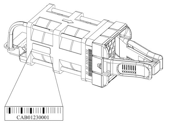
Find the fan serial number
If you contact Cisco Technical Assistance regarding a fan module, you need to know the fan module serial number. See the following illustration to find the serial number.