Capture the Packet with ELAM Assistant
In the welcome screen of ELAM Assistant accessed in Step 1 below, there is the "How To Use" section that shows the steps to use ELAM Assistant. In this document, we explain those steps with more details.
Procedure
|
Step 1 |
Log in to APIC and click Operations > ELAM Assistant. |
||||
|
Step 2 |
Click Initialize in the center of the screen. When done, Ready appears with a check mark. 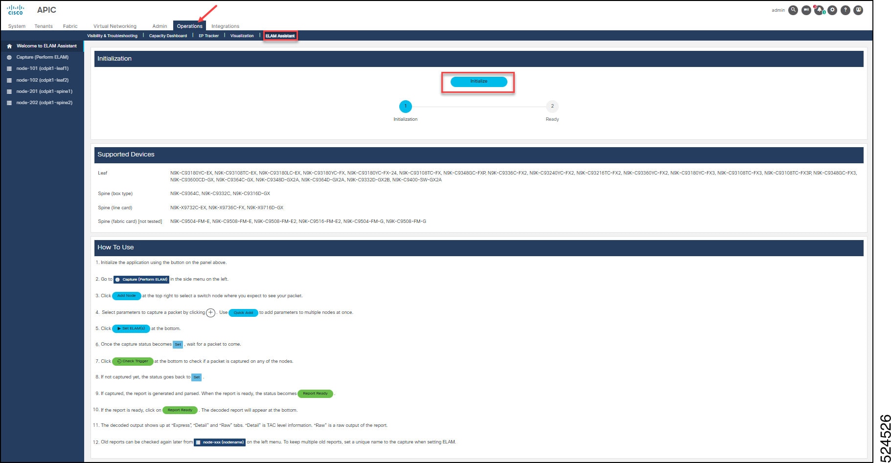
|
||||
|
Step 3 |
In the left banner, click Capture (Perform ELAM). The ELAM Parameters dialog box appears. |
||||
|
Step 4 |
On top-right of the ELAM Parameters dialog box, click Add Node to display a drop-down list. Choose the node for non-modular switches or the slot for modular switches. Repeat as needed. This will add the node with 6 columns. 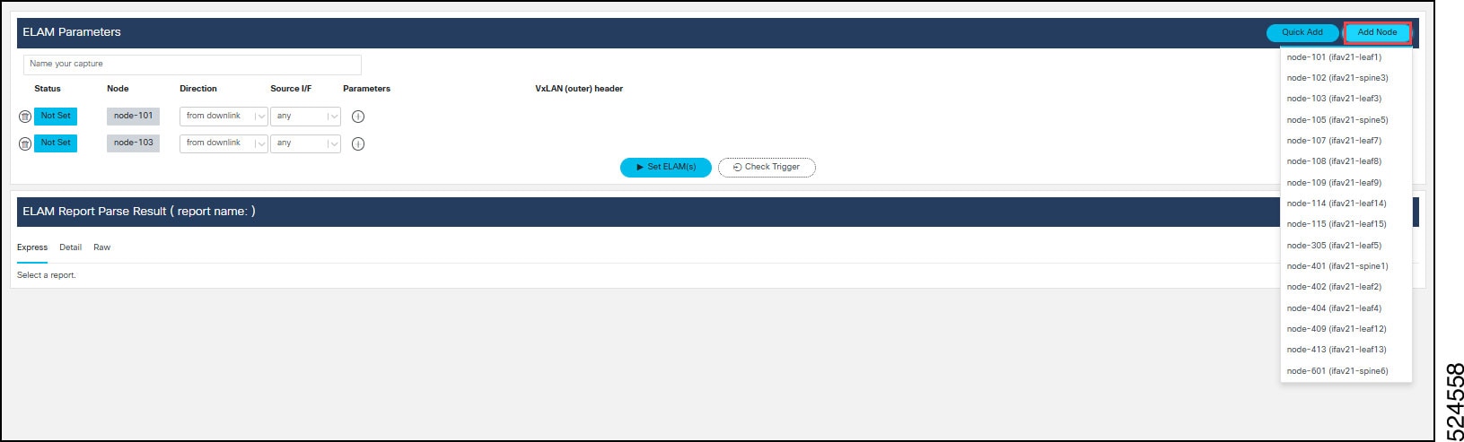
See details for Direction (in step 7), Source I/F (in step 8), Parameters (in step 9) and VxLAN (outer) header in step 10. |
||||
|
Step 5 |
(Optional) In the Name your capture text box, enter a unique name for your capture. Naming the capture enables you to look up the ELAM reports. |
||||
|
Step 6 |
From the Direction column, click the drop-down list to choose the direction of the captured packet. This enables you to specify from which direction the packet on the node is expected to come from—for a leaf switch. The options are:
|
||||
|
Step 7 |
From the Direction column, click the drop-down list to choose the direction of the spine switch: For spine switches, you can always specify VxLAN parameters in Step 10 below, regardless of the direction you select in this step because the packet going through a spine is always encapsulated in a VxLAN header. For a non-modular spine switch or a line card of a modular spine switch, there are two options:
For a fabric module of a modular spine, there is only one available option: from linecard. This means that the packet is coming from one of the line cards on the same spine switch. Just as the To LEAF/IPN option does for a line card, this option changes the Source I/F to an internal interface between a line card and a fabric module. |
||||
|
Step 8 |
From the Source I/F column, click the drop-down list and specify the source interface on which the packet is ingress for a node. This will be translated to hardware source identifier within the ASIC and applied as an ELAM trigger filter. The selection of source interface depends on the Direction you set. The default is any which can capture the packet from any of the interfaces that match the direction. |
||||
|
Step 9 |
For the Parameters column, set the parameters of the packet to be captured. Click the + icon to choose the specific parameter to set. You can choose multiple parameters. ELAM Assistant currently supports basic parameters in packet headers of L2, IPV4, L4 and ARP. For example, source MAC address and destination MAC address for L2 header, source IP address, destination IP address, IP protocol number, etc., for IPv4 header, ARP target IP, ARP sender IP ARP opcode etc., for ARP header. |
||||
|
Step 10 |
Specify the VxLAN (outer) header. From the VxLAN (outer) header column, you can specify the parameter of the VxLAN header along with the outer IPv4 and outer L2 header that encapsulate the packet with the parameter specified (if any) in the previous step. This option is available only for a certain set of directions for which VxLAN encapsulation is expected. When this option is available, click the + icon to choose the specific parameter to set. Use the drop-down menu. You can choose multiple parameters. ELAM Assistant currently supports basic VxLAN parameters such as VxLAN VNID, source and destination IPv4 address in the outer header, that is VTEP address. |
||||
|
Step 11 |
Alterntively, you can use Quick Add to specify the ELAM parameters. The Quick Add dialog appears. 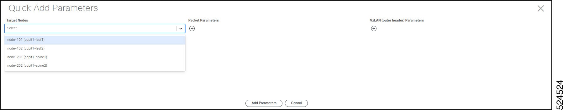
When using Quick Add, you can set all the ELAM Parameters for multiple switches. |
||||
|
Step 12 |
Once you select all the switches and the parameters of the packet to be captured, click Set ELAM to set the ELAM capture on the switch(es).
|
||||
|
Step 13 |
Once the ELAM is set on all selected switches, wait for the packet to be sent and for the ELAM capture to be triggered. Then click Check Trigger to see whether the packet was captured. If the packet with the specified parameters was found and the ELAM capture was triggered on the switch, the status of the switch transitions to Generating Report, Parsing Report, then Report Ready. If the packet has yet to be captured, the status goes back to Set. Wait a few seconds more or until the packet is sent from the client, then click Check Triggeragain. If the packet has yet to be captured, it indicates that the packet with the specified parameters hasn't reached the switch. |
||||
|
Step 14 |
Click the Report Ready status of one of the switches to read the ELAM report, displayed at the bottom under ELAM Report Parse Result. 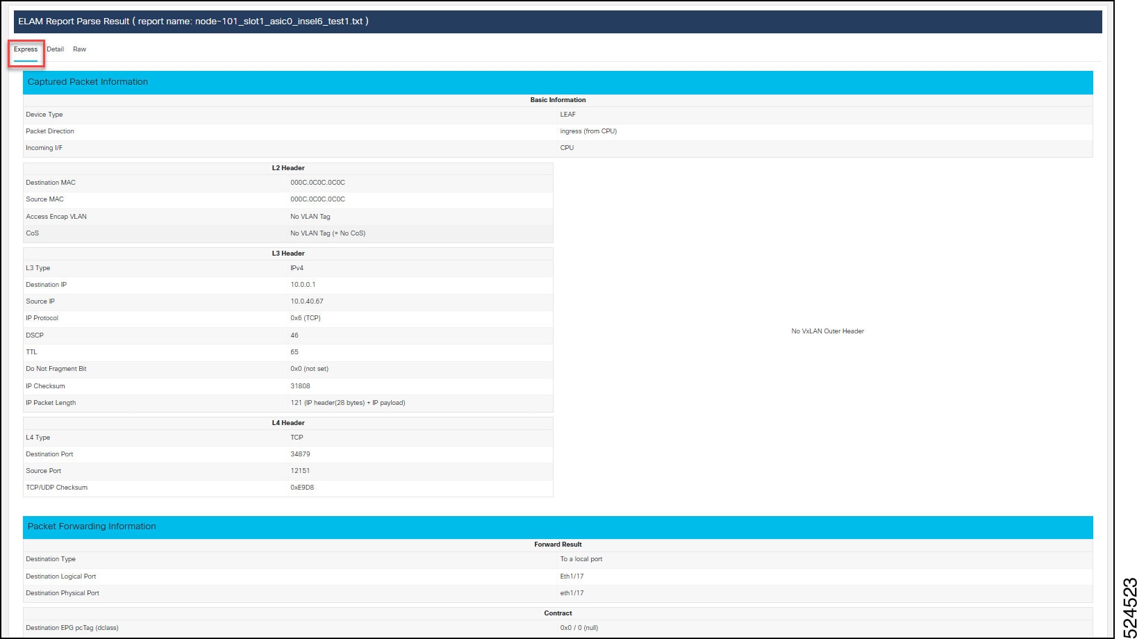
You will primarily use the Express tab content of the report. We have three tabs (Express, Details, and Raw). Express is the simplified report with which users without any ASIC-specific knowledge can understand what exactly happened to the packet. Details is for advanced users such as Cisco TAC who have detailed ASIC-level knowledge. Raw is the raw output of the report just in case some corner case field hasn't been captured in the Detailed view. |
||||
|
Step 15 |
To see the reports that were performed in the past, click
|
 Feedback