Basic User Tenant Configuration

This chapter contains the following sections:

Tenants

A tenant (fvTenant) is a logical container for application policies that enables administrators to implement domain-based access control.

  • Provides policy isolation.

  • Groups policies for customers, organizations, or administrative domains.

  • Supports IPv4, IPv6, and dual-stack network configurations.

Tenant components and configuration

A tenant contains filters, contracts, external networks, bridge domains, VRFs, and application profiles with endpoint groups (EPGs). Objects in a tenant inherit the policies of that tenant.

The following configuration guidelines apply to tenants:

  • Tenants can be isolated from one another or configured to share resources.

  • You must configure a tenant before deploying any Layer 4 through Layer 7 services.

  • You can associate each VRF with multiple bridge domains.


Note


In the APIC GUI tenant navigation hierarchy, a VRF, also called a context, is labeled as a private network.


The following figure shows the tenant portion of the management information tree (MIT).
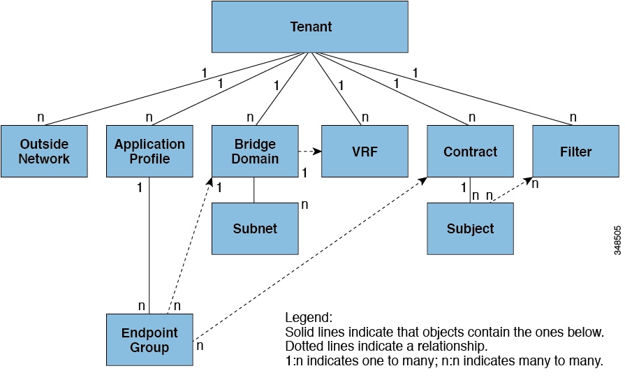
Figure 1. Tenant management information tree

Routing within a tenant

The Cisco ACI fabric provides distributed default gateway functionality and routes traffic between fabric Virtual Extensible LAN (VXLAN) networks.

  • When you configure a subnet in the APIC, the fabric provides a virtual default gateway, also called a switched virtual interface (SVI).

  • The virtual default gateway is available on every switch that has an endpoint connected to the tenant subnet.

  • For a given tenant subnet, ingress interfaces throughout the fabric use the same router IP address and MAC address.

Layer 3 VNIDs Facilitate Transporting Inter-subnet Tenant Traffic

Layer 3 VNIDs are identifiers assigned to each tenant VRF in the Cisco ACI fabric that enable routing and transport of inter-subnet tenant traffic across the fabric.

  • Each tenant receives a single L3 VNID, which is used to route traffic between subnets within the tenant.

  • The ACI fabric provides a distributed virtual default gateway, sharing the same IP and MAC address across all ingress interfaces for a tenant subnet.

  • VXLAN encapsulation and VTEP devices decouple endpoint identity from location, allowing efficient forwarding and routing without spanning-tree protocol.

How Layer 3 VNIDs Enable Inter-subnet Routing in Cisco ACI

The Cisco ACI fabric provides tenant default gateway functionality that routes between VXLAN networks. For each tenant, the fabric provides a virtual default gateway that spans all of the leaf switches assigned to the tenant. This gateway operates at the ingress interface of the first leaf switch connected to the endpoint, and all ingress interfaces share the same router IP and MAC address for a given tenant subnet.

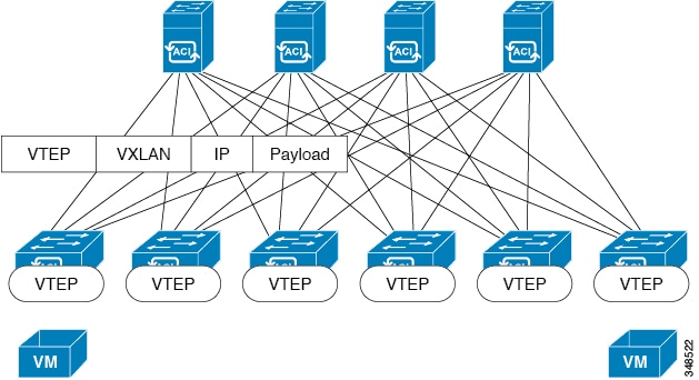
The Cisco ACI fabric decouples the tenant endpoint address (its identifier) from the location of the endpoint, which is defined by its VXLAN tunnel endpoint (VTEP) address. Forwarding within the fabric is performed between VTEPs.

  • Each VTEP has a switch interface on the local LAN segment for local endpoint communication through bridging.

  • Each VTEP has an IP interface to the transport IP network, with a unique IP address identifying the VTEP device on the infrastructure VLAN.

The VTEP device uses its IP interface to encapsulate Ethernet frames and transmit them to the transport network. It also discovers remote VTEPs and learns remote MAC Address-to-VTEP mappings through its IP interface.

The VTEP in Cisco ACI maps the internal tenant MAC or IP address to a location using a distributed mapping database. After a lookup, the VTEP sends the original data packet encapsulated in VXLAN to the destination VTEP. The destination leaf switch de-encapsulates the packet and delivers it to the receiving host. This model enables a full mesh, single hop, loop-free topology without the need for spanning-tree protocol.

The VXLAN segments are independent of the underlying network topology, and the underlying IP network between VTEPs is independent of the VXLAN overlay. Routing is based on the outer IP address header, with the initiating VTEP as the source and the terminating VTEP as the destination.

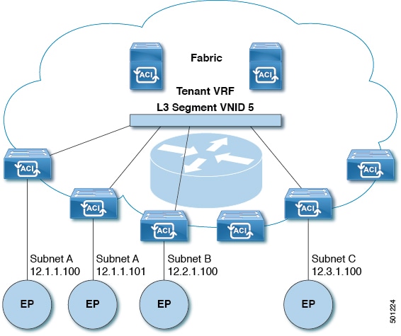
For each tenant VRF, Cisco ACI assigns a single L3 VNID. Traffic is transported across the fabric according to the L3 VNID, and at the egress leaf switch, ACI routes the packet from the L3 VNID to the VNID of the egress subnet.

Traffic arriving at the fabric ingress and sent to the Cisco ACI default gateway is routed into the Layer 3 VNID, providing efficient forwarding for intra-tenant routed traffic. For example, traffic between two VMs in the same tenant but on different subnets only needs to reach the ingress switch interface before being routed to the correct destination.

To distribute external routes within the fabric, Cisco ACI route reflectors use multiprotocol BGP (MP-BGP). The fabric administrator provides the autonomous system (AS) number and specifies the spine switches that become route reflectors.


Note


Cisco ACI does not support IP fragmentation. Therefore, when you configure Layer 3 Outside (L3Out) connections to external routers, or Multi-Pod connections through an Inter-Pod Network (IPN), it is recommended that the interface MTU is set appropriately on both ends of a link.

IGP Protocol Packets (EIGRP, OSPFv3) are constructed by components based on the Interface MTU size. In Cisco ACI , if the CPU MTU size is less than the Interface MTU size and if the constructed packet size is greater than the CPU MTU, then the packet is dropped by the kernel, especially in IPv6. To avoid such control packet drops always configure the same MTU values on both the control plane and on the interface.

On some platforms, such as Cisco ACI , Cisco NX-OS, and Cisco IOS, the configurable MTU value does not take into account the Ethernet headers (matching IP MTU, and excluding the 14-18 Ethernet header size), while other platforms, such as IOS-XR, include the Ethernet header in the configured MTU value. A configured value of 9000 results in a max IP packet size of 9000 bytes in Cisco ACI , Cisco NX-OS, and Cisco IOS, but results in a max IP packet size of 8986 bytes for an IOS-XR untagged interface.

For the appropriate MTU values for each platform, see the relevant configuration guides.

We highly recommend that you test the MTU using CLI-based commands. For example, on the Cisco NX-OS CLI, use a command such as ping 1.1.1.1 df-bit packet-size 9000 source-interface ethernet 1/1.


Figure 2. ACI Decouples Identity and Location
Figure 3. Layer 3 VNIDs Transport ACI Inter-subnet Tenant Traffic

Router peering and route distribution

Summary

Router peering and route distribution involve the following components:

  • Leaf switches establish routing protocol peering sessions with external routers and maintain forwarding tables containing the learned routes.

  • External routers establish routing protocol peering sessions and advertise WAN routes.

  • Spine switches act as route reflectors and distribute external routes throughout the fabric.

  • Tenant endpoints send packets to the default gateway in the Cisco ACI fabric.

Workflow

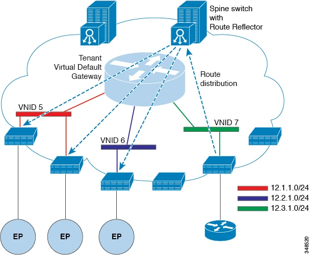
Figure 4. Router peering
Leaf switches peer with external routers, and spine switches distribute the learned external routes throughout the fabric.

Router peering and route distribution occur as follows:

  1. The leaf switch interface is configured to establish a routing protocol peering session with the external router.
  2. The leaf switch sends the routes learned through the peering session to the spine switches.
  3. The spine switches act as route reflectors and distribute the external routes to all leaf switches that have interfaces belonging to the same tenant. The leaf switches install the routes as longest prefix match (LPM) entries in their forwarding tables. Each entry identifies the virtual tunnel endpoint (VTEP) IP address of the remote leaf switch to which the external router is connected.
  4. WAN routes do not use a forwarding proxy. If the WAN routes exceed the capacity of a leaf switch forwarding table, the leaf switch drops the traffic.
  5. Because the external router is not the default gateway, tenant endpoints send their packets to the default gateway in the Cisco ACI fabric.

Bridged interface to an external router

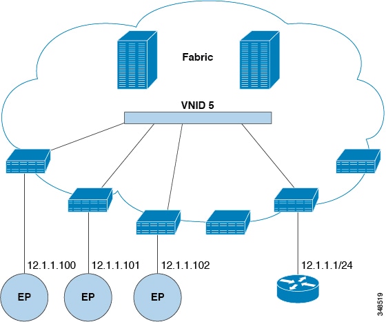
With a bridged interface, an external router provides the default gateway for the tenant virtual network identifier (VNID).

The Cisco ACI fabric does not maintain routing information about the external router. The APIC statically assigns the leaf switch interface to its endpoint group (EPG).

Bridged interface topology

Figure 5. Bridged external router

Route reflectors

An ACI fabric route reflector is a spine switch that

  • uses MP-BGP to distribute external routes throughout the fabric

  • requires you to select spine switches for the route reflector role

  • requires an autonomous system number, and

  • provides redundancy when you configure at least two spine switches as route reflectors in each pod.

External connectivity and route distribution

After you enable route reflectors, configure L3Outs on leaf switches to connect the fabric to external networks. Leaf switches that provide this connectivity are called border leaf switches.

Each border leaf switch exchanges routes with external devices through dynamic routing protocols or static routes. The spine route reflectors then distribute these routes to all leaf switches in the fabric.


Note


For the maximum number of routes supported on each leaf switch, refer to the Verified Scalability Guide for Cisco APIC for your release.


External connectivity through a Layer 3 Outside

A Layer 3 Outside (L3Out) is a tenant configuration object that provides connectivity between the Cisco ACI fabric and an external routed network.

  • Supports routing protocols such as Open Shortest Path First (OSPF).

  • Uses multiprotocol Border Gateway Protocol (MP-BGP) route reflectors to distribute external routes within the fabric.

  • Operates within a specific tenant, such as the mgmt tenant.

External connectivity configuration requirements

Configuring external connectivity requires the following components:

  1. Define the L3Out in the target tenant.

  2. Configure a routing protocol, such as OSPF, to exchange routes with the external network.

  3. Configure MP-BGP route reflectors to distribute the external routes within the fabric.

Configure an MP-BGP route reflector using the GUI

Procedure

Step 1

From the menu bar, choose System > System Settings.

Step 2

In the Navigation pane, right-click BGP Route Reflector, and choose Create Route Reflector Node.

Step 3

In the Create Route Reflector Node dialog box, choose the spine switch that you want to configure from the Spine Node drop-down list, and click Submit.

Note


Repeat the node-creation process for each additional spine switch.

The APIC designates the spine switch as a route reflector.

Step 4

In the BGP Route Reflector properties area, enter the autonomous system number in the Autonomous System Number field, and click Submit.

Note


If the external router uses BGP, the autonomous system number must match the autonomous system number configured on the router connected to the leaf switch. If the fabric learns routes through static routing or OSPF, you can enter any valid autonomous system number.

Step 5

From the menu bar, choose Fabric > Fabric Policies > Pods > Policy Groups.

Step 6

In the Navigation pane, right-click Policy Groups, and choose Create Pod Policy Group.

Step 7

In the Create Pod Policy Group dialog box, enter a name for the pod policy group in the Name field.

Step 8

From the BGP Route Reflector Policy drop-down list, choose the BGP route reflector policy, and click Submit.

The APIC associates the BGP route reflector policy with the pod policy group and enables the BGP process on the leaf switches.

Step 9

From the menu bar, choose Fabric > Fabric Policies > Profiles > Pod Profile default > default.

Step 10

In the Work pane, choose the pod policy group that you created from the Fabric Policy Group drop-down list, and click Submit.

The APIC applies the pod policy group to the fabric policy group.


MP-BGP route reflectors for the Cisco ACI fabric

A multiprotocol Border Gateway Protocol (MP-BGP) route reflector simplifies internal BGP scaling by enabling a spine switch to distribute routes among leaf switches in the Cisco ACI fabric.

  • Requires an active MP-BGP process.

  • Uses designated spine switches as route reflectors.

MP-BGP route reflector configuration example

Note


In this example, the BGP fabric autonomous system number (ASN) is 100, and spine switches 104 and 105 are the MP-BGP route reflectors.


The following commands configure the BGP fabric ASN and designate the route reflectors:

apic1(config)# bgp-fabric
				apic1(config-bgp-fabric)# asn 100
				apic1(config-bgp-fabric)# route-reflector spine 104,105

Verify the MP-BGP route reflector configuration

Procedure

Step 1

Verify the MP-BGP process on each leaf switch.

  1. Use Secure Shell (SSH) to log in to each leaf switch as an administrator.

  2. Enter the show processes | grep bgp command and verify that the process state is S.

    A state of NR indicates that the process is not running and that the configuration was unsuccessful.

Step 2

Verify the autonomous system number on each spine switch.

  1. Use SSH to log in to each spine switch as an administrator.

  2. Enter these commands in the shell:

    Example:
    cd /mit/sys/bgp/inst
    								grep asn summary

The command displays the configured autonomous system number. A value of 0 indicates that the configuration was unsuccessful.


Create an OSPF L3Out for the management tenant by using the GUI

  • Verify that the router ID and logical interface profile IP address are different and do not overlap.

  • This procedure creates an OSPF L3Out for the management tenant. To create an OSPF L3Out for another tenant, select that tenant and create a VRF for it.

  • For more information, see Cisco APIC and Transit Routing.

Procedure

Step 1

On the menu bar, choose Tenants > mgmt.

Step 2

In the Navigation pane, expand Networking > L3Outs.

Step 3

Right-click L3Outs and choose Create L3Out.

The Create L3Out wizard appears.

Step 4

In the Identity window of the Create L3Out wizard, configure the L3Out.

  1. In the Name field, enter a name, such as RtdOut.

  2. From the VRF drop-down list, choose the in-band VRF, such as inb.

    Note


    This selection associates the L3Out with the in-band VRF.

  3. From the L3 Domain drop-down list, choose the appropriate domain.

  4. Check the OSPF check box.

  5. In the OSPF Area ID field, enter the area ID.

  6. For OSPF Area Control, check the appropriate check boxes.

  7. For OSPF Area Type, choose the appropriate area type.

  8. For OSPF Area Cost, enter the appropriate value.

  9. Click Next.

    The Nodes and Interfaces window appears.

Step 5

In the Nodes and Interfaces window, configure the nodes and interfaces.

  1. Uncheck the Use Defaults check box.

    You can now edit the Node Profile Name field.

  2. In the Node Profile Name field, enter a name, such as borderLeaf.

  3. From the Node ID drop-down list, choose the first node, such as leaf1.

  4. In the Router ID field, enter a unique router ID.

  5. In the Loopback Address field, retain the router ID, enter a different IP address, or clear the field if you do not want to use a loopback address.

    Note


    The Loopback Address field is automatically populated with the value from the Router ID field. This behavior is equivalent to the Use Router ID for Loopback Address option in previous releases.

  6. As required, configure the Interface, IP Address, Interface Profile Name, and MTU fields for the first node.

  7. In the Nodes area, click the + icon to add another node.

  8. From the Node ID drop-down list, choose the second node, such as leaf2.

  9. In the Router ID field, enter a unique router ID for the second node.

  10. In the Loopback Address field, retain the router ID, enter a different IP address, or clear the field if you do not want to use a loopback address.

    Note


    The Loopback Address field is automatically populated with the value from the Router ID field. This behavior is equivalent to the Use Router ID for Loopback Address option in previous releases.

  11. As required, configure the Interface, IP Address, Interface Profile Name, and MTU fields for the second node.

  12. Click Next.

    The Protocols window appears.

Step 6

In the Protocols window, choose default in the Policy area, and then click Next.

The External EPG window appears.

Step 7

In the External EPG window, configure the external EPG.

  1. In the Name field, enter a name for the external network, such as extMgmt.

  2. Uncheck the Default EPG for all external networks check box.

    The Subnets area appears.

  3. Click the + icon.

    The Create Subnet dialog appears.

  4. In the IP address field, enter the subnet IP address and prefix length.

  5. For Scope, check the appropriate check boxes, and then click OK.

  6. In the External EPG window, click Finish.

    The L3Out, such as RtdOut, appears in the L3Outs area of the Work pane.


Create an OSPF external routed network for a tenant by using the NX-OS-style CLI

Configuring external routed connectivity requires the following tasks:

  • Create a VRF in the tenant.

  • Configure Layer 3 connectivity for the VRF on the border leaf switches that connect to the external routed network. This configuration can include interfaces, routing protocols such as BGP, OSPF, or EIGRP, protocol parameters, and route maps.

  • Create external Layer 3 EPGs in the tenant and deploy them on the border leaf switches. External routed subnets in a VRF that share the same policy within the Cisco ACI fabric form one external Layer 3 EPG, also called a prefix EPG.

Complete the configuration in the following modes:

  • Tenant configuration mode: Create the VRF and configure the external Layer 3 EPG.

  • Leaf configuration mode: Configure Layer 3 connectivity and deploy the external Layer 3 EPG.

Before you create an OSPF external routed network, select a tenant and create a VRF in that tenant.


Note


The examples provide external routed connectivity to the web EPG in the OnlineStore application profile for the exampleCorp tenant.


Procedure

Step 1

Configure the VLAN domain.

Example:
apic1(config)# vlan-domain dom_exampleCorp
						apic1(config-vlan)# vlan 5-1000
						apic1(config-vlan)# exit

Step 2

Create the tenant VRF and enable policy enforcement.

Example:
apic1(config)# tenant exampleCorp
						apic1(config-tenant)# vrf context exampleCorp_v1
						apic1(config-tenant-vrf)# contract enforce
						apic1(config-tenant-vrf)# exit

Step 3

Create the tenant bridge domain and configure its gateway address for public advertisement.

The scope public option allows the routing protocol to advertise the gateway address to the external Layer 3 network.

Example:
apic1(config-tenant)# bridge-domain exampleCorp_b1
						apic1(config-tenant-bd)# vrf member exampleCorp_v1
						apic1(config-tenant-bd)# exit
						apic1(config-tenant)# interface bridge-domain exampleCorp_b1
						apic1(config-tenant-interface)# ip address 172.1.1.1/24 scope public
						apic1(config-tenant-interface)# exit

Step 4

Configure the tenant VRF on the border leaf switch.

Example:
apic1(config)# leaf 101
						apic1(config-leaf)# vrf context tenant exampleCorp vrf exampleCorp_v1

Step 5

Configure the OSPF area and outbound route map.

Example:
apic1(config-leaf)# router ospf default
						apic1(config-leaf-ospf)# vrf member tenant exampleCorp vrf exampleCorp_v1
						apic1(config-leaf-ospf-vrf)# area 0.0.0.1 route-map map100 out
						apic1(config-leaf-ospf-vrf)# exit
						apic1(config-leaf-ospf)# exit

Step 6

Assign the VRF to the subinterface and enable OSPF for the area.

Note


Before you configure the subinterface, use the no switchport command to convert the main interface, Ethernet 1/11 in this example, to a Layer 3 interface. Assign the main interface to the dom_exampleCorp VLAN domain, which contains the encapsulation VLAN used by the subinterface. In the interface name ethernet 1/11.500, 500 is the encapsulation VLAN.

Example:
apic1(config-leaf)# interface ethernet 1/11
						apic1(config-leaf-if)# no switchport
						apic1(config-leaf-if)# vlan-domain member dom_exampleCorp
						apic1(config-leaf-if)# exit
						apic1(config-leaf)# interface ethernet 1/11.500
						apic1(config-leaf-if)# vrf member tenant exampleCorp vrf exampleCorp_v1
						apic1(config-leaf-if)# ip address 157.10.1.1/24
						apic1(config-leaf-if)# ip router ospf default area 0.0.0.1

Step 7

Configure the external Layer 3 EPG policy.

The policy identifies the external subnet and consumes the contract that provides connectivity to the web EPG.

Example:
apic1(config)# tenant exampleCorp
						apic1(config-tenant)# external-l3 epg l3epg100
						apic1(config-tenant-l3ext-epg)# vrf member exampleCorp_v1
						apic1(config-tenant-l3ext-epg)# match ip 145.10.1.0/24
						apic1(config-tenant-l3ext-epg)# contract consumer web
						apic1(config-tenant-l3ext-epg)# exit
						apic1(config-tenant)# exit

Step 8

Deploy the external Layer 3 EPG on the border leaf switch.

Example:
apic1(config)# leaf 101
						apic1(config-leaf)# vrf context tenant exampleCorp vrf exampleCorp_v1
						apic1(config-leaf-vrf)# external-l3 epg l3epg100

Creating Tenants, VRFs, and Bridge Domains

Tenants

A tenant is a logical container that isolates network resources, traffic, configurations, and policies within the fabric.

  • Defines an administrative boundary for network resources.

  • Supports multitenancy by separating traffic and configurations.

  • Enables independent policy management for different user groups.

Tenant configuration

A tenant is a logical container that organizes network elements and application policies. After you create a tenant, you can configure the following objects within it:

  • Filters

  • Contracts

  • Bridge domains

  • Application profiles

VRFs and bridge domains

A VRF provides the Layer 3 context for the bridge domains associated with it. This relationship enables the subnets in a bridge domain to participate in tenant-specific routing and network segmentation.

  • The VRF provides tenant-specific Layer 3 isolation.

  • The bridge domain associates its subnets with the VRF routing context.

IPv6 Neighbor Discovery

For information about enabling IPv6 Neighbor Discovery, see IPv6 and Neighbor Discovery in the Cisco APIC Layer 3 Networking Configuration Guide.

Create a tenant, VRF, and bridge domain using the GUI

This task enables you to create the foundational network components required for ACI fabric configuration.

If you have a public subnet when you configure the routed outside, you must associate the bridge domain with the outside configuration.

Follow these steps to create a tenant, VRF, and bridge domain using the GUI:

Procedure


Step 1

On the menu bar, choose Tenants > Add Tenant.

Step 2

In the Create Tenant dialog box, perform the following tasks:

  1. In the Name field, enter a name.

  2. In the Security Domains section, click the + to open the Create Security Domain dialog box.

  3. In the Name field, enter a name for the security domain, then click Submit.

  4. In the Create Tenant dialog box, click Update for the security domain that you created.

  5. Fill in the other fields as necessary.

  6. Click Submit.

    The tenant_name > Networking screen displays.

Step 3

In the Work pane, drag the VRF icon to the canvas to open the Create VRF dialog box, and perform the following tasks:

  1. In the Name field, enter a name.

  2. Fill in the other fields as necessary.

  3. Click Submit to complete the VRF instance configuration.

Step 4

In the Work pane, drag the Brdige Domain icon to the canvas within the circle around the VRF instance to connect the two. In the Create Bridge Domain dialog box that displays, perform the following tasks:

  1. In the Name field, enter a name.

  2. Fill in the other fields as necessary.

  3. Click Next.

  4. In the Subnets section, click the + to open the Create Subnet dialog box.

  5. In the Gateway IP field, enter the IP address and subnet mask.

  6. Fill in the other fields as necessary.

  7. Click OK.

  8. Back in the Create Bridge Domain dialog box, fill in the other fields as necessary.

  9. Click Next.

  10. Fill in the fields as necessary.

  11. Click OK to complete bridge domain configuration.

Step 5

In the Work pane, drag the L3 icon to the canvas within the circle around the VRF instance to connect the two. In the Create Routed Outside dialog box that displays, perform the following tasks:

  1. In the Name field, enter a name.

  2. In the Nodes field, click the + button.

  3. In the Create Node Profile dialog box, fill in the other fields as necessary.

  4. Click OK.

  5. Put a check in the BGP, OSPF, or EIGRP check boxes if desired.

  6. Fill in the other fields and Create static route as necessary.

  7. Click Next.

  8. Fill in the fields as necessary.

  9. Click OK to complete the Layer 3 configuration.

To confirm the Layer 3 configuration, in the Navigation pane, expand Networking > VRFs.

Deploying EPGs

Static EPG deployment on a specific port

Static deployment of an endpoint group (EPG) associates the EPG directly with a physical interface on a leaf switch.

Static EPG deployment

In a typical deployment, use the Cisco APIC to create a static path binding between an EPG and a specific leaf switch port.

Deploy an EPG on a specific node or port using the GUI

You can create an EPG on a specific node or a specific port on a node to have precise control over EPG deployment locations.

Before you begin

The tenant where you deploy the EPG is already created.

Follow these steps to deploy an EPG on a specific node or port using the GUI:

Procedure


Step 1

Log in to the Cisco APIC.

Step 2

Choose Tenants > tenant.

Step 3

In the left navigation pane, expand tenant, Application Profiles, and the application profile.

Step 4

Right-click Application EPGs and choose Create Application EPG.

Step 5

In the Create Application EPG STEP 1 > Identity dialog box, complete the following steps:

  1. In the Name field, enter a name for the EPG.

  2. From the Bridge Domain drop-down list, choose a bridge domain.

  3. Check the Statically Link with Leaves/Paths check box.

    This check box allows you to specify on which port you want to deploy the EPG.

  4. Click Next.

  5. From the Path drop-down list, choose the static path to the destination EPG.

Step 6

In the Create Application EPG STEP 2 > Leaves/Paths dialog box, from the Physical Domain drop-down list, choose a physical domain.

Step 7

Complete one of the following sets of steps:

Option Description
If you want to deploy the EPG on... Then
A node
  1. Expand the Leaves area.

  2. From the Node drop-down list, choose a node.

  3. In the Encap field, enter the appropriate VLAN.

  4. (Optional) From the Deployment Immediacy drop-down list, accept the default On Demand or choose Immediate.

  5. (Optional) From the Mode drop-down list, accept the default Trunk or choose another mode.

A port on the node
  1. Expand the Paths area.

  2. From the Path drop-down list, choose the appropriate node and port.

  3. (Optional) In the Deployment Immediacy field drop-down list, accept the default On Demand or choose Immediate.

  4. (Optional) From the Mode drop-down list, accept the default Trunk or choose another mode.

  5. In the Port Encap field, enter the secondary VLAN to be deployed.

  6. (Optional) In the Primary Encap field, enter the primary VLAN to be deployed.

Step 8

Click Update and click Finish.

Step 9

In the left navigation pane, expand the EPG that you created.

Step 10

Complete one of the following actions:

  • If you created the EPG on a node, click Static Leafs, and in the work pane view details of the static binding paths.
  • If you created the EPG on a port of the node, click Static Ports, and in the work pane view details of the static binding paths.

Domains, attachable access entity profiles, and VLAN for EPG deployment

Domains, Attachable Access Entity Profiles, and VLANs for EPG deployment are network configuration components that

  • provide the mandatory infrastructure elements required to deploy an endpoint group (EPG) on a specific port

  • establish the association between EPGs and domains to validate ports and VLANs usage, and

  • ensure proper configuration validation through APIC checks for EPG-domain associations.

EPG domain types and validation requirements

All endpoint groups (EPGs) require a domain. Interface policy groups must also be associated with Attachable Access Entity Profile (AEP), and the AEP must be associated with a domain, if the AEP and EPG have to be in same domain. Based on the association of EPGs to domains and of interface policy groups to domains, the ports and VLANs that the EPG uses are validated.

The following domain types associate with EPGs:

  • Application EPGs

  • Layer 3 external outside network instance EPGs

  • Layer 2 external outside network instance EPGs

  • Management EPGs for out-of-band and in-band access

The APIC checks if an EPG is associated with one or more of these types of domains. If the EPG is not associated, the system accepts the configuration but raises a fault. The deployed configuration may not function properly if the domain association is not valid. For example, if the VLAN encapsulation is not valid for use with the EPG, the deployed configuration may not function properly.


Note


EPG association with the AEP without static binding does not work in a scenario when you configure the EPG as Trunk under the AEP with one end point under the same EPG supporting Tagging and the other end point in the same EPG does not support VLAN tagging. While associating AEP under the EPG, you can configure it as Trunk, Access (Tagged) or Access (Untagged).


Create domains and VLANS to deploy an EPG on a specific port using the GUI

Before you begin

  • The tenant where you deploy the EPG is already created.

  • An EPG is statically deployed on a specific port.

Procedure


Step 1

On the menu bar, choose Fabric > Access Policies.

Step 2

In the Navigation pane, choose Quick Start.

Step 3

In the Work pane, click Configure Interfaces.

Step 4

In the Configure Interfaces dialog, perform these actions:

  1. For Node Type, click Leaf.

  2. For Port Type, click Access.

  3. For Interface Type, choose the desired type.

  4. For Interface Aggregation Type, choose Individual.

  5. For Node, click Select Node, put a check in the box for the desired node, then click OK. You can select multiple nodes.

  6. For Interfaces For All Switches, enter the range of desired interfaces.

  7. For Leaf Access Port Policy Group, click Select Leaf Access Port Policy Group.

  8. In the Select Leaf Access Port Policy Group dialog, click Create Leaf Access Port Policy Group.

  9. In the Create Leaf Access Port Policy Group dialog, for Link Level Policy, click Select Link Level Policy.

  10. Choose a link level policy and click Select, or click Create Link Level Policy, fill out the fields as desired, and click Save.

Step 5

Create a domain and VLAN pool by performing the following actions:

  1. In the Navigation pane, expand Physical and External Domains.

  2. Right-click Physical Domains and choose the appropriate Create Physical Domain.

  3. For Name, enter a name for the domain.

  4. For VLAN Pool, choose Create VLAN Pool, fill out the fields as desired, then click Submit.

  5. Fill out the remaining fields as desired.

  6. Click Submit.

Step 6

On the menu bar, choose Tenants > All Tenants.

Step 7

In the Work pane, double click the desired tenant.

Step 8

In the Navigation pane, expand Tenant_name > Application Profiles > profile_name > Application EPGs > EPG_name.

Step 9

Right-click Static Ports and choose Deploy to Port.

  1. In the Deploy EPG to Port dialog, from the Pod drop-down list, choose the desired pod.

  2. From the Leaf drop-down list, choose the desired leaf.

  3. From the Port drop-down list, choose the desired port.

  4. From the VLAN drop-down list, choose the desired VLAN.

  5. Fill out the remaining fields as desired.

  6. Click Submit.

    The EPG is deployed on the specified port.

Step 10

In the Navigation pane, expand Fabric > Access Policies > Global Policies > Attachable Access Entity Profiles.

  1. Right-click Attachable Access Entity Profiles and choose Create Attachable Access Entity Profile.

  2. In the Create Attachable Access Entity Profile dialog, enter a name in the Name field.

  3. In the Domains area, click the + icon.

  4. In the Add Physical Domain Association dialog, from the Physical Domain Profile drop-down list, choose the domain that you created.

  5. Click Submit.

    The AEP is associated with a specific port on a node and with a domain. The physical domain is associated with the VLAN pool and the tenant is associated with this physical domain.

The switch profile and the interface profile are created. The policy group is created in the port block under the interface profile. The AEP is automatically created, and it is associated with the port block and with the domain. The domain is associated with the VLAN pool and the tenant is associated with the domain.


Deploy an application EPG through an AEP to multiple ports

Deploying an application EPG through an AEP to multiple ports is a configuration method where you

  • associate attachable entity profiles directly with application EPGs through the APIC GUI and REST API

  • deploy the associated application EPGs to all ports associated with the attachable entity profile, and

  • accomplish this deployment in a single configuration.

Deploy an EPG through an AEP to multiple interfaces using the APIC GUI

You can associate an application EPG with the attachable access entity profile to deploy an EPG over all the ports associated with this attachable access entity profile.

Prior to Cisco APIC 6.1(3), you could associate an application with an attachable access entity profile only through the access policies hierarchy. Starting from Cisco APIC 6.1(3), you can now associate an application with an attachable access entity profile either through the tenant hierarchy or through the access policies hierarchy.


Note


When you create an AEP attachment through either of these specific hierarchies you must also perform any subsequent modification operation only in the hierarchy that it was created in. If there is an overlap in operations, Cisco APIC will reject this configuration.


Before you begin

  • The target application EPG is created.

  • The VLAN pools has been created containing the range of VLANs you wish to use for EPG Deployment on the AEP.

  • The physical domain has been created and linked to the VLAN Pool and AEP.

  • The target attachable access entity profile is created and is associated with the ports on which you want to deploy the application EPG.

Follow these steps to deploy an EPG through an AEP to multiple interfaces using the APIC GUI:

Procedure


Step 1

You can use either of the following methods to associate an application EPG with an attachable access entity profile:

  1. Open the page for the Application EPG to use. In the GUI, click Tenant > tenant_name > Application Profiles > epg_name > Static AAEP.

  2. In the Static AAEP window, associate the target attachable access entity profile with the application EPG.

Field Action
Name

Select a name for the AEP.

Encap

Enter the VLAN ID over which the target application EPG will communicate.

Primary Encap

(Optional) If the application EPG requires a primary VLAN, enter the primary VLAN ID.

Deployment Immediacy

In the Deployment Immediacy field, accept the default On Demand or choose Immediate.

Mode

To specify the mode in which data is transmitted:

  • Trunk -- Select if traffic from the host is tagged with a VLAN ID.

  • Trunk (Native) -- Select if traffic from the host is tagged with an 802.1p tag.

  • Access (Untagged) -- Select if the traffic from the host is untagged.

Step 2

Alternatively, use this method to associate an application EPG with an attached entity profile.

  1. Open the page for the attachable access entity profile to use. In the GUI, click Fabric > Access Policies > Policies > Global > Attachable Access Entity Profiles.

  2. Click the target attachable access entity profile to open its Attachable Access Entity Profile window.

  3. Click the Show Usage button to view the leaf switches and interfaces associated with this attachable access entity profile.

    The application EPGs associated with this attachable access entity profile is deployed to all the ports on all the switches associated with this attachable access entity profile.

  4. Use the Application EPGs table to associate the target application EPG with this attachable access entity profile. Click + to add an application EPG entry. Each entry contains the following fields:

Field Action
Tenant

Use the drop-down to choose the tenant that contains the target application EPG.

Application Profile

Use the drop-down to choose the application profile that contains the target application EPG.

EPG

Use the drop-down to choose the target application EPG.

Encap

Enter the name of the VLAN (or range of VLANs, separated by commas) to which traffic from this application EPG is assigned.

Primary Encap

(Optional) If the application EPG requires a primary VLAN, enter the name of the primary VLAN ID.

Mode

Use the drop down to specify the mode in which data is transmitted:

  • Trunk -- Choose if traffic from the host is tagged with a VLAN ID.

  • Trun k(Native) -- Choose if traffic from the host is tagged with an 802.1p tag.

  • Access (Untagged) -- Choose if the traffic from the host is untagged.

Step 3

Click Submit.

The application EPGs associated with this attachable access entity profile is deployed to all the ports on all the switches associated with this attachable access entity profile.

Microsegmented EPGs

Microsegmentation with network-based attributes for bare-metal endpoints

Microsegmentation with network-based attributes uses attribute-based endpoint groups (EPGs) to isolate bare-metal endpoints according to their network identifiers.

  • MAC address filters isolate one or more servers.

  • IP address filters isolate individual addresses, subnets, or noncontiguous address ranges.

  • Physical endpoints can be isolated within one base EPG or across different base EPGs.

Network-based attribute types

You can implement microsegmentation by using the following network-based attributes:

  • An IP-based attribute isolates an individual IP address, a subnet, or multiple noncontiguous IP addresses to create a security zone similar to a firewall security zone.

  • A MAC-based attribute isolates one or more MAC addresses and can contain servers that are sending malicious traffic.

Configure network-based microsegmented EPGs for bare-metal endpoints by using the GUI

Use the Cisco APIC GUI to create a microsegmented EPG (uSeg EPG) that classifies physical endpoints by their IP or MAC addresses.

Procedure


Step 1

Log in to the Cisco APIC GUI.

Step 2

On the menu bar, choose Tenants, and then choose the tenant in which you want to create the uSeg EPG.

Step 3

In the Navigation pane, expand tenant-name > Application Profiles > application-profile-name > Application EPGs.

Step 4

Select a base EPG that contains endpoints for the new uSeg EPG.

  • To classify physical endpoints from the same base EPG, select that base EPG.
  • To classify physical endpoints from different base EPGs, select one of those base EPGs.

The properties of the base EPG appear in the Work pane.

Step 5

In the Work pane, click the Operational tab.

Step 6

Ensure that the Client End-Points tab is active.

The Work pane displays the physical endpoints that belong to the base EPG.

Step 7

Record the IP or MAC addresses of the endpoints that you want to add to the new uSeg EPG.

Step 8

(Optional) If the new uSeg EPG will contain endpoints from different base EPGs, repeat the preceding four steps for each additional base EPG.

Step 9

In the Navigation pane, right-click uSeg EPGs, and then choose Create uSeg EPG.

Step 10

In the Create uSeg EPG dialog, configure the uSeg EPG.

  1. In the Name field, enter a name.

    Use a name that identifies the EPG as a microsegment.

  2. For Intra-EPG Isolation, choose enforced or unenforced.

    If you choose enforced, ACI prevents communication between endpoints in the uSeg EPG.

  3. From the Bridge Domain drop-down list, choose a bridge domain.

  4. In the uSeg Attributes area, choose IP Address Filter or MAC Address Filter from the + drop-down list.

Step 11

Configure the selected address filter.

If you selected...

Then...

IP Address Filter

  1. In the Create IP Attribute dialog, enter a name in the Name field.

    Use a name that identifies the function of the filter.

  2. In the IP Address field, enter an IP address or a subnet with the appropriate subnet mask.

  3. Click OK.

  4. To include noncontiguous IP addresses in the uSeg EPG, create additional IP address filters as needed.

  5. In the Create uSeg EPG dialog, click Submit.

MAC Address Filter

  1. In the Create MAC Attribute dialog, enter a name in the Name field.

    Use a name that identifies the function of the filter.

  2. In the MAC Address field, enter a MAC address.

  3. Click OK.

  4. In the Create uSeg EPG dialog, click Submit.

Step 12

Associate the uSeg EPG with a physical domain.

  1. In the Navigation pane, expand uSeg EPGs, and then expand the uSeg EPG that you created.

  2. Click Domains (VMs and Bare-Metals).

  3. In the Work pane, choose Actions > Add Physical Domain Association.

  4. In the Add Physical Domain Association dialog, choose a profile from the Physical Domain Profile drop-down list.

  5. For Deploy Immediacy, retain the default value, On Demand.

  6. For Resolution Immediacy, retain the default value, Immediate.

  7. Click Submit.

Step 13

Associate the uSeg EPG with the appropriate leaf switch.

  1. In the Navigation pane, expand the uSeg EPG, and then click Static Leafs.

  2. In the Static Leafs window, choose Actions > Statically Link with Node.

  3. In the Statically Link With Node dialog, select the leaf node and deployment mode.

  4. Click Submit.

Step 14

(Optional) Repeat the uSeg EPG creation and association steps for each additional network attribute-based EPG that you want to create.


What to do next

Verify that the attribute-based EPG was created correctly.

For an IP-based or MAC-based attribute, generate traffic from the endpoints in the new microsegment and verify that the endpoints are classified correctly.

IP address-based microsegmented EPG as a shared resource

An IP address-based microsegmented endpoint group (EPG) can operate as a shared resource across VRF boundaries.

  • The existing microsegmented EPG contains a subnet with a unicast IP address.

  • The subnet is advertised and shared with devices in VRFs other than its native VRF.

  • An IP attribute associates the EPG with the IP address of the shared subnet.

Shared microsegmented EPG configuration requirements

To use an IP address-based microsegmented EPG as a shared resource, meet the following requirements:

  1. Configure a subnet with a unicast IP address in an existing IP address-based microsegmented EPG.

  2. Enable the subnet for advertisement and sharing with devices in VRFs other than its native VRF.

  3. Configure an IP attribute with the appropriate option enabled to associate the EPG with the IP address of the shared subnet.

Configure an IP address-based microsegmented EPG as a shared resource by using the GUI

You can configure an IP address-based microsegmented EPG with a /32 subnet as a shared resource. The shared resource can be advertised outside the fabric and accessed from other VRFs.

Before you begin

Configure an IP address-based microsegmented EPG with a /32 subnet mask.


Note


Procedure


Step 1

Navigate to the IP address-based uSeg EPG.

  1. In the Cisco APIC GUI, choose Tenants > tenant_name > uSeg EPGs > uSeg_epg_name .

    The Properties pane for the uSeg EPG appears.

Step 2

Configure an IP attribute that matches the shared EPG subnet address.

  1. In the uSeg Attributes table, click +, and then choose IP Address Filter.

    The Create IP Attribute dialog appears.

  2. In the Name field, enter a name for the IP attribute.

  3. Check the Use FV Subnet check box.

    This option indicates that the IP attribute value matches the IP address of a shared subnet.

  4. Click Submit.

Step 3

Create a shared subnet for the uSeg EPG.

  1. In the Navigation pane, expand the IP address-based uSeg EPG, right-click Subnets, and choose Create EPG Subnets.

  2. In the Default Gateway field, enter the IP address of the microsegmented EPG with a /32 subnet mask.

    Note

     
    • The subnet mask must be /32.

    • For an IP address-based EPG, this value is the IP address of the shared EPG subnet, not a default gateway address.

  3. Check the Treat as a virtual IP address check box.

  4. Under Scope, check Advertised Externally and Shared between VRFs.

  5. Click Submit.


Remove shared-resource configuration from an IP address-based microsegmented EPG by using the GUI

Before you begin

Identify the following configuration before you remove the shared-resource configuration:

  • The subnet configured as the shared-resource address for the IP address-based microsegmented EPG.

  • The IP attribute for which Use FV Subnet is enabled.

To stop using an IP address-based microsegmented EPG as a shared resource, delete the shared subnet and configure its IP attribute to stop using that subnet.

Procedure


Step 1

Delete the shared subnet from the IP address-based microsegmented EPG.

  1. In the Cisco APIC GUI, choose Tenants > tenant_name > Application Profiles > application_profile_name > uSeg EPGs > uSeg_epg_name .

  2. In the Navigation pane, expand the IP address-based uSeg EPG, and then click Subnets.

  3. In the Subnets pane, select the subnet that is advertised externally and shared between VRFs, and then choose Actions > Delete.

  4. Click Yes to confirm the deletion.

Step 2

Disable Use FV Subnet for the associated IP attribute.

  1. In the Navigation pane, click the name of the IP address-based uSeg EPG.

    The Properties pane for the uSeg EPG appears.

  2. In the uSeg Attributes table, locate the IP attribute for which Use FV Subnet is enabled.

  3. Double-click the IP attribute.

    The Edit IP Attribute dialog appears.

  4. Uncheck the Use FV Subnet check box.

  5. In the IP Address field, enter another IP address attribute.

    Note


    The address must be a unicast address with a /32 subnet mask, such as 124.124.124.123/32.

  6. Click Submit.


Deploying Application Profiles and Contracts

Security policy enforcement

Security policy enforcement validates traffic against the policies defined between endpoint groups (EPGs) as packets traverse the leaf switches.

  • The ingress leaf switch marks each packet with its source EPG.

  • A forwarding lookup identifies the destination EPG and endpoint location.

  • The ingress or egress leaf switch enforces the policy, depending on where the destination EPG is identified.

Traffic forwarding and policy enforcement

A leaf switch performs a forwarding lookup for the destination IP address. The lookup can produce the following results:

  1. A unicast /32 match identifies the destination endpoint EPG and either the local interface or the virtual tunnel endpoint (VTEP) IP address of the remote leaf switch.

  2. A unicast subnet-prefix match identifies the destination subnet EPG and either the local interface or the VTEP IP address of the remote leaf switch.

  3. A multicast match identifies the local interfaces of local receivers, the outer destination IP address for Virtual Extensible LAN (VXLAN) encapsulation, and the EPG of the multicast group.

If the forwarding-table lookup does not find a match, the leaf switch sends the packet to the forwarding proxy on a spine switch. If the spine switch finds a match, it forwards the packet to the egress leaf switch. The egress leaf switch enforces the security policy by using the EPG information in the fabric header. If the spine switch does not find a match, it drops the packet.

The egress leaf switch learns and stores the source information. Because most traffic flows are bidirectional, the forwarding tables on both sides are populated, which enables ingress policy enforcement in both directions.


Note


Multicast and external router subnets always produce a match on the ingress leaf switch. The ingress leaf switch enforces the security policy as soon as it identifies the destination EPG.


Security policy specifications in contracts

A contract is a policy construct that controls communication between endpoint groups (EPGs) by specifying allowed protocols, traffic direction, and service-level actions.

  • Uses a hierarchical structure of subjects, filters, and filter entries.

  • Defines directional relationships in which EPGs provide or consume services.

  • Is enforced on leaf switches to support high availability and performance.

Contract components and communication

A contract can contain the following components:

  • A name uniquely identifies each contract that a tenant consumes.

  • Subjects group filters for a specific application or service.

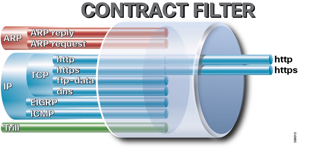
  • Filters classify traffic according to Layer 2 through Layer 4 attributes.

  • Filter entries define the traffic-matching criteria within a filter.

  • Actions specify how to handle filtered traffic. Available actions include permit, mark, redirect, copy, block, and log.

  • Aliases provide optional names that you can change for contract objects.

Figure 6. Contract filters


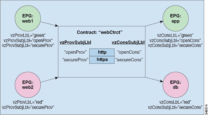
Figure 7. Contracts determine EPG-to-EPG communication


Web service contract

For example, you can define an HTTP filter for TCP ports 80 and 8080 and an HTTPS filter for TCP port 443.

You can then create a webCtrct contract with two sets of subjects. The openProv and openCons subjects contain the HTTP filter. The secureProv and secureCons subjects contain the HTTPS filter.

The webCtrct contract allows secure and nonsecure web traffic between EPGs that provide the web service and EPGs that contain endpoints that consume the service.

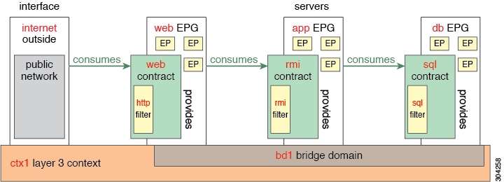
Three-tier application deployment

A three-tier application deployment separates application components into web, application, and database tiers.

  • The web tier uses Hypertext Transfer Protocol (HTTP) filters.

  • The application tier uses Remote Method Invocation (RMI) filters and contracts.

  • The database tier uses Structured Query Language (SQL) filters and contracts.

Three-tier application components

To deploy an application policy, create the required application profiles, filters, and contracts. The APIC fabric typically hosts the three-tier application within a tenant network.

The HTTP filter applies to the web tier, the RMI filter applies to the application tier, and the SQL filter applies to the database tier. The application tier consumes the SQL contract to communicate with the database tier. The web tier consumes the RMI contract to communicate with the application tier.

Traffic enters through the web tier and flows to the application tier. The application tier then communicates with the database tier. The application can also communicate with external networks.

Figure 8. Three-tier application

Parameters for an HTTP filter

The filter contains separate entries for HTTP and HTTPS destination ports.

Parameter

HTTP filter value

Name

http

Number of entries

2

Entry name

Dport-80

Dport-443

EtherType

IP

Protocol

tcp

tcp

Destination port

http

https

Parameters for RMI and SQL filters

The following table lists the configuration values for the RMI and SQL filters.

Parameter

RMI filter value

SQL filter value

Name

rmi

sql

Number of entries

1

1

Entry name

Dport-1099

Dport-1521

EtherType

IP

IP

Protocol

tcp

tcp

Destination port

1099

1521

Application profile database example

The following table shows the contract relationships among the endpoint groups (EPGs) in a three-tier application.

Table 1. Application profile database

EPG

Provided contract

Consumed contract

web

web

rmi

app

rmi

sql

db

sql

None

Create an application profile by using the GUI

Procedure


Step 1

On the menu bar, choose Tenants. In the Navigation pane, expand the tenant, right-click Application Profiles, and choose Create Application Profile.

The Create Application Profile dialog appears.

Step 2

In the Name field, enter a name for the application profile, such as OnlineStore.

Step 3

Click Submit.

The application profile is created.


Create EPGs by using the GUI

The port the EPG uses must belong to one of the VM Managers (VMM) or physical domains associated with the EPG.

Procedure


Step 1

On the menu bar, choose Tenants, and then choose the tenant in which you want to create an endpoint group (EPG).

Step 2

In the Navigation pane, expand tenant_name > Application Profiles > application_profile_name .

Step 3

Right-click Application EPGs, choose Create Application EPG, and configure the EPG.

  1. In the Create Application EPG dialog, enter an EPG name, such as db, in the Name field.

  2. From the Bridge Domain drop-down list, choose a bridge domain, such as bd1.

  3. Check the Associate to VM Domain Profiles check box, and then click Next.

  4. In the STEP 2 > Domains area, expand Associate VM Domain Profiles, and then choose the virtual machine manager (VMM) domain from the drop-down list.

  5. From the Deployment Immediacy drop-down list, retain the default value or choose when the Cisco APIC deploys policies to the physical leaf switch.

  6. From the Resolution Immediacy drop-down list, choose when the physical leaf switch deploys policies to the virtual leaf switch.

    For Cisco AVS, choose Immediate or On Demand. For Cisco ACI Virtual Edge or VMware VDS, choose Immediate, On Demand, or Pre-provision.

  7. (Optional) In the Delimiter field, enter |, ~, !, @, ^, +, or =.

    If you do not specify a delimiter, the system uses | in the VMware port group name.

  8. If you use Cisco ACI Virtual Edge or Cisco AVS, choose an encapsulation mode from the Encap Mode drop-down list.

    The following encapsulation modes are available:

    • VXLAN: Overrides the VLAN configuration of the domain and configures the EPG to use VXLAN encapsulation. The system raises a fault for the EPG if the domain does not have a multicast pool.

    • VLAN: Overrides the VXLAN configuration of the domain and configures the EPG to use VLAN encapsulation. The system raises a fault for the EPG if the domain does not have a VLAN pool.

    • Auto: Configures the EPG to use the encapsulation mode of the VMM domain. This option is the default.

  9. If you use Cisco ACI Virtual Edge, choose native or AVE from the Switching Mode drop-down list.

    If you choose native, the VMware VDS switches the EPG. If you choose AVE, the Cisco ACI Virtual Edge switches the EPG. The default is native.

  10. Click Update, and then click Finish.

Step 4

Repeat the preceding step to create the app and web EPGs. Configure the db, app, and web EPGs in the same bridge domain and data center.


Configuring Contracts Using the APIC GUI

Guidelines and limitations for contracts and filters

The following guidelines describe EtherType match support for contract filters.

  • If the fabric consists of first-generation Cisco Nexus 9300 leaf switches, only IP is supported as an EtherType match in a contract filter. First-generation models include the Cisco Nexus 93128TX, 93120TX, 9396TX, 9396PX, 9372PX, 9372PX-E, 9372TX, and 9372TX-E switches.

  • More-specific EtherType values, such as IPv4 and IPv6, are supported only on leaf switch models with an -EX, -FX, or -FX2 suffix.

Create filters by using the GUI

This example creates separate HTTP, RMI, and SQL filters. The procedure first creates the HTTP filter. Use the same process to create the RMI and SQL filters.

Before you begin

Verify that the tenant, network, and bridge domain are configured.

Procedure


Step 1

On the menu bar, choose Tenants.

Step 2

In the Navigation pane, expand tenant-name > Contracts, right-click Filters, and choose Create Filter.

Step 3

In the Create Filter dialog, create the HTTP filter and its first entry.

  1. In the Name field, enter http.

  2. In the Entries table, click +. In the Name field, enter Dport-80.

  3. From the EtherType drop-down list, choose IP.

  4. From the IP Protocol drop-down list, choose tcp.

  5. Under Destination Port/Range, choose http in the From and To fields.

  6. Click Update, and then click Submit.

    The new filter appears in the Navigation and Work panes.

Note


The ARP Flag field in the Entries table is not configurable and has no effect. Ignore this field.

Step 4

Add an HTTPS entry to the HTTP filter.

  1. Select the http filter, and then click + in the Entries table.

  2. In the Name field, enter Dport-443.

  3. From the EtherType drop-down list, choose IP.

  4. From the IP Protocol drop-down list, choose tcp.

  5. Under Destination Port/Range, choose https in the From and To fields.

  6. Click Update, and then click Submit.

Step 5

Use the same process to create the rmi and sql filters. Use the parameters in Parameters for RMI and SQL filters.


Create contracts by using the GUI

Procedure


Step 1

On the menu bar, choose Tenants, and then choose the tenant in which you want to create the contract. In the Navigation pane, expand tenant-name > Contracts.

Step 2

Right-click Standard, and then choose Create Contract.

The Create Contract dialog appears.

Step 3

Create the contract and associate a filter with its subject.

  1. In the Name field, enter a contract name, such as web.

  2. Next to Subjects, click +.

    The Create Contract Subject dialog appears.

  3. In the Name field, enter a subject name, such as web.

  4. In the Filter Chain area, click + next to Filters.

    This action associates a previously created filter with the contract subject.

  5. From the drop-down list, choose the filter, such as http, and then click Update.

Step 4

In the Create Contract Subject dialog, click OK.

Step 5

In the Create Contract dialog, click Submit.

The contract is created.

Step 6

Repeat this procedure to create the rmi and sql contracts. Associate the rmi filter with the rmi contract subject and the sql filter with the sql contract subject.


Associate provided and consumed contracts by using the GUI

Associate existing contracts with endpoint groups (EPGs) to create policy relationships among the EPGs.

The provider and consumer EPGs must reference the same contract.

Procedure


Step 1

In the APIC GUI, drag from the db EPG icon to the app EPG icon.

Note


The db, app, and web EPGs appear as icons.

The Add Consumed Contract dialog appears.

Step 2

From the Name drop-down list, choose the sql contract, and then click OK.

The db EPG provides the sql contract, and the app EPG consumes it.

Step 3

Drag from the app EPG icon to the web EPG icon.

The Add Consumed Contract dialog appears.

Step 4

From the Name drop-down list, choose the rmi contract, and then click OK.

The app EPG provides the rmi contract, and the web EPG consumes it.

Step 5

Click the web EPG icon, and then click + in the Provided Contracts area.

The Add Provided Contract dialog appears.

Step 6

From the Name drop-down list, choose the web contract, and then click OK.

The web EPG provides the web contract.

Step 7

Click Submit.

The three-tier application profile named OnlineStore is created.

Step 8

In the Navigation pane, expand Application Profiles, and then click OnlineStore.

The Work pane displays the app, db, and web EPGs.

Step 9

In the Work pane, choose Operational > Contracts.

The GUI displays the EPGs and their provided and consumed contract relationships.


Optimize Contract Performance

Contract performance optimization

Ternary content-addressable memory (TCAM) optimization, also called policy compression, stores compatible bidirectional contract rules more efficiently in hardware.

  • Is supported on second-generation Cisco Nexus 9000 Series top-of-rack switches with an -EX, -FX, -FX2, or later product ID suffix.

  • Requires the Enable Policy Compression directive on contract subjects.

  • Requires the reverse port option for filters that specify TCP or UDP ports.

Policy compression configuration and limitations

To optimize TCAM storage for contract rules, complete the following configuration:

  • Configure the contract to apply in both directions between the provider and consumer EPGs.

  • For filters that specify TCP or UDP ports, enable the reverse port option.

  • When you configure the contract subject, select Enable Policy Compression. This directive adds the no_stats option to the action attribute of the actrl:Rule managed object.

The following limitations apply to policy compression:

  • Per-rule statistics are not available. Combined hardware statistics for both directions remain available.

  • After you upgrade to Cisco APIC release 3.2(1), delete and reconfigure contract subjects that were created before the upgrade to enable policy compression.

  • Rules with a priority other than fully_qual are not compressed.

  • Opposite-direction rules are not compressed if properties such as action, including directives, prio, qos, or markDscp, are not identical.

  • Rules that use Implicit or implarp filters are not compressed.

  • Rules with the Deny, Redir, Copy, or Deny-log action are not compressed.

Table 2. Compression matrix

Reverse filter port enabled

TCP or UDP source port

TCP or UDP destination port

Compressed

Yes

Port A

Port B

Yes

Yes

Unspecified

Port B

Yes

Yes

Port A

Unspecified

Yes

Yes

Unspecified

Unspecified

Yes

No

Port A

Port B

No

No

Unspecified

Port B

No

No

Port A

Unspecified

No

No

Unspecified

Unspecified

Yes

Configure a contract for optimized TCAM use by using the GUI

Use this procedure to configure a contract that optimizes the storage of contract rules in hardware ternary content-addressable memory (TCAM).

Before you begin

  • Create the tenant, VRF, and endpoint groups (EPGs) that will provide and consume the contract.

  • Create one or more filters that define the traffic that the contract permits or denies.

Procedure


Step 1

On the menu bar, choose Tenants, and then choose the tenant in which you want to create the contract. In the Navigation pane, expand tenant-name > Contracts.

Step 2

Right-click Standard, and then choose Create Contract.

The Create Contract dialog appears.

Step 3

Create the contract and configure policy compression on its subject.

  1. In the Name field, enter a name for the contract.

  2. Next to Subjects, click +.

    The Create Contract Subject dialog appears.

  3. In the Name field, enter a name for the contract subject.

  4. Ensure that Apply Both Directions and Reverse Filter Ports are enabled.

  5. Next to Filters, click +.

  6. Choose a default filter or a previously configured filter from the drop-down list, or choose Create Filter.

    This action associates the filter with the contract subject.

  7. In the Directives field, choose Enable Policy Compression.

  8. In the Action field, choose Permit.

    Note


    Policy compression does not support the Deny action. Optimization occurs only when the action is Permit.

  9. (Optional) In the Priority field, choose the priority level.

  10. Click Update.

Step 4

In the Create Contract Subject dialog, click OK.

Step 5

In the Create Contract dialog, click Submit.

The contract is created with policy compression enabled.


Policy compression

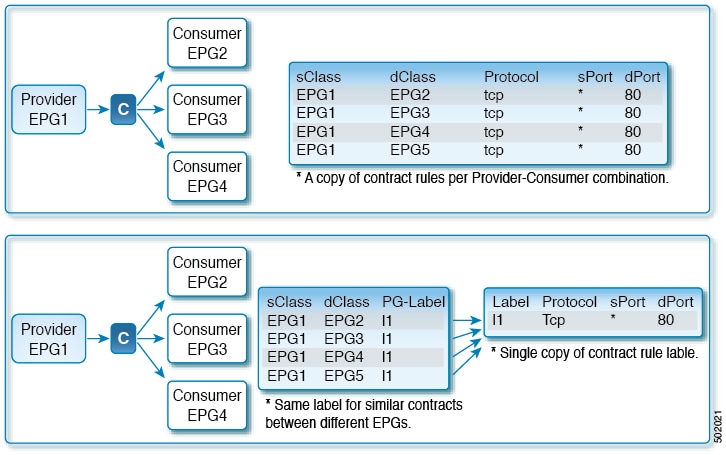
Policy compression is a fabric optimization feature that uses policy group labels to associate multiple identical filter rules with a shared ternary content-addressable memory (TCAM) entry.

  • Allows multiple provider and consumer EPG pairs with identical filter rules to share one TCAM entry.

  • Uses policy group labels to create indirect associations between policies and TCAM entries.

  • Increases the total number of filter rules that the fabric can support.

Policy compression operation

The following figure shows a one-to-many configuration in which indirect associations through policy group labels reduce the number of TCAM entries and increase the number of filter rules that the fabric can support.

Figure 9. Policy compression

Note


Enabling policy compression prevents the system from tracking statistics for individual contracts because multiple contracts share the same TCAM entry.


Guidelines and limitations for policy compression

Observe the following guidelines and limitations when you enable policy compression for contracts.

The following guidelines and limitations apply to policy compression:

  • Policy compression disables statistics for individual filter rules. Identical filter rules from different contracts share ternary content-addressable memory (TCAM) space, so the system does not retain statistics for each rule. Enabling policy compression for a contract discards any existing individual rule statistics.

    To retain individual rule statistics for a contract, do not enable policy compression for that contract.

  • Policy compression is supported on Cisco Nexus 9300-FX and later platforms.

  • Policy compression applies only to user-defined rules. You cannot enable policy compression for implicit rules that the Cisco APIC creates.

  • Policy compression applies only to permit and permit-log rules. The system ignores the policy compression setting for copy, redir, deny, and deny-log rules.

  • You cannot enable policy compression on contracts that have labels or subject exceptions associated with them.

  • Policy compression applies only to contracts for which it is explicitly enabled. If multiple contracts use the same filter, enable policy compression on each contract that you want to compress.

  • You can enable policy compression on only one contract for each EPG pair.

  • The size of the table that maps source and destination classes to labels depends on the policy profile. For scale information, see the Verified Scalability Guide.

    When the table is full, the system stores additional contracts in uncompressed format.

    To view the current capacity usage in the Cisco APIC GUI, choose Operations > Capacity Dashboard > Leaf Capacity.

  • TCAM space is not reduced unless policy compression is enabled. The system dynamically partitions TCAM space when the feature is enabled. If you delete all rules that have policy compression enabled, the system returns the allocated TCAM space.

  • If policy compression and bidirectional contracts are both enabled, the compression logic selects the contract that provides the greatest compression.

    Policy compression takes priority over bidirectional contract compression. If the label table is exhausted or lookup collisions occur, the system falls back to bidirectional contract compression.

  • When a switch with many rules reloads, the rules remain uncompressed until the switch receives the end-of-bootstrap indication.

  • When you upgrade to release 4.0(1) and enable policy compression, delete and reconfigure the contracts if the source release is 3.2(1) or later.

  • When you upgrade to release 4.0(1) and enable policy compression, delete and reconfigure the contracts and filters if the source release is earlier than 3.2(1).

Enable policy compression by using the APIC GUI

Enable policy compression on an existing contract subject filter to reduce the TCAM space required for compatible contract rules.

Procedure


Step 1

Log in to the APIC GUI.

Step 2

In the Navigation pane, choose Tenants > tenant-name > Contracts > Standard > contract-name > subject-name .

Step 3

In the Filters table, double-click the filter for which you want to enable policy compression.

The Filter dialog appears.

Step 4

Check the Enable Policy Compression check box.

Step 5

Click Submit.

Policy compression is enabled for the contract filter.


Contract and Subject Exceptions

Contract and subject exceptions

Contract and subject exceptions use regular expressions to prevent matching endpoint groups (EPGs) from consuming or providing services through a contract.

  • Support inter-EPG and intra-EPG contracts.

  • Apply at the contract level or to an individual contract subject.

  • Support integration with labels, counters, and permit or deny logging.

Exception criteria

Contract and subject exceptions support regular expressions that match the following object attributes:

Table 3. Contract exception criteria

Exception criterion

Example

Description

Tenant

<vzException consRegex="common" field="Tenant" name="excep03" provRegex="t1"/>

Excludes EPGs in the common tenant from consuming contracts that EPGs in the t1 tenant provide.

VRF

<vzException consRegex="ctx1" field="Ctx" name="excep05" provRegex="ctx1"/>

Excludes members of ctx1 from consuming services that members of the same VRF provide.

EPG

<vzException consRegex="EPgPa.*" field="EPg" name="excep03" provRegex="EPg03"/>

Excludes EPGs with names that begin with EPgPa from consuming the contract that EPg03 provides.

DN

<vzException consRegex="uni/tn-t36/ap-customer/epg-epg193" field="Dn" name="excep04" provRegex="uni/tn-t36/ap-customer/epg-epg200"/>

Excludes epg193 from consuming the contract that epg200 provides.

Tag

<vzException consRegex="red" field="Tag" name="excep01" provRegex="green"/>

Excludes objects with the red tag from consuming the contract that objects with the green tag provide.

Configure a contract or subject exception by using the GUI

In this procedure, you configure a contract that permits communication among most endpoint groups (EPGs) but excludes a specified subset of consumer and provider EPGs.

Before you begin

Configure the tenant, VRF, application profile, and EPGs that will provide and consume the contract.

Procedure


Step 1

On the menu bar, choose Tenants > All Tenants.

Step 2

Double-click the tenant in which you want to create the contract.

Step 3

In the Navigation pane, expand Contracts, right-click Filters, and choose Create Filter.

A filter functions as an access control list (ACL) that classifies the traffic to permit or deny through a contract. You can create multiple filters to classify different types of traffic.

Step 4

Enter a name for the filter, add the criteria that identify the traffic to permit or deny, and then click Submit.

Step 5

Right-click Standard, and then choose Create Contract.

Step 6

Enter a name for the contract, configure its scope, and click + to add a subject.

Step 7

(Optional) Repeat the preceding step to add another subject.

Step 8

Click Submit.

Step 9

To configure an exception that applies to every subject in the contract, complete the following substeps:

  1. Click the contract, and then click Contract Exception.

  2. Configure the subjects and specify whether to permit or deny their matching traffic.

  3. Click + to add a contract exception.

  4. Enter a name for the exception and choose the exception criterion.

  5. In the Consumer Regex and Provider Regex fields, enter regular expressions that identify the EPGs to exclude from every subject in the contract.

Step 10

To configure an exception that applies to one subject in the contract, complete the following substeps:

  1. Click the subject, and then click Subject Exception.

  2. Click + to add a subject exception.

  3. Enter a name for the exception and choose the exception criterion.

  4. In the Consumer Regex and Provider Regex fields, enter regular expressions that identify the EPGs to exclude from the selected subject.


Intra-EPG Contracts

Intra-EPG contracts

An intra-EPG contract is a policy that provides granular control over traffic between endpoints in the same endpoint group (EPG).

  • Filters selected traffic within an EPG.

  • Supports application EPGs and microsegmented EPGs (uSeg EPGs).

  • Requires Cisco APIC release 3.0(1) or later.

Intra-EPG communication modes

The following configuration modes control communication between endpoints in an EPG:

  • By default, all endpoints in the EPG can communicate without restriction.

  • Intra-EPG isolation blocks all communication between endpoints in the EPG.

  • An intra-EPG contract permits traffic that matches the contract filters and blocks all other communication between endpoints in the EPG.

Intra-EPG contract scenarios

You can use an intra-EPG contract to permit web traffic while blocking all other traffic. You can also permit all Internet Control Message Protocol (ICMP) traffic and TCP traffic on port 22 while blocking all other communication.

Guidelines and limitations for intra-EPG contracts

Observe the following guidelines and limitations when you deploy intra-EPG contracts on application EPGs, microsegmented EPGs, and L3Out EPGs.

The following guidelines and limitations apply to intra-EPG contracts:

  • Intra-EPG contracts are supported for application EPGs and microsegmented EPGs (uSeg EPGs) on VMware VDS, Open vSwitch (OVS), and bare-metal servers.

    OVS is available with Kubernetes integration for Cisco Application Centric Infrastructure ( ACI ). In Kubernetes, you can create EPGs and assign namespaces to them. You can then use the Cisco Application Policy Infrastructure Controller ( APIC ) to apply intra-EPG policies to the EPGs as you would for VMware VDS or bare-metal servers.

  • Intra-EPG contracts require leaf switches that support proxy Address Resolution Protocol (ARP).

    Intra-EPG contracts are supported on Cisco Nexus 9000 Series switches with an -EX or -FX suffix and on later models.

  • Intra-EPG contracts are not supported in Cisco Application Virtual Switch, Cisco ACI Virtual Edge, or Microsoft domains. Attempting to enforce an intra-EPG contract in these domains can cause ports to enter a blocked state.

  • A service graph cannot be associated with a subject of an intra-EPG contract that has a deny action.

  • Service graph support for intra-EPG contracts is limited to single-node, one-arm mode policy-based redirect and copy services.

  • Beginning with Cisco APIC release 5.2(1), intra-EPG contracts are supported on L3Out EPGs.

  • An intra-EPG contract on an L3Out EPG supports the permit, deny, and redirect actions. The redirect action requires a service graph with policy-based redirect (PBR).

  • An L3Out EPG with the prefix 0.0.0.0/0 or ::/0 cannot use an intra-EPG contract or intra-EPG isolation. The Cisco APIC raises a fault for either configuration.

    To match all IPv4 traffic, you can instead configure the 0.0.0.0/1 and 128.0.0.0/1 prefixes for the L3Out EPG.

  • Unlike an intra-EPG contract on an application EPG, an intra-EPG contract on an L3Out EPG does not automatically include an implicit deny rule. Enable intra-EPG isolation to deny traffic that the contract does not permit.

  • Intra-EPG isolation on an L3Out EPG operates only when the VRF is in enforced mode.

  • Cisco ACI cannot control how traffic reaches the Cisco ACI border leaf switch for intra-L3Out enforcement.

Add an intra-EPG contract by using the GUI

After you configure a contract, you can associate it with an EPG as an intra-EPG contract. The procedure applies to VMware VDS, Open vSwitch (OVS), and bare-metal server environments.

Before you begin

  • Configure an application EPG, microsegmented EPG (uSeg EPG), or L3Out EPG.

  • Configure a contract with the required filters. For more information, see Create contracts by using the GUI.

Procedure


Step 1

On the menu bar, choose Tenants > All Tenants.

Step 2

In the Work pane, double-click the tenant name.

Step 3

Complete the steps for the type of EPG to which you want to add the contract.

  • For an application EPG:

    1. In the Navigation pane, expand tenant_name > Application Profiles > application_profile_name > Application EPGs > epg_name .

    2. Right-click Contracts, and then choose Add Intra-EPG Contract.

    3. In the Add Intra Ext-EPG Contract dialog, choose an existing contract from the Contract drop-down list or create a contract.

    4. Click Submit.

  • For a uSeg EPG:

    1. In the Navigation pane, expand tenant_name > Application Profiles > application_profile_name > uSeg EPGs > epg_name .

    2. Right-click Contracts, and then choose Add Intra-EPG Contract.

    3. In the Add Intra Ext-EPG Contract dialog, choose an existing contract from the Contract drop-down list or create a contract.

    4. Click Submit.

  • For an L3Out EPG:

    1. In the Navigation pane, choose tenant_name > Networking > L3Outs > l3out_name > External EPGs > external_epg_name .

    2. In the Work pane, set Intra Ext-EPG Isolation to Enforced.

    3. Click Submit.

    4. In the Work pane, choose Policy > Contracts.

    5. From the Actions menu, choose Add Intra Ext-EPG Contract.

    6. In the Add Intra Ext-EPG Contract dialog, choose an existing contract from the Contract drop-down list or create a contract.

    7. Click Submit.

The contract appears in the Contract Type: Intra EPG Contract section of the Work pane.


Add an intra-EPG contract to an L3Out EPG by using the NX-OS-style CLI

After you configure a contract, you can associate it with an external Layer 3 EPG as an intra-EPG contract. Enable intra-EPG isolation to block traffic that the contract does not permit.

Before you begin

  • Configure an L3Out EPG.

  • Configure a contract with the required filters.

Procedure


Step 1

Enter global configuration mode.

Example:

apic1# configure

Step 2

Create or select the tenant.

Example:

apic1(config)# tenant Tenant-l3out

Step 3

Create or select the external Layer 3 EPG.

Example:

apic1(config-tenant)# external-l3 epg ext-epg

Step 4

Associate the external Layer 3 EPG with the VRF.

Example:

apic1(config-tenant-l3ext-epg)# vrf member vrf1

Step 5

Enable intra-EPG isolation.

Example:

apic1(config-tenant-l3ext-epg)# isolation enforce

To disable intra-EPG isolation later, enter no isolation enforce.

Step 6

Associate the intra-EPG contract with the external Layer 3 EPG.

Example:

apic1(config-tenant-l3ext-epg)# contract intra-epg contr-intra

The contract permits matching traffic between endpoints in the external Layer 3 EPG. Intra-EPG isolation blocks other traffic.


Configure an intra-EPG contract by using the REST API

Before you begin

  • Configure an endpoint group (EPG).

  • Configure a contract with the required filters.

Procedure


Step 1

Configure the fabric access policies required by the example by sending an XML POST request with a payload similar to the following example:

Example:

<?xml version="1.0" encoding="UTF-8"?>
            <polUni>
            <infraInfra>
            <infraAccPortP name="Ports-1-12" status="deleted"/>
            <!-- VMM VLAN range -->
            <fvnsVlanInstP name="test" allocMode="dynamic">
            <fvnsEncapBlk name="encap" from="vlan-10" to="vlan-100"/>
            </fvnsVlanInstP>
            <!-- Static VLAN range -->
            <fvnsVlanInstP name="test" allocMode="static">
            <fvnsEncapBlk name="default" from="vlan-101" to="vlan-4095"/>
            </fvnsVlanInstP>
            <infraAttEntityP name="test">
            <infraRsDomP tDn="uni/phys-test"/>
            <infraRsDomP tDn="uni/l3dom-test"/>
            <infraRsDomP tDn="uni/vmmp-VMware/dom-test"/>
            </infraAttEntityP>
            <!-- Node profile -->
            <infraNodeP name="test">
            <infraLeafS name="test" type="range">
            <infraNodeBlk name="default" from_="101" to_="102"/>
            </infraLeafS>
            <infraRsAccPortP tDn="uni/infra/accportprof-test"/>
            </infraNodeP>
            <!-- Port profile -->
            <infraAccPortP name="test">
            <!-- 12 regular ports -->
            <infraHPortS name="ports1Through12" type="range">
            <infraPortBlk name="default" fromCard="1" toCard="1" fromPort="1" toPort="12"/>
            <infraRsAccBaseGrp tDn="uni/infra/funcprof/accportgrp-test"/>
            </infraHPortS>
            <!-- Two ports in a port channel -->
            <infraHPortS name="portsForPc1" type="range">
            <infraPortBlk name="default" fromCard="1" toCard="1" fromPort="13" toPort="14"/>
            <infraRsAccBaseGrp tDn="uni/infra/funcprof/accbundle-testPc"/>
            </infraHPortS>
            <!-- Two ports in a port channel -->
            <infraHPortS name="portsForPc2" type="range">
            <infraPortBlk name="blk1" fromCard="1" toCard="1" fromPort="15" toPort="16"/>
            <infraRsAccBaseGrp tDn="uni/infra/funcprof/accbundle-pc"/>
            </infraHPortS>
            <!-- Two ports in a port channel for a FEX -->
            <infraHPortS name="portsForFex" type="range">
            <infraPortBlk name="blk1" fromCard="1" toCard="1" fromPort="17" toPort="18"/>
            <infraRsAccBaseGrp tDn="uni/infra/fexprof-default/fexbundle-test" fexId="111"/>
            </infraHPortS>
            <!-- Two ports in a vPC -->
            <infraHPortS name="portsForVpc" type="range">
            <infraPortBlk name="blk1" fromCard="1" toCard="1" fromPort="19" toPort="20"/>
            <infraRsAccBaseGrp tDn="uni/infra/funcprof/accbundle-testVpc"/>
            </infraHPortS>
            </infraAccPortP>
            <!-- FEX profile -->
            <infraFexP name="default">
            <infraFexBndlGrp name="default"/>
            <!-- 12 FEX ports -->
            <infraHPortS name="ports1Through12" type="range">
            <infraPortBlk name="default" fromCard="1" toCard="1" fromPort="1" toPort="12"/>
            <infraRsAccBaseGrp tDn="uni/infra/funcprof/accportgrp-test"/>
            </infraHPortS>
            <!-- Three ports in a FEX port channel -->
            <infraHPortS name="portsForPc" type="range">
            <infraPortBlk name="blk1" fromCard="1" toCard="1" fromPort="13" toPort="16"/>
            <infraRsAccBaseGrp tDn="uni/infra/funcprof/accbundle-testPcOnFex"/>
            </infraHPortS>
            <!-- Three ports in a FEX vPC -->
            <infraHPortS name="portsForVpc" type="range">
            <infraPortBlk name="blk1" fromCard="1" toCard="1" fromPort="17" toPort="19"/>
            <infraRsAccBaseGrp tDn="uni/infra/funcprof/accbundle-testVpcOnFex"/>
            </infraHPortS>
            </infraFexP>
            <!-- Functional profile -->
            <infraFuncP>
            <!-- Regular port group -->
            <infraAccPortGrp name="test">
            <infraRsAttEntP tDn="uni/infra/attentp-test"/>
            </infraAccPortGrp>
            <!-- Port channel -->
            <infraAccBndlGrp name="testPc" lagT="link">
            <infraRsLacpPol tnLacpLagPolName="testPc"/>
            <infraRsAttEntP tDn="uni/infra/attentp-test"/>
            </infraAccBndlGrp>
            <!-- vPC -->
            <infraAccBndlGrp name="testVpc" lagT="node">
            <infraRsLacpPol tnLacpLagPolName="testVpc"/>
            <infraRsAttEntP tDn="uni/infra/attentp-test"/>
            </infraAccBndlGrp>
            <!-- Port channel on a FEX -->
            <infraAccBndlGrp name="testPcOnFex" lagT="link">
            <infraRsLacpPol tnLacpLagPolName="testPcOnFex"/>
            <infraRsAttEntP tDn="uni/infra/attentp-test"/>
            </infraAccBndlGrp>
            <!-- vPC on a FEX -->
            <infraAccBndlGrp name="testVpcOnFex" lagT="node">
            <infraRsLacpPol tnLacpLagPolName="testVpcOnFex"/>
            <infraRsAttEntP tDn="uni/infra/attentp-test"/>
            </infraAccBndlGrp>
            </infraFuncP>
            <!-- Link aggregation policies -->
            <lacpLagPol name="testPc" minLinks="1" maxLinks="10"/>
            <lacpLagPol name="testVpc" minLinks="1" maxLinks="10"/>
            <lacpLagPol name="testPcOnFex" minLinks="2" maxLinks="5"/>
            <lacpLagPol name="testVpcOnFex" minLinks="2" maxLinks="10"/>
            </infraInfra>
            <fabricInst>
            <fabricProtPol name="testVpc">
            <fabricExplicitGEp name="testVpc" id="101">
            <fabricNodePEp id="101"/>
            <fabricNodePEp id="102"/>
            </fabricExplicitGEp>
            </fabricProtPol>
            </fabricInst>
            <physDomP name="test">
            <infraRsVlanNs tDn="uni/infra/vlanns-test-static"/>
            </physDomP>
            <l3extDomP name="test">
            <infraRsVlanNs tDn="uni/infra/vlanns-test-static"/>
            </l3extDomP>
            </polUni>

Step 2

Configure the tenant and intra-EPG contract associations by sending an XML POST request with a payload similar to the following example:

Example:

<?xml version="1.0" encoding="UTF-8"?>
            <polUni>
            <fvTenant name="Tenant-l3out">
            <vzBrCP intent="install" name="contr-intra" scope="context">
            <vzSubj consMatchT="AtleastOne" name="subj" revFltPorts="yes">
            <vzRsSubjFiltAtt action="permit" priorityOverride="default"
            tnVzFilterName="flt-ssh"/>
            </vzSubj>
            </vzBrCP>
            <vzBrCP intent="install" name="contr2" scope="context">
            <vzSubj consMatchT="AtleastOne" name="contr2-subj" revFltPorts="yes">
            <vzRsSubjFiltAtt action="permit" priorityOverride="default"
            tnVzFilterName="flt-ftp"/>
            </vzSubj>
            </vzBrCP>
            <vzBrCP intent="install" name="contr1" scope="context">
            <vzSubj consMatchT="AtleastOne" name="subj-http" revFltPorts="yes">
            <vzRsSubjFiltAtt action="deny" priorityOverride="default"
            tnVzFilterName="flt-http"/>
            </vzSubj>
            </vzBrCP>
            <l3extOut enforceRtctrl="export" mplsEnabled="no" name="l3out1">
            <l3extRsL3DomAtt tDn="uni/l3dom-test"/>
            <l3extRsEctx tnFvCtxName="vrf1"/>
            <l3extLNodeP name="l3out1_nodeProfile" tag="yellow-green">
            <l3extRsNodeL3OutAtt rtrId="172.16.0.1" rtrIdLoopBack="yes"
            tDn="topology/pod-1/node-101"/>
            <l3extLIfP name="l3out1_interfaceProfile" tag="yellow-green">
            <l3extRsPathL3OutAtt addr="192.168.15.1/24" autostate="disabled"
            encap="unknown" encapScope="local" ifInstT="l3-port" ipv6Dad="enabled"
            isMultiPodDirect="no" llAddr="::" mac="00:22:BD:F8:19:FF"
            mode="regular" mtu="inherit"
            tDn="topology/pod-1/paths-101/pathep-[eth1/10]"/>
            </l3extLIfP>
            </l3extLNodeP>
            <!--
            Set pcEnfPref to "enforced" to enable intra-Ext-EPG isolation.
            Set pcEnfPref to "unenforced" to disable intra-Ext-EPG isolation.
            -->
            <l3extInstP floodOnEncap="disabled" matchT="AtleastOne"
            name="l3epg1" pcEnfPref="unenforced" prefGrMemb="exclude">
            <l3extSubnet ip="172.16.0.0/16" scope="import-security"/>
            <fvRsCons tnVzBrCPName="contr2"/>
            <fvRsIntraEpg tnVzBrCPName="contr-intra"/>
            </l3extInstP>
            </l3extOut>
            <fvCtx bdEnforcedEnable="no" ipDataPlaneLearning="enabled" knwMcastAct="permit"
            name="vrf1" pcEnfDir="egress" pcEnfPref="unenforced" vrfIndex="0">
            <fvRsVrfValidationPol/>
            <vzAny matchT="AtleastOne" prefGrMemb="disabled"/>
            </fvCtx>
            <fvBD OptimizeWanBandwidth="no" arpFlood="yes" epClear="no" hostBasedRouting="no"
            intersiteBumTrafficAllow="no" intersiteL2Stretch="no" ipLearning="yes"
            ipv6McastAllow="no" limitIpLearnToSubnets="yes" llAddr="::"
            mac="00:22:BD:F8:19:FF" mcastAllow="no" multiDstPktAct="bd-flood" name="bd-web"
            type="regular" unicastRoute="yes" unkMacUcastAct="proxy" unkMcastAct="flood"
            v6unkMcastAct="flood" vmac="not-applicable">
            <fvSubnet ip="192.168.1.254/24" ipDPLearning="enabled" preferred="no"
            scope="private" virtual="no"/>
            <fvRsCtx tnFvCtxName="vrf1"/>
            <fvRsBdToEpRet resolveAct="resolve"/>
            </fvBD>
            <fvBD OptimizeWanBandwidth="no" arpFlood="yes" epClear="no" hostBasedRouting="no"
            intersiteBumTrafficAllow="no" intersiteL2Stretch="no" ipLearning="yes"
            ipv6McastAllow="no" limitIpLearnToSubnets="yes" llAddr="::"
            mac="00:22:BD:F8:19:FF" mcastAllow="no" multiDstPktAct="bd-flood" name="bd-app"
            type="regular" unicastRoute="yes" unkMacUcastAct="proxy" unkMcastAct="flood"
            v6unkMcastAct="flood" vmac="not-applicable">
            <fvSubnet ip="192.168.2.254/24" ipDPLearning="enabled" preferred="no"
            scope="private" virtual="no"/>
            <fvRsCtx tnFvCtxName="vrf1"/>
            <fvRsBdToEpRet resolveAct="resolve"/>
            </fvBD>
            <vzFilter name="flt-ftp">
            <vzEntry applyToFrag="no" arpOpc="unspecified" dFromPort="ftpData"
            dToPort="ftpData" etherT="ipv4" icmpv4T="unspecified" icmpv6T="unspecified"
            matchDscp="unspecified" name="ftp" prot="tcp" sFromPort="unspecified"
            sToPort="unspecified" stateful="no"/>
            </vzFilter>
            <vzFilter name="flt-ssh">
            <vzEntry applyToFrag="no" arpOpc="unspecified" dFromPort="ssh" dToPort="ssh"
            etherT="ipv4" icmpv4T="unspecified" icmpv6T="unspecified"
            matchDscp="unspecified" name="ssh" prot="tcp" sFromPort="unspecified"
            sToPort="unspecified" stateful="no"/>
            </vzFilter>
            <vzFilter name="flt-http">
            <vzEntry applyToFrag="no" arpOpc="unspecified" dFromPort="http" dToPort="http"
            etherT="ipv4" icmpv4T="unspecified" icmpv6T="unspecified"
            matchDscp="unspecified" name="flt1" prot="tcp" sFromPort="unspecified"
            sToPort="unspecified" stateful="no"/>
            </vzFilter>
            <fvAp name="ap-app1">
            <fvAEPg floodOnEncap="disabled" hasMcastSource="no" isAttrBasedEPg="no"
            matchT="AtleastOne" name="epg-app" pcEnfPref="unenforced"
            prefGrMemb="exclude" shutdown="no">
            <fvRsProv intent="install" matchT="AtleastOne" tnVzBrCPName="contr2"/>
            <fvRsProv intent="install" matchT="AtleastOne" tnVzBrCPName="contr1"/>
            <fvRsPathAtt encap="vlan-103" instrImedcy="immediate" mode="native"
            primaryEncap="unknown" tDn="topology/pod-1/paths-101/pathep-[eth1/3]"/>
            <fvRsDomAtt bindingType="none" classPref="encap" encap="unknown"
            encapMode="auto" epgCos="Cos0" epgCosPref="disabled" instrImedcy="lazy"
            netflowDir="both" netflowPref="disabled" numPorts="0" portAllocation="none"
            primaryEncap="unknown" primaryEncapInner="unknown" resImedcy="immediate"
            secondaryEncapInner="unknown" switchingMode="native" tDn="uni/phys-test"
            untagged="no" vnetOnly="no"/>
            <fvRsBd tnFvBDName="bd-app"/>
            </fvAEPg>
            <fvAEPg floodOnEncap="disabled" hasMcastSource="no"
            isAttrBasedEPg="no" matchT="AtleastOne" name="epg-web" pcEnfPref="unenforced"
            prefGrMemb="exclude" shutdown="no">
            <fvRsPathAtt encap="vlan-104" instrImedcy="immediate" mode="native"
            primaryEncap="unknown" tDn="topology/pod-1/paths-101/pathep-[eth1/4]"/>
            <fvRsDomAtt bindingType="none" classPref="encap" encap="unknown"
            encapMode="auto" epgCos="Cos0" epgCosPref="disabled" instrImedcy="lazy"
            netflowDir="both" netflowPref="disabled" numPorts="0" portAllocation="none"
            primaryEncap="unknown" primaryEncapInner="unknown" resImedcy="immediate"
            secondaryEncapInner="unknown" switchingMode="native" tDn="uni/phys-test"
            untagged="no" vnetOnly="no"/>
            <fvRsCons intent="install" tnVzBrCPName="contr1"/>
            <fvRsBd tnFvBDName="bd-web"/>
            </fvAEPg>
            </fvAp>
            </fvTenant>
            </polUni>

EPG Contract Inheritance

Contract inheritance

Contract inheritance is a policy configuration in which an inheritor endpoint group (EPG) uses the provided and consumed contracts associated with a contract master EPG.

  • Supports application, microsegmented, L2Out, and L3Out EPGs.

  • Propagates contract changes from the contract master EPG to all inheritor EPGs.

  • Allows an EPG to inherit contracts from multiple contract master EPGs.

Contract inheritance guidelines and support

The following guidelines and requirements apply to contract inheritance:

  • Configure inheritance relationships only between EPGs of the same type.

  • The contract master EPG and inheritor EPGs must belong to the same tenant.

  • Contract inheritance supports only one level. You cannot chain inheritance relationships, and a contract master EPG cannot inherit contracts.

  • Labels are supported. For inherited contracts, the APIC uses the label configured on the contract master EPG.

  • Directly associated and inherited contracts both consume ternary content-addressable memory (TCAM) resources.

  • vzAny security contracts and taboo contracts are not supported.

  • Contract inheritance with a service graph is supported in Cisco APIC releases 4.2(6), 5.0(1), and later, when the contract and EPGs belong to the same tenant.

The following figure shows EPG A inheriting contracts from EPG B:

Figure 10. Contract inheritance

Configuration methods

You can configure contract inheritance by using the APIC GUI, the NX-OS-style CLI, or the REST API.

Configuring EPG Contract Inheritance Using the GUI

Configure application EPG contract inheritance by using the GUI

Before you begin

  • Configure the tenant and application profile for the endpoint groups (EPGs).

  • As required, configure the bridge domain for the EPG that will inherit the contracts.

  • Configure at least one application EPG to serve as the contract master EPG.

  • Configure the contracts to inherit and associate them with the contract master EPG.

You can configure contract inheritance for an application EPG in the Basic or Advanced mode of the APIC GUI.

Procedure


Step 1

In the Navigation pane, choose Tenants > tenant-name > Application Profiles > application-profile-name .

Step 2

Right-click Application EPGs, and then choose Create Application EPG.

Step 3

In the Name field, enter a name for the EPG that will inherit the contracts.

Step 4

From the Bridge Domain drop-down list, choose the common or default bridge domain, choose an existing bridge domain, or create a bridge domain for the EPG.

Step 5

For EPG Contract Master, click +, choose the application profile and EPG that will serve as the contract master, and then click Update.

Step 6

Click Finish.

The application EPG is created and inherits the contract associations of the contract master EPG.

Step 7

(Optional) To verify the contract master, choose Tenants > tenant-name > Application Profiles > application-profile-name > Application EPGs > epg-name > General, and then verify the EPG Contract Master value.

Step 8

(Optional) To view the inherited contracts, expand epg-name , and then click Contracts.


Configure uSeg EPG contract inheritance by using the GUI

Before you begin

  • Configure the tenant and application profile for the endpoint groups (EPGs).

  • As required, configure the bridge domain for the uSeg EPG that will inherit the contracts.

  • Configure a uSeg EPG to serve as the contract master EPG.

  • Configure the contracts to inherit and associate them with the contract master EPG.

You can configure contract inheritance for a microsegmented EPG (uSeg EPG) in the Basic or Advanced mode of the APIC GUI.

Procedure


Step 1

In the Navigation pane, choose Tenants > tenant-name > Application Profiles > application-profile-name .

Step 2

Right-click uSeg EPGs, and then choose Create uSeg EPG.

Step 3

In the Name field, enter a name for the uSeg EPG that will inherit the contracts.

Step 4

From the Bridge Domain drop-down list, choose the common or default bridge domain, choose an existing bridge domain, or create a bridge domain for the uSeg EPG.

Step 5

For EPG Contract Master, click +, choose the application profile and uSeg EPG that will serve as the contract master, and then click Update.

Step 6

Click Finish.

The uSeg EPG is created and inherits the contract associations of the contract master EPG.

Step 7

(Optional) To view the inherited contracts, choose Tenants > tenant-name > Application Profiles > application-profile-name > uSeg EPGs > useg-epg-name > Contracts.


Configure L2Out EPG contract inheritance by using the GUI

Before you begin

  • Configure the tenant for the endpoint groups (EPGs).

  • Configure a Layer 2 Outside (L2Out) and the external L2Out EPG (l2extInstP) that will serve as the contract master.

  • Configure the contracts to inherit and associate them with the contract master EPG.

Use the Cisco Application Policy Infrastructure Controller ( APIC ) GUI to configure contract inheritance for an external L2Out EPG.

Procedure


Step 1

In the Navigation pane, choose Tenants > tenant-name > Networking > L2Outs.

Step 2

Expand l2out-name .

Step 3

Right-click External EPGs, and then choose Create External EPG.

Step 4

Enter a name for the external EPG and configure the other attributes as required.

Step 5

Click Submit.

Step 6

Expand External EPGs.

Step 7

Click external-epg-name .

Step 8

In the External EPG pane, click + for L2Out Contract Masters.

Step 9

Select the L2Out and external L2Out EPG that will serve as the contract master.

Step 10

Click Update.

The external L2Out EPG inherits the contract associations of the contract master EPG.

Step 11

(Optional) To view the inherited contracts, click the external EPG name, and then choose Contracts > Inherited Contracts.


Configure external L3Out EPG contract inheritance by using the GUI

Before you begin

Configure the tenant for the endpoint groups (EPGs).

Configure a Layer 3 Outside (L3Out) and the external L3Out EPG (l3extInstP) that will serve as the contract master.

Configure the contracts to inherit and associate them with the contract master EPG.

Use the Cisco Application Policy Infrastructure Controller ( APIC ) GUI to configure contract inheritance for an external L3Out EPG.

Procedure


Step 1

In the Navigation pane, choose Tenants > tenant-name > Networking > L3Outs.

Step 2

Expand l3out-name .

Step 3

Right-click External EPGs, and then choose Create External EPG.

Step 4

Enter a name for the external EPG and configure subnets and other attributes as required.

Step 5

Click Submit.

Step 6

Expand Networks.

Step 7

Click network-name .

Step 8

In the External EPG pane, click + for L3Out Contract Masters.

Step 9

Select the L3Out and external EPG that will serve as the contract master.

Step 10

Click Update.

The external L3Out EPG inherits the contract associations of the contract master EPG.

Step 11

(Optional) To view the inherited contracts, click the external EPG name, and then choose Contracts > Inherited Contracts.


Contract Preferred Groups

Contract preferred groups

A contract preferred group is a policy enforcement mechanism that controls communication among endpoint groups (EPGs) in a VRF according to their membership status.

  • Included EPGs can communicate with each other without contracts because of a default permit rule.

  • Excluded EPGs require contracts to communicate because of a default deny rule.

Contract preferred group operation

A contract preferred group provides granular control over communication among EPGs in a VRF. If most EPGs require unrestricted communication but some require limited communication, include the unrestricted EPGs in the preferred group and use contracts with filters to control communication with the excluded EPGs.

An EPG that is excluded from the preferred group can communicate with another EPG only when a contract overrides the default source-any, destination-any deny rule.

Figure 11. Contract preferred group

Service graph support

Beginning with Cisco APIC release 4.0(1), EPGs that service graphs create can be included in contract preferred groups. The Service EPG Policy defines whether the EPG is included in or excluded from the preferred group. You can apply the policy through a device selection policy or a service graph template.

Shadow EPGs can also be configured as included or excluded members of contract preferred groups.

Limitations

The following limitations apply to contract preferred groups:

  • If an L3Out EPG and an application EPG are included in a contract preferred group, and the application EPG is deployed only on a virtual port channel (vPC), only one leaf switch in the vPC might contain the L3Out prefix entry. The other leaf switch does not contain the entry and drops the traffic.

  • If the provider or consumer EPG in a service graph contract is included in a contract preferred group, the shadow EPG cannot be excluded from the group.

    The shadow EPG is permitted in the contract preferred group but does not trigger deployment of the preferred group policy on its node. To deploy the policy on that node, deploy a dummy EPG that belongs to the contract preferred group.

  • Because of CSCvm63145, an EPG in a contract preferred group can consume a shared-service contract but cannot provide a shared-service contract when an L3Out EPG is the consumer.

To work around the L3Out vPC issue, perform one of the following actions:

  • Disable and reenable the contract preferred group in the VRF.

  • Delete and recreate the prefix entries for the L3Out EPG.

Contract preferred group guidelines and limitations

A contract preferred group allows included endpoint groups (EPGs) in a VRF to communicate without explicit contracts.

Configuration guidelines and limitations

Observe the following guidelines and limitations when you configure contract preferred groups:

  • If an L3Out EPG belongs to a contract preferred group and an external source uses the default route 0.0.0.0/0, the border leaf switches might drop unicast traffic that enters the fabric. This behavior is expected.

  • An external EPG (l3extInstP) that contains the 0.0.0.0/0 prefix cannot be included in a contract preferred group. To match all IPv4 traffic, configure the 0.0.0.0/1 and 128.0.0.0/1 prefixes instead.

  • Contract preferred group EPGs are not supported with GOLF. Use explicit contracts to control communication between an application EPG and an L3Out EPG for GOLF.

Configure a contract preferred group by using the GUI

Before you begin

Configure the tenant, VRF, and endpoint groups (EPGs) that will participate in the contract preferred group.

Procedure


Step 1

On the menu bar, choose Tenants > tenant_name .

Step 2

In the Navigation pane, expand tenant_name > Networking > VRFs.

Step 3

Click the VRF in which you want to enable the contract preferred group.

Step 4

Set Preferred Group to Enabled.

Step 5

Click Submit.

Step 6

In the Navigation pane, expand Application Profiles, and then create or expand an application profile associated with the tenant VRF.

Step 7

Expand Application EPGs, and then click the EPG that you want to include in the contract preferred group.

Step 8

In the Work pane, choose Policy > General.

Step 9

Set Preferred Group Member to Include.

Step 10

Click Submit.

The EPG is included in the contract preferred group.


What to do next

Include the other EPGs that require unrestricted communication with this EPG. Configure contracts to control communication between preferred group members and EPGs that are excluded from the group.


Note


To support contract preferred group members through Layer 4 through Layer 7 service graphs, create an L4-L7 service EPG policy. For more information, see Create an L4-L7 service EPG policy by using the GUI.


Create an L4-L7 service EPG policy by using the GUI

Before you begin

Configure a tenant.

An L4-L7 service EPG policy defines whether EPGs that a service graph creates are included in or excluded from a contract preferred group. Included EPGs can communicate with other included EPGs without contracts.

After you create the policy, you can select it when you apply a service graph template to EPGs.

Procedure


Step 1

On the menu bar, choose Tenants > tenant_name .

Step 2

In the Navigation pane, choose Policies > Protocol > L4-L7 Service EPG Policy.

Step 3

Right-click L4-L7 Service EPG Policy, and then choose Create L4-L7 Service EPG Policy.

The Create L4-L7 Service EPG Policy dialog appears.

Step 4

In the Name field, enter a unique name for the policy.

Step 5

(Optional) In the Description field, enter a description of the policy.

Step 6

In the Preferred Group Member field, choose whether to include or exclude the service EPGs from the contract preferred group.

Step 7

Click Submit.

The policy appears in the Work pane. To edit the policy, double-click its row.


What to do next

Select the L4-L7 service EPG policy when you apply a service graph template to EPGs. For more information, see Applying a Service Graph Template to Endpoint Groups Using the GUI in the Cisco APIC Layer 4 to Layer 7 Services Deployment Guide.

Contracts with Permit and Deny Rules

Contracts with permit and deny rules

A contract can use permit and deny rules to explicitly allow or block traffic between endpoints.

  • Supports permit and deny actions.

  • Supports default, highest, medium, and lowest priorities for deny rules.

  • Resolves matching rule conflicts according to rule priority and contract scope.

Rule priority and conflict resolution

The system uses the following priority hierarchy to resolve rule conflicts:

  • The implicit deny rule has the lowest priority.

  • Contract rules between vzAny objects have a higher priority than the implicit deny rule.

  • Contract rules between specific EPG pairs have a higher priority than rules between vzAny objects.

  • For a contract between a specific EPG pair, a deny rule with the default priority has the same priority as a permit rule for that EPG pair. If traffic matches both rules, the deny rule takes precedence.

  • For a contract between vzAny objects, a deny rule with the default priority has the same priority as a permit rule for that pair. If traffic matches both rules, the deny rule takes precedence.

  • Deny rules with the highest priority are evaluated at the same priority level as EPG-to-EPG contract rules.

  • Deny rules with medium priority are evaluated at the same priority level as vzAny-to-EPG contract rules.

  • Deny rules with the lowest priority are evaluated at the same priority level as vzAny-to-vzAny contract rules.

  • If you lower the priority of a deny rule in a contract between EPGs, a matching permit rule with a higher priority takes precedence.

Enable ACL contract permit or deny logging by using the GUI


Note


For permit logging, configure the contract in the tenant that contains the VRF associated with the endpoint group (EPG). This tenant might differ from the tenant that contains the EPG or its associated contracts.


Procedure


Step 1

On the menu bar, choose Tenants > tenant_name .

Step 2

In the Navigation pane, expand Contracts , right-click Standard , and choose Create Contract .

Step 3

In the Create Contract dialog box, configure the contract.

  1. In the Name field, enter a name for the contract.

  2. In the Scope field, choose VRF , Tenant , or Global .

  3. (Optional) Configure the target differentiated services code point (DSCP) or quality of service (QoS) class for the contract.

  4. Next to Subjects , click + .

Step 4

In the Create Contract Subject dialog box, configure the contract subject.

  1. In the Name field, enter a name for the subject.

  2. (Optional) In the Description field, enter a description.

  3. (Optional) From the Target DSCP drop-down list, choose the DSCP value to apply to the subject.

  4. Keep Apply Both Directions selected to apply the contract in both directions. Clear the option to apply the contract only from the consumer to the provider.

  5. If Apply Both Directions is selected, keep Reverse Filter Ports selected to exchange the Layer 4 source and destination ports for provider-to-consumer traffic.

  6. Next to Filters , click + .

  7. From the Name drop-down list, choose a filter, such as arp , default , est , or icmp .

  8. From the Directives drop-down list, choose log .

  9. For Action , retain the default value of Permit to enable permit logging, or choose Deny to enable deny logging.

    With the log directive enabled, the selected action determines whether the ACL logs record traffic that the subject permits or denies.

  10. (Optional) Set the priority for the subject.

  11. Click Update .

Step 5

In the Create Contract Subject dialog box, click OK .

Step 6

Click Submit .

Permit or deny logging is enabled for the selected contract filter.


Enable ACL contract permit logging by using the NX-OS-style CLI

Procedure


Step 1

Enter the following commands to enable permit logging for a contract subject:

For direction , enter in , out , or both .

Example:

configure
                        tenant tenant_name
                        contract contract_name type permit
                        subject subject_name
                        access-group access_list_name direction log
                        end

The following example enables permit logging for the icmp subject:

apic1# configure
                        apic1(config)# tenant BDMode1
                        apic1(config-tenant)# contract Logicmp type permit
                        apic1(config-tenant-contract)# subject icmp
                        apic1(config-tenant-contract-subj)# access-group arp both log
                        apic1(config-tenant-contract-subj)# end

Permit logging is enabled for traffic that matches the specified access list.

Step 2

(Optional) To disable permit logging later, use the no access-group command in contract-subject configuration mode.

Example:

apic1# configure
                        apic1(config)# tenant BDMode1
                        apic1(config-tenant)# contract Logicmp type permit
                        apic1(config-tenant-contract)# subject icmp
                        apic1(config-tenant-contract-subj)# no access-group arp both log
                        apic1(config-tenant-contract-subj)# end

Enable ACL contract permit and deny logging by using the REST API

In each filter attachment, the @directives attribute enables logging and the @action attribute determines whether the logged traffic is permitted or denied.

Procedure


Send a POST request with an XML payload similar to the following example:

Example:

<vzBrCP dn="uni/tn-Tenant64/brc-C64" name="C64" scope="context">
                        <vzSubj consMatchT="AtleastOne"
                        name="HTTPSsbj"
                        provMatchT="AtleastOne"
                        revFltPorts="yes"
                        rn="subj-HTTPSsbj">
                        <vzRsSubjFiltAtt action="permit"
                        directives="log"
                        forceResolve="yes"
                        priorityOverride="default"
                        rn="rssubjFiltAtt-PerHTTPS"
                        tDn="uni/tn-Tenant64/flt-PerHTTPS"
                        tRn="flt-PerHTTPS"
                        tnVzFilterName="PerHTTPS"/>
                        </vzSubj>
                        <vzSubj consMatchT="AtleastOne"
                        name="httpSbj"
                        provMatchT="AtleastOne"
                        revFltPorts="yes"
                        rn="subj-httpSbj">
                        <vzRsSubjFiltAtt action="deny"
                        directives="log"
                        forceResolve="yes"
                        priorityOverride="default"
                        rn="rssubjFiltAtt-httpFilter"
                        tDn="uni/tn-Tenant64/flt-httpFilter"
                        tRn="flt-httpFilter"
                        tnVzFilterName="httpFilter"/>
                        </vzSubj>
                        <vzSubj consMatchT="AtleastOne"
                        name="subj64"
                        provMatchT="AtleastOne"
                        revFltPorts="yes"
                        rn="subj-subj64">
                        <vzRsSubjFiltAtt action="permit"
                        directives="log"
                        forceResolve="yes"
                        priorityOverride="default"
                        rn="rssubjFiltAtt-icmp"
                        tDn="uni/tn-common/flt-icmp"
                        tRn="flt-icmp"
                        tnVzFilterName="icmp"/>
                        </vzSubj>
                        </vzBrCP>

ACL logging is enabled for the permit and deny actions specified in the payload.


Enable taboo contract deny logging by using the GUI

Apply the log directive to a taboo contract filter to record matching denied traffic.

Procedure


Step 1

On the menu bar, choose Tenants > tenant_name .

Step 2

In the Navigation pane, expand Contracts .

Step 3

Right-click Taboos and choose Create Taboo Contract .

Step 4

In the Create Taboo Contract dialog box, configure the taboo contract.

  1. In the Name field, enter a name for the taboo contract.

  2. (Optional) In the Description field, enter a description.

  3. Next to Subjects , click + .

Step 5

In the Create Taboo Contract Subject dialog box, configure the subject and select a filter.

  1. In the Specify Identity of Subject area, enter a name for the subject.

  2. (Optional) Enter a description of the subject.

  3. Next to Filters , click + .

  4. From the Name drop-down list, choose an existing filter, choose a default filter, or choose Create Filter .

    The default filters include tenant_name /arp , tenant_name /default , tenant_name /est , and tenant_name /icmp .

Step 6

(Optional) If you chose Create Filter , configure the filter.

  1. In the Specify Filter Identity area, enter a name and, optionally, a description.

  2. Expand Entries , enter a name for the entry, and configure the criteria that identify the traffic to deny.

  3. Click Update .

  4. Click OK to create the filter and return to the Create Taboo Contract Subject dialog box.

Step 7

For the selected filter, choose log from the Directives drop-down list, and click Update .

Step 8

In the Create Taboo Contract Subject dialog box, click OK .

Step 9

In the Create Taboo Contract dialog box, click Submit .

Deny logging is enabled for traffic that matches the taboo contract filter.


Enable taboo contract deny logging by using the NX-OS-style CLI

Procedure


Step 1

Enter the following commands to enable deny logging for a taboo contract subject:

Example:

configure
                        tenant tenant_name
                        contract contract_name type deny
                        subject subject_name
                        access-group access_list_name both log
                        end

The following example enables deny logging for the dropftp subject:

apic1# configure
                        apic1(config)# tenant BDMode1
                        apic1(config-tenant)# contract dropFTP type deny
                        apic1(config-tenant-contract)# subject dropftp
                        apic1(config-tenant-contract-subj)# access-group ftp both log
                        apic1(config-tenant-contract-subj)# end

Deny logging is enabled for traffic that matches the specified access list.

Step 2

(Optional) To disable deny logging later, use the no access-group command in contract-subject configuration mode.

Example:

apic1# configure
                        apic1(config)# tenant BDMode1
                        apic1(config-tenant)# contract dropFTP type deny
                        apic1(config-tenant-contract)# subject dropftp
                        apic1(config-tenant-contract-subj)# no access-group ftp both log
                        apic1(config-tenant-contract-subj)# end

Enable taboo contract deny logging by using the REST API

The @directives attribute on the deny-rule relationship enables logging when its value is log.

Procedure


Send a POST request with an XML payload similar to the following example:

Example:

<vzTaboo dn="uni/tn-Tenant64/taboo-TCtrctPrefix"
                        name="TCtrctPrefix" scope="context">
                        <vzTSubj name="PrefSubj" rn="tsubj-PrefSubj">
                        <vzRsDenyRule directives="log"
                        forceResolve="yes"
                        rn="rsdenyRule-default"
                        tCl="vzFilter"
                        tDn="uni/tn-common/flt-default"
                        tRn="flt-default"/>
                        </vzTSubj>
                        </vzTaboo>

Deny logging is enabled for traffic that matches the taboo contract rule.


View ACL permit and deny logs by using the GUI

Before you begin

Enable ACL permit or deny logging and generate traffic that matches the logged rule.

Procedure


Step 1

On the menu bar, choose Tenants > tenant_name .

Step 2

In the Navigation pane, click the tenant_name root node.

Step 3

In the Work pane, click the Operational tab.

Step 4

Click the Flows tab.

Step 5

To view the required log data, click L2 Permit , L3 Permit , L2 Drop , or L3 Drop .

The available data depends on the log type and ACL rule. Layer 3 permit and drop logs can include the following fields:

VRF

Alias

Source IP address

Destination IP address

Protocol

Source port

Destination port

Source MAC address

Destination MAC address

Node

Source interface

VRF encapsulation

Source EPG

Destination EPG

Source PC tag

Destination PC tag

Step 6

(Optional) Click the Packets tab to view ACL logs for groups of packets that have the same signature, source, and destination.

Each group can contain up to 10 packets. The logs identify the packet types and indicate which packets were dropped.


View ACL permit and deny logs by using the REST API

Before you begin

Enable contract permit or deny logging and generate traffic that matches the logged rule.

Use the following managed object (MO) classes to retrieve flow-level or packet-level ACL logs:

Table 4. ACL log managed object classes

Log type

Flow MO class

Packet MO class

Layer 2 permit

acllogPermitL2Flow

acllogPermitL2Pkt

Layer 2 drop

acllogDropL2Flow

acllogDropL2Pkt

Layer 3 permit

acllogPermitL3Flow

acllogPermitL3Pkt

Layer 3 drop

acllogDropL3Flow

acllogDropL3Pkt

Procedure


Send a GET request for the required ACL log MO class.

Example:

The following request retrieves Layer 3 drop flow logs:

GET https://apic_ip_address/api/class/acllogDropL3Flow

The response contains the Layer 3 drop flow log entries available on the fabric.


View ACL permit and deny logs by using the NX-OS-style CLI

Before you begin

Enable ACL permit or deny logging and generate traffic that matches the logged rule.

Use the show acllog command to view ACL log entries.

Use the following syntax to view Layer 3 logs:

show acllog {permit | deny} l3 {pkt | flow} tenant tenant_name vrf vrf_name [filters] detail

Layer 3 filters include srcip , dstip , srcport , dstport , protocol , srcintf , start-time , and end-time .

Use the following syntax to view Layer 2 logs:

show acllog {permit | deny} l2 {flow | pkt} tenant tenant_name vrf vrf_name [srcintf source_interface] [vlan vlan_id] detail

Note


The full command syntax is available on Generation 2 and later Cisco Nexus 9000 Series switches with Cisco Application Policy Infrastructure Controller (APIC) Release 3.2 or later. Generation 2 switch model names end in -EX or -FX. On Generation 1 switches or with releases earlier than Cisco APIC Release 3.2, use the supported base command syntax.


On supported switches with Cisco APIC Release 3.2 or later, you can also filter detailed output by using dstEpgName , dstmac , dstpctag , srcEpgName , srcmac , or srcpctag .

Procedure


Step 1

Display detailed Layer 3 deny flow logs for the common tenant and default VRF.

This example applies to a Generation 2 or later switch with Cisco APIC Release 3.2 or later.

Example:

apic1# show acllog deny l3 flow tenant common vrf default detail

Step 2

Display detailed Layer 2 deny flow logs for the common tenant and tsw0connctx0 VRF.

This example applies to a Generation 2 or later switch with Cisco APIC Release 3.2 or later.

Example:

apic1# show acllog deny l2 flow tenant common vrf tsw0connctx0 detail

Step 3

Display detailed Layer 3 permit packet logs for the common tenant and default VRF.

This example applies to a Generation 1 switch or a release earlier than Cisco APIC Release 3.2.

Example:

apic1# show acllog permit l3 pkt tenant common vrf default detail

Step 4

Display Layer 2 permit packet logs for the common tenant, default VRF, and port-channel5 source interface.

This example applies to a Generation 1 switch or a release earlier than Cisco APIC Release 3.2.

Example:

apic1# show acllog permit l2 pkt tenant common vrf default srcintf port-channel5