Install and Remove Small Form-Factor Pluggable Modules and Field Replaceable Units

This section describes how to install and remove Small Form-Factor Pluggable (SFP) modules in the Cisco 1100 Terminal Gateway Routers. The information is contained in the following sections:

Install Small Form-Factor Pluggable Module

This section describes how to install optional SFP modules in the Cisco 1100 Series Terminal Services Gateway to provide optical Gigabit Ethernet connectivity.


Warning


Pluggable optical modules comply with IEC 60825-1 Ed. 3 and 21 CFR 1040.10 and 1040.11 with or without exception for conformance with IEC 60825-1 Ed. 3 as described in Laser Notice No. 56, dated May 8, 2019. Statement 1255


Install Field Replaceable Units

This section describes how to install and remove field replaceable modules in the Cisco 1100 Terminal Gateway Routers.

The Network Interface Modules (NIMs) supported on Cisco 1100 Terminal Gateway Server are:

  • NIM-ES2-4

  • NIM-ES2-8

  • NIM-16A

  • NIM-24A

  • C-NIM-2T

    Note


    From Cisco IOS XE Dublin 17.12.1a, only C1100TGX-1N24P32A SKU of the Cisco 1100 Terminal Services Gateway supports C-NIM-2T.


  • NIM-VAB-A

    Note


    From Cisco IOS XE 17.14.1a, NIM-VAB-A is supported on the Cisco 1100 Terminal Services Gateway.


Warning


Avoid using or servicing any equipment that has outdoor connections during an electrical storm. There may be a risk of electric shock from lightning. Statement 1088


Warning


Hazardous network voltages may be present in interface ports regardless of whether power to the unit is OFF or ON. To avoid electric shock, before servicing, disconnect cables from the following ports: NIM-LTEA-EA, NIM-LTEA-LA Statement 1026


Warning


To reduce the risk of electric shock, the shield of the coaxial cable must be connected to the building earth. Statement 1253


Warning


To reduce the risk of electric shock, refer to national and local codes for proper installation and grounding of antennas. Statement 1052


Installing and Removing a NIM

To install a NIM, perform these steps:

  • Locate the NIM slot on the front panel.

  • Loosen the screws to open the NIM blank cover.

  • Insert the NIM into the slot.

  • Tighten the screws to secure the NIM in the slot.

To remove a NIM, perform these steps:

  • If the NIM is up and running, shut down the NIM gracefully before removing it.


Warning


If you do not shut down the NIM gracefully before removing it, the NIM card could get damaged.


  • Locate the NIM slot on the front panel.

  • Loosen the screws that secure the NIM.

  • Gently pull out the NIM from the slot


Warning


Blank faceplates and cover panels serve three important functions: they reduce the risk of electric shock and fire; they contain electromagnetic interference (EMI) that might disrupt other equipment; and they direct the flow of cooling air through the chassis. Do not operate the system unless all cards, faceplates, front covers, and rear covers are in place. Statement 1029


Remove and Replace SSD Storage

Before you begin

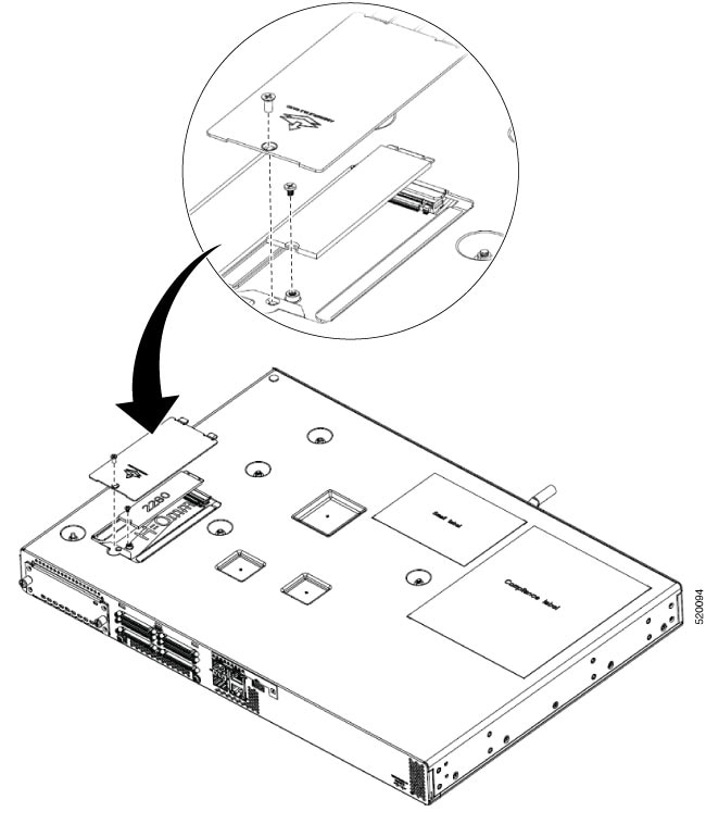
The M.2 storage module is a hardware that is 22mm wide and 80mm long. This hardware comes with different storage capacities.

To install the M.2 storage module, perform these steps:

Procedure

  Command or Action Purpose

Step 1

Remove the SSD panel from the bottom side of chassis by unfastening the screws and keep the screws aside.

Step 2

Plug in the new M.2 storage module and secure it with the screws.

Do not remove the main cover of the chassis as there are no user replaceable parts inside.

Warning


No serviceable parts inside. To avoid risk of electric shock, do not open. Statement 1073

Step 3

Install the SSD panel back with the screws.

LTE Dongle Support on Cisco 1100 Series Terminal Gateway

Install a Micro-SIM Card into a USB LTE Dongle

This section describes how to insert a micro-SIM card into a USB LTE dongle.

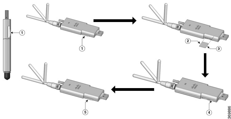
Figure 1. Micro-SIM Card Slot with Dust Cover

SUMMARY STEPS

  1. To insert a micro-SIM card into a USB LTE dongle, do these steps:
  2. To remove a micro-SIM card into a USB LTE dongle, do these steps:

DETAILED STEPS


Step 1

To insert a micro-SIM card into a USB LTE dongle, do these steps:

  1. Tap open the micro-SIM protective cap on the USB dongle, gently insert the micro-SIM card with its edge oriented as shown in the figure until the SIM is seated in the socket.

  2. Tap close the micro-SIM protective cap on the USB to close the slot.

Step 2

To remove a micro-SIM card into a USB LTE dongle, do these steps:

  1. Tap open the dust cover, and then gently push the micro-SIM card to eject the card from the SIM slot.

  2. Tap close the micro-SIM protective cap on the USB to close the slot.

Note


The antenna orientation may need to be adjusted for optimal performance.


Connecting the USB LTE Dongle to the Terminal Server

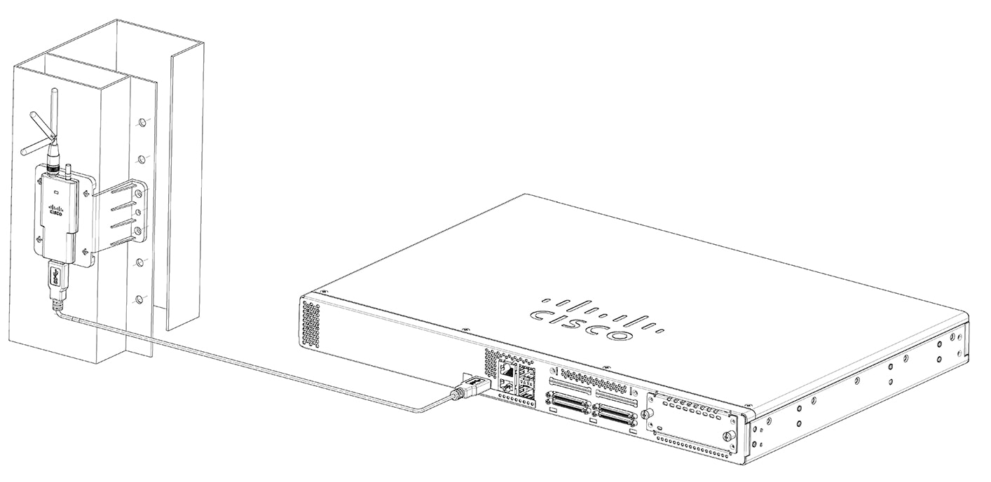
This section provides the necessary steps to establish a successful connection between the USB LTE Dongle and the Terminal server.

SUMMARY STEPS

  1. Pick up the R-Brackets (700-121611-01) Place and fix the bracket at an appropriate location on the rack using two screws.
  2. Tighten the screw, the recommended torque is 10-12 in-lb.
  3. Assemble dongle, USB, cable and antenna together in advance.
  4. Pick up the wall-mounting bracket (700-121609-01) and 2 SCREWS (48-0580-01).
  5. Align and fasten the screws.
  6. Plug the USB cable to the USB port on the chassis to complete the mounting procedure.

DETAILED STEPS


Step 1

Pick up the R-Brackets (700-121611-01) Place and fix the bracket at an appropriate location on the rack using two screws.

Step 2

Tighten the screw, the recommended torque is 10-12 in-lb.

Step 3

Assemble dongle, USB, cable and antenna together in advance.

Step 4

Pick up the wall-mounting bracket (700-121609-01) and 2 SCREWS (48-0580-01).

Step 5

Align and fasten the screws.

Step 6

Plug the USB cable to the USB port on the chassis to complete the mounting procedure.


Remove and replace the battery

These instructions are provided in order to comply with the EU Battery Replaceability Requirement.

  • This product was not specifically designed for battery replacement in the field.

  • It is recommended that, whenever possible, follow the standard repair or return process for battery issues.


Caution


Always wear an ESD-preventive wrist strap and ensure that it makes good contact with your skin when you remove or install the internal modules. Connect the equipment end of the wrist strap to the metal part of the chassis.


Remove the battery

Perform this procedure when the battery requires replacement or maintenance on supported hardware.


Note


Follow proper electrostatic discharge (ESD) precautions before handling the battery or device.

Wear an ESD-preventive wrist strap, ensuring that it makes good skin contact. Connect the clip to an unpainted surface of the chassis frame to channel unwanted ESD voltages safely to ground. To guard against ESD damage and shocks, the wrist strap and cord must operate effectively.


Warning


Statement 1015—Battery Handling

To reduce risk of fire, explosion or leakage of flammable liquid or gas:

  • Replace the battery only with the same or equivalent type recommended by the manufacturer.

  • Do not dismantle, crush, puncture, use sharp tool to remove, short external contacts, or dispose of in fire.

  • Do not use if battery is warped or swollen.


Procedure


Step 1

Before you perform any module replacement, read the Safety Warnings section and disconnect the power supplies.

Step 2

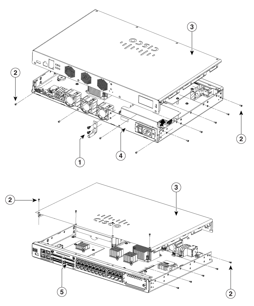
To access the battery, first remove the ground lug and the screws. Remove all the 18 screws from the cover and remove the cover.

Figure 2. Remove the cover

1

Ground lug and screws

2

Chassis screws

3

Chassis cover

4

Power/ fan side of chassis

5

I/O side of chassis

Step 3

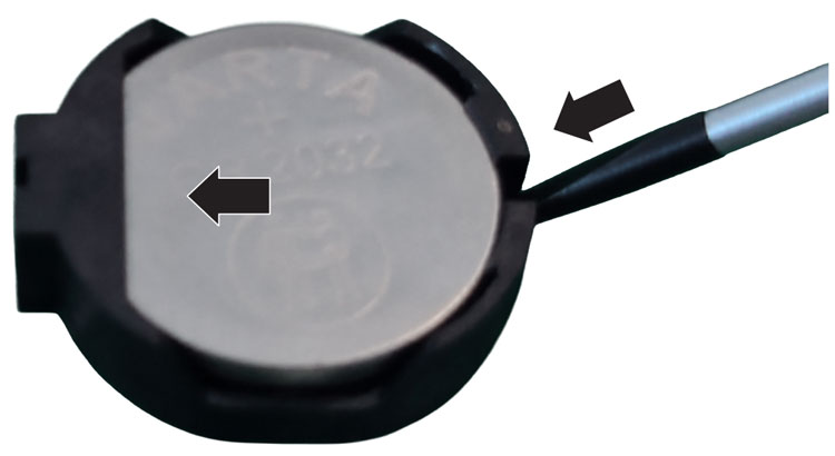
Insert a thin tipped screw-driver in the gap of the holder and gently push the battery away from the screw-driver tip.

Step 4

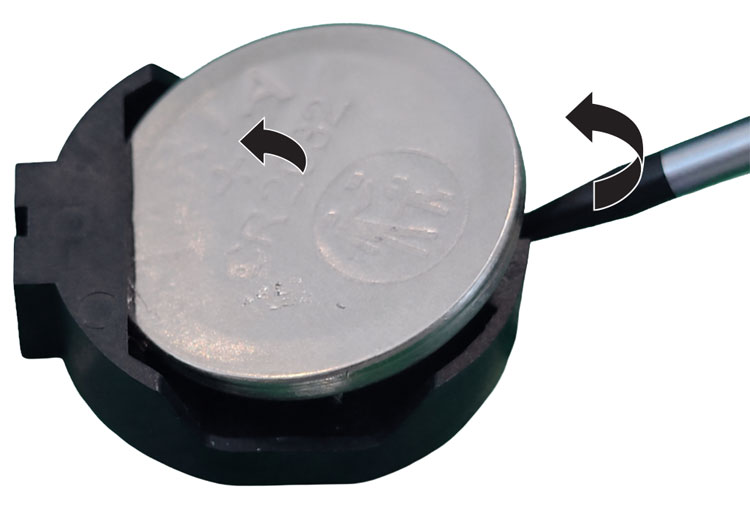
Rotate the screw tip to release the battery from the holder.


Replace the battery

Replace the battery in the chassis following the safety procedures to ensure proper device functionality.

Note


Follow proper electrostatic discharge (ESD) precautions before handling the battery or device.


Before you begin

  • The battery is a CR2032 type. Batteries should only be replaced with the same or an equivalent type recommended by the manufacturer.

    • JHT CR2032

Procedure


Step 1

Read the Safety Warnings instructions and disconnect the power supplies before you perform any module replacement.

Step 2

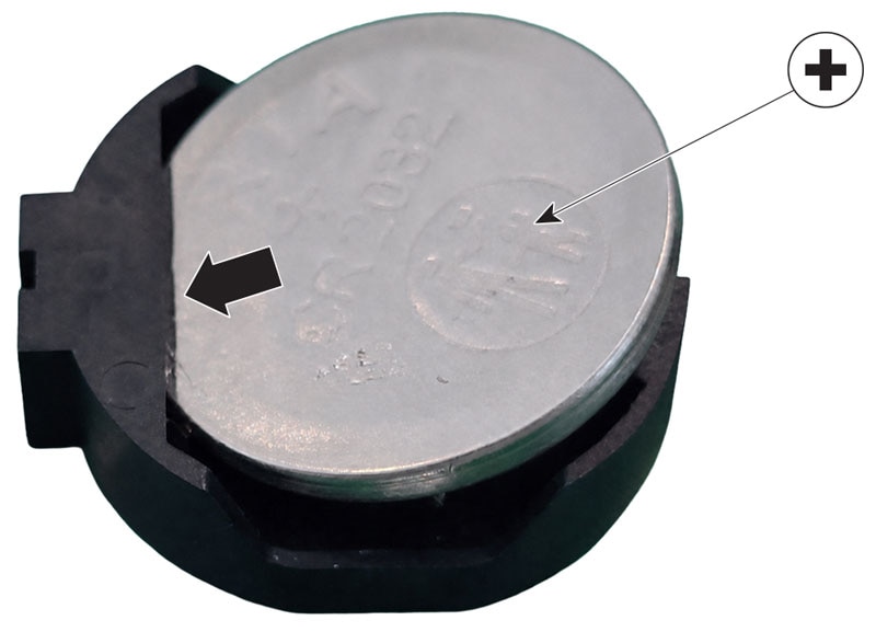
Orient the battery with positive polarity as shown.

Step 3

Insert the battery into the holder so that one edge is under the overhang.

Step 4

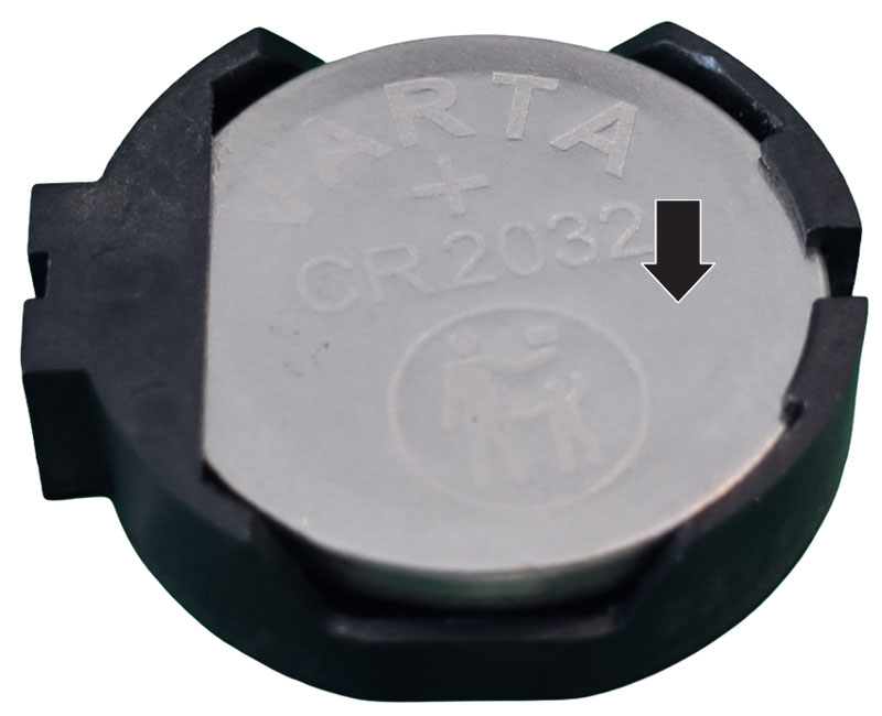
Press the opposite edge down so it snaps into the holder.

Step 5

Replace the cover and secure the screws.