Validated Profile: Cloud Managed Retail Vertical
Available Languages
Bias-Free Language
The documentation set for this product strives to use bias-free language. For the purposes of this documentation set, bias-free is defined as language that does not imply discrimination based on age, disability, gender, racial identity, ethnic identity, sexual orientation, socioeconomic status, and intersectionality. Exceptions may be present in the documentation due to language that is hardcoded in the user interfaces of the product software, language used based on RFP documentation, or language that is used by a referenced third-party product. Learn more about how Cisco is using Inclusive Language.
- US/Canada 800-553-2447
- Worldwide Support Phone Numbers
- All Tools
 Feedback
 Feedback
Note: For the Retail (Non-Fabric) Vertical Cisco Validated Profile, see Validated Profile: Retail (Non-Fabric) Vertical.
Document purpose and usage
The audience for this document includes network design engineers and network operations personnel who wish to design, deploy, and operate cloud-managed campus and branch networks. Branch networks can be deployed using Cisco's prescriptive publicly available Terraform-based code.
This guide focuses on how to design and deploy a cloud-managed retail network consisting of a corporate campus and distributed retail stores within an enterprise network. It covers deployment using the Meraki Dashboard and Cisco Network as Code (NaC) for day-zero and day-n operations, as well as monitoring the overall health of both campus and store networks. Customers from other verticals such as financial services with similar design requirements will also benefit from the contents of this document.
Solution overview
This document provides guidance and serves as a validation reference for a comprehensive Cloud Managed Retail enterprise network deployment leveraging Cisco's Cloud Managed Campus and Unified Branch architecture with cloud-managed infrastructure and Branch as Code (BaC) principles.
Modern retail networks encompass hundreds of stores distributed across diverse geographic regions, each requiring consistent, secure, and high-performing network infrastructure. Retail operations demand a unified management approach that can streamline network operations, reduce operational complexity, and accelerate deployment timelines while maintaining the highest levels of security and compliance. Each store location requires self-contained network services with reliable connectivity to support payment processing, inventory management, customer experience applications, and business-critical operations. Traditional branch networking approaches with disparate management systems create operational silos, increase complexity, and limit business agility.
Cloud managed retail architecture
Modern retail operations demand agile, secure, and scalable network infrastructure that can adapt to rapidly changing business needs. The complexities inherent in retail networks—spanning hundreds or thousands of locations, diverse device ecosystems, strict compliance requirements, and customer-facing services—require a fundamentally different approach to network management.
Cisco Meraki's cloud-managed platform transforms retail networking by eliminating the operational complexity traditionally associated with multi-site deployments while delivering enterprise-grade security, visibility, and performance. This document outlines how Meraki cloud-first architecture addresses the challenges facing retail organizations today.
Cloud-native management platform
Centralized cloud management provides zero-touch deployment with automatic device discovery, cloud-based provisioning, and template-driven configurations enabling rapid store openings and seasonal location deployments. The unified management interface delivers single pane of glass control for headquarters campuses, distribution centers, and branch store locations with role-based access controls, while automated lifecycle management handles firmware updates, security patches, and configuration changes with scheduling capabilities across the entire retail network estate.
AI-driven operations leverage Cisco AIOps with comprehensive telemetry data and ThousandEyes integration to deliver end-to-end visibility and actionable insights. Proactive issue resolution uses AI-driven analytics for rapid incident resolution that traditional manual workflows cannot achieve, while predictive analytics employ machine learning algorithms to identify potential issues before they impact business operations.
Comprehensive network services stack
The integrated security framework addresses retail-specific requirements through a comprehensive approach that prioritizes data protection and operational continuity. The Next-Generation Firewall Integration provides Unified Threat Management with integrated intrusion prevention, malware protection, and content filtering built directly into the branch router platform. This consolidation enables PCI DSS Compliance through automated network segmentation and security policies specifically designed for payment card data protection, while implementing Zero Trust Network Access principles with identity-based access controls and continuous verification for all network resources.
Advanced Threat Protection capabilities deliver real-time security intelligence through cloud-delivered threat intelligence with automatic policy updates, ensuring the latest threat signatures are immediately available across all retail locations. Behavioral analytics powered by AI algorithms detect anomalous network behavior and potential security threats before they impact operations. When security events occur, incident response automation provides immediate containment and remediation capabilities, minimizing business disruption and maintaining customer trust.
SD-WAN and connectivity services
Application-aware Meraki SD-WAN provides intelligent path selection with automatic traffic steering based on application requirements, link quality, and business policies, while direct internet access enables local internet breakout for cloud applications, reducing latency and improving customer experience. Application performance optimization delivers WAN optimization and quality of service prioritization for business-critical retail applications including POS systems and inventory management.
Connectivity resilience ensures business continuity through multipath connectivity combining primary broadband with cellular LTE or 5G backup, maintaining POS system connectivity and store operations during outages. Automatic failover capabilities provide seamless transitions between connection types, while dynamic bandwidth allocation manages traffic based on business priorities and time-of-day requirements, ensuring optimal performance during peak shopping periods.
Intent-based networking for retail
Retail organizations can set their overall goals—such as desired features, network performance, security rules, and compliance requirements—and the Meraki Dashboard automatically converts these goals into specific device settings, keeping them updated across all store locations. Instead of configuring each switch, access point, and security device individually, administrators focus on business needs like separating payment traffic, prioritizing point-of-sale applications, or providing branded guest Wi-Fi. The Dashboard manages the network behind the scenes to ensure these goals are consistently met across hundreds or thousands of locations. This method changes retail IT by shifting from managing individual devices to managing all branch services together as one unified system aligned with business objectives.
Retail-specific operational capabilities
Meraki Dashboard automates PCI DSS compliance through policy-driven network segmentation and one-click audit reports, while dedicated POS segments ensure payment security. Native IoT support with automatic device discovery enables seamless integration of sensors, beacons, and smart shelving through comprehensive APIs connecting inventory management and business intelligence platforms. MR access points (AP)s and MV cameras deliver customer behavioral analytics—shopping patterns, traffic flows, and dwell times—directly through the Dashboard, all of which can exported into external system through API integration.
Operational excellence and strategic agility
Meraki Dashboard enables rapid retail expansion through configuration templates that deploy consistent network policies across new locations instantly. Zero-touch provisioning allows stores to become operational within hours—ship devices, plug in, and automatically receive configurations from the cloud. Centralized management eliminates the need for specialized networking staff at each location, with remote troubleshooting and diagnostics resolving most issues without field visits. BaC further enhances efficiency by enabling infrastructure-as-code workflows, version control, and automated testing of network configurations before deployment. Built-in change tracking and audit logs provide complete visibility, while role-based administration supports franchise models with delegated access.
The Cloud Managed Retail Profile with Unified Branch architecture represents the evolution from traditional branch networking to a comprehensive, software-defined retail infrastructure platform that aligns network capabilities directly with business objectives and operational requirements.
This combination of Meraki’s cloud dashboard and NaC practices forms the foundation of a modern small branch design tailored to the fast-moving retail industry.
BaC implementation
BaC uses DevOps NaC ideas to make managing retail branch networks easier. Instead of setting up each device by hand, network administrators write simple, clear instructions in pre-made YAML templates and use Terraform tools. These templates include Cisco’s trusted best practices, so the system automatically sets up and manages all branch services consistently and correctly across all locations. This approach saves time, reduces errors, and ensures every branch follows the same high standards.
This approach uses Git-based version control, automated testing, and CI/CD pipelines to quickly set up new stores in minutes instead of days. It ensures consistent network standards across different types of retail businesses and smoothly connects with existing retail IT systems like point-of-sale and inventory management platforms. This automation speeds deployment, reduces errors, and keeps everything working together efficiently. The framework offers ready-made templates tailored for different retail store sizes, from small shops to flagship locations. It includes specific configurations for various functions such as PCI DSS-compliant point-of-sale (POS) networks, guest Wi-Fi with analytics, and IoT device profiles. It also features thorough change management with automatic rollback options. This approach changes retail network operations by replacing manual, error-prone device setup with automated, scalable service deployment, ensuring the entire retail network runs with optimal performance, security, and compliance.
Solution components
There are three fundamental pillars of the Cloud Managed enterprise. These pillars are the Cisco platforms and dashboard, the BaC toolkit and the Cisco ISE.
Cisco platforms and Meraki Dashboard
The Cisco Cloud Managed enterprise uses a cloud-based dashboard as the main control center for the entire branch network. This easy-to-use interface acts like a network controller, handling and analyzing all important data. It gives IT teams full, real-time insight into the health, performance, and security of every part of the network. From this dashboard, IT can configure devices, enforce policies, monitor user experience, detect problems, and automate responses to keep the network running smoothly and securely.
The platform integrates four core service areas under this unified management approach.
Cisco Secure Routing combines traditional routing functions with built-in Next-Generation Firewall features in one device. It offers network segmentation to separate different types of traffic, policies based on service-level agreements (SLAs) to prioritize important applications, secure SD-WAN tunnels for encrypted connections, and strong protection against threats. This integration helps create a secure, efficient, and well-managed network for branch offices and other locations.
The Secure Wired Access component uses LAN switching with network segmentation through VLANs, port security controls, and 802.1X authentication to ensure only authorized devices can access the network.
Secure Wireless Access delivers enterprise-grade Wi-Fi 7 technology with strong authentication mechanisms and multiple SSIDs that create distinct wireless networks with tailored security policies for different user groups like employees and guests.
Application Optimization and Visibility ensures business-critical applications receive priority treatment across the network. Quality of Service (QoS) policies guarantee consistent performance for voice, video, and essential business applications, while deep packet inspection provides granular visibility into application usage patterns. Cisco ThousandEyes integration delivers end-to-end application performance monitoring from branch locations through the WAN to cloud applications and data centers.
All these components work together through the centralized dashboard, enabling IT teams to configure devices, enforce policies, monitor user experience, detect anomalies, and orchestrate automated responses from a single pane of glass.
This unified approach transforms complex operational data into actionable intelligence, enabling proactive network management and rapid issue resolution while eliminating the fragmentation typically associated with multi-vendor branch environments.
BaC toolkit
The BaC toolkit empowers retail organizations to deploy and manage network infrastructure using proven DevOps principles and Infrastructure as Code methodologies. The toolkit includes a dedicated Terraform provider that serves as the programmatic interface for translating high-level business intent into device-specific configurations across Meraki's entire product portfolio. Pre-validated YAML templates provide retail-specific deployment patterns for different store sizes and operational requirements, embedding Cisco proven best practices for POS network segmentation, guest Wi-Fi configurations, IoT device policies, and compliance frameworks. The toolkit enables version-controlled network configurations through Git integration, automated testing pipelines that validate configurations before deployment, and comprehensive change management workflows with approval processes and automated rollback capabilities. This approach transforms traditional manual network deployment from days to minutes while ensuring consistency, reducing human error, and providing complete audit trails for regulatory compliance across hundreds of retail locations. BaC currently supports small branch designs for the first release. Medium and large branches are planned for the next release. Branch security is decentralized with security being configured an individual branches.
Cisco ISE
ISE integration provides centralized RADIUS authentication and policy enforcement across all retail locations, enabling granular access control for employees, contractors, guests, and IoT devices. Cisco ISE delivers dynamic policy assignment based on user identity, device type, and location context, automatically placing POS terminals in secure payment networks while directing guest devices to isolated internet-only segments. The platform supports certificate-based authentication for corporate devices, Active Directory integration for employee access, and device profiling for automatic IoT device identification and policy assignment. Comprehensive compliance reporting capabilities provide detailed audit trails for regulatory requirements, while real-time threat containment enables immediate network quarantine of compromised devices, ensuring robust security posture across the distributed retail environment.
Cloud Managed Retail Profile summary
This table highlights the key focus areas of the Cloud Managed Retail solution profile.
| Key Deployment Area |
Feature |
| Greenfield Corporate campus deployment |
Bring up a new corporate campus managed by Meraki Cloud Dashboard |
| Data Center Connectivity for common enterprise service access |
Campus Core layer BGP/OSPF configuration towards Datacenter |
| Meraki SD-WAN deployment |
Bring up of Meraki SD-WAN to connect the Corporate Campus, Datacenters and the Retail Stores WAN Resilience |
| Retail Store/branch Deployment |
Deploy Store network using BaC infrastructure Security Framework for Wired and Wireless Guest Access Firewall Polices |
| Seasonal Scalability and Rapid deployment of retail stores |
Deploying new stores/branches with BaC |
| End-to-End Application Performance Monitoring |
Thousand Eyes Branch/Store Health Dashboards |
| Organization-wide Image Management |
Zero-Touch Firmware Management |
Hardware and software specifications
The solution is validated with the hardware and software listed in this table.
For the complete list of catalysts supported for Cloud management, see Enable Cloud Management for Catalyst Switches with Device Configuration.
| Role |
Model Name |
Software Version |
| Cloud Managed Catalyst |
C9500-32C, C9300-24P, C9300-48P, C9300-48T, C9300X-24Y, C9200L-24P-4G |
17.18.2 |
| Meraki MX |
MX85, MX95, MX68 |
19.1.1 |
| Wireless Access Points |
CW9172, CW9176, MR42, MR45, MR56 |
31.1 |
| Meraki Vision Camera |
MV12W |
|
| Identity Management, RADIUS Server |
SNS-3695-K9 |
2.7 Patch 7 |
Cloud Managed Retail solution topology
Solution use cases
| Key Deployment Area |
Feature |
| Greenfield Corporate campus deployment |
Bring up a new corporate campus managed by Meraki Cloud Dashboard Catalyst switch onboarding in cloud managed mode Deploy Core, Distribution and Access layers in campus Campus Routing Architecture and Design Redundancy and High Availability |
| Data Center Connectivity for common enterprise service access |
Campus Core layer BGP configuration towards Datacenter |
| Corporate Wireless deployment |
Onboarding APs to Meraki Dashboard Wi-Fi deployment for corporate headquarters Enterprise-grade wireless with advanced QoS and security Guest wireless with captive-portals |
| Meraki SD-WAN deployment |
Campus-to-Branch Communication AutoVPN mesh between headquarters and stores High Availability and WAN Resilience – WAN Uplink selection and Load balancing at MX (Hubs and Spokes) |
| Retail Store/branch Deployment |
BaC – Deployment Guidelines Deploy Branch/Store networks using BaC infrastructure |
| Security Framework- Zero-trust network access principles Secure Wireless Connectivity WPA3-Enterprise (POS Uses Wi-Fi) Access Policies for Wired POS Threat protection and content filtering (AMP, IPS/IDS) Firewall Policies to secure POS traffic – NGFW at MX Direct Internet Access (Local Internet Breakout)/VPN Exclusion Rules High Availability and WAN Resilience SLA based WAN Performance Policies – Uplink selection and Load balancing Application Monitoring and Alerting |
|
| Guest Wi-Fi and Customer Footfall Analytics Guest-Wi-Fi with Captive Portals Firewall Rules for Guest Network Content Filtering for Guests Location Analytics |
|
| Seasonal Scalability and Rapid branch/store deployment |
Deploying new stores/branches with BaC templates |
| End-to-End Application Performance Monitoring |
Thousand Eyes implemented at Branch MX for Network Performance Visibility |
| Organization-wide Image Management |
Zero-Touch Firmware Management for entire enterprise |
Scale
Solution test verified the scale numbers listed in this table.
| Category |
Value |
| Number of branches |
10 |
| Number of devices per branch |
10 |
| Number of Access Points |
400 |
| Number of endpoints |
4500 |
Solution keynotes
Prerequisites for Meraki Dashboard organization and device inventory
Before proceeding with the campus and branch deployment configurations detailed in the following sections, customers must complete the foundational setup of their Meraki Dashboard organization and claim all network devices into inventory. This prerequisite ensures a streamlined deployment experience and enables the centralized management capabilities that form the foundation of this Cloud Managed Retail Profile.
Procedure 1. Required pre-deployment steps:
Step 1. Meraki Dashboard Organization Creation: Customers must establish a Meraki Dashboard organization account that will serve as the central management platform for the entire retail network infrastructure. This organization provides the administrative framework for managing campus Catalyst switches, branch Meraki appliances, wireless APs, and all associated policies and configurations across the retail enterprise.
Step 2. Corporate Network Creation: Within the Meraki Dashboard organization, create a dedicated network construct for the corporate campus deployment. Navigate to Organization > Configure > Create Network and establish a network named according to your corporate naming conventions (for example, "Corporate-HQ-Campus" or "Retail-Headquarters"). Select the appropriate network type as "Switch" to enable Catalyst switch management capabilities. This network construct serves as the logical container for all campus infrastructure devices and their associated configurations, policies, and monitoring data.
Step 3. Device Inventory Claiming: All network devices including Catalyst 9500 core switches, Catalyst 9300 distribution and access switches, MX security appliances, MS switches, and MR APs must be claimed into the Meraki Dashboard inventory using their unique serial numbers. Access Organization > Configure > Inventory and add devices by entering serial numbers or uploading a CSV file for bulk claiming. This claiming process establishes device ownership, enables cloud management capabilities, and prepares devices for network assignment and configuration deployment.
Step 4. Licensing Validation: Verify that appropriate Meraki licenses (Enterprise, Advanced Security, SD-WAN Plus) are applied to all claimed devices and that license expiration dates align with operational requirements. Check license status in Organization > Configure > License Info to ensure all devices have active subscriptions. Valid licensing is essential for accessing advanced features including BaC capabilities, ThousandEyes integration, and enterprise security functions.
Step 5. Network Administrator Access: Ensure that appropriate administrative accounts are created with role-based access controls aligned to organizational structure. Navigate to Organization > Configure > Administrators to create accounts with appropriate permission levels including full administrators for corporate IT teams, read-only access for operations staff, and delegated administration rights for franchise or regional managers as applicable.
Step 6. Network Device Assignment: After devices are claimed into inventory, assign them to the appropriate network constructs. Campus Catalyst switches should be assigned to the corporate campus network, while branch devices will be assigned to their respective store networks. Navigate to Organization > Inventory, select devices, and use the "Add to network" function to complete the assignment process.
Step 7. Catalyst Switch Onboarding: Onboard Catalyst 9500 and 9300 switches to the Meraki Dashboard in cloud-managed mode following Cisco's official onboarding procedures. This process involves converting the switches from traditional IOS-XE management to cloud-managed operation, establishing secure communication with Meraki cloud infrastructure, and registering devices within the corporate network construct. For detailed step-by-step guidance on onboarding cloud-managed Catalyst switches, refer to the official Cisco documentation: Onboarding Cloud-Managed Catalyst switches to the Meraki Dashboard. The onboarding process includes initial device discovery, cloud redirect configuration, secure certificate exchange, and validation of cloud management connectivity.
With these prerequisites completed, customers can proceed confidently to the deployment sections that follow, leveraging the cloud-managed infrastructure foundation to implement the campus and branch network architectures detailed in this Cisco Validated Profile.
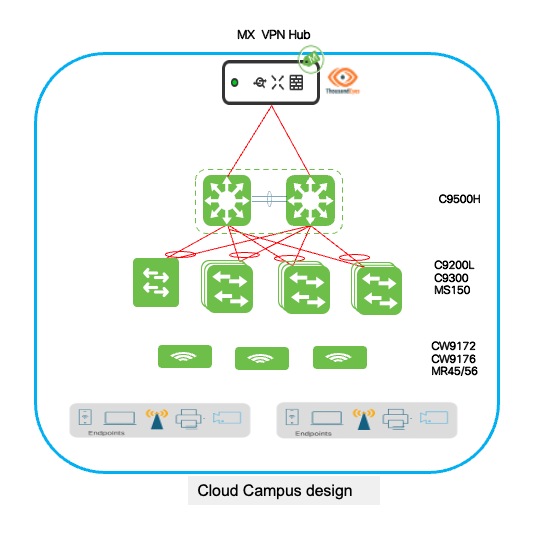
Greenfield corporate campus deployment
The greenfield corporate campus deployment leverages Cisco Catalyst 9500-SVL at the core or distribution with Catalyst 9300/9200L switches at access layers, all managed through Meraki Cloud Dashboard for unified visibility. This cloud-managed architecture supports centralized retail operations including enterprise applications, inventory management, and corporate services for hundreds of distributed stores, with seamless Catalyst device onboarding through zero-touch provisioning. Enterprise clients receive 802.1X authentication integrated with Active Directory, while retail-specific devices like mobile scanners and warehouse terminals are automatically profiled and assigned to appropriate network segments, and guest access for vendors and franchise partners uses captive portal authentication with isolated network segments. The 9500-SVL core pairs provide high-availability with distributed forwarding for business continuity, while access layers implement EtherChannel link aggregation and StackWise stacking for redundant uplinks and simplified management, eliminating single points of failure at every tier. The Meraki Dashboard delivers centralized policy management, real-time monitoring, and automated compliance reporting, enabling consistent security postures across diverse client populations. This architecture scales from regional headquarters to enterprise-scale operations managing thousands of store locations, positioning the campus as the central hub for network operations, policy distribution, and centralized authentication, while BaC principles extend consistent configurations and security frameworks to all store locations.
Corporate Retail Campus diagram
Catalyst switch cloud onboarding process
Cisco Catalyst 9000 series switches operating in cloud-managed mode through Meraki Dashboard require a streamlined onboarding process that converts traditional IOS-XE managed switches to cloud-managed operation, establishing secure connectivity to Meraki cloud infrastructure and enabling centralized configuration and monitoring capabilities. The onboarding workflow involves initial console access to the switch for basic connectivity configuration, network parameter setup ensuring the switch can reach Meraki cloud services through HTTPS, and cloud redirect activation that transitions the switch from local CLI management to cloud-based dashboard control. During onboarding, the switch downloads cloud management software, establishes secure encrypted communications with Meraki infrastructure using TLS, validates licensing and organizational assignment, and synchronizes its configuration with the assigned network in the dashboard, after which all subsequent management operations occur through the intuitive web-based interface eliminating the need for direct CLI access or complex configuration file management.
Detailed onboarding prerequisites and procedures
The comprehensive step-by-step onboarding guide is available in Cisco's official documentation at: Onboarding Cloud-Managed Catalyst switches to the Meraki Dashboard. This documentation provides detailed instructions covering initial switch preparation including console connectivity requirements and default credential access, network connectivity configuration specifying management VLAN setup and IP address assignment methods (DHCP or static), internet connectivity validation ensuring switches can reach required Meraki cloud endpoints (*.meraki.com, *.cisco.com), cloud management mode activation through the enable cloud-managed command transitioning operational control to the dashboard, claiming procedures associating physical switches with organizational inventory using serial numbers or order numbers, and troubleshooting guidance addressing common onboarding challenges including connectivity failures, certificate validation issues, or licensing problems that may prevent successful cloud registration.
Organizations deploying multiple Catalyst switches across retail campus environments should review the complete onboarding documentation before beginning deployment activities, ensuring IT staff understand the process flow, required network prerequisites, and validation procedures that confirm successful cloud connectivity before proceeding to large-scale rollouts across core, distribution, and access layers.
Post-onboarding configuration and management connectivity
After Catalyst switches complete the cloud onboarding process and are successfully added to the network in Meraki Dashboard, the switches automatically initiate a firmware synchronization process, upgrading to the latest stable firmware version configured at the organizational level, ensuring consistency across all switches in the deployment without manual intervention. During initial connectivity establishment, switches acquire management IP addresses dynamically through DHCP from any available VLAN on upstream network devices, enabling immediate cloud communication and dashboard registration even before administrators configure specific management network parameters. This bootstrap connectivity allows switches to reach Meraki cloud services, download configurations, and appear as online devices in the dashboard, enabling true zero-touch deployment where switches can be shipped directly to remote locations, powered on by non-technical staff, and automatically provision themselves without requiring on-site IT expertise or manual configuration, providing operational flexibility during deployment phases when final network architecture may not yet be fully implemented. After verifying successful cloud connectivity and initial registration, configure the dedicated management VLAN for the network.
Procedure 2. To configure the dedicated management VLAN for the network:
Step 1. Navigate to Switch > Configure > Switch Settings > Management VLAN.
Step 2. Specify the VLAN ID designated for network management.
After you set up the management VLAN for the network, all switches in that network will automatically give up their current DHCP-assigned IP addresses and ask for new ones from the management VLAN you defined. This change moves their management connections to a specific, standard network segment used for managing, monitoring, and accessing the network infrastructure. This helps keep management traffic separate and organized.
Step 3. (Optional) For environments requiring static IP addressing for management interfaces to support monitoring systems, documentation requirements, or organizational IP address management policies, configure per-switch static management IP addresses through Switch > Switch Details > [Select Switch] > Management Interface.
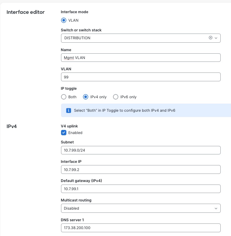
Step 4. (Optional) When transitioning from DHCP to static addressing, create the management IP subnet within the designated management VLAN through Switching > Routing & DHCP.
1. Define the subnet range, default gateway, and DNS servers for management connectivity.
2. Enable the Uplink settings on the management VLAN configuration, designating it as the VLAN capable of reaching external networks including Meraki cloud infrastructure.
This static IP configuration is applied on a per-switch basis, allowing mixed environments where some switches use DHCP for simplified management while critical infrastructure switches (core and distribution layers) use static addressing for precise documentation and integration with enterprise network management systems, SNMP monitoring platforms, and syslog servers requiring predictable, unchanging management IP addresses for consistent connectivity and reporting.
Deploying the Catalyst 9500 StackWise Virtual at core
The core layer deployment implements Cisco Catalyst 9500 series switches in StackWise Virtual Link (SVL) configuration, creating a highly available infrastructure that provides resilient routing, inter-VLAN services, and aggregation capabilities for the retail headquarters campus network. In larger campus deployments, the 9500-SVL pair functions as a dedicated core layer providing high-speed forwarding between distribution blocks, data center connectivity, and WAN edge services, while smaller or medium-sized campuses may deploy the 9500-SVL as a collapsed core/distribution layer combining both hierarchical functions within a single redundant switch pair, reducing infrastructure complexity and cost while maintaining enterprise-grade capabilities.
StackWise Virtual technology virtualizes two physically separate Catalyst 9500 chassis into a single logical switch with unified management, active-active forwarding, and sub-second failover capabilities, eliminating single points of failure while simplifying operational management. The SVL implementation uses dual 100G SVL connections between paired chassis providing high-bandwidth inter-chassis communication, ensuring seamless traffic forwarding and configuration synchronization. Distribution and access layers connect through Multi-Chassis EtherChannel (MEC) configurations treating the SVL pair as a single logical upstream device, enabling active-active traffic distribution and automatic failover without reconvergence delays during chassis or link failures.
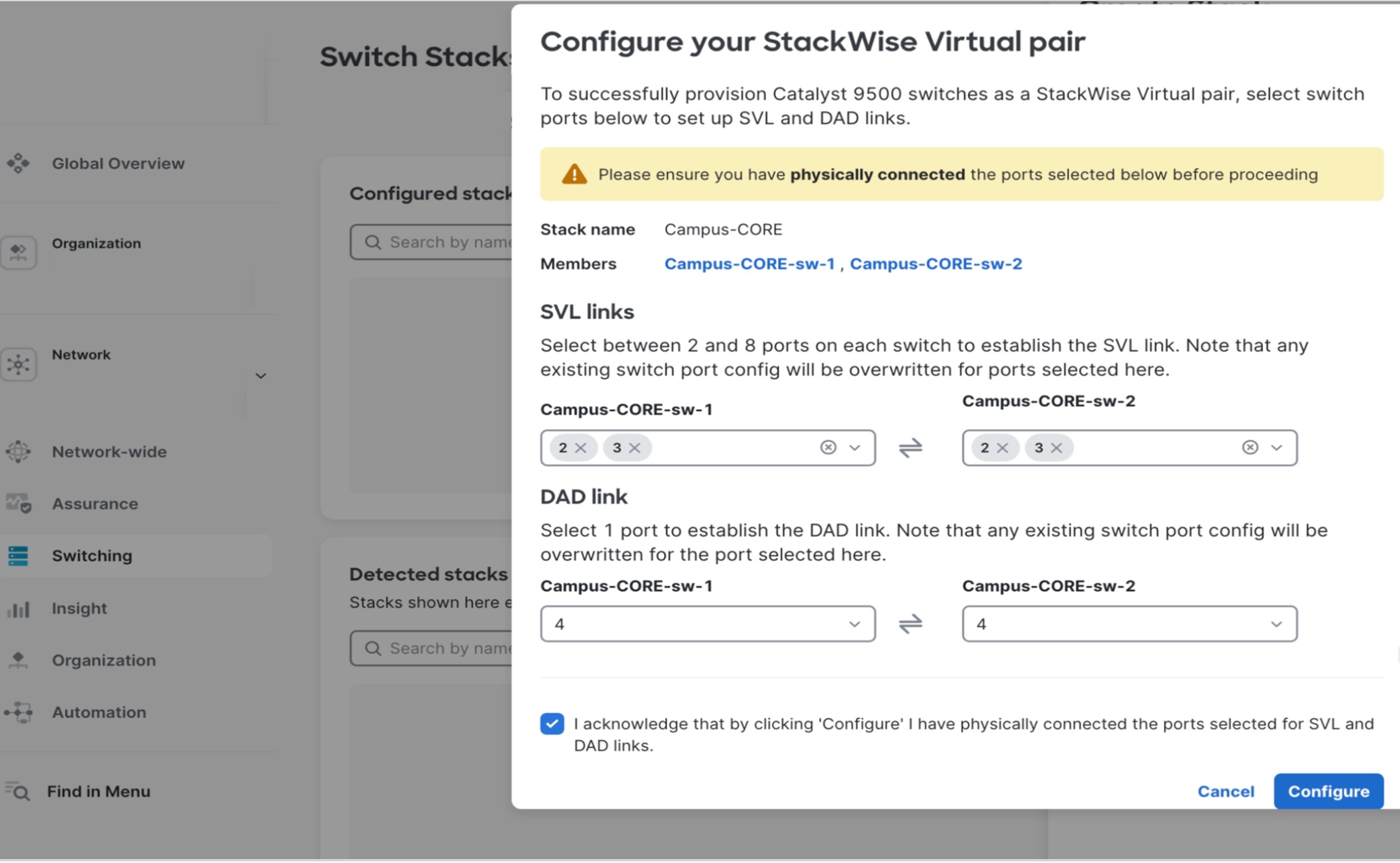
Procedure 3. To onboard a Catalyst 9500 cloud:
Note: Onboarding follows the identical provisioning workflow as the Catalyst 9300 series.
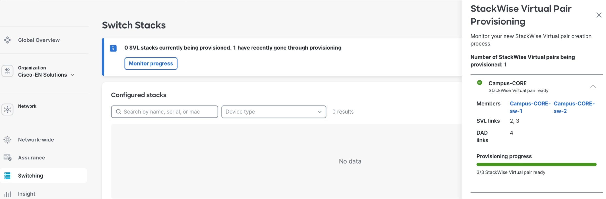
Step 1. After successful onboarding and cloud registration, navigate to Switching > Switch Stacks > Add a Stack within Meraki Dashboard.
The SVL creation wizard prompts for critical configuration parameters including SVL link interface assignments and Dual-Active Detection (DAD) protocol links.
Note: SVL and DAD port selections must match identically on both physical switches for proper redundancy.
Step 2. Select both Catalyst 9500 switches designated for the stack.
Step 3. Specify the SVL member priority.
Step 4. Configure the corresponding physical interfaces.
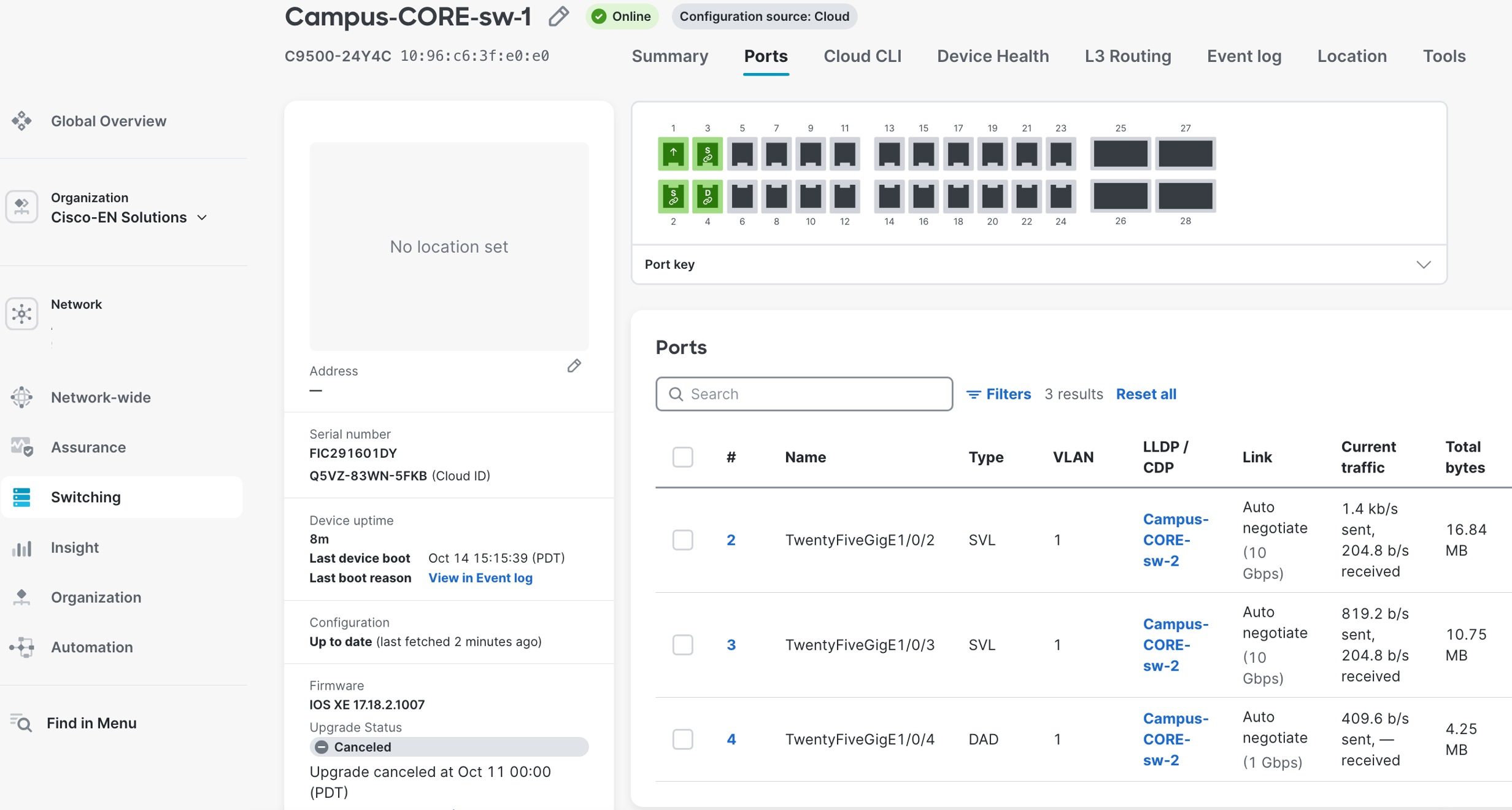
Upon workflow completion, both switches automatically initiate a synchronized reboot to establish the SVL domain and active and standby roles. Real-time SVL formation progress is monitored through the Switch Stacks page, displaying stack member status, synchronization state, and link health.
When operational, the unified SVL pair appears as a single logical switch entity with combined port capacity, automatic failover capabilities, and centralized management through Meraki Dashboard.
Deploying the 9300 and 9200L stacking access layers
The access layer uses Cisco Catalyst 9300 series switches providing enterprise-grade connectivity for end-user devices, printers, IP phones, wireless APs, and IoT infrastructure, delivering the performance, security, and management capabilities required for modern retail campus environments. For cost-sensitive deployments or lower-density areas such as administrative offices, conference rooms, or back-office operations, the Cisco Catalyst 9200L series provides an economical alternative with PoE+ support, fixed uplink configurations, and full Meraki Dashboard integration.
Access layer configuration implements Multi-Chassis EtherChannel (MEC) towards the core 9500-SVL pair providing Layer 2 redundancy and bandwidth aggregation with allowed VLANs trunked across the links, Layer 3 routing with OSPF configured between distribution and core layers for dynamic route advertisement and optimal path selection, routed SVI (Switched Virtual Interface) configuration managed directly from Meraki Dashboard enabling centralized VLAN and IP addressing management.
Access layer switches are physically connected in StackWise or StackWise-480 configurations using dedicated stacking cables between switch rear-panel stacking ports, creating resilient multi-chassis systems before the onboarding process begins. Following the standard cloud onboarding procedure detailed in previous sections, each individual switch in the physical stack is powered on, connects to Meraki cloud infrastructure, and registers with the dashboard using its unique serial number. The Meraki Dashboard automatically detects the physical stacking topology through switch-to-switch stacking protocol exchanges and intelligently forms a logical stack without requiring manual configuration or CLI commands to enable stacking functionality.
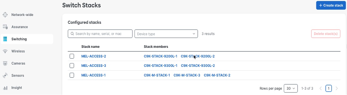
Procedure 4. To view the newly formed stack appearing as a single manageable entity with all member switches displayed:
Step 1. Navigate to Switch > Switch Stacks.
Step 2. Identify their stacking roles (Master/Member) and show stack bandwidth aggregation.
Step 3. Enable unified configuration management where settings applied to the stack automatically propagate to all member switches ensuring consistent behavior across the multi-chassis system.
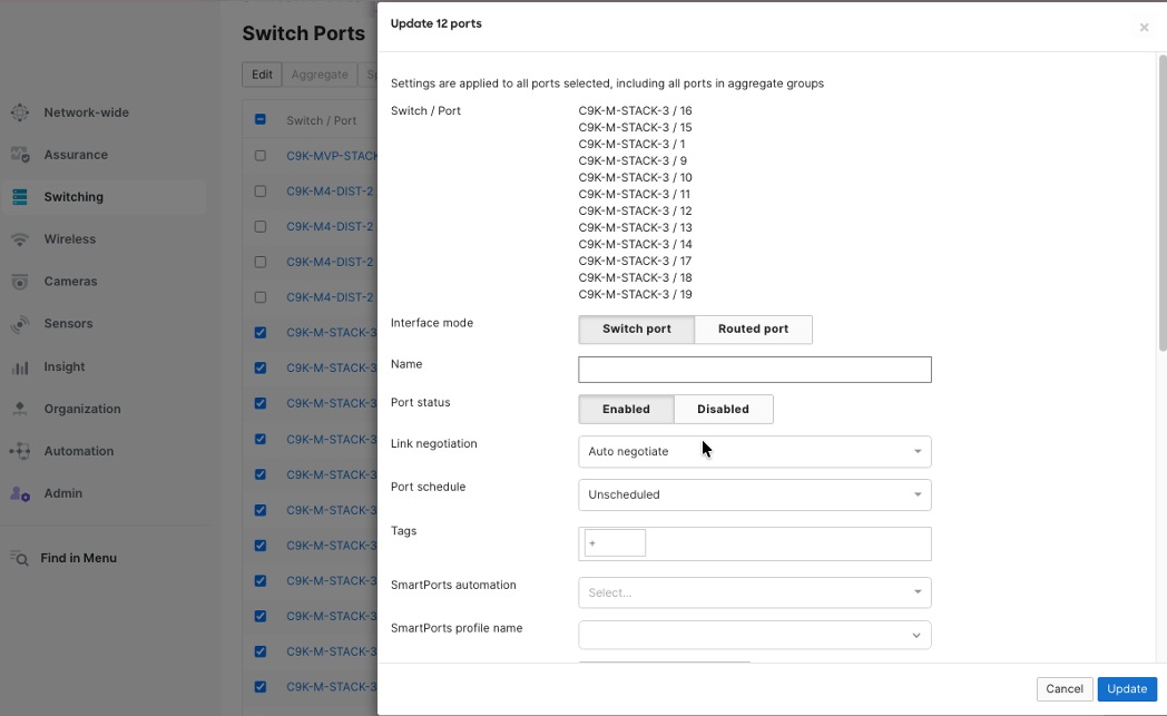
Step 4. Through Meraki Dashboard's centralized switchports configuration interface, access port configuration implements consistent policies across all switches.
Step 5. Enable simultaneous configuration of multiple ports with identical settings including VLAN assignments, PoE parameters, security policies, and quality of service parameters.
The multiple port edit functionality allows network administrators to select dozens or hundreds of ports across single or multiple switches and apply standardized configurations in bulk operations, dramatically reducing deployment time and eliminating configuration inconsistencies across the campus infrastructure.
Procedure 5. To configure multiple switch ports together:
Step 1. Navigate to Switch > Switch Ports in the dashboard.
Step 2. Assign access policies to individual switch ports or groups of ports.
These policies include settings like VLAN membership, authentication rules, traffic shaping, and security controls.
When you apply the same access policy to several ports, any device connected to those ports receives the same network settings, no matter where the port is located on campus.
When setting up network access policies, remember that different device types have their own security and operational needs. For example:
● Employee workstations: Use 802.1X authentication and connect to the corporate VLAN.
● IP phones: Assign them to a voice VLAN with Power over Ethernet (PoE) and Quality of Service (QoS) settings.
● Wireless APs: Use trunk ports to support multiple SSIDs.
● Printers: Place them on a dedicated printer VLAN with restricted internet access.
● IP cameras: Assign them to a separate security VLAN with enhanced PoE (PoE++).
This approach ensures that each device type gets the right network settings and security.
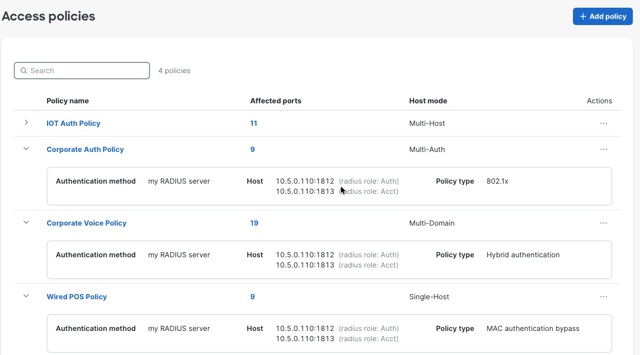
Procedure 6. To create Access Policies for wired devices:
Step 1. Navigate to Switch > Access Policies.
The policies can be configured to use the enterprise centralized Cisco ISE for authorization and accounting.
Step 2. Configure for 802.1x, MAB or Hybrid authentications, for voice and data domains, with granular options for Critical/Failed/Guest VLANs and radius caching.
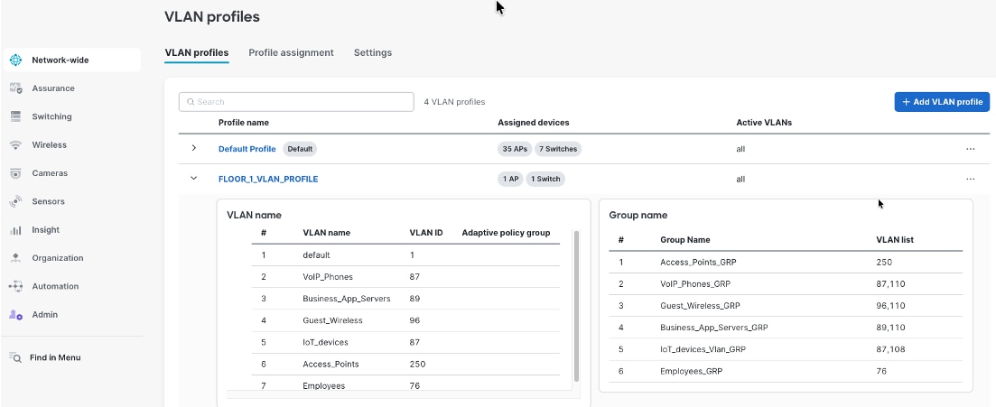
Network VLAN profiles and named VLANs for simplified network management
Meraki Dashboard combines Named VLANs with VLAN Profiles and Cisco ISE integration providing dynamic, identity-based network segmentation for distributed retail campus infrastructure. Named VLANs replace numeric VLAN identifiers with descriptive business-relevant labels like "Corporate-Employees", "POS-Systems", and "Guest-Wi-Fi", making configurations self-documenting and reducing administrator errors. VLAN Profiles enable grouping mechanisms where administrators define different VLAN configurations for different switch groups within the same network, allowing Building A switches to map "Corporate-Employees" to VLAN 10 while Building B switches map the same name to VLAN 40, with each profile containing location-specific VLAN ID assignments for common Named VLANs.
During 802.1X authentication, Cisco ISE validates user credentials and returns a VLAN name (for example, “Corporate-Employees") as a RADIUS attribute during the authorization phase. The authenticating switch receives this VLAN name and consults its assigned VLAN Profile to determine the corresponding VLAN ID for that location—Building A's switch maps "Corporate-Employees" to VLAN 10, while Building B's switch maps the identical VLAN name to VLAN 40—enabling consistent policy enforcement through centralized ISE configuration while accommodating location-specific VLAN numbering schemes across distributed campus infrastructure. This architecture allows ISE administrators to define authorization policies using business-meaningful VLAN names ("assign employees to Corporate-Employees VLAN") without knowing site-specific VLAN IDs, while network administrators maintain flexibility to use different VLAN numbering per building, floor, or functional area based on addressing schemes, legacy infrastructure constraints, or organizational preferences, all managed through Meraki Dashboard's unified interface providing centralized configuration control and consistent policy enforcement across the entire retail headquarters campus.
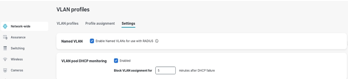
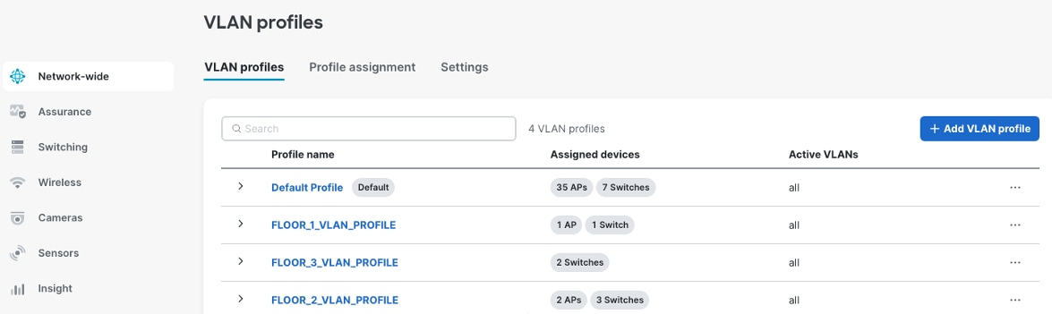
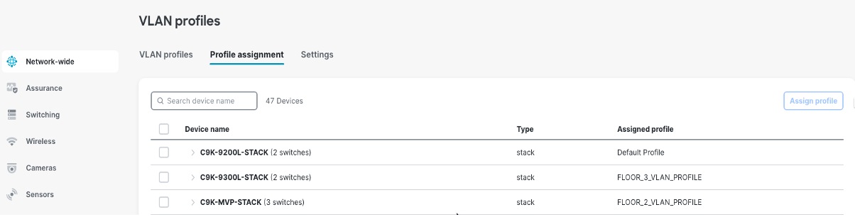
Procedure 7. To create the VLAN profiles:
Step 1. Navigate to Network-wide > VLAN Profiles.
Step 2. Assign the access switches to the respective profiles.
Step 3. To use this feature with Cisco ISE Authentication, enable the option Enable Named VLANs for use with RADIUS.
For Cisco ISE, the authorization policy needs to be defined with the VLAN name as a parameter.
Step 4. Navigate to Cisco ISE > Policy > Policy Elements > Results > Authorization >Authorization Profiles > Profile name > Common Tasks > VLAN name. See this example image.
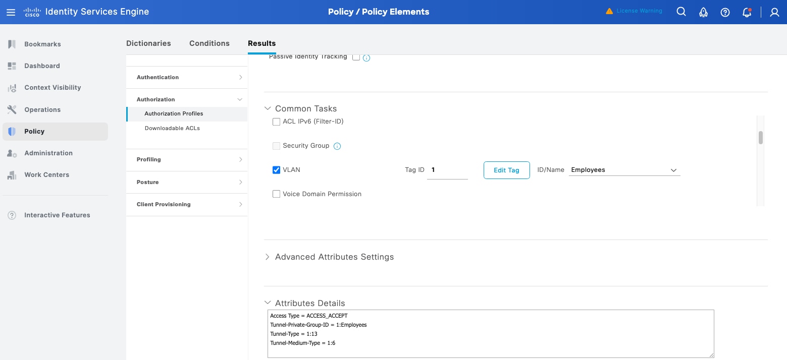
Step 5. Continue to the Meraki dashboard to define the VLAN Profiles and assign the access switches to their respective profiles. See these example images.
Campus routing architecture and design
The Meraki Dashboard software release for cloud-managed Catalyst switches supports flexible routing architectures tailored to campus size, complexity, and operational requirements, enabling retail organizations to implement designs aligned with their specific infrastructure needs and scalability objectives.
For retail environments implementing consolidated architectures, a collapsed core/distribution layer using Cisco Catalyst 9500 switches combines both hierarchical functions within a single high-performance switch pair, with all campus VLANs configured directly on the collapsed core. Retail subnet SVIs can be flexibly placed either on the Catalyst 9500 core switches or on the Meraki MX appliance, depending on design requirements for security inspection, traffic flow optimization, and routing control. The Catalyst 9500 switches establish BGP peering with the local Meraki MX security appliance (deployed in Meraki SD-WAN Hub mode) for WAN connectivity and route learning. These retail subnets are then advertised to the datacenter through iBGP peering between the retail campus MX Hub and the datacenter MX Hub (also deployed in Meraki SD-WAN Hub mode). This centralized architecture provides default gateway services and inter-VLAN routing for the entire retail campus infrastructure, while enabling dynamic routing and full network reachability through the Meraki SD-WAN fabric's iBGP mesh between hub locations.
Access layer switches operate in Layer 2 mode providing VLAN trunking to distribution or core layers and access port connectivity for end-user devices, concentrating routing intelligence at higher network tiers while simplifying access layer configuration and operations.
BGP configuration on Catalyst 9500 using Meraki Dashboard
The Catalyst 9500-SVL core switches establish BGP peering sessions to Meraki MX, configured and managed entirely through the Meraki Dashboard switching interface without requiring CLI access or traditional IOS-XE command-line configuration. Through the Meraki Dashboard BGP configuration interface, administrators define BGP neighbor relationships by specifying the data center fusion switch IP addresses, remote AS numbers, and authentication credentials for secure peering sessions. The dashboard interface automatically validates neighbor configurations, detecting common errors such as AS number mismatches, unreachable neighbor addresses, or missing authentication parameters before committing changes to the network.
Configuring BGP parameters is done through the Meraki Dashboard from the campus network's switching configuration section. AS numbers, neighbor relationships, and route advertisements need configuring. This cloud-managed approach eliminates configuration syntax errors, provides built-in validation of BGP parameters, and enables rapid deployment of routing changes across the campus core infrastructure.
Procedure 8. To create the ASN for your campus:
Step 1. After successful SVL creation at the campus core, navigate to Switching > BGP routing.
Step 2. Add the BGP router.
Step 3. Select the switch.
Step 4. Configure the router-ID.
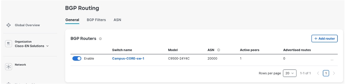
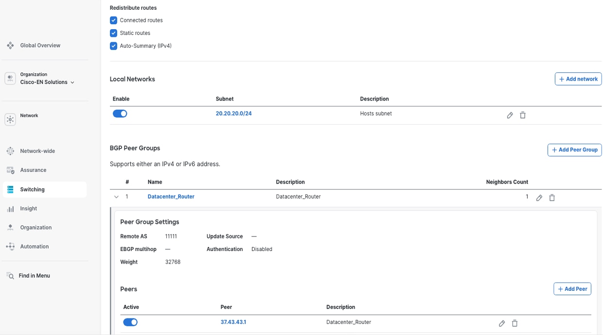
Step 5. To configure further capabilities such as Route Redistribution, Local network advertisement and BGP Peer Groups, click the created BGP Router.
The BGP Peer Groups are created first and then BGP Peers are defined inside this construct.
Route advertisement and BGP capabilities
BGP switching capabilities
Meraki Dashboard's BGP implementation for Catalyst switches provides support for route advertisement of campus network prefixes to data center infrastructure, and route reception of data center service networks back to the campus core. BGP prefix lists and route filters control which routes are advertised to or accepted from BGP neighbors, preventing routing loops and unauthorized route injection. Prefix lists define specific IP address ranges permitted or denied, while route-maps apply additional filtering criteria including AS-path, community tags, and route metrics. These mechanisms ensure only legitimate, authorized routes propagate through the network, protecting against misconfigurations, route hijacking, and unintended traffic redirection while maintaining granular control over routing policy enforcement across campus-to-datacenter BGP peering sessions.
Procedure 9. To create the AS-path access-list and the Prefix-lists:
Navigate to the Switching > BGP Routing > BGP Filters.
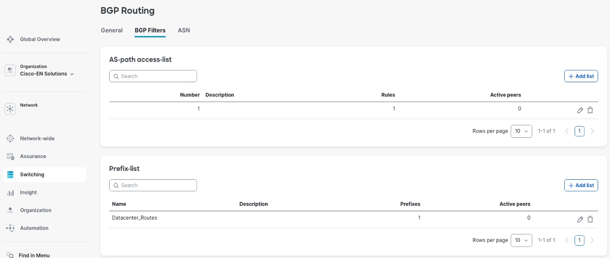
These filters are attached to the BGP Peer Groups at Switching > BGP Routing > General > BGP Routers > BGP Peer Groups > Peer Group Settings.
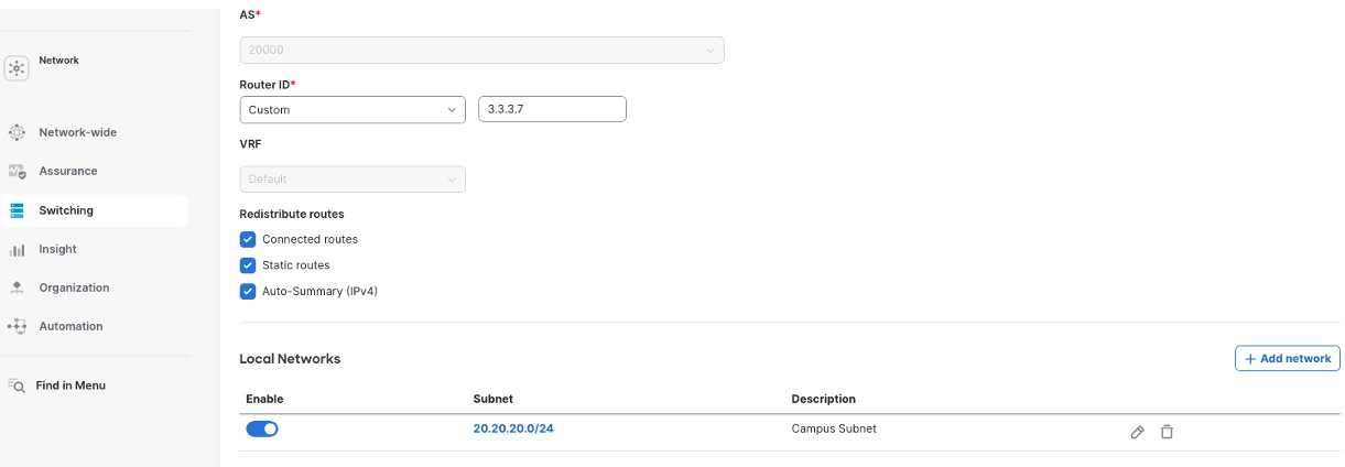
Network advertisement configuration
You can set up network advertisements for your campus network using the dashboard. You need to choose which local subnets, like employee networks, guest Wi-Fi, and management networks, should be shared with the data center using BGP. The BGP setup lets you advertise networks that are directly connected, static routes, and combined network ranges. This approach gives you flexible control over which campus resources the data center can access, while still keeping security and network separation in place.
Procedure 10. To configure the local subnets to be advertised:
Navigate to the Switching > BGP Routing > BGP Router.
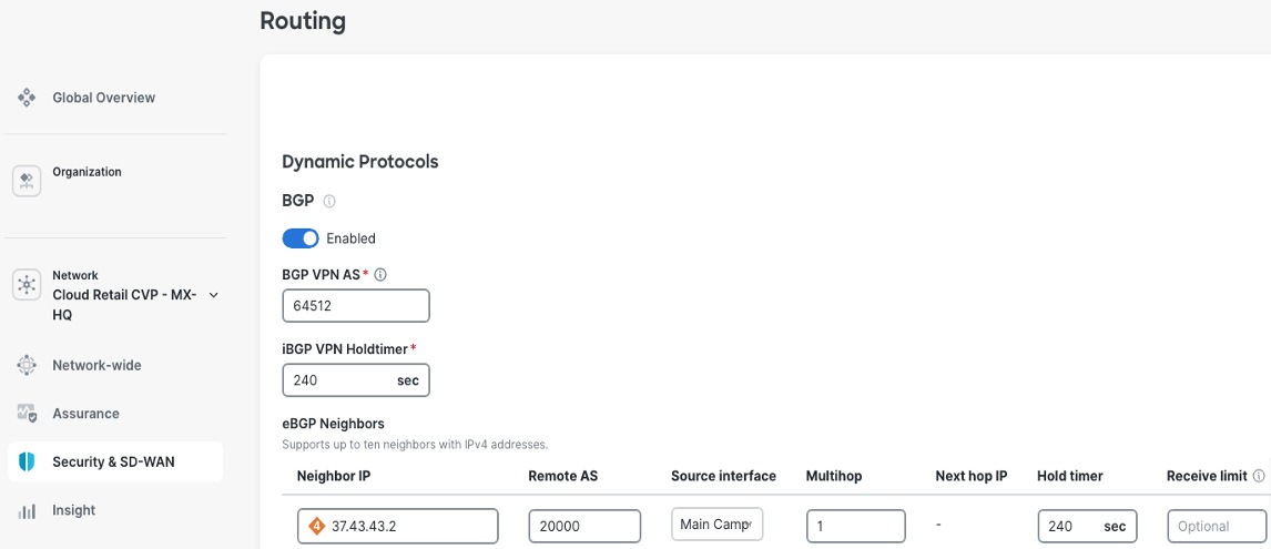
The Campus Meraki MX, deployed in SD-WAN Hub mode, can establish either eBGP or iBGP peering with the Catalyst 9500 collapsed core switches to enable dynamic route exchange. After successful peering is established between the 9500 SVI and the Meraki MX, campus routes (SVIs defined on the 9500) will be visible in the Meraki MX routing table, learned through BGP. Similarly, datacenter routes appear in the 9500 routing table, where these routes are learned by the Campus Meraki MX from the Datacenter Meraki MX (also deployed in SD-WAN Hub mode) through iBGP over the Meraki AutoVPN overlay, and then automatically redistributed to the 9500 through the BGP peering.
Detailed configuration guidance for Meraki MX BGP implementation can be found in the official Meraki documentation at Border Gateway Protocol (BGP).
Procedure 11. To configure the campus MX BGP neighborship to the 9500 core:
Step 1. Navigate to Security & SD-WAN > Configure > Routing,
Step 2. When using iBGP, on the MX routing end, select Allow transit so that the datacenter routes can be sent to the 9500 from the MX.
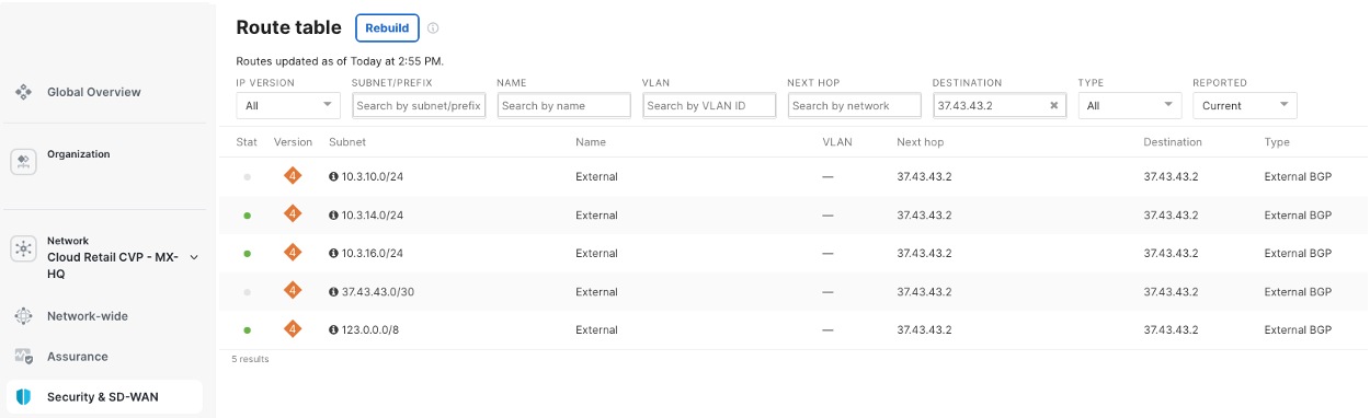
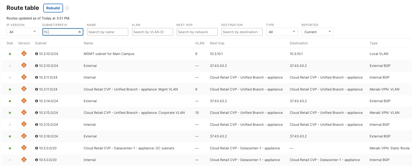
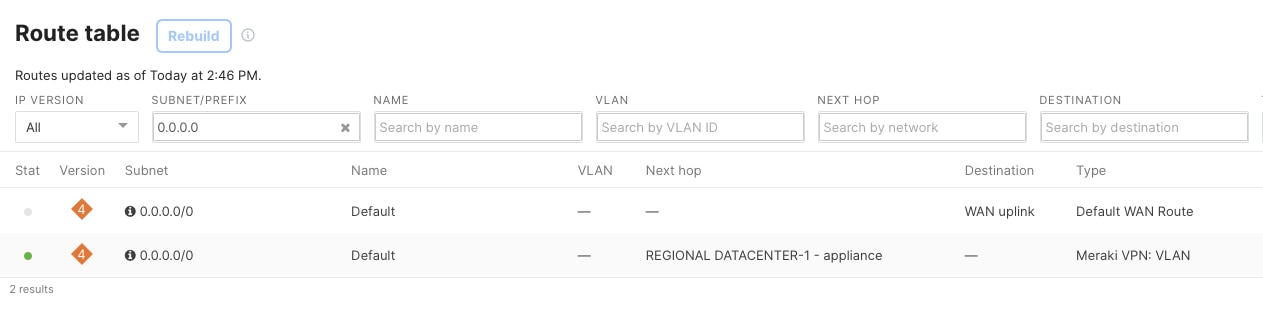
Procedure 12. To check the campus MX routing table:
Step 1. Navigate to Security & SD-WAN > Monitor > Route table.
Step 2. View the campus routes received from the 9500 Core BGP neighborship.
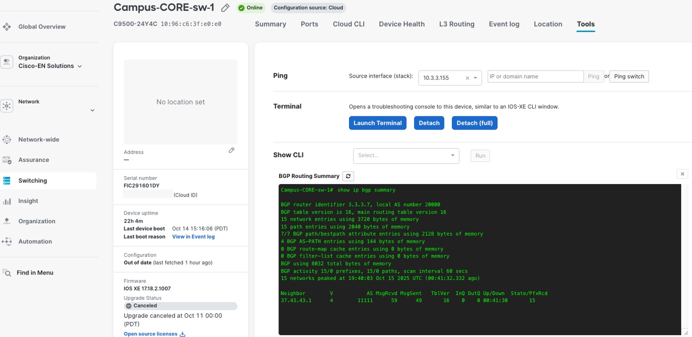
On the Cisco 9500 switch, you can check the status of BGP connections, neighbor states, route advertisements, and network convergence events using the ‘Terminal tool’ in the Meraki Dashboard. This tool gives you command-line access to run commands like show ip bgp summary, show ip bgp neighbors, and show ip route bgp so you can verify these details in real time. This helps you monitor and troubleshoot BGP directly from the dashboard interface.
The ‘Show CLI’ tool also provides the BGP state information seen in this example.
Redundancy and high availability
The distribution and access layer design implements multiple redundancy mechanisms ensuring business continuity for retail headquarters operations:
Link-level redundancy
All uplinks use EtherChannel (LACP) configurations providing both bandwidth aggregation and automatic failover capabilities, with traffic automatically redistributed across remaining links during failures.
Device-level redundancy
Distribution layer StackWise Virtual pairs and access layer StackWise stacks eliminate single points of failure, with automatic failover occurring within seconds of device failure detection.
Path-level redundancy
Dual-homed access switches maintain connectivity to both distribution switches, ensuring continued operation during distribution switch maintenance or failures.
Power redundancy
Distribution switches use dual power supplies with connections to separate electrical circuits, protecting against power supply failures and electrical circuit outages.
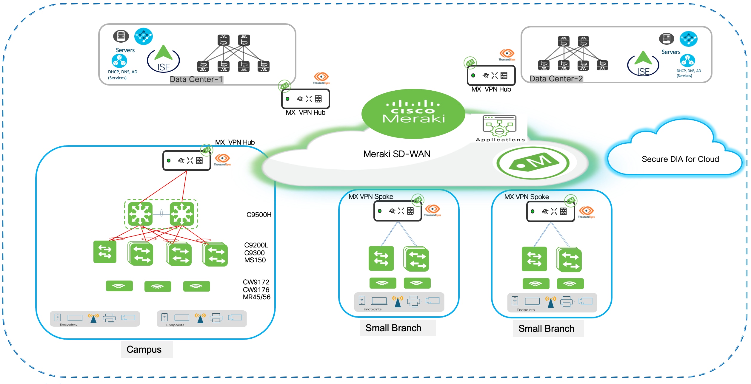
Data center connectivity for common enterprise service access
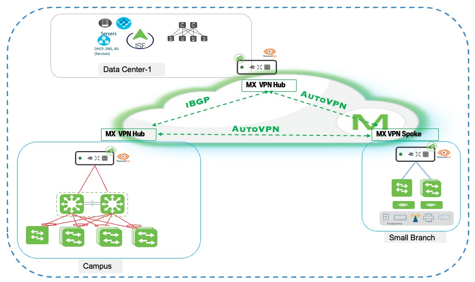
The retail campus core layer establishes high-performance, resilient connectivity to the enterprise data center infrastructure through the Meraki SD-WAN. The retail architecture implements a hierarchical hub-and-hub topology, a data center MX VPN Hub and a campus MX VPN Hub.
The data center MX hub serves as the central aggregation point, integrating with ISE to provide centralized 802.1X authentication and network access control while hosting core enterprise services including DHCP, DNS, Active Directory, and business-critical applications such as inventory management and payment processing systems.
The campus MX Hub aggregates local campus switching and wireless infrastructure and establishes AutoVPN connectivity to both the data center hub and retail store branches.
The SD-WAN architecture provides intelligent traffic routing where critical enterprise traffic destined for ISE authentication and internal applications traverses AutoVPN tunnels to the data center hub, while SaaS and internet-bound traffic uses local breakout or routes through the campus hub for optimal performance. This is further detailed in the section Meraki SD-WAN deployment.
Procedure 13. To check the campus MX routing table:
Step 1. In the Campus network on the dashboard, navigate to Security & SD-WAN > Monitor > Route table.
Step 2. View the campus routes received from the 9500 Core eBGP neighborship, datacenter routes received from the DC MX Hub (through iBGP) and the retail branch routes received from the spoke MX.
Corporate wireless deployment
The retail headquarters wireless infrastructure provides enterprise-grade connectivity supporting corporate employees, executives, conference facilities, and operational areas throughout the campus environment. This deployment leverages Wi-Fi 7 technology with advanced security, quality of service, and centralized authentication capabilities, delivering superior performance and user experience for business-critical wireless applications while maintaining the simplified cloud management benefits of the Meraki platform.
AP onboarding to Meraki Dashboard
Initial device registration
Meraki MR APs are onboarded to the Meraki Dashboard through a streamlined claiming process that establishes cloud management connectivity and prepares devices for deployment.
Procedure 14. To onboard Meraki MR APs:
Step 1. Access the Organization > Configure > Inventory page.
Step 2. Add access point serial numbers either individually or through bulk CSV upload.
Step 3. Associate devices with the organization.
Step 4. Make the devices available for network assignment.
Step 5. To establish ownership and enable cloud management capabilities, using the dashboard, enter each AP’s unique serial number and claiming code (printed on the device label.)
When claimed into organizational inventory, APs are assigned to the corporate campus network construct created during initial setup.
Step 6. Navigate to Organization > Inventory.
Step 7. To assign devices to the appropriate campus network, select the claimed APs, and select Add to network.
This assignment links the APs to the campus switching infrastructure, VLAN configurations, and wireless policies defined for headquarters operations, ensuring consistent behavior and centralized management across the entire wireless deployment.
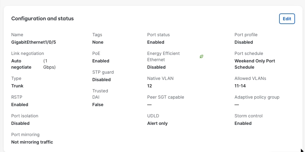
The switchport settings on which the AP is connected to differs if we want the same AP to broadcast multiple SSID.
For multiple SSID, the switch port needs to be in trunk mode. The native VLAN of the trunk port is the VLAN in which the AP gets its management IP address. The ‘allowed VLANs’ on the trunk ports correspond to the VLANs that the SSIDs use.
For zero-touch provisioning, the network assignment APs automatically download their configurations from Meraki cloud infrastructure when connected to the network and powered on. The dashboard interface displays real-time onboarding status showing devices as they connect to the cloud.
Step 8. Download firmware updates if needed, and transition to operational status.
Step 9. Monitor zero-touch provisioning through Network-wide > Monitor > Access Points where device status, firmware versions, and connectivity health display.
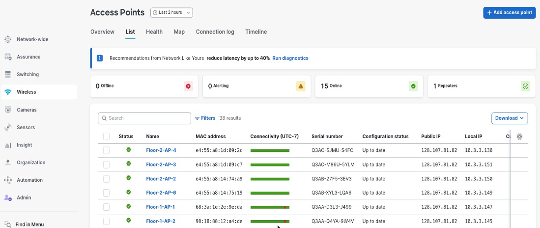
Step 10. Verify that all APs are properly onboarded and ready for wireless service deployment.
Wi-Fi deployment for corporate headquarters
The retail headquarters wireless infrastructure provides enterprise-grade connectivity supporting corporate employees, executives, conference facilities, and operational areas throughout the campus environment, delivering superior performance and user experience for business-critical wireless applications while maintaining simplified cloud management through the Meraki platform.
Corporate and guest Wi-Fi implementation
Corporate-SSID implements WPA3-Enterprise with 802.1X/RADIUS authentication, assigns clients to corporate VLAN (VLAN 11) with centralized DHCP from headquarters infrastructure, provides full network resource access, and enforces application-based QoS prioritizing business traffic. Guest-SSID uses captive portal authentication, operates in local bridged mode with DHCP services provided directly by MR APs, isolates clients to guest VLAN (VLAN 13) with internet-only access, implements bandwidth limitations (5 Mbps per client), and blocks inter-client communication ensuring complete network segmentation and security isolation from corporate resources.
The subsequent sections explain the various aspects of the Wi-Fi for both Corporate and Guest.
Security considerations
Corporate and guest wireless networks require distinct security architectures reflecting their different usage patterns. Corporate SSIDs typically implement WPA2-Enterprise or WPA3-Enterprise to provide strong authentication and encryption for organizational devices and users. WPA2-Enterprise uses 802.1X authentication with AES-CCMP encryption and remains widely deployed to support legacy devices requiring backward compatibility. WPA3-Enterprise continues to use 802.1X/EAP authentication but strengthens security through mandatory Protected Management Frames (PMF), stronger cryptographic algorithms, and support for a 192-bit security mode using AES-GCMP-256 and SHA-384. When paired with certificate-based EAP methods such as EAP-TLS, WPA3-Enterprise can provide forward secrecy and enhanced resistance to credential compromise. Organizations may deploy WPA2/WPA3 mixed or transition configurations to support both WPA2- and WPA3-capable clients, enabling phased modernization while maintaining compatibility across diverse corporate endpoint populations.
802.1X authentication
The Corporate SSID uses dot1x, which means users or devices must provide credentials that are checked against a central RADIUS server before they can access the network.
Procedure 15. To set up 802.1X authentication:
Step 1. In the dashboard, navigate to Wireless > Configure > Access Control.
Step 2. Under Security settings, select Enterprise with my RADIUS server.
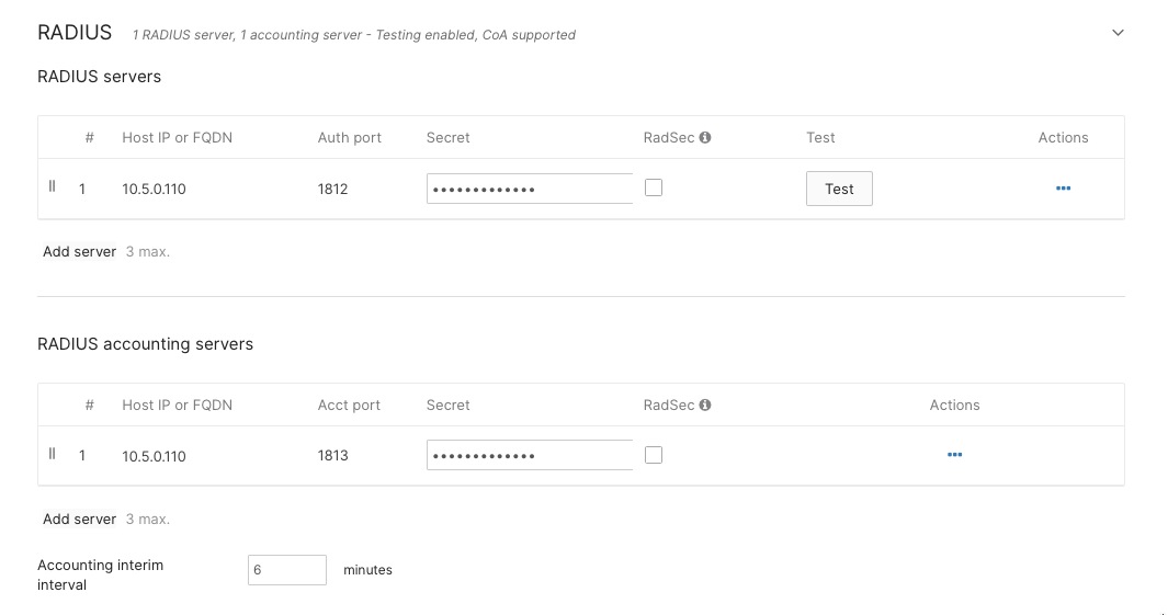
Step 3. Either add your RADIUS server details in the RADIUS section on this page or set them at the Organization level. You can use either Meraki authentication or an external RADIUS server, depending on your setup.
Step 4. For retail headquarters, enter the IP addresses of your Cisco ISE servers, set the shared secret for secure communication, and specify the authentication ports (usually UDP 1812 for authentication and UDP 1813 for accounting).
This setup ensures only authorized users or devices can join the Corporate Wi-Fi network.
Client DHCP and network assignment
VLAN assignment
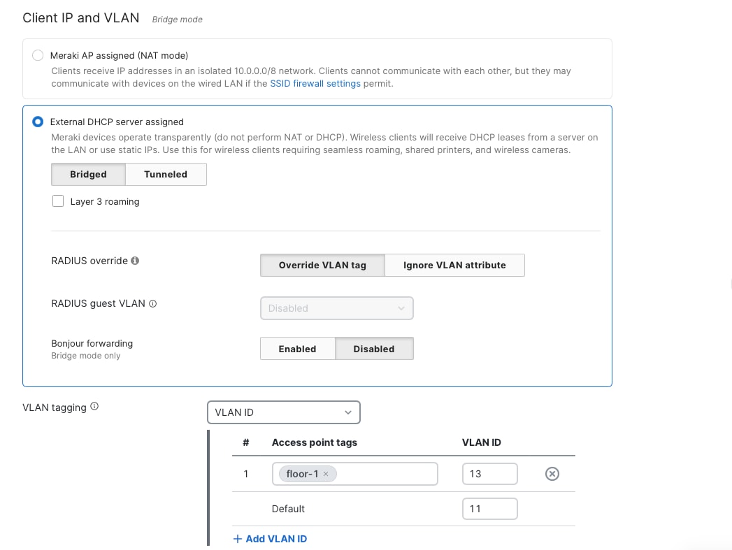
To make sure network segmentation and policies work correctly, you need to set up the Corporate SSID to use VLAN tagging. Assign wireless clients on this SSID to the corporate network VLAN, which is VLAN 10, in the Client IP and VLAN settings.
For corporate wireless clients, choose the option to use an external DHCP server. This means that wireless devices will get their IP addresses from central DHCP servers in the campus core or data center, instead of from local DHCP services on the APs or wireless controllers.
If you want to assign specific VLANs based on access point tags, you can also use the VLAN tagging section under Wireless > Configure > Access Control. This setup is helpful if you need the same SSID to be broadcast by different APs, but you want clients connected to different groups of APs to get IP addresses from different subnets. Since the VLAN ID are the same across wired and wireless clients, this helps ensuring wireless users receive the same network access and security policies as wired corporate users connected through access layer switches. This configuration supports dynamic VLAN assignment through RADIUS attributes enabling user- or group-specific VLAN placement, with executive users potentially assigned to a separate VLAN with enhanced network privileges while standard employees connect to the general corporate VLAN.
The Guest SSID uses open authentication, so users can connect without a password. However, they must go through a captive portal where they accept the terms of service before getting access. This method provides a balance between security and convenience, it collects basic user information for accountability, but doesn’t require guests, visitors, or contractors to have accounts or go through complicated login steps.
For guest network IP addresses, you can use either Meraki AP assigned (NAT mode) or Local MX DHCP.
Firewalling and traffic shaping
Corporate Network
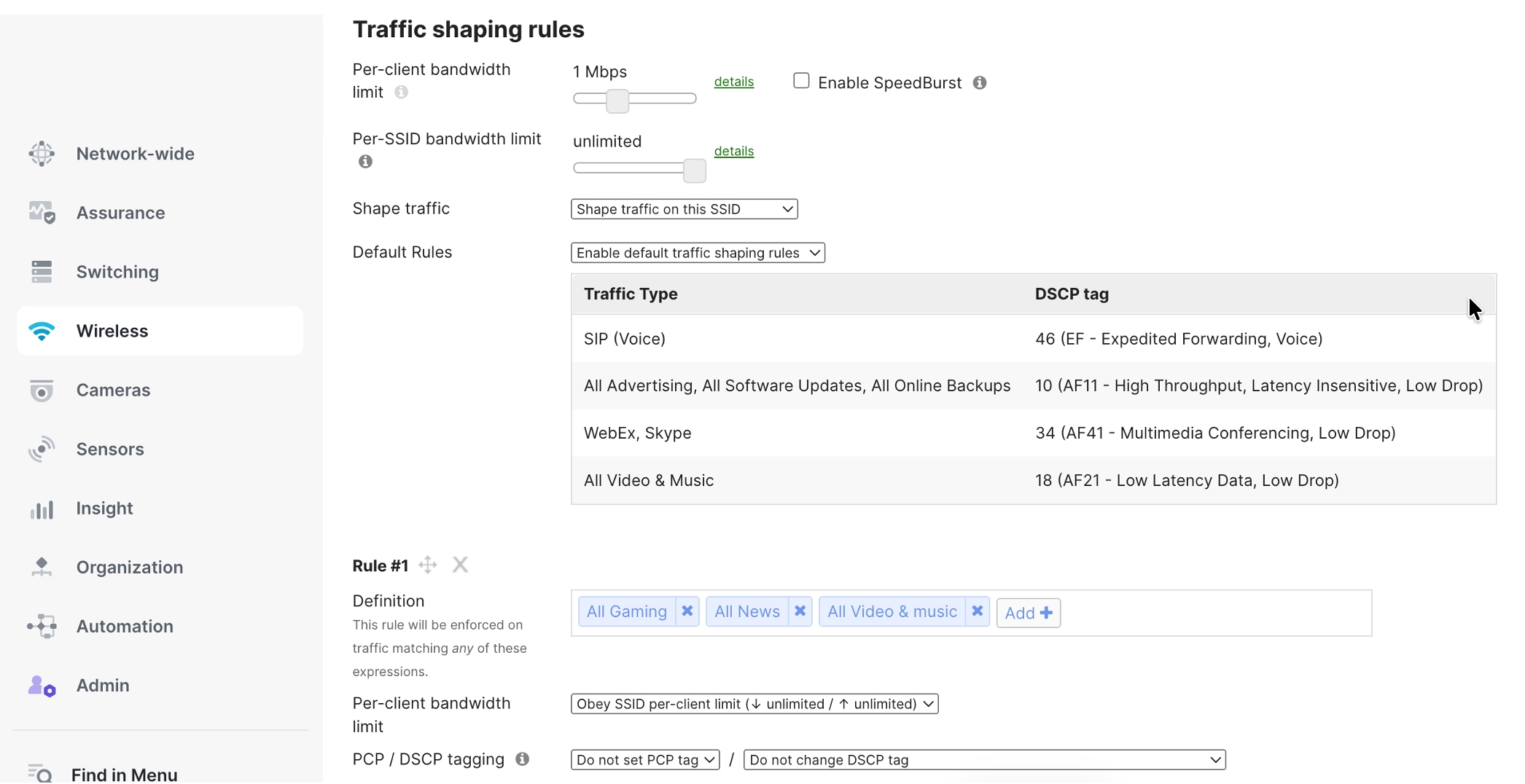
Implement Layer 3 firewall rules allowing corporate VLAN (VLAN 11) access to headquarters resources, data center applications, and internet destinations with application-aware traffic shaping prioritizing business-critical applications—VoIP and video conferencing receive highest priority, collaboration tools and web browsing medium priority, while bulk downloads receive lower priority ensuring optimal performance for time-sensitive corporate communications. Configure per-application bandwidth guarantees and DSCP marking maintaining end-to-end QoS across campus infrastructure.
Guest Network
Set up strict firewall rules so that devices on the guest VLAN (VLAN 13) can only access the internet. Block all access to company resources, internal networks, and other VLANs to keep your organization’s data safe from untrusted devices.
Limit each guest’s internet speed to 5 Mbps for downloads and 2 Mbps for uploads. This stops any one guest from using too much bandwidth. Also, block peer-to-peer file sharing, VPN connections, and lower the priority for streaming services. This helps make sure there’s enough bandwidth for business needs, while still letting guests browse the web and check email.
To set this up, go to Wireless > Firewall & Traffic Shaping, pick the SSID you want to secure, and add your Layer 3 and Layer 7 firewall rules.
You can apply firewall rules at the SSID level as described, or on the MX Next Generation Firewall by going to Security & SD-WAN > Configure > Firewall and adding rules under Layer 3 > Outbound rules.
Per-client bandwidth limits
Set a bandwidth limit for each user so that no one person can use up all the wireless network’s capacity. This helps make sure all employees have a fair share of the network. For example, you can set each device to a maximum of 100 Mbps for downloads and 50 Mbps for uploads. This is enough for most work tasks but will stop things like backups, large downloads, or streaming from slowing down the network for others in the same area.
You can set these limits by going to Wireless > Firewall & Traffic Shaping > Per-client bandwidth limit. You can adjust the limits based on how many people use the network and the capacity of each access point in different parts of your campus.
The wireless clients after authenticating are placed on the Corporate SSID. Clients can be viewed at Network-wide > Clients.
The retail network infrastructure leverages Meraki SD-WAN capabilities to establish secure, high-performance connectivity between corporate headquarters campus and distributed store locations across the retail enterprise. This SD-WAN architecture implements intelligent path selection, application-aware routing, and automated failover capabilities ensuring business continuity for mission-critical retail applications including point-of-sale systems, inventory management, corporate communications, and centralized business services.
Campus-to-data center communication
The retail campus core layer establishes high-performance, resilient connectivity to the enterprise data center infrastructure through the Meraki SD-WAN. The retail architecture implements a hierarchical hub-and-spoke topology with three distinct tiers: a data center MX VPN Hub, a campus MX VPN Hub, and distributed branches as MX VPN Spokes. The data center hub serves as the central aggregation point, integrating with ISE to provide centralized 802.1X authentication and network access control while hosting core enterprise services including DHCP, DNS, Active Directory, and business-critical applications such as inventory management and payment processing systems.
The campus MX Hub aggregates local campus switching and wireless infrastructure and establishes AutoVPN connectivity to both the data center hub and retail store branches. Branch locations deploy MX Spoke appliances configured to establish AutoVPN tunnels to both hub locations, creating a resilient multi-hub topology. This design enables branch spokes to access data center resources for enterprise services and authentication while maintaining optimized paths for cloud and internet connectivity. This three-tier hub-and-spoke design delivers centralized control of core services at the data center while providing geographic redundancy and application performance optimization through the campus hub and distributed spoke architecture.
When two MX appliances are both configured in hub mode, they establish hub-to-hub AutoVPN peering and automatically exchange routing information bidirectionally. Each hub advertises its locally-configured subnets and aggregated spoke routes to the peer hub, enabling full reachability across the topology. The data center hub learns campus subnets while the campus hub learns data center subnets, with both hubs propagating the complete route table to their respective spoke sites. This automatic hub-to-hub route exchange creates a seamless routing domain without manual route redistribution or static route configuration. AutoVPN automatically exchanges routing information between the data center hub, campus hub, and branch spokes without manual configuration. Each MX advertises its locally-configured subnets to connected hubs, which propagate these routes to all participating spokes. Branch spokes learn data center and campus networks dynamically, establishing optimal paths through the AutoVPN mesh. This zero-configuration route distribution ensures automatic connectivity as new branches deploy or network changes occur across the topology.
Campus-to-branch communication
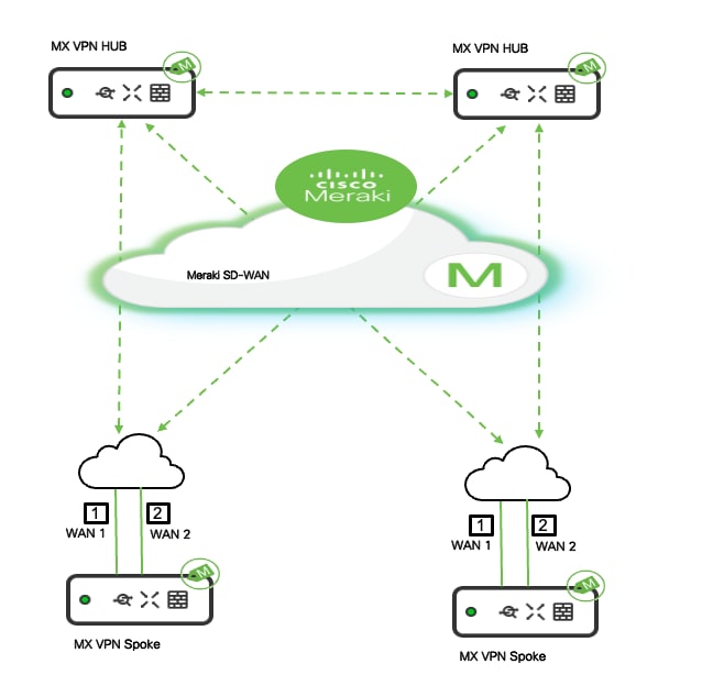
AutoVPN mesh architecture: Meraki SD-WAN establishes AutoVPN mesh connectivity between headquarters and all store locations, creating secure IPsec VPN tunnels that automatically form and maintain encrypted communications across the retail network. The campus headquarters and Datacenters operate as the HUB in the SD-WAN topology with MX security appliances deployed at the network edge providing VPN concentration, traffic aggregation, and centralized policy enforcement. Store locations function as SPOKE with local MX appliances establishing VPN tunnels back to headquarters hubs, enabling secure communication for branch-to-headquarters traffic flows while maintaining local internet breakout capabilities for guest Wi-Fi and cloud application access. 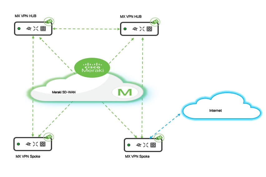
Hub and spoke topology
The AutoVPN deployment uses a hub-and-spoke topology optimized for retail operations where the majority of traffic flows between individual stores and central headquarters rather than store-to-store communication.
Corporate campus MX appliances are configured in the Meraki Dashboard.
Procedure 16. To configure as VPN concentrators:
Step 1. Navigate to Security & SD-WAN > Site-to-site VPN.
Step 2. Enable hub mode, allowing these devices to accept VPN connections from hundreds of branch locations simultaneously.
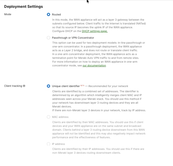
Branch store MX appliances are configured in spoke mode with headquarters specified as the hub destination. This configuration automatically establishes encrypted tunnels and registering with the VPN concentrator for centralized management and traffic forwarding. Branch MX is configured in the ‘Routed Deployment’ mode advertising the branch subnets over the AutoVPN. It forms VPN tunnels to the corporate campus and the datacenters.
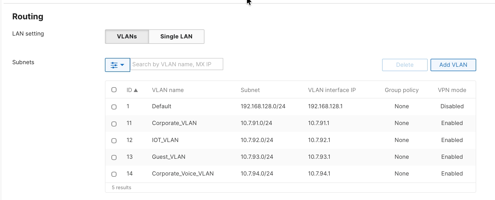
Procedure 17. To choose the MX deployment mode and the subnets that needs to be advertised into the AutoVPN:
Navigate to Security & SD-WAN > Addressing & VLAN.
Automatic tunnel establishment
Meraki AutoVPN simplifies site-to-site VPN deployment by eliminating manual IPsec configuration, pre-shared key distribution, and complex routing protocol setup traditionally required for site-to-site VPN deployments, but administrators must still configure the VPN topology through the Meraki Dashboard.
Procedure 18. To define hub and spoke relationships:
Step 1. Navigate to Security & SD-WAN > Site-to-site VPN within each network to configure the VPN role.
Step 2. Designate headquarters MX appliances as VPN hubs by selecting Hub mode, enabling them to accept incoming VPN connections from multiple branch locations.
Store location MX appliances are configured as VPN spokes:
Step 3. Select Spoke mode and select which hubs the spoke should establish tunnels with from the available hub list.
After the VPN topology is defined through the dashboard, tunnel establishment becomes automatic when branch MX appliances power on and establish internet connectivity. The spoke automatically discovers the designated hub through Meraki cloud infrastructure, initiates encrypted tunnel establishment using cloud-managed keying material, and begins forwarding traffic according to defined routing and security policies without requiring administrators to manually configure IPsec parameters, exchange pre-shared keys, or troubleshoot tunnel negotiation issues at each site.
This cloud-orchestrated VPN provisioning dramatically reduces deployment complexity compared to traditional VPN solutions, enabling rapid store openings and seasonal location deployments where administrators simply configure the VPN role and hub selection through the dashboard rather than performing complex IPsec configuration, while still maintaining flexibility to customize tunnel behavior, failover policies, and traffic routing on a per-site basis when business requirements demand location-specific VPN architectures.
Procedure 19. To configure the role of the MX in the AutoVPN:
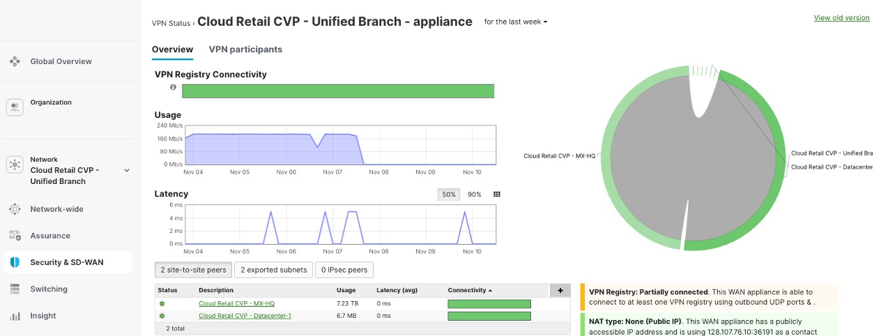
Step 1. Navigate to Security & SD-WAN > Site-to-Site VPN.
Step 2. View the status of the AutoVPN and the Routing table of the Site by navigating to Security & SD-WAN > Addressing & VLANs > VPN Status and Route Table.
For the MX tunnel scaling guidelines, see MX Sizing Guide and Principles.
Traffic routing and optimization
AutoVPN uses smart traffic routing to decide which network traffic should go through secure VPN tunnels to the main office (headquarters) and which traffic should use the local internet connection at each branch location.
● Traffic for corporate apps, central databases, and services hosted at headquarters is automatically sent through VPN tunnels. This keeps the data secure and ensures company policies are followed.
● Traffic that is meant for the internet, such as guest Wi-Fi, public cloud services, and SaaS applications, can use the local internet connection at the branch office. This reduces the amount of data going over the main network (WAN) and can make applications run faster because they are closer to the cloud providers.
By default, any branch office traffic that does not match the list of enterprise networks shared by the head office is routed directly to the internet. This is because of the default route (0.0.0.0/0) set on the branch device (Spoke MX).
If the branch is set up in "full-tunnel" mode, where all traffic is sent to the head office by default, you need to create VPN Exclusion Rules. These rules specify which types of traffic should use the local internet connection instead of the VPN tunnel.
Procedure 20. To select the IPv4 default route option for the site:
Navigate to Security & SD-WAN > Site-to-Site VPN.
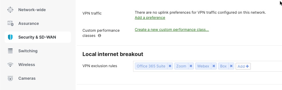
Procedure 21. To define the local internet breakout and VPN exclusion rules for the site:
Navigate to Security & SD-WAN > SD-WAN & Traffic Shaping.
High availability and WAN resilience
WAN high availability
Meraki MX security appliances at both headquarters (hub) and stores (spoke) use smart WAN uplink selection and load balancing to make sure your network runs smoothly. They automatically switch to another internet connection if the main one fails or slows down. MX appliances support multiple WAN uplinks, including primary and backup broadband connections (such as cable or fiber), to keep your business running even if the main internet connection has problems.
Additionally, you can set up the MX appliance in High Availability mode using a warm-spare unit for extra backup. When both MX devices are deployed in warm-spare mode and each has two WAN connections (WAN1 and WAN2), the site has four layers of redundancy for its internet connections.
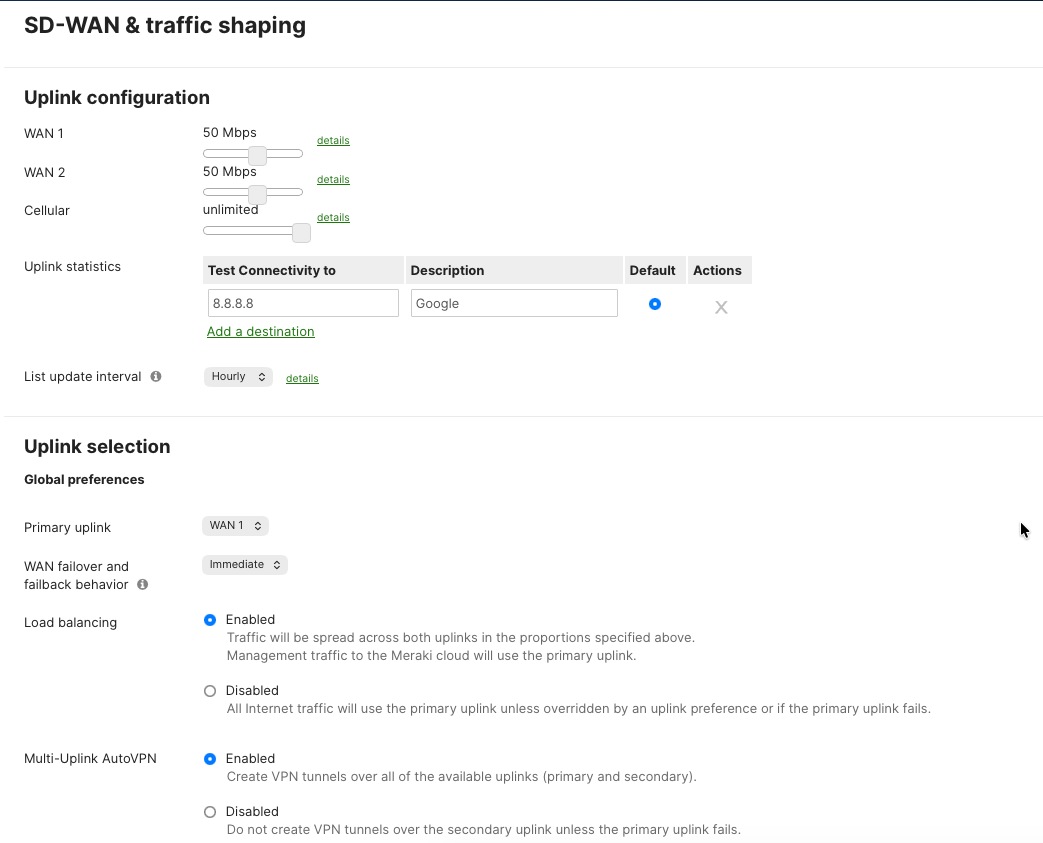
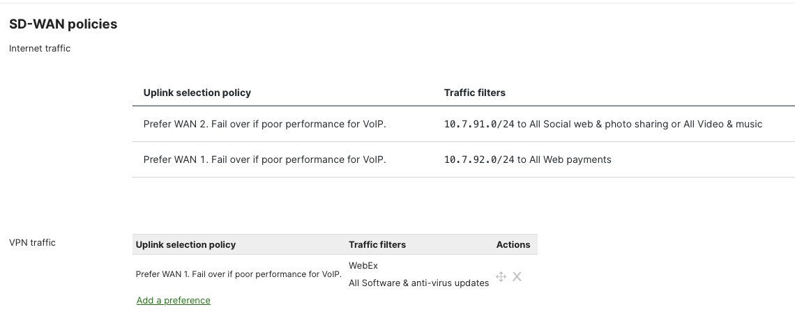
Uplink selection policies
The Meraki MX lets administrators choose which internet connections (WAN links) different kinds of traffic or applications should use. This is done through policy-based uplink selection, which helps match business needs and control costs.
You set up uplink selection policies in the Meraki Dashboard by going to Security & SD-WAN > Traffic Shaping. Here, you can create rules to make sure that important business traffic—like point-of-sale (POS) transactions and voice-over-IP (VoIP) calls—always use the main, high-speed internet connection. Less important traffic, such as large file transfers, software updates, or backups, can be sent over backup or secondary connections.
This setup makes sure that critical business applications get the fastest and most reliable connections, while non-essential tasks use backup links. It helps use the total available bandwidth more efficiently, manages costs for connections that charge by usage, and ensures that vital business traffic is always prioritized.
You can also configure the system for "active-active" load balancing. This means both internet connections are used at the same time, splitting VPN traffic and other data flows between them. This way, all available bandwidth is used, and neither connection is left unused during normal operations.
Procedure 22. To define the Uplink selection and preferences:
Navigate to Security & SD-WAN > SD-WAN & Traffic Shaping.
Performance-based load balancing
The MX platform continuously monitors WAN uplink performance metrics including latency, jitter, packet loss, and available bandwidth, dynamically adjusting traffic distribution to maintain optimal application performance. When performance degradation is detected on a primary uplink—such as increased latency during peak hours or packet loss indicating congestion. The MX automatically shifts traffic to alternate uplinks maintaining application performance without manual intervention. This active performance monitoring operates continuously with sub-second detection of quality degradation enabling rapid response to changing WAN conditions that could impact business operations or customer experience.
Procedure 23. To define the policies:
Navigate to Security & SD-WAN > SD-WAN & Traffic Shaping.
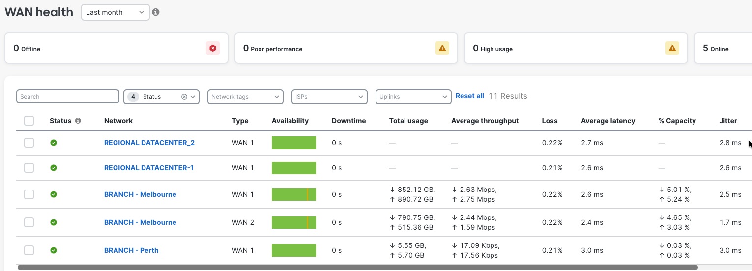
WAN health monitoring with ThousandEyes
Meraki Dashboard integrates with Cisco ThousandEyes to provide end-to-end WAN visibility beyond the branch edge. ThousandEyes agents deployed on MX appliances continuously monitor application performance, path visualization, and ISP health across the internet and multi-cloud environments. Synthetic testing validates connectivity to critical SaaS applications, while hop-by-hop path analysis identifies where performance degradation occurs, whether in your network, ISP, or application provider infrastructure, enabling faster troubleshooting and proactive resolution.
Procedure 24. To integrate ThousandEyes to your organization:
Navigate to Insights > Configure > Active Application Monitoring.
Procedure 25. To check the WAN health for your networks:
Navigate to Insights > WAN Health.
Retail store and branch deployment
Retail store branch deployment uses the BaC infrastructure to quickly and consistently set up networks at hundreds of locations. By using Terraform providers and pre-tested YAML templates, new stores can be up and running within hours with automated configuration, requiring no manual setup.
The security framework follows zero-trust principles. It uses WPA3-Enterprise for wireless point-of-sale (POS) devices and 802.1X authentication for wired POS systems. Meraki MX appliances provide advanced threat protection, including AMP, IPS/IDS, and next-generation firewall features to help meet PCI DSS requirements.
Firewall policies protect POS traffic by keeping payment processing on separate, secure network segments that only allow connections to authorized payment gateways. Direct internet access policies allow guest Wi-Fi and cloud apps to use local internet connections, which reduces WAN usage and improves performance through smart VPN exclusion rules.
Guest Wi-Fi is set up with custom captive portals and isolated network segments that prevent access to company resources. Bandwidth management ensures POS systems get priority, and firewall rules restrict guest users to internet-only access while blocking communication between guest devices.
Application monitoring tools give real-time insight into POS performance, payment gateway connectivity, and overall network health. Automated alerts notify you immediately about connectivity issues, security events, or performance problems that need urgent attention.
Meraki Location Analytics offers customer footfall analytics, such as visitor counting, dwell time, repeat visitor tracking, heat maps, and engagement metrics. This helps with decisions on staffing and merchandise placement while staying compliant with GDPR and CCPA.
Altogether, this branch deployment approach brings automated setup, strong security, smart traffic management, and valuable business analytics, all managed centrally through the Meraki Dashboard for consistent policy enforcement, easier troubleshooting, and a unified view of the retail network.
BaC toolkit introduction
BaC uses Infrastructure as Code (IaC) principles to automate branch network deployment, eliminating manual setup and replacing it with automated, easy-to-manage provisioning. This helps retail businesses quickly and consistently deploy, manage, and scale networks across many store locations using Cisco’s proven designs and automation tools.
With this approach, network teams define branch services using pre-tested configuration templates that include Cisco’s best practices for routing, security, and wireless and wired infrastructure. This creates consistent and standardized networks, while still allowing flexibility for different store sizes and layouts, from small shops to large flagship stores.
The BaC toolkit includes a dedicated Terraform provider, which serves as the link between your overall network plans and the specific device settings. It automatically turns business needs into detailed device configurations using built-in API connections. There is also a library of ready-to-use YAML templates with optimized settings for routing, security, wireless, and switching.
Retailers can use templates designed for different types of stores (such as small, standard, superstore, or flagship), as well as functional templates for POS network isolation, customer Wi-Fi, and IoT device setup. This accelerates store openings, allowing new network infrastructure to be production-ready in just minutes, with all configurations tracked and managed in Git repositories.
This method greatly reduces manual work by preventing configuration errors through pre-deployment checks, allowing instant restoration if problems occur, and generating complete records for audits. Teams using DevOps can take advantage of IaC features and CI/CD pipelines to enforce testing, approvals, and quick responses to business needs.
BaC brings software engineering practices to enterprise networking, making network infrastructure a strategic business asset while still allowing customization for franchises and integration with key retail systems like POS and inventory management.
To use BaC for retail deployments, you’ll need Terraform, which automates the process of turning configuration files into actual Meraki device settings. Cisco provides a detailed BaC Git repository with pre-validated Terraform configs, YAML templates for various store types, and deployment patterns with proven security and compliance practices for retail. You can find this at Cisco's official Branch as Code repository. Step-by-step instructions for installing Terraform, setting up your environment, and preparing for deployment are in the Reference section of this document. For more on YAML config templates, see Network as Code: Overview.
BaC repository setup
After a successful Terraform installation and environment configuration as detailed in Technical references, the next step involves obtaining the BaC repository containing all necessary provider code, modules, and pre-validated YAML configuration templates for Meraki deployments. Cisco maintains the Network-as-Code (NaC) Meraki repository. This repository includes the Terraform provider modules, branch deployment templates, and retail-specific configuration examples that form the foundation for automated store network provisioning.
Procedure 26. To clone the BaC repository:
Step 1. Execute these command to clone the repository to your local machine or virtual machine where Terraform is installed:
bash
git clone https://wwwin-github.cisco.com/netascode/nac-meraki.git
cd nac-meraki
Step 2. After cloning the repository, verify that the correct Terraform providers are defined in the main.tf file. The repository includes pre-configured provider definitions that should reference:
Terraform Cisco Meraki Network-as-Code Module: nac-meraki
Meraki Provider: CiscoDevNet/meraki
Step 3. Review the main.tf file to confirm these providers are properly specified and compatible with your Terraform installation version. The repository structure includes directories for templates, modules, and example configurations that will be customized for your specific retail deployment requirements.
Step 4. The Meraki HUB/Datacenter networks are manually created outside of the BaC framework. We need to import those networks into Terraform state using this command syntax:
terraform import 'module.meraki.meraki_network.network["ORG_NAME/NETWORK_NAME"]'<ORG_ID>,<NETWORK_ID>
Configure the Meraki Dashboard Organization API key as an environment variable, enabling Terraform to authenticate and communicate with the Meraki organization for automated infrastructure-as-code deployment and management workflows.
With the repository successfully cloned and providers verified, you can continue to create and customize branch YAML configuration files tailored to your retail store deployment requirements, leveraging the provided templates as starting points for small, medium, and large store formats.
Deploy store network using BaC toolkit
After you have set up the BaC toolkit and configured Terraform as described earlier, the branch deployment process starts by setting up the basic network infrastructure in the Meraki Dashboard. Once this foundation is in place, you can use BaC templates to automatically set up the full store configuration.
In the BaC file structure, the /data directory contains all the YAML files that define the network and its settings. You can use the provided templates to create branches or configurations by entering values for the variables, or you can create your own YAML files if needed.
Note: All the subsequent sections in this document show example YAML configurations and the corresponding results in the dashboard.
Procedure 27. To deploy a branch:
Step 1. Have the Cloud ID of the network devices be claimed into the ORG and added to the network?
In this sample YAML file, which claims the devices into the ORG, creates a network and adds the devices into the branch network.
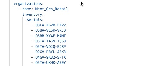
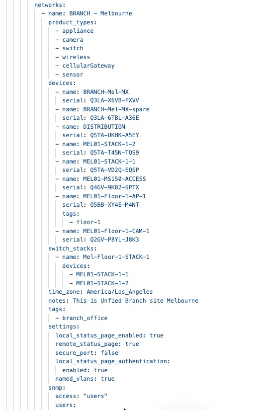
Step 2. Configure the access switchports with the assignments for POS devices, VoIP phones, APs, and so on.
Note: By default, all the switch ports are set to trunk mode when the switch is managed by cloud. It is important, for security purposes, to configure all the unused ports to access mode and disable them.
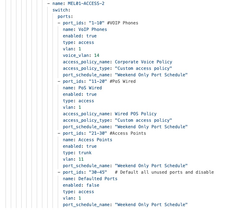
Step 3. Create on the upstream MX device, the branch user networks for onboarding all the end devices and users.
Note: The client subnets created on the MX appliance, can act as DHCP server themselves or can relay the DHCP requests to a centralized DHCP server for the entire enterprise.
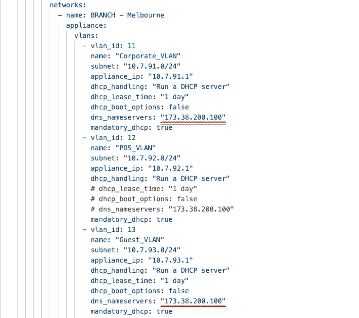
With network infrastructure successfully deployed through BaC, including device claiming, network creation, VLAN provisioning, the retail store network is now prepared for client device onboarding configurations that enable end-user connectivity and operational functionality.
Typical VLAN segmentation for the network would consist of corporate VLANs for data and voice, IoT and Guest segmentation. The preceding deployment steps established the network foundation with configured subnets for POS systems (VLAN 12 – 10.7.92.0/24), employee devices (VLAN 11 – 10.7.91.0/24), guest (VLAN 13 – 10.7.93.0/24), and IoT infrastructure (VLAN 14 – 10.7.94.0/24), creating the segmented network architecture required for secure, policy-driven client access. Now that these foundational network segments are operational with proper IP addressing, DHCP services, the focus shifts to implementing authentication mechanisms, access policies, and service configurations that allow retail-specific client devices to connect, authenticate, and access appropriate network resources based on device type, user identity, and business requirements.
Retail store security framework
Zero-trust network access principles
Zero-trust network access principles in retail stores implement a "never trust, always verify" security model where every device, user, and application request undergoes continuous authentication and authorization regardless of network location. This approach segments POS systems, guest networks, and IoT devices into isolated zones with granular access controls, ensuring payment data protection and PCI DSS compliance while preventing lateral movement during security breaches.
Secure connectivity for POS for wired and wireless
Point-of-sale systems require stringent access controls and security configurations to maintain PCI DSS compliance and protect payment card data. For wired POS devices, configure dedicated switchport access policies through Meraki Dashboard by navigating to Switch > Switchports and assigning polices to the ports with 802.1X authentication enabled, requiring device certificates or user credentials validated against centralized RADIUS servers before granting network access. Enable port security limiting MAC address counts per port, configure DHCP snooping preventing rogue DHCP servers, and apply traffic shaping policies prioritizing POS transaction traffic for optimal performance during peak periods.
For wireless POS devices including mobile payment terminals and handheld inventory scanners, create a dedicated SSID (for example, "POS-Secure") configured with WPA3-Enterprise security providing enhanced encryption and individualized data encryption protecting against passive eavesdropping. Configure the SSID through Wireless > SSIDs with 802.1X authentication requiring RADIUS validation, VLAN assignment to the dedicated POS network VLAN, and band steering preferring 5 GHz connectivity for reduced interference and improved throughput. Enable fast roaming (802.11r) ensuring seamless handoffs as mobile POS devices move throughout the store and configure minimum bitrate settings (12 Mbps recommended) preventing low-performance connections that could impact transaction processing times and customer experience.
These examples of the YAML files for this config for wired POS device onboarding:
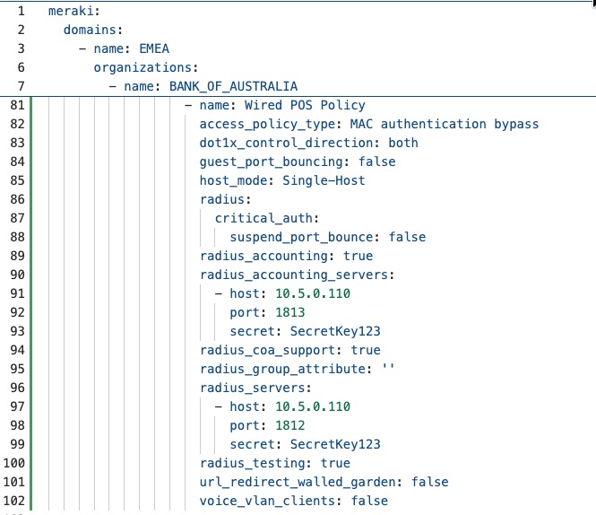
This YAML when run in terraform using ’terraform apply’, will result in the creation of the below access policy on the Meraki dashboard.
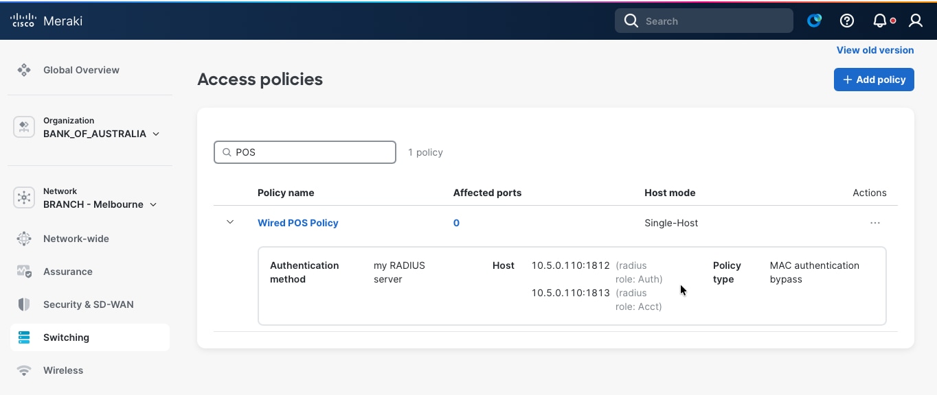
These examples of the YAML files for this configuration for wireless POS device onboarding:
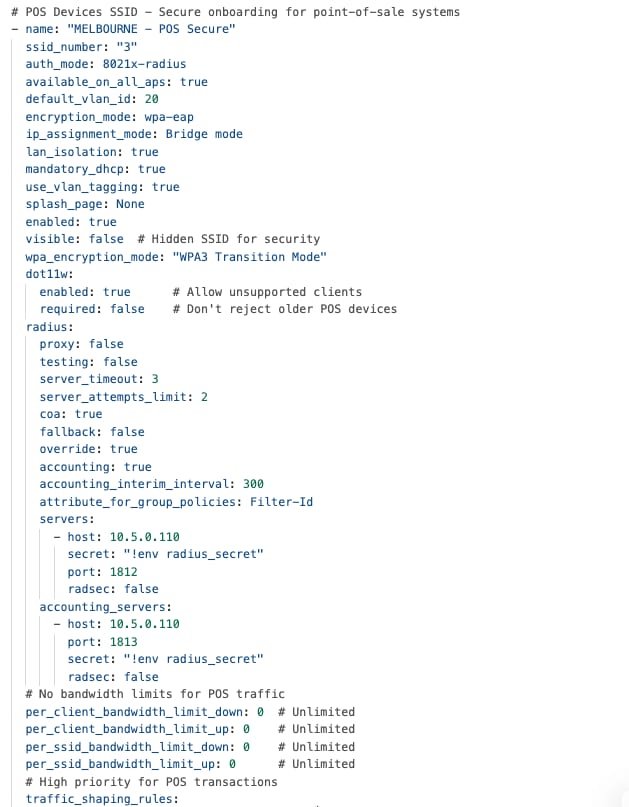
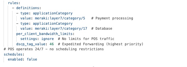
This YAML when run in terraform using ’terraform apply’, will result in the creation of the below SSID on the Meraki dashboard.
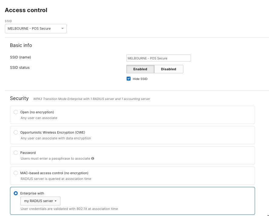
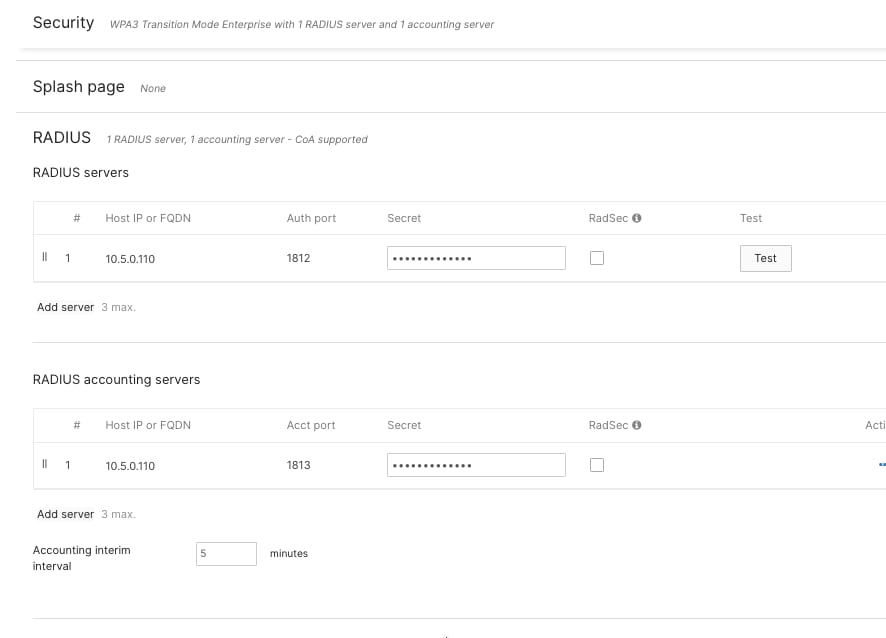

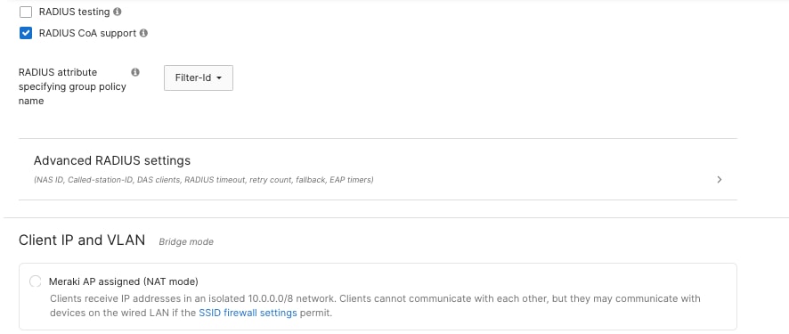
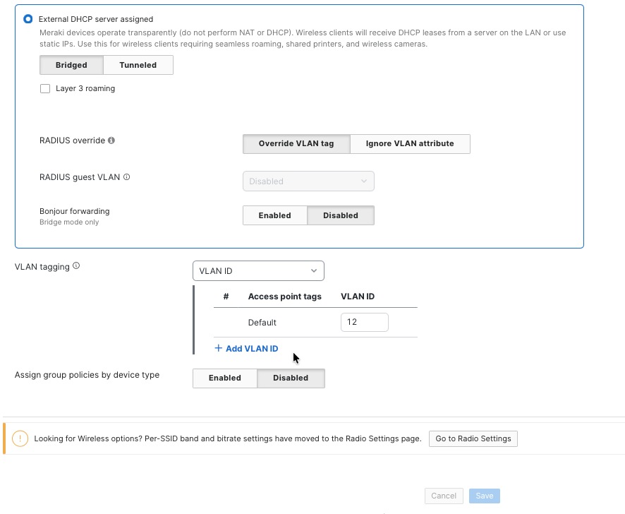
Similar configurations can be used for Employee onboarding, IoT device onboarding, IP phones, and so on for the wired and wireless.
Threat protection and content filtering
Meraki MX security appliances in retail stores offer built-in threat protection features, such as Advanced Malware Protection (AMP), Intrusion Prevention System (IPS), and Intrusion Detection System (IDS), to help protect payment systems and business operations from cyber threats.
Procedure 28. To set up threat protection:
Step 1. Navigate to Security & SD-WAN > Threat Protection in the dashboard.
Step 2. Turn on AMP for real-time scanning of files and to catch threats that may be discovered later.
Step 3. Enable IPS/IDS in Prevention mode with a balanced ruleset to automatically block exploit attempts and harmful traffic.
Procedure 29. To set up content filtering:
Step 1. Navigate to Security & SD-WAN > Content Filtering.
Step 2. Block unwanted categories, such as adult content, illegal sites, and peer-to-peer file sharing, while allowing access to important business applications.
Step 3. Block specific websites, like competitor sites, by adding them to a custom URL list.
These settings help keep all store locations secure, support business operations, and maintain compliance with regulations.
These examples of the YAML files for enabling AMP and IPS/IDS with Content filtering:
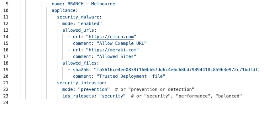
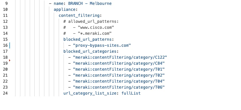
This YAML when run in terraform using ’terraform apply’, results in the creation of the below on the Meraki dashboard.
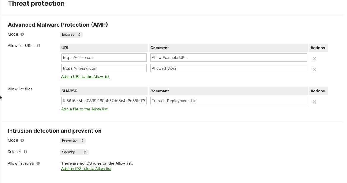
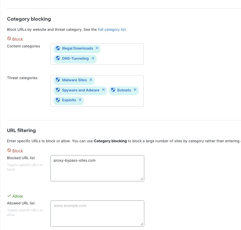
Firewall policies to secure POS traffic for NGFW at MX
Point-of-sale systems represent the most critical security concern in retail networks as they process sensitive payment card data requiring strict PCI DSS compliance and protection against data breaches that could result in significant financial penalties, reputational damage, and loss of customer trust. Comprehensive firewall policies implemented on Meraki MX security appliances create multiple layers of defense isolating POS systems from unauthorized access while permitting only essential payment processing communications.
POS network segmentation foundation
The security architecture begins with dedicated VLAN assignment placing all POS devices on VLAN X with an isolated subnet (for example, 10.10.10.0/24), creating complete Layer 2 and Layer 3 separation from employee networks, guest Wi-Fi, IoT devices, and back-office systems. This segmentation establishes security boundaries enforced through stateful firewall inspection on the Meraki MX appliance, where all traffic crossing VLAN boundaries requires explicit firewall rule approval. The MX appliance serves as the enforcement point with its integrated next-generation firewall capabilities providing application awareness, intrusion prevention, and advanced malware protection specifically protecting the POS environment from sophisticated attacks targeting retail payment systems.
Firewall rule implementation on Meraki Dashboard
Procedure 30. To set up firewall rules:
Step 1. Navigate to Security & SD-WAN > Firewall in the dashboard for your store network.
Step 2. Here, you can create and manage Layer 3 firewall rules to protect POS traffic.
Step 3. The Meraki Dashboard makes it easy to add, arrange, and edit firewall rules, and it checks your rules for any errors before you apply them.
Step 4. Firewall rules are applied in order from top to bottom. The first rule that matches the traffic is the one that gets used, so the order of your rules is very important.
Step 5. Put your most specific and strict rules at the top, followed by broader rules.
Step 6. Add a final rule at the bottom to block all other traffic that isn’t specifically allowed. This helps make sure only approved traffic is permitted, and any other attempts are blocked and logged for security monitoring.
Layer 3 firewall rules configuration
Procedure 31. To configure Layer 3 firewall rules:
Step 1. Navigate to Security & SD-WAN > Firewall > Layer 3 Firewall Rules in the dashboard. Here, you’ll see the list of existing rules.
Step 2. Click Add a rule to create a new firewall policy.
Step 3. For each rule, set the following:
● Action: choose to allow or deny the traffic
● Protocol: specify the protocol (such as TCP or UDP)
● Source: set the source network or IP address
● Destination: set the destination network or IP address
● Port: enter the relevant port numbers
● (Optional) Logging: turn on logging if needed
● (Optional) Scheduling: set a time schedule if required
Step 4. Make sure to enable logging for all rules related to POS systems. This keeps detailed records needed for PCI DSS compliance.
Step 5. Logs are automatically sent to the Meraki cloud, where they are stored for analysis and future reference, supporting investigations and audit requirements.
These are examples of the YAML files for layer 3 firewalling rules for POS traffic on MX:
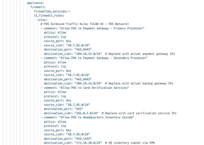
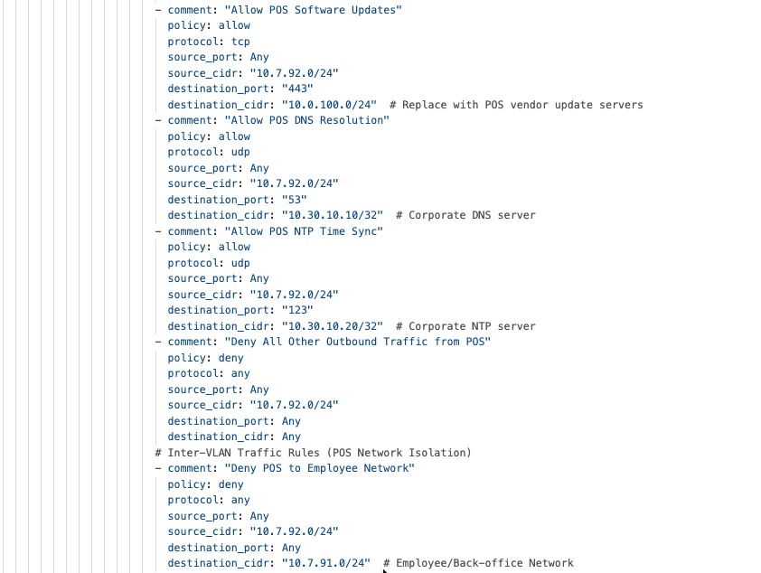
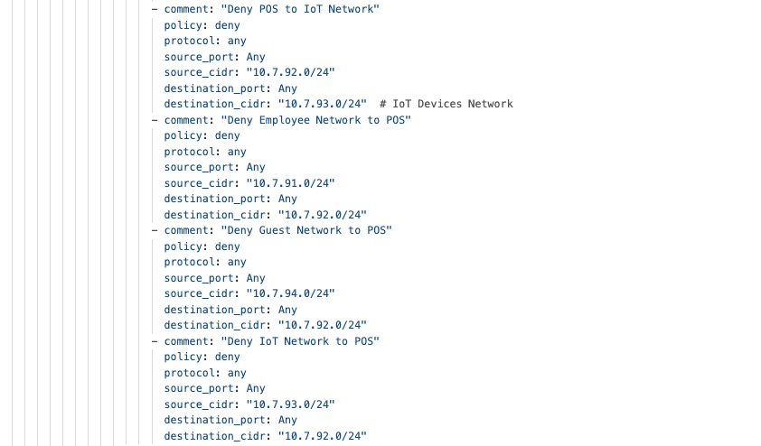
This YAML when run in terraform using ’terraform apply’, results in the creation of this example on the Meraki dashboard.
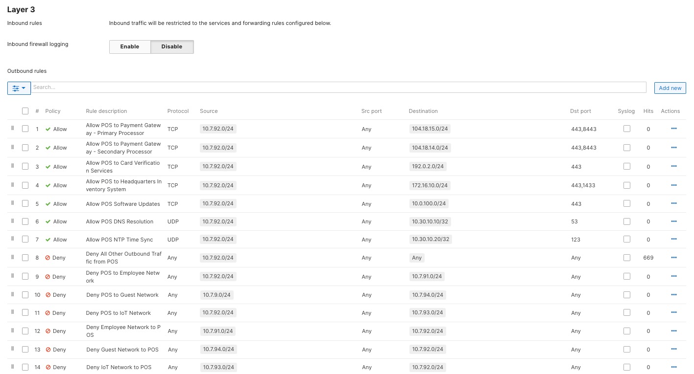
Direct Internet Access and VPN exclusion rules
Direct Internet Access (DIA), also known as local internet breakout, represents a strategic traffic management approach where specific applications and services access the internet directly from the branch location rather than routing through VPN tunnels back to corporate headquarters. This architecture optimizes network performance, reduces WAN bandwidth consumption, and improves user experience for cloud-based applications while maintaining security controls and centralized policy enforcement through the Meraki MX security appliance at each store location.
The split-tunnel architecture enables cloud applications like Office 365, video conferencing platforms, and SaaS business tools to leverage optimal routing to nearby cloud datacenters while corporate traffic continues flowing securely through VPN tunnels to headquarters, balancing performance optimization with security requirements and compliance obligations. Cloud SaaS applications including Office 365, Salesforce, Google Workspace, and collaboration platforms benefit significantly from local breakout. By default, all the branch traffic not matching any of the enterprise subnets advertised by the HUBs, is route to the internet owing to the 0.0.0.0/0 route on the branch Spoke MX. In the scenario of a full-tunnel mode, wherein the spoke does receive a default route from the HUB MX, VPN Exclusion Rules need to defined describing what kind of traffic need to take the local DIA.
These examples of the YAML files for VPN Exclusion rules on MX at the branch:
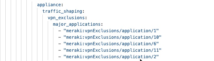
This YAML when run in terraform using ’terraform apply’, will result in the creation of this example on the Meraki dashboard.
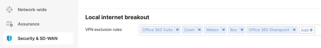
Application monitoring and network alerts
Traffic analytics on Meraki Dashboard
The Meraki Dashboard offers detailed application visibility and performance monitoring for all your retail locations using built-in traffic analytics. Cisco Catalyst 9000 switches use Network-Based Application Recognition (NBAR) to automatically identify and classify over 1,400 applications through deep packet inspection and behavior analysis. This lets you see exactly which applications are using your network and helps you set up intelligent quality of service (QoS), security controls, and bandwidth management.
With NBAR, the network can prioritize important business applications like POS systems and inventory management, while limiting less important or recreational traffic, all without manual protocol setup.
Procedure 32. To use traffic analytics:
Step 1. Navigate to Network-wide > Configure > General > Traffic Analysis to turn on the feature.
Step 2. To view network-wide analytics, go to Network-wide > Monitor > Traffic Analysis.
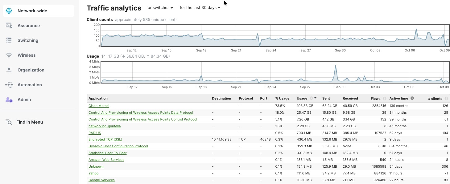
Procedure 33. To see analytics for individual devices:
Step 1. Navigate to Network-wide > Clients.
Step 2. Select any client to view detailed application usage for that device.
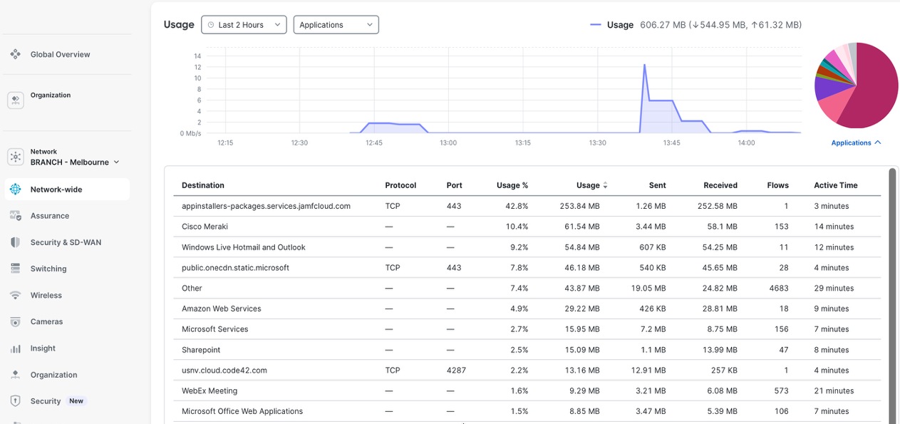
Network alerts
The Meraki Dashboard allows you to set up customizable alerts for your entire network, using email, SMS, or webhooks to send notifications. You can configure alerts for things like device connectivity problems, high bandwidth usage, configuration changes, security incidents, VPN status, and drops in application performance.
These real-time notifications help IT teams quickly address issues before they affect business operations. The system also keeps a history of alerts, which can be used for audits and compliance.
You can set up role-based alerting, so the right teams receive only the notifications that matter to them, reducing unnecessary alerts and helping resolve incidents faster across all retail locations.
Procedure 34. To set up alerts:
Step 1. Navigate to Network-wide > Configure > Alerts in the dashboard.
Step 2. Select the alert types and notification methods you want to enable.
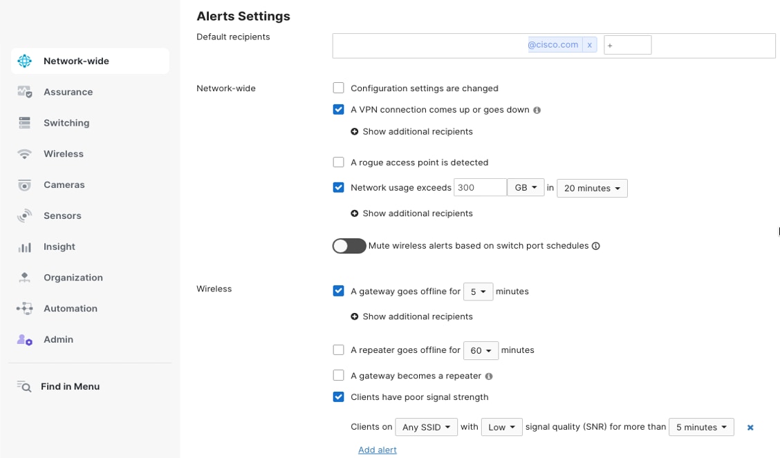
Customer footfall analytics
Meraki Dashboard's Location Analytics transforms Wi-Fi infrastructure into a customer intelligence platform by leveraging access point presence detection and engagement tracking. MR APs continuously detect Wi-Fi-enabled devices within range, capturing visitor counts, dwell times, repeat visit patterns, and foot traffic flows without requiring device connection. Administrators configure custom zones within floor plans—entrance areas, departments, checkout lanes—to analyze movement patterns and popular store sections. Real-time dashboards display current occupancy levels, peak traffic periods, and visitor demographics, while historical reporting reveals trends across days, weeks, or months. Integration with captive portals captures customer email addresses and demographics through Wi-Fi login, enriching analytics with identifiable visitor data. API exports enable seamless integration with CRM platforms, marketing automation systems, and business intelligence tools for actionable retail insights.
For a detailed explanation of how location analytics works with Meraki, see Location Analytics.
Procedure 35. To view the data for your organization:
Step 1. Navigate to Network-wide > Configure > General > Location and scanning > Analytics. Navigate to Organization > Location Analytics.
Step 2. Enable the feature.
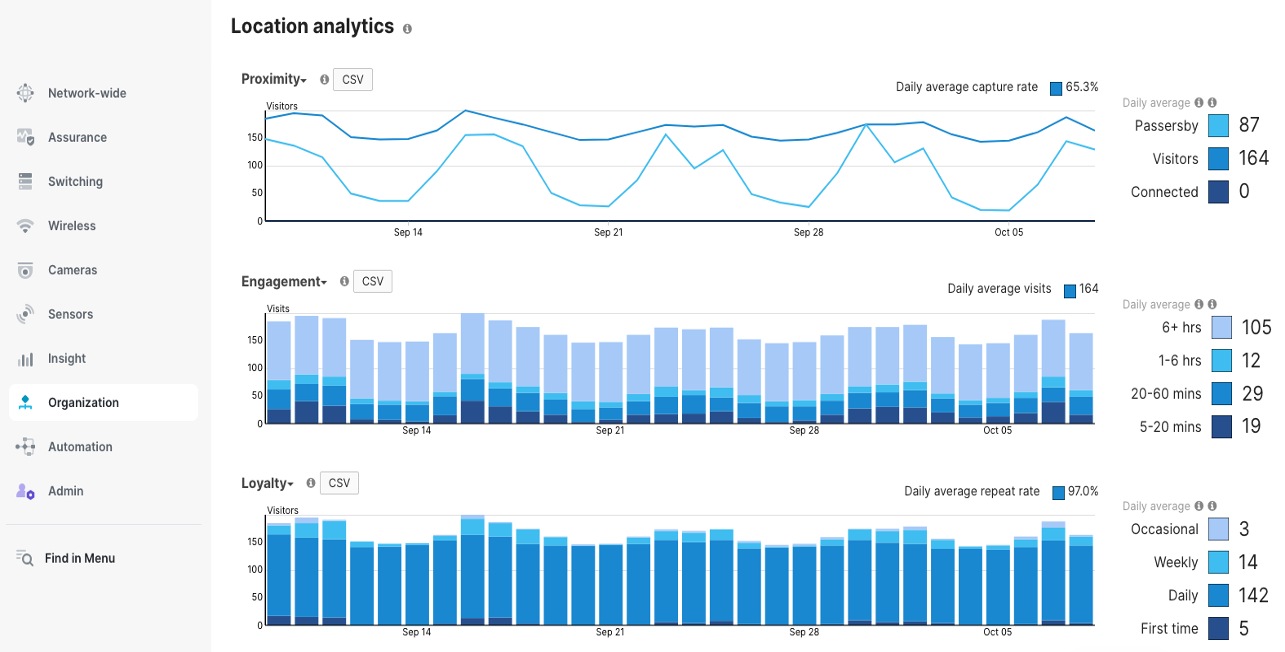
Seasonal scalability and rapid branch or store deployment
BaC transforms retail deployment through reusable YAML templates provided by Cisco. Templates encapsulate complete network configurations—VLANs, firewall rules, SSIDs, and AutoVPN relationships—as declarative code. Engineers customize deployments by modifying variable files containing location-specific parameters like site names and IP addressing, while core policies remain consistent. Terraform processes these templates, creating fully operational branches with zero manual configuration. Version control enables template evolution, rollback capabilities, and customizations while maintaining organizational standards. Template-based deployment ensures consistency across hundreds of stores while supporting location-specific customizations through variables. CI/CD integration validates configurations before deployment, preventing errors and enabling rapid rollback if needed, transforming multi-week deployment cycles into same-day store activations.
For seasonal pop-up stores or Black Friday expansions, devices are deployed directly from the box at retail locations—staff simply use cable power and uplink connections. BaC templates containing device serial numbers execute through Terraform, automatically claiming devices into the organization, assigning them to the newly created network, and pushing complete configurations from Meraki Dashboard cloud. Within minutes of physical connectivity, switches, APs, and security appliances download their policies and become fully operational, transforming branch deployment into true plug-and-play provisioning without any pre-staging or manual Dashboard interaction required.
Deploy new branches or stores easily by creating new networks referencing the templates (with the variable values customized for your organization). The templates are found in the data folder.
Procedure 36. To use the templates and deploy new networks:
Step 1. Start by exporting few variables for your organization.
Step 2. export MERAKI_API_KEY=cd18a3df66d236xxxxxxxxx738326
Step 3. export v3_auth_pass=Lablab123-Lablab123-
Step 4. export v3_priv_pass=Lablab123-Lablab123-
Step 5. export local_status_page_password=Lablab123-Lablab123-
Step 6. export snmp_passphrase=Lablab123-Lablab123-
Step 7. export domain=EMEA
Step 8. export org_name=RETAIL_AUSTRALIA
Step 9. The network variables are at data/pods_variables.yaml. Change the variable values to your requirement.
Step 10. When done, to create a new Branch, run terraform plan and terraform apply.
This streamlined BaC workflow enables rapid seasonal expansion and pop-up store deployments through repeatable, version-controlled operations. During peak retail periods like Black Friday or holiday seasons, organizations can deploy dozens of temporary locations simultaneously with consistent configurations, then decommission them post-season-transforming what traditionally required weeks of manual effort into automated, scalable infrastructure provisioning that aligns perfectly with dynamic retail business demands.
End-to-end application performance monitoring
Web application health monitoring with ThousandEyes
Meraki Dashboard integrates with Cisco ThousandEyes to provide end-to-end WAN visibility beyond the branch edge. ThousandEyes agents deployed on MX appliances continuously monitor application performance, path visualization, and ISP health across the internet and multi-cloud environments. Synthetic testing validates connectivity to critical SaaS applications, while hop-by-hop path analysis identifies where performance degradation occurs—whether in your network, ISP, or application provider infrastructure—enabling faster troubleshooting and proactive resolution.
To integrate ThousandEyes into your organization, navigate to Insights > Configure > Active Application Monitoring.
To check the application health for your networks, navigate to Insights > Web App Health.
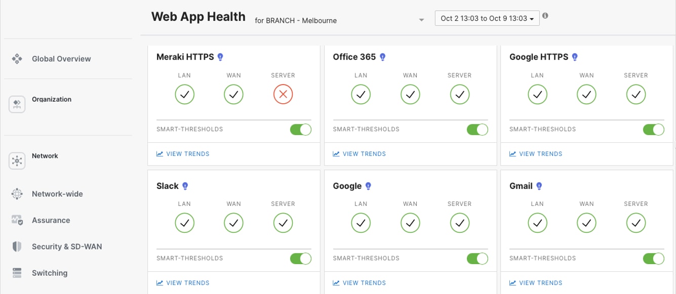
Detailed web application health monitoring is achieved by configuring HTTP Server tests or Page Load tests within the ThousandEyes dashboard targeting specific application endpoints. For example, Cisco Webex monitoring, administrators deploy synthetic transaction tests that simulate user login workflows, measure API response times, validate SSL certificate health, and track DNS resolution performance. ThousandEyes agents—deployed on Meraki MX appliances or cloud vantage points—execute these tests at configurable intervals, capturing metrics including availability, response time, throughput, and path visualization. The ThousandEyes dashboard presents multi-layered views showing network path performance, BGP routing changes, and application-layer metrics, enabling teams to distinguish between WAN issues, ISP problems, and Webex infrastructure degradation with hop-by-hop latency analysis and packet loss correlation.
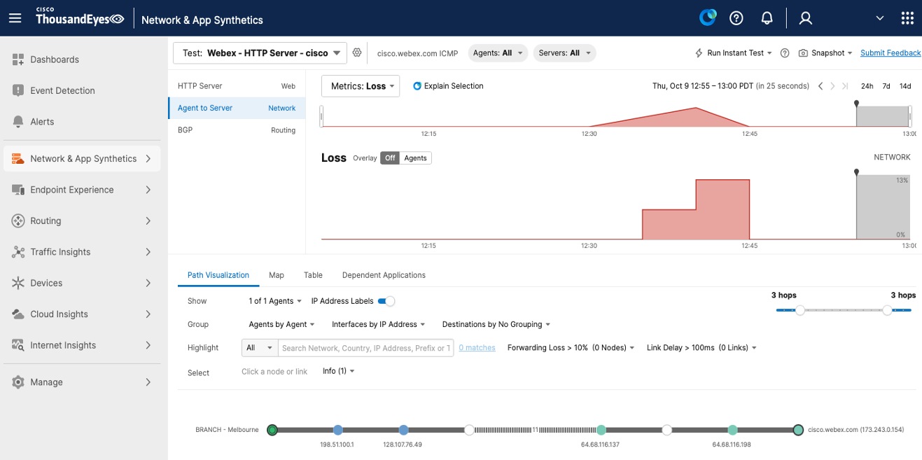
Organization-wide image management
Meraki Dashboard delivers centralized firmware management across the entire retail enterprise through automated, cloud-orchestrated update workflows. Administrators schedule firmware upgrades organization-wide or per network, with configurable maintenance windows minimizing business disruption during off-peak hours. Staged rollout capabilities enable phased deployments—test updates at pilot stores before enterprise-wide distribution—with automatic rollback on failure detection. Dashboard displays real-time firmware compliance status across all devices, highlighting outdated switches, APs, and security appliances requiring updates. Zero-touch automation eliminates manual intervention: devices automatically download firmware from Meraki cloud servers, install during scheduled windows, and report completion status. Version pinning ensures specific device models maintain tested firmware builds, while upgrade deferral options provide control over critical locations. Centralized visibility shows upgrade progress, success rates, and any failures requiring attention, transforming firmware management from a complex, time-consuming process into an automated, risk-mitigated operation across thousands of retail endpoints.
Procedure 37. To manage firmware upgrades in the Meraki Dashboard:
Step 1. Navigate to Organization > Firmware upgrades to see all your networks and the available firmware versions.
Step 2. Select the networks you want to upgrade, either one at a time or in groups.
Step 3. Select the firmware version you want to use (usually the "Recommended" version) and schedule the upgrade for a maintenance window that works for your business.
Step 4. For a safer rollout, you can upgrade a few pilot stores first, check for any problems, and then upgrade the rest of your sites.
Step 5. To manage switch upgrades in stages, go to Switching > Staged Upgrades, you can group switches into buckets and set the order in which they upgrade.
Step 6. Set up automatic upgrades and version pinning if needed to keep devices on a specific firmware version.
Step 7. Watch the upgrade progress with real-time status updates, check event logs to confirm upgrades were successful, and use the rollback option if you encounter any issues.
Step 8. Set up email or SMS alerts to get notified about upgrade progress or failures.
Technical references
● Onboarding Cloud-Managed Catalyst switches to the Meraki Dashboard