|
Cw_VM_Image
|
The name of Crosswork VM image in vCenter.
This value is set as an option when running the installer tool and does not need to be set in the template file.
|
|
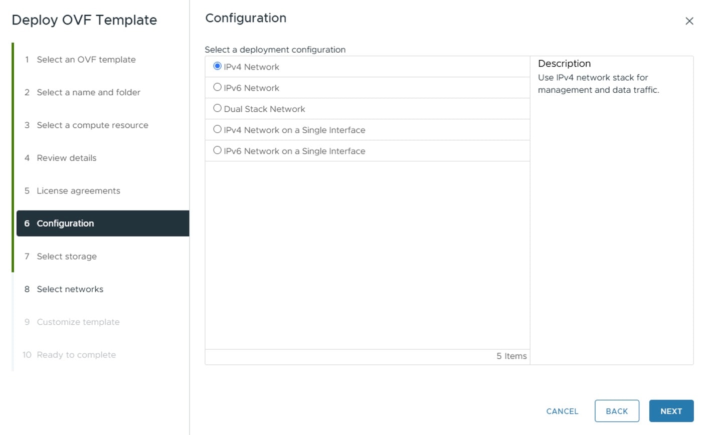
ClusterIPStack
|
The IP stack protocol: IPv4
|
|
vm_sizes
|
Create a custom profile as per your requirement. These two profiles are supported in Cisco Crosswork Planning:vm_sizes = {
"large" = {
vcpus = 16,
cpu_reservation = 24000,
memory = 128000
},
"xlarge" = {
vcpus = 24,
cpu_reservation = 32000,
memory = 256000
}
}
|
|
vcpus
|
The number of virtual CPU instances allocated for virtual machine.
|
|
cpu_reservation
|
The guaranteed minimum CPU resource allocation for virtual machine.
|
|
memory
|
The amount of memory allocation for virtual machine.
|
|
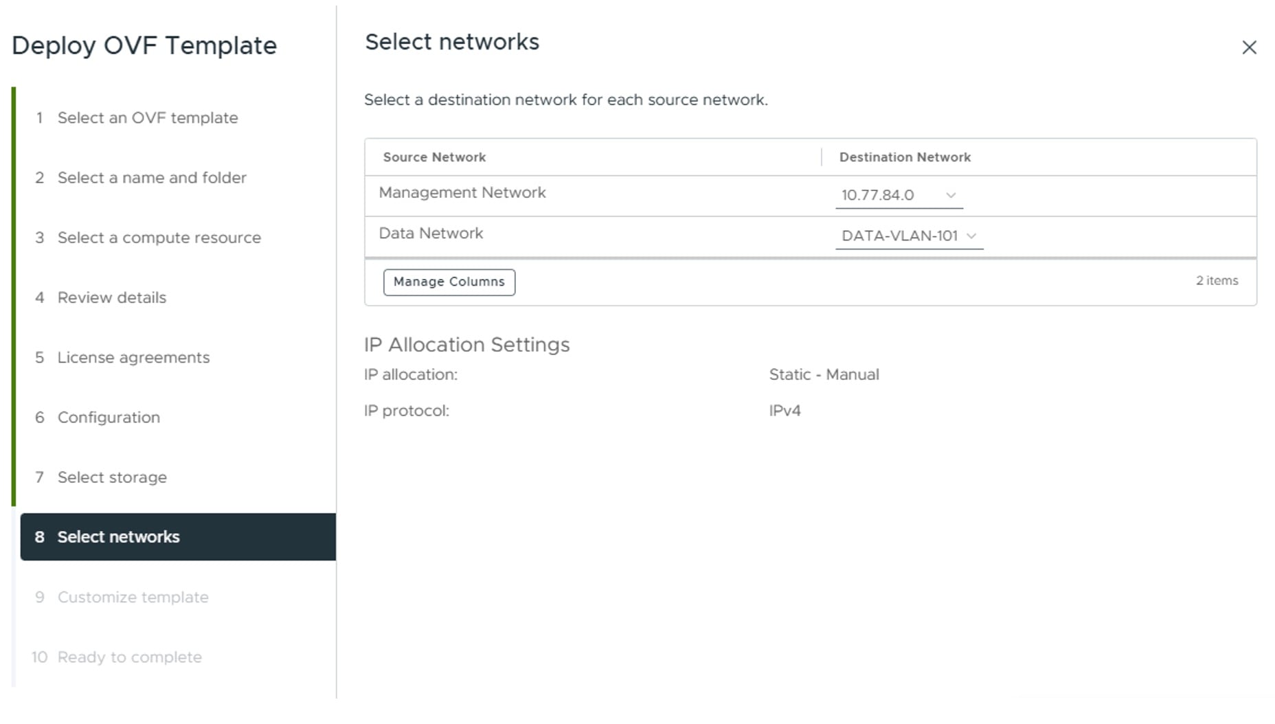
ManagementIPAddress
|
The Management IP address of the VM (IPv4).
|
|
ManagementIPNetmask
|
The Management IP subnet in dotted decimal format (IPv4).
|
|
ManagementIPGateway
|
The Gateway IP on the Management Network (IPv4). The address must be reachable, otherwise the installation will fail.
|
|
ManagementVIP
|
The Management Virtual IP for the Crosswork VM.
|
|
DataIPAddress
|
The Data IP address of the VM (IPv4).
|
|
DataIPNetmask
|
The Data IP subnet in dotted decimal format (IPv4).
|
|
DataIPGateway
|
The Gateway IP on the Data Network (IPv4). The address must be reachable, otherwise the installation will fail.
|
|
DataVIP
|
The Data Virtual IP for the Crosswork VM.
|
|
DNS
|
The IP address of the DNS server (IPv4). The address must be reachable, otherwise the installation will fail.
|
|
NTP
|
NTP server address or name. The address must be reachable, otherwise the installation will fail.
|
|
DomainName
|
The domain name used for the VM.
|
|
CWPassword
|
Password to log into Cisco Crosswork. When setting up a VM, ensure the password is strong and meets the following criteria:
-
It must be at least eight characters long, and include uppercase and lowercase letters, numbers, and at least one special
character.
-
These special characters are not allowed: backslash (\), single quote ('), or double quote (").
-
Avoid using passwords that resemble dictionary words (for example, "Pa55w0rd!") or relatable words. While such passwords may
meet the specified criteria, they are considered weak and will be rejected, resulting in a failure to set up the VM.
|
|
VMSize
|
VM size. Cisco Crosswork Planning supports the Large and XLarge profiles.
For more information, see Profile specifications.
|
|
VMName
|
Name of the VM.
|
|
NodeType
|
Type of VM. Choose "Hybrid".
|
|
IsSeed
|
Set to "True".
|
|
InitNodeCount
|
Set the value to 1.
|
|
InitMasterCount
|
Set the value to 1.
|
|
bckup_min_percent
|
Minimum percentage of the data disk space to be used for the size of the backup partition. The default value is 35 (valid
range is from 1 to 80).
Use the default value unless recommended otherwise.
|
Note
|
The final backup partition size will be calculated dynamically. This parameter defines the minimum.
|
|
|
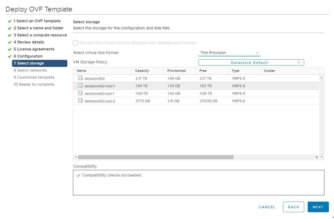
ThinProvisioned
|
Set to "false" for production deployments.
|
|
SchemaVersion
|
The configuration Manifest schema version. This indicates the version of the installer to use with this template.
Schema version should map to the version packaged with the sample template in the installer tool on cisco.com. You should
always build a new template from the default template provided with the release you are deploying, as template requirements
may change from one release to the next.
|
|
EnableSkipAutoInstallFeature
|
Pods marked as "skip auto install" will not be brought up unless explicitly requested by a dependent application or pod. By
default, the value is set as "False".
Set the value as "True".
|
Note
|
-
If left blank, the default value ("False") is automatically selected.
-
This parameter accepts a string value, so be sure to enclose the value in double quotes.
|
|
|
EnforcePodReservations
|
Enforces minimum resource reservations for the pod. If left blank, the default value ("True") is selected.
This parameter accepts a string value, so be sure to enclose the value in double quotes.
|
|
K8sServiceNetwork
|
The network address for the kubernetes service network. By default, the CIDR range is fixed to '/16'.
|
|
K8sPodNetwork
|
The network address for the kubernetes pod network. By default, the CIDR range is fixed to '/16'.
|
|
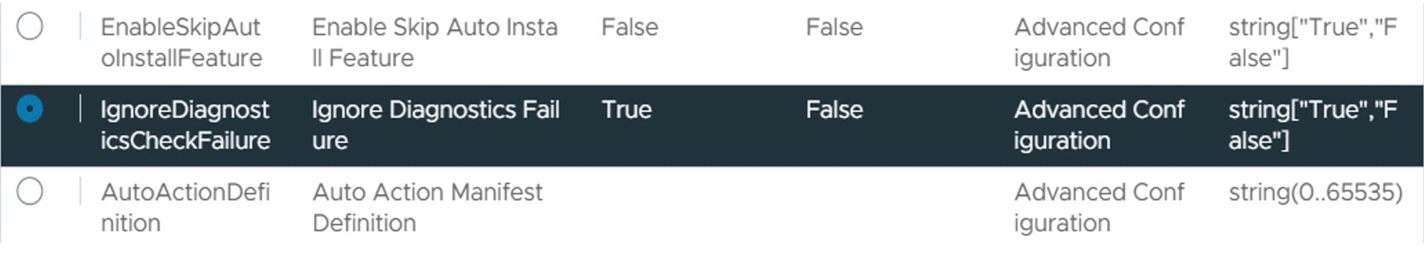
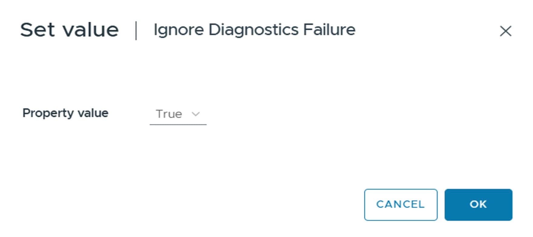
IgnoreDiagnosticsCheckFailure
|
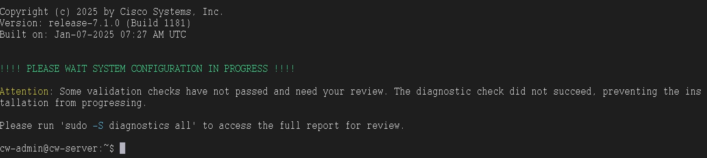
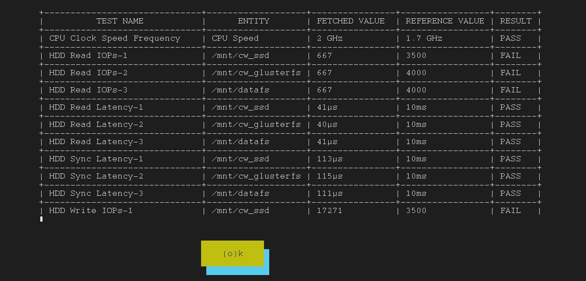
Used to set the system response in case of a diagnostic check failure.
If set to "false" (default value), the installation will terminate if the diagnostic check reports an error. If set to "true",
the diagnostic check will be ignored, and the installation will continue.
We recommend to select the default value. This parameter accepts a string value, so be sure to enclose the value in double
quotes.
|
Note
|
-
The log files (diagnostic_stdout.log and diagnostic_stderr.log) can be found at /var/log. The result from each diagnostic execution is kept in a file at /home/cw-admin/diagnosis_report.txt.
-
Use diagnostic all command to invoke the diagnostic manually on day N.
-
Use diagnostic history command to view previous test report.
|
|
|
ManagementVIPName
|
Name of the Management Virtual IP for the Crosswork VM. This is an optional parameter used to reach Crosswork Management VIP
via DNS name. If this parameter is used, the corresponding DNS record must exist in the DNS server.
|
|
DataVIPName
|
Name of the Data Virtual IP for the Crosswork VM. This is an optional parameter used to reach Crosswork Data VIP via DNS name.
If this parameter is used, the corresponding DNS record must exist in the DNS server.
|
|
EnableHardReservations
|
Determines the enforcement of VM CPU and Memory profile reservations. This is an optional parameter and the default value
is true, if not explicitly specified.
If set as true, the VM's resources are provided exclusively. In this state, the installation will fail if there are insufficient CPU cores,
memory or CPU cycles.
If set as false (only set for lab installations), the VM's resources are provided on best efforts. In this state, insufficient CPU cores
can impact performance or cause installation failure.
|
|
corefs
|
Core partition size (in Giga Bytes). Default value is 18 GB and Maximum value is 1000 GB. You are recommended to use the default
value.
|
|
ddatafs
|
Data disk size for the nodes (in Giga Bytes). This is an optional parameter and the default value is 485 (valid range is from
450 to 8000), if not explicitly specified.
Please use the default value unless recommended otherwise.
|
|
logfs
|
Log partition size (in Giga Bytes). Default value is 20 GB and Maximum value is 1000 GB. You are recommended to use the default
value.
|
|
RamDiskSize
|
Size of the RAM disk.
This parameter is only used for lab installations (value must be at least 2). When a non-zero value is provided for RamDiskSize, the HSDatastore value is not used.
|
|
Timezone
|
Enter the timezone. Input is a standard IANA time zone (for example, "America/Chicago").
If left blank, the default value (UTC) is selected.
This is an optional parameter.
|
|
UseNonDefaultCalicoBgpPort
|
Determines whether Calico should use the default port 179 for BGP or an alternative port. Set to "True".
|

 Feedback