Get Started

This chapter contains the following topics:

Before You Begin

Before you begin using Cisco Crosswork Planning, be familiar with these basic concepts.

  • Plan Files and Network Models: A plan file consists of tables that describe network characteristics, including network topology, traffic, service classes, and routing protocols. Additionally, Cisco Crosswork Planning uses plan file information to construct network models and uses network models to perform simulations. In Cisco Crosswork Planning, each plan file represents individual network.

    Figure 1. Opened Plan File

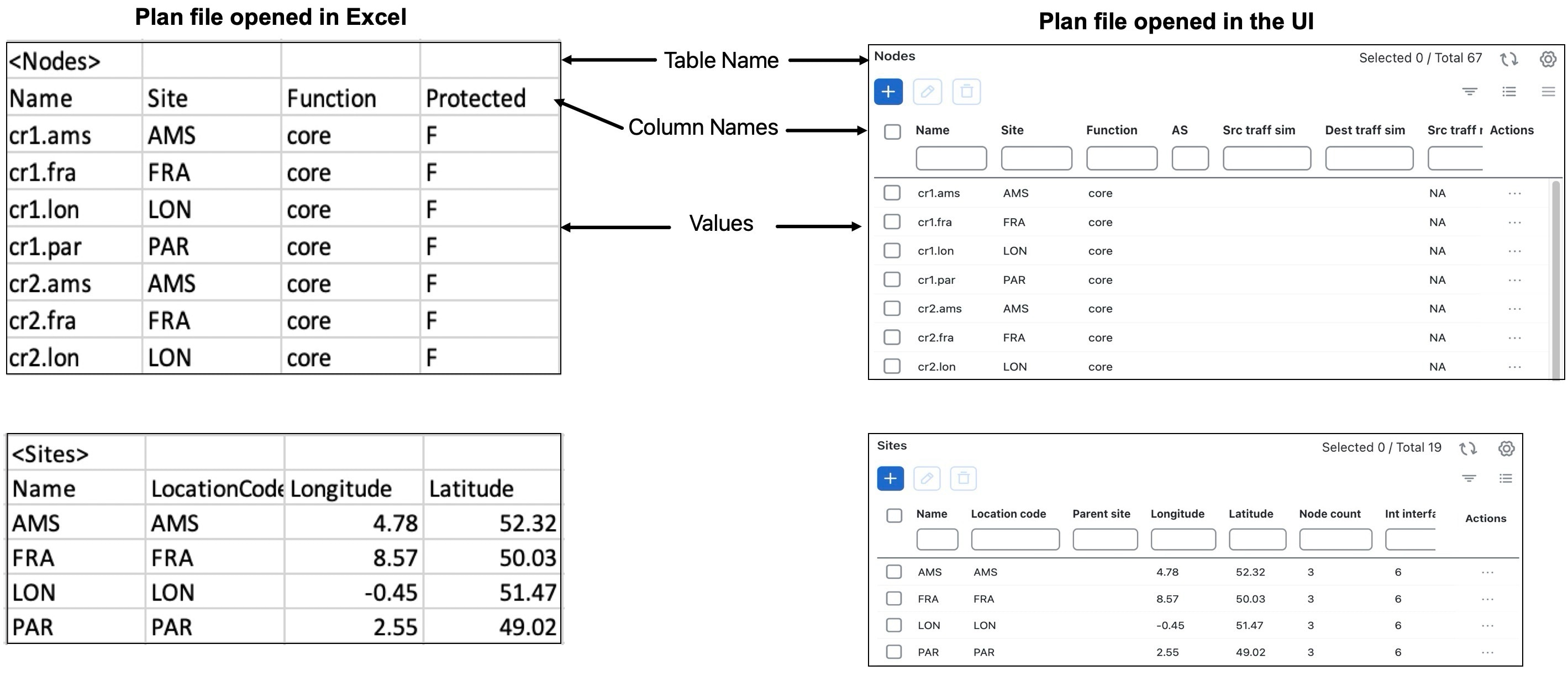
    Initially, network topology and routing information is captured by Cisco Crosswork Planning discovery tools and stored in plan files. These plan files are the basis of information displayed in and used by Cisco Crosswork Planning.

    Plan files contain

    • network configurations

    • visual layouts

    • IP/MPLS routes, including multicast and LSPs

    • measured traffic

    • estimated end-to-end traffic matrix

    • operational state of network objects, and

    • results of analyses, such as worst-case failure analysis results.

    Plan files have two formats:

    • The .pln format is compact and can be quickly loaded to and saved in the Cisco Crosswork Planning UI.

    • The .txt format contains tab-delimited columns. You can create and edit these directly in a text editor or spreadsheet, such as Excel, and quickly apply bulk edits. In these plan files, each table is labeled with angle brackets, such as <Nodes> and <Sites>.

  • Plan Objects: Other than a site, an object is a representation of elements found in networks, such as nodes (which represent routers), circuits, interfaces, LSPs, and more. A site is also an object, and is a Cisco Crosswork Planning construct for simplifying the visualization of a network by grouping nodes within a site, or even by grouping sites within a site.

    For more information, see Understand Plan Objects.

  • Design Engines: Design Engine in Cisco Crosswork Planning serves as the brain performing all simulations and optimizations. It allows to perform tasks interactively as synchronous or as an asynchronous job. When the user logs in and wants to open a plan file, an engine is assigned to the user session (subject to engine availability). Once an engine is assigned, this engine is responsible for handling all user real-time activities. You can open a maximum of three plan files in parallel. Each plan file is maintained individually in the form of a network model. Only one network model is active at any given time. You can switch the active network model among all opened network models and all activities are applied to the active network model only.

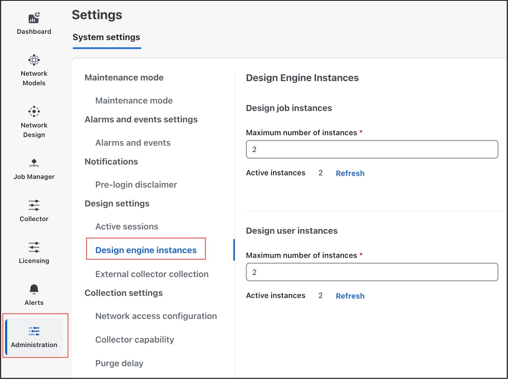
    • Engine Spaces: Engines can be run in two spaces: user space and job space. Each space operates independently and can only use the assigned resources. For more information, see Allocate Design Engine Instances.

      Each engine runs on the same version of the image. However, depending on the space it operates in user space or job space, it operates in synchronous mode or asynchronous mode, respectively.

    • Synchronous Mode: When the Cisco Crosswork Planning engine operates in user space, it is in synchronous mode. It can handle user requests interactively and provide results in real time.

    • Asynchronous Mode: When the Cisco Crosswork Planning engine operates in job space, it is in asynchronous mode. Depending on computation complexity, few operations may take a longer time to complete a request. These operations are submitted as jobs and the engines running in job space process these job requests. These jobs run in the background, without affecting the other user activities.

      The engine in asynchronous mode processes every assigned tasks independently. After a job is complete, it saves the results as .tar files in the Job Manager. You can download and extract this .tar file, and then import the updated file into the user space.

  • Patch Files: A patch file is a compact way to represent the differences between plan files. These differences or “patches” can be applied to other plan files or deployed to the network. Patch files have a .plp format.

    For information on creating and applying patches, see Create and Use Patch Files.

Log In and Log Out

Cisco Crosswork Planning is a browser-based application. For details on supported browser versions, see the "Supported Web Browsers" section in the Cisco Crosswork Planning 7.0 Installation Guide.

After installing Cisco Crosswork Planning, you can access the Cisco Crosswork Planning UI using the following steps.

Procedure


Step 1

Open a web browser and enter:

https://<Crosswork Management Network Virtual IP (IPv4)>:30603/

When you access Cisco Crosswork Planning from your browser for the first time, some browsers display a warning that the site is untrusted. When this happens, follow the prompts to add a security exception and download the self-signed certificate from the server. After you do this, the browser accepts the Cisco Crosswork Planning server as a trusted site in all subsequent logins.

Step 2

The Cisco Crosswork Planning's browser-based user interface displays the login window. Enter your username and password. The default administrator user name and password is admin. This account is created automatically at installation. The initial password for this account must be changed during installation verification. Cisco strongly recommends that you keep the default administrator credential secure, and never use it for routine logins. Instead, create new user roles with appropriate privileges and assign new users to those roles. At least one of the users you create should be assigned the "administrator" role.

Step 3

Click Login.

Step 4

To log out, click in the top right of the main window and choose Logout.

Note


Logging out while working on a plan file does not result in closing of the file; it remains open.


Dashboard

After successful login, the Dashboard page opens. The Dashboard page provides an at-a-glance operational summary of Cisco Crosswork Planning. The dashboard is made up of a series of dashlets. The dashlets included in your dashboard depend on which Cisco Crosswork Planning application is installed. For example, the Collections and Archive network models dashlets are displayed only if you have installed the Cisco Crosswork Planning Collector application. The My network design models, My design jobs, and Design engine dashlets are displayed only if you have installed the Cisco Crosswork Planning Design application.

Links in each dashlet allow you to explore further details. This helps to navigate to the desired pages easily. For example, in the following image, link 2 in the Open tab in the My network design models dashlet indicates that there are two network models open in the UI. If you click this number 2, the two opened network models are displayed in the Network Design page.

Figure 2. Dashboard View

Use the Customize view button at the top right corner to customize how the dashlets appear. For details, see Customize the View of the Dashboard.

Customize the View of the Dashboard

By default, all the available dashlets appear in the Dashboard page. Use the Customize view button at the top right corner to customize how the dashlets appear. Using this option, you can:

Figure 3. Dashboard - Customize View

Rearrange Dashlets

Follow these steps to rearrange the dashlets.

Procedure

Step 1

Click the Customize view button at the top right corner. The page becomes editable.

Step 2

Drag and drop the dashlets to the position you want.

Step 3

Click Save.


Add Dashlets

By default, all the available dashlets are added in the Dashboard page. If a dashlet was removed for any reason, follow these steps to add it back.
Procedure

Step 1

Click the Customize view button at the top right corner. The page becomes editable.

Step 2

Click + Add dashlet in the last empty dashlet. The Add Dashlet window appears.

Step 3

From the list on the left side, select the dashlet you want. The preview of the dashlet is displayed by default.

Step 4

(Optional) Edit the name of the dashlet.

Step 5

Click Save.


Remove Dashlets

Follow these steps to remove the dashlets.

Procedure

Step 1

Click the Customize view button at the top right corner. The page becomes editable.

Step 2

Click Advanced Filter icon in the dashlet you want to delete. The Remove Dashlet dialog box appears.

Step 3

Click Yes.


Edit Dashlets

Follow these steps to edit the name of a dashlet.

Procedure

Step 1

Click the Customize view button at the top right corner. The page becomes editable.

Step 2

Click in the dashlet you want to edit. The Edit Dashlet dialog box appears.

Step 3

In the Dashlet title field, enter the new name of the dashlet.

Step 4

(Optional) Click Preview to preview the dashlet with new name.

Step 5

Click Save.


Copy Dashlets

Follow these steps to make a copy of a dashlet.

Procedure

Step 1

Click the Customize view button at the top right corner. The page becomes editable.

Step 2

Click in the dashlet you want to make a copy. The Copy Dashlet Confirmation dialog box appears.

Step 3

Click Copy.

A copy of the dashlet appears in the dashboard.


Reset Dashboard

To reset the dashboard to the default view, do the following:

Procedure

Step 1

Click the Customize view button at the top right corner. The page becomes editable.

Step 2

Click the Reset button at the bottom of the page.

The Reset Dashboard confirmation window appears.

Step 3

Click Reset in the confirmation window.


Allocate Design Engine Instances

For an overview of design engines, see Before You Begin.

Post installation, four design engine instances are created in the system: two instances run in synchronous mode, while the other two run in asynchronous mode. However, you have the flexibility to increase the number of design engine instances to execute multiple jobs in parallel.

In the Cisco Crosswork Planning UI, the number of design engine instances allocated for synchronous and asynchronous jobs is displayed in the Design user instances and Design job instances sections respectively. This implies that the number of concurrent users supported depends on the number of Design user instances configured. Similarly, the number of parallel background jobs is determined by the number of Design job instances configured.

Example: In large scale deployments, you may need to run multiple simulation or optimization tools simultaneously, or perform tasks on huge plan files. In such cases, increase the number of Design job instances. For example, if you set the Design job instances as 8, then eight scheduled jobs can be run in parallel. Similarly, if you want to increase the number of synchronous job instances, increase the number in the Design user instances section. For example, if you configure this number as 5, five users can run the synchronous jobs simultaneously.


Note


  • Only admin users can alter the number of allocated design engine instances.

  • You must allocate at least one engine for each of the user and job instances, and you can allocate a maximum of 10 design engines for both user and job instances combined. For details on scale numbers, see the Cisco Crosswork Planning 7.0 Installation Guide.


Follow these steps to allocate design engine instances as per your requirement.

Before you begin

Ensure that you are an admin user.

Procedure


Step 1

From the main menu, choose Administration > Settings > System settings > Design settings > Design engine instances.

The Design Engine Instances page opens.

Figure 4. Design Engine Instances

Step 2

In the Design job instances and Design user instances sections, enter the required number of design engine instances.

Make sure that the total number of allocated engines is not more than 10 and at least one engine is allocated for each user and job instances.

Step 3

Click Save.

Note


In case you increase the number of design engine instances, wait until the associated microservices become healthy. Verify this by clicking the Refresh link in the Active instances field. Ensure that the number of active instances matches the value entered in the Maximum number of instances field.


Manage User Sessions

If you are an admin user, you can free up an engine instance from a user, enabling the engine instance to be reassigned to a different user.

When a user session is ended, all open plans for the selected user are closed, and any operations triggered by the user are aborted, thereby freeing up the engine instance from the selected user. This feature also allows the admin user to reset the Cisco Crosswork Planning Design application if it becomes unresponsive or stuck due to certain operations.

Follow these steps to terminate the user session of a logged in user.


Note


You must be an admin user to perform this procedure.


Procedure


Step 1

From the main menu, choose Administration > Settings > System settings > Design settings > Active sessions.

The Active Sessions page opens displaying a list of logged-in users. Each entry indicates that a particular user is assigned or mapped to a design engine instance.

Step 2

Select the user whose session you want to terminate.

Step 3

Click Reset session.