Simulate Advanced Routing with External Endpoints

To model basic IGP routing, demands are sourced or destined for nodes within the topology. To model basic inter-AS routing, the sources and destinations are neighboring external ASes, or a combination of the external AS and the peering node in that AS. However, more complex routing situations require the use of external endpoints as the source or destination. External endpoints can contain multiple member nodes and ASes, and you can specify when traffic enters or exits from each of them individually. This allows you to simulate routing within and between ASes where multiple traffic entry and exit points are used simultaneously. You can also prioritize where the traffic fails over to other nodes and ASes.

There are numerous use cases both for IGP and inter-AS routing:

  • Simulate content caching failovers for in-network source of demands that are backed up by another in-network source. If connectivity is lost to the first, traffic is sourced from the second.

  • Simulate edge routing with a single entry point into the network edge and a specific failover point. Alternatively, you could model multiple entry points, depending on which is closest to the destination.

  • Simulate complex BGP routing policies from a transit provider. For example, you can specify a transit entry location and failover location per destination.

  • Simulate failover between peering ASes; for example, from one single-connection transit provider to another.

This section contains the following topics:

Routing with External Endpoints

An external endpoint is a Cisco Crosswork Planning object that identifies specific entry (source) or exit (destination) points for demands. These are identified in the External Endpoints table by a name.

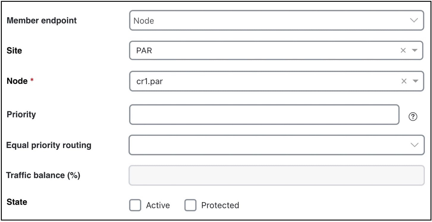
Each external endpoint consists of one or more members that are defined as nodes, external ASes, or a combination of an external AS and external node. By setting a demand’s source or destination to an external endpoint, you can simulate traffic going from multiple sources to a single destination, from a single source to multiple destinations, or multiple sources going to multiple destinations. Because of this flexibility, they are useful for specifying secondary entry and exit points in the event of failures.

Create External Endpoints and their Members

The recommended method of creating external endpoint members is to do so while creating the associated external endpoint, as follows:

Procedure


Step 1

Open the plan file (see Open Plan Files). The plan file opens in the Network Design page.

Step 2

From the toolbar, choose Actions > Insert > Demands > External endpoints.

OR

In the Network Summary panel on the right side, click Add icon in the External endpoints tab.

The External endpoints tab is available under the More tab. If it is not visible, then click the Show/hide tables icon (Show/Hide Tables Icon) and check the External endpoints check box.

Step 3

In the Name field, enter a unique external endpoint name.

Step 4

To add a new member, click Add icon. To edit an existing member, select it from the Members table and click Edit icon.

An External Endpoint Member window opens (see External Endpoint Members). Specify the parameters as described in Specify External Endpoint Members and click Add.

Step 5

Click Add in the Add External Endpoint window.


Specify External Endpoint Members

Each member is assigned properties that prioritize traffic entering and exiting that member, in which order to fail over to another member, and how to distribute traffic for members of equal priority. These properties are set when you create the member, and all members are listed in the External endpoint members table. For details on creating External endpoint members, see Create External Endpoints and their Members.

Figure 1. External Endpoint Members
  • Member endpoint—Defines whether the member is a node, AS, or external node via an AS.

    • For nodes, choose the site and node name.

    • For interfaces, choose the site, node, and interface. Using an interface lets you specify the exact interface on which the demand traffic is going into or out of a node.

    • For ASes, choose the AS name, and select either the “(None)” option or node name within the AS. The “(None)” option routes traffic evenly throughout the entire AS.

  • Priority—The sequential order in which external endpoint members are used in the simulations should failures occur.

  • Equal priority routing—If members have the same priority, this property identifies how the traffic is distributed. Choose from the following options, as required:

    • Shortest Path—Use the member that results in the use of shortest path between source and destination.


      Note


      Members within an external endpoint that have the same priority must either all be Shortest Path or none of them be Shortest Path.

      If a member is using the shortest path, the Traffic balance (%) field is displayed as disabled.

    • Fix Traffic—Set the traffic across members of equal priority as defined in the Traffic balance (%) field.

    • Deduce Traffic—Behaves the same as Fix Traffic in that it sets traffic across members of equal priority as defined in the Traffic balance (%) field. However, upon running the Demand deduction tool, the Traffic balance (%) field is updated based on the measured traffic in the network. Note that Demand deduction only estimates the traffic balances for external endpoints with a priority that is in use in the current no-failure simulation. Thus, Deduce Traffic is usually set to Priority 1.

Simulate Routing


Note


Although this section describes demands as being sourced from an external endpoint, the same methodology holds true if a demand’s destination is an external endpoint.

If a demand’s source is defined as an external endpoint, the following selection of external endpoint members ensues.

Procedure


Step 1

Members with the highest priority (lowest number) are used as the demand’s source. For example, if the external endpoint has two members with a priority of 1, the demand is sourced from both members provided they are available.

If one or more of the members are not available, the traffic from the unavailable members is evenly redistributed to the other top priority members.

Step 2

If none of the top priority members are available to source the traffic but there are next-priority members available, Step 1 is repeated for the next priority external endpoint members. Only if all members with the same priority fail does the traffic get routed according to the next priority in the sequence.

Note that if a failure occurs that does not affect the external endpoint member’s ability to send or receive traffic, then traffic is rerouted as usual without a need to use the additional members.

If an external endpoint member is an external AS, with or without a node specified, then the routing from or to that member is determined by the BGP routing policy determined by the AS relationships. The distribution of traffic between external endpoints with the same priority is the same as that for node members.


Traffic Distribution

The traffic distribution through these demands is based on the Equal priority routing property, and if applicable, the Traffic balance (%) property is used to define the external endpoint members.

  • If there is only one member and it is defined as Shortest Path, the demand takes the shortest path as defined by the IGP metrics.

Of the routable demands, if the Traffic balance (%) values are all empty, the traffic is routed and equally load balanced across the demands with the shortest IGP paths. Note in the case of multiple internal ASes, the shortest IGP route is the shortest route in the first AS the demand enters.

  • If multiple members of the same priority are set to Shortest Path, the demand takes the path with the shortest IGP path. If all interfaces between the source members and the destination have the same shortest IGP paths, then the traffic is load balanced equally across them.

  • If one or more members of the same priority have their Equal priority routing property set to Fix Traffic or Deduce Traffic, the demand traffic is split according to each member’s Traffic balance (%) value.

    • If the Traffic balance percentages across sources with the same priority sum to less than 100%, the overall demand traffic is decreased to that percentage.

    • If an external endpoint member of the same priority fails, the traffic on the remaining members increases in proportion, so that the same amount of traffic is still routed.

Example: Node A failed. Nodes B, C, and D each have a priority of 2 and are each a Fix Traffic type. Their traffic balances are 20%, 20%, and 40%, respectively. The demand has 1000 Mbps of traffic.

  • Because Node A failed, the demand routes 200 Mbps traffic through node B, 200 Mbps through C, and 400 Mbps through D, totaling 800 Mbps.

  • If Node D fails, the demand routes 400 Mbps traffic through Node B and 400 through C. If Node B fails too, the entire 800 Mbps is routed through C.

  • If all three priority 2 members fail, 1000 Mbps is routed through node E, which is the priority 3 member.