This document describes how to create, provision, and visualize SR policies using Crosswork Network Controller.
This document contains the following sections:
Overview of Transport Services in Crosswork Network Controller
Crosswork Network Controller enables provisioning of segment routing (SR) policies for services with explicit SLAs by specifying optimization objectives (latency/IGP/hopcount/TE metric minimization) and constraints (affinities, disjoint paths, bandwidth). A segment routing policy path is expressed as a list of segments that specifies the path, called a segment ID (SID) list. Each segment is an end-to-end path from the source to the destination, and instructs the routers in the network to follow the specified path instead of the shortest path calculated by the IGP. If a packet is steered into an SR policy, the SID list is pushed on the packet by the head-end. The rest of the network executes the instructions embedded in the SID list.
For more information about segment routing, see Segment Routing Basics.
-
Explicit: Uses an explicit path which consists of a list of prefix or adjacency Segment IDs (SID list), each representing a node or link along on the path.
-
Dynamic: Uses a dynamic path based on an optimization objective and a set of constraints. The head-end computes a path, resulting in a SID list or a set of SID lists. When the topology changes, a new path is computed.
-
On-Demand Next Hop (ODN): Allows a service head-end router to automatically instantiate an SR policy to a BGP next-hop when required (on-demand).
-
Bandwidth on Demand: A dynamic path steering policy that finds the optimal path when a persistent bandwidth is required.
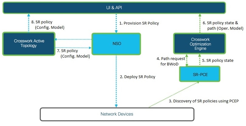
SR Policy Discovery and Provisioning
SR policies and Layer 3 links configured in the network are discovered by the SR-PCE component. Discovered SR policies can be visualized and monitored in the Optimization Engine area of Crosswork Network Controller.
SR policies can be provisioned in the Provisioning area of the Crosswork Network Controller UI. Provisioning is executed by the underlying NSO component.
Where to Find SR Policies in the UI
 Note |
Optimization Engine does not show named SR policies that were provisioned using Crosswork Network Controller. |
To see a table of provisioned SR policies: From the main menu, go to . You can select SR policies in the table to visualize them on the topology map and you can drill down to additional details.
Note |
Active Topology shows SR policies provisioned by Crosswork Network Controller ONLY. It does not show the SR policies discovered by SR-PCE from the network. |
See Visualize SR Policies Discovered from the Network and Visualize Provisioned SR Polices from Active Topology.
-
Config View: Shows the configuration of the policy.
-
View in Optima: Cross-launches to the Optimization Engine area where you can visualize the policy on the topology map. This option is not available for ODN Template policies
-
Edit: Allows you to edit the policy and recommit your changes.
-
Delete: Allows you to delete the policy.
Segment Routing Basics
Resource Reservation Protocol (RSVP) is a protocol that you are most likely familiar with. It is a signaling protocol that enables systems to request resource reservations from the network. RSVP processes protocol messages from other systems, processes resource requests from local clients, and generates protocol messages. As a result, resources are reserved for data flows on behalf of local and remote clients. RSVP creates, maintains, and deletes these resource reservations. This section focuses on a high-level overview of Segment Routing (SR) which is gaining popularity in the networking routing area.
Segment routing is a method of forwarding packets on the network based on the source routing paradigm. The source chooses a path and encodes it in the packet header as an ordered list of segments. Segments are an identifier for any type of instruction. For example, topology segments identify the next hop toward a destination. Each segment is identified by the segment ID (SID) consisting of a flat unsigned 32-bit integer.
Segments
Interior gateway protocol (IGP) distributes two types of segments: prefix segments and adjacency segments. Each router (node) and each link (adjacency) has an associated segment identifier (SID).
-
A prefix SID is associated with an IP prefix. The prefix SID is manually configured from the segment routing global block (SRGB) range of labels, and is distributed by IS-IS or OSPF. The prefix segment steers the traffic along the shortest path to its destination. A node SID is a special type of prefix SID that identifies a specific node. It is configured under the loopback interface with the loopback address of the node as the prefix.
A prefix segment is a global segment, so a prefix SID is globally unique within the segment routing domain.
-
An adjacency segment is identified by a label called an adjacency SID, which represents a specific adjacency, such as egress interface, to a neighboring router. The adjacency SID is distributed by IS-IS or OSPF. The adjacency segment steers the traffic to a specific adjacency.
An adjacency segment is a local segment, so the adjacency SID is locally unique relative to a specific router.
By combining prefix (node) and adjacency segment IDs in an ordered list, any path within a network can be constructed. At each hop, the top segment is used to identify the next hop. Segments are stacked in order at the top of the packet header. When the top segment contains the identity of another node, the receiving node uses equal cost multipaths (ECMP) to move the packet to the next hop. When the identity is that of the receiving node, the node pops the top segment and performs the task required by the next segment.
Segment Routing for Traffic Engineering
Segment routing for traffic engineering takes place through a tunnel between a source and destination pair. Segment routing for traffic engineering uses the concept of source routing, where the source calculates the path and encodes it in the packet header as a segment. Each segment is an end-to-end path from the source to the destination, and instructs the routers in the provider core network to follow the specified path instead of the shortest path calculated by the IGP. The destination is unaware of the presence of the tunnel.
Segment Routing Policies
Segment routing for traffic engineering uses a “policy” to steer traffic through the network. An SR policy path is expressed as a list of segments that specifies the path, called a segment ID (SID) list. Each segment is an end-to-end path from the source to the destination, and instructs the routers in the network to follow the specified path instead of the shortest path calculated by the IGP. If a packet is steered into an SR policy, the SID list is pushed on the packet by the head-end. The rest of the network executes the instructions embedded in the SID list.
There are two types of SR policies: dynamic and explicit.
Dynamic SR PolicyA dynamic path is based on an optimization objective and a set of constraints. The head-end computes a solution, resulting in a SID list or a set of SID lists. When the topology changes, a new path is computed. If the head-end does not have enough information about the topology, the head-end might delegate the computation to a path computation engine (PCE).
Explicit SR PolicyWhen you configure an explicit policy, you specify an explicit path which consists of a list of prefix or adjacency SIDs, each representing a node or link along on the path.
Disjointness
Crosswork Network Controller uses the disjoint policy to compute two lists of segments that steer traffic from two source nodes to two destination nodes along disjoint paths. The disjoint paths can originate from the same head-end or different head-ends. Disjoint level refers to the type of resources that should not be shared by the two computed paths. The following disjoint path computations are supported:
-
Link – Specifies that links are not shared on the computed paths.
-
Node – Specifies that nodes are not shared on the computed paths.
-
SRLG – Specifies that links with the same Share Risk Link Group (SRLG) value are not shared on the computed paths.
-
SRLG-node – Specifies that SRLG and nodes are not shared on the computed paths.
When the first request is received with a given disjoint-group ID, a list of segments is computed, encoding the shortest path from the first source to the first destination. When the second request is received with the same disjoint-group ID, information received in both requests is used to compute two disjoint paths: one path from the first source to the first destination, and another path from the second source to the second destination. Both paths are computed at the same time. The shortest lists of segments is calculated to steer traffic on the computed paths.
Note |
|
Visualize SR Policies
Crosswork Network Controller provides a real-time graphical, topological map view of the devices and links in your network and allows you to visualize SR tunnels as an overlay on the map for easy monitoring and management.
Visualize SR Policies Discovered from the Network
This topic describes the Optimization Engine topology map in which SR polices discovered from the network by SR-PCE can be visualized. Visualization of SR policies created and provisioned from the Provisioning area of Crosswork Network Controller, i.e., through the NSO component, begins in the Active Topology area. From there you can drill down to details and visualization of participating SR polices. The basic functionality of the maps in both areas is the same. The overlays of SR policies in the two maps show different levels of detail.
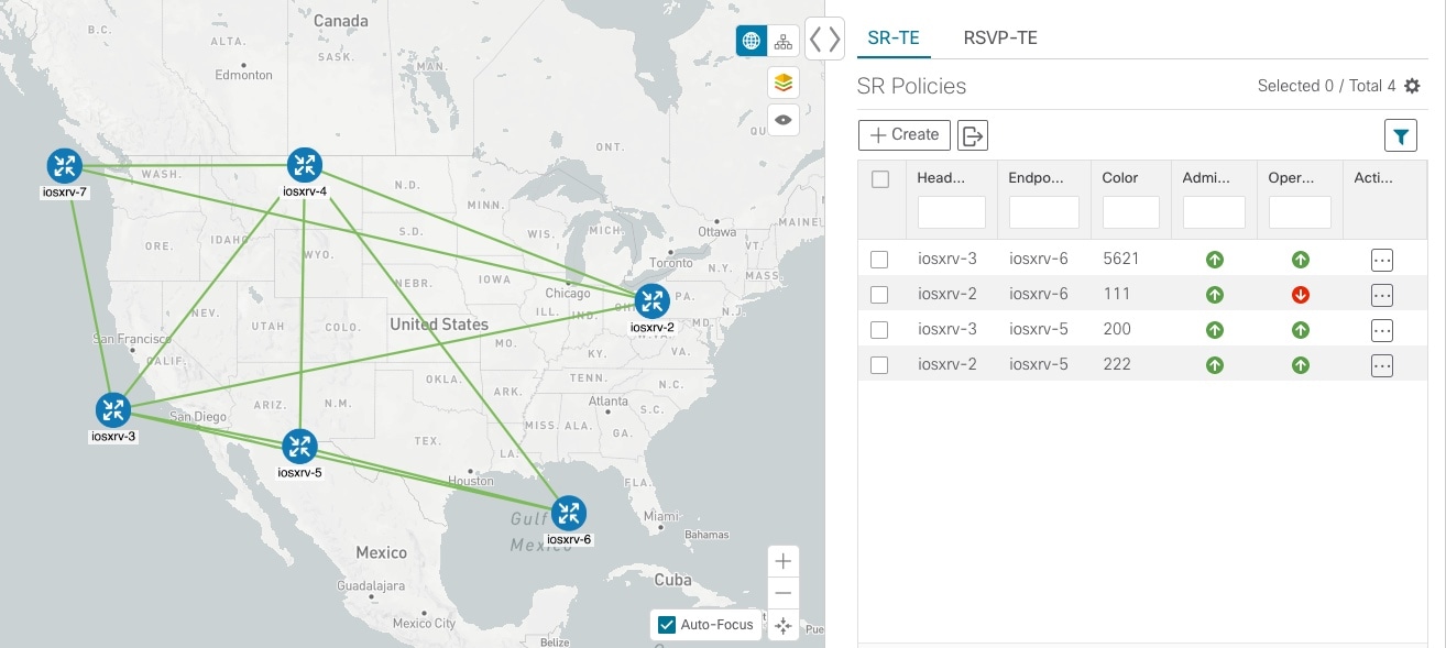
Follow the steps in this example to quickly familiarize yourself with a number of TE tunnel visualization features that are available from the topology map.
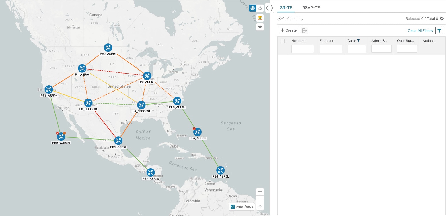
In this example, we are using the following geographical map with devices and links that have SR policies configured. SR policies are not yet highlighted in the map.
Procedure
| Step 1 |
From the SR Policies table, click the checkbox next to the SR policies you are interested in. In this example, there are two SR policies selected. 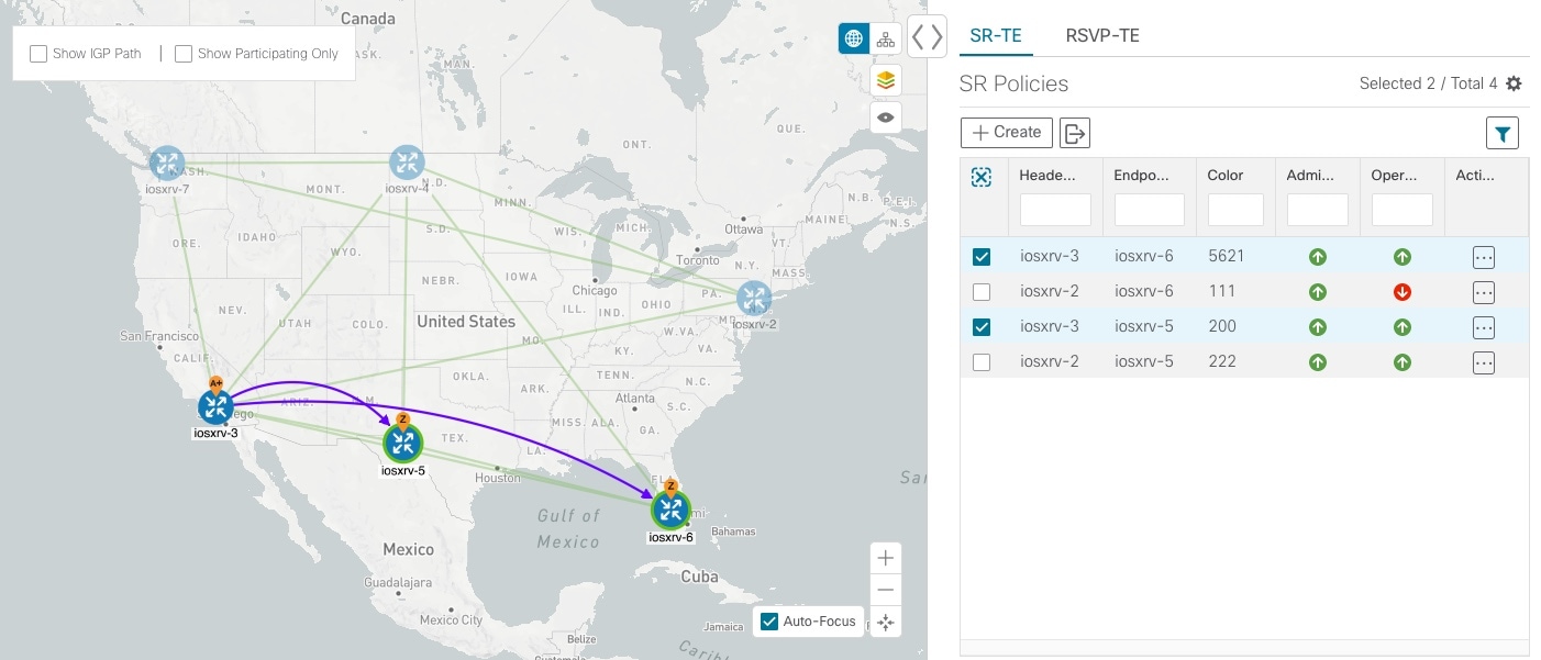
After SR policy selection, the map displays the following:
|
||
| Step 2 |
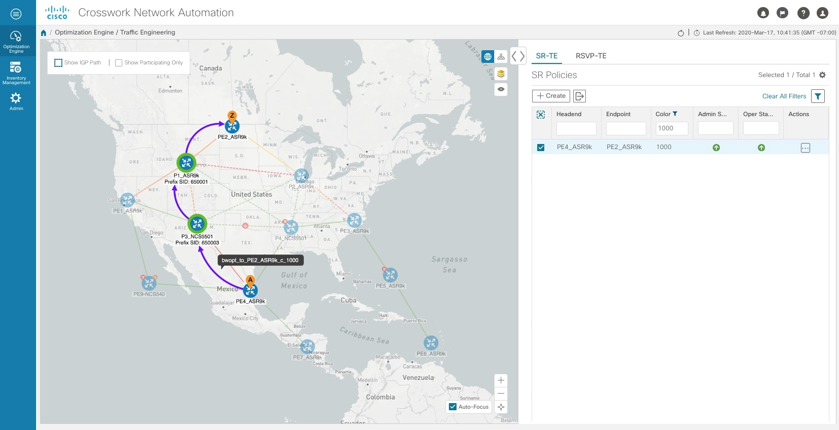
From the SR Policies table, hover over a selected policy. The path name of that policy is highlighted on the topology view. You will also see prefix SID information. 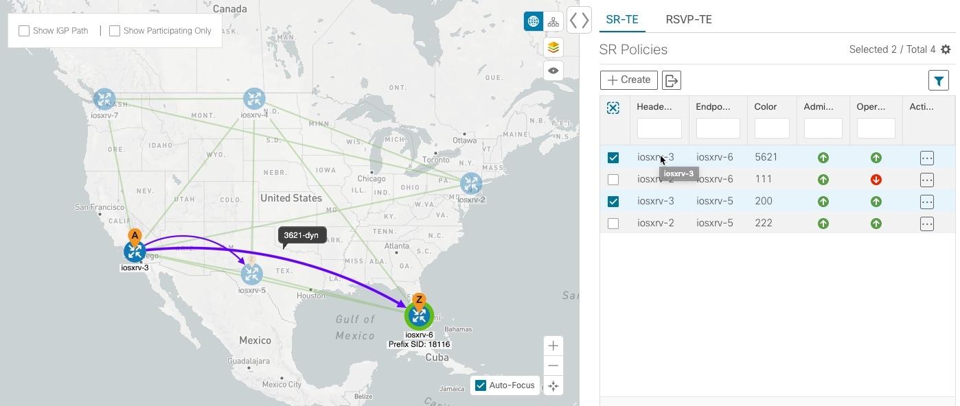
|
||
| Step 3 |
Check the Show IGP Path check box (available only with SR policies). The IGP paths for the selected SR policies are displayed, with straight lines, instead of the segment hops. 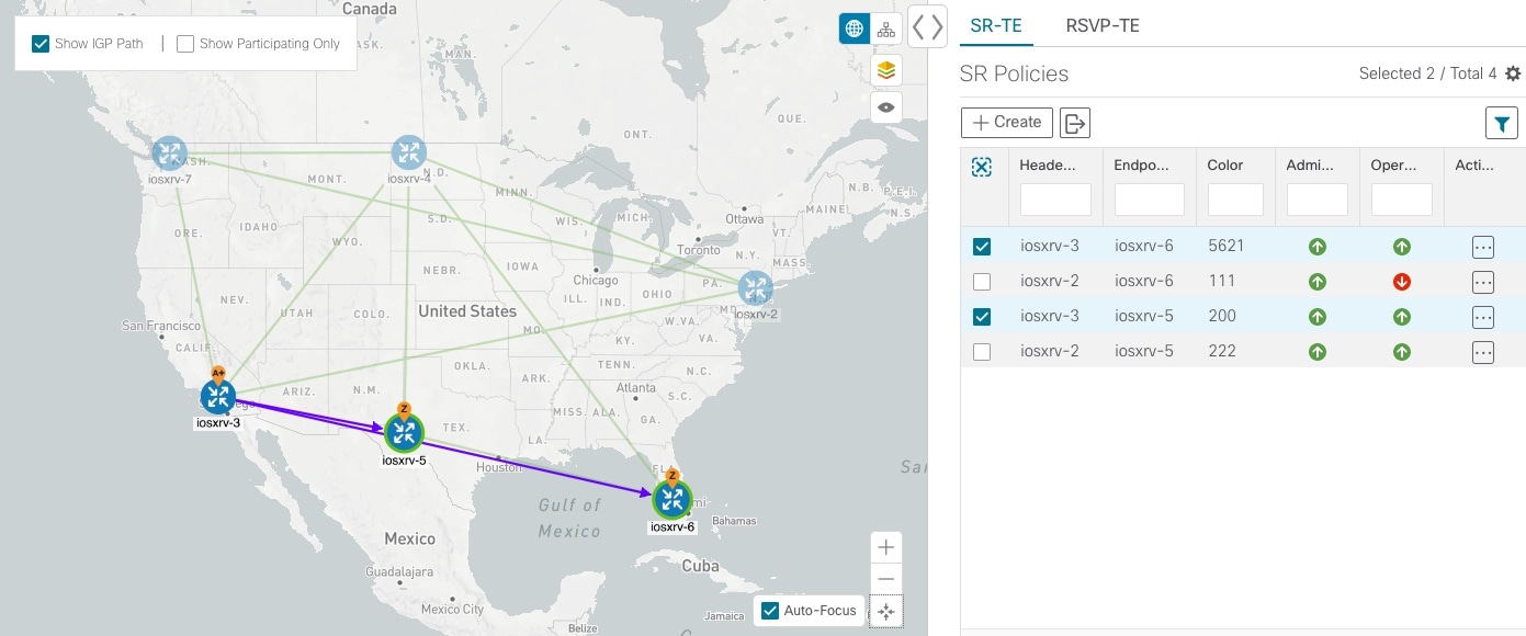
|
||
| Step 4 |
Check the Show Participating Only check box. All non-participating links and devices disappear. Only participating policies are displayed. 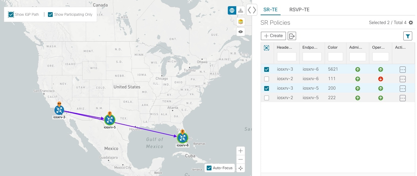
|
||
| Step 5 |
To view the IGP, TE or Delay metrics for each tunnel along a policy's path, do the following:
The metric details are displayed for each policy on the map. 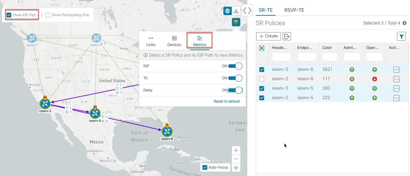
|
||
| Step 6 |
Click the logical map icon ( 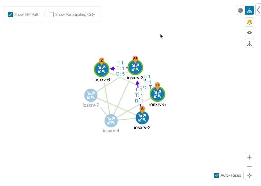
You are able to see the same information (aside from geographical
location) that is available on the geographical topology map. You also have the
ability to move devices and links on the map to make it easier to
view.
|
||
| Step 7 |
To view SR policy details such as disjoint groups, metric type, segment hop
information, and so on, click |

Note |
To return to the SR Policies table, close ( |
Troubleshoot Network Topology Map
If you encounter topology issues, such as topology components not rendering as expected or component data not displaying on the map, Cisco recommends the following:
-
If you cannot see geographical map tiles: Make sure your browser has Internet connectivity to your selected geographical map services vendor. The map services vendor and the vendor's URL are set by the system administrator.
-
If your devices are missing or appearing in the wrong location in the geographical map: If longitude and latitude values are not set the devices will default to a location off the west coast of Africa. To get your devices to display in the correct location enter the proper longitude and latitude data either via the UI or via a CSV import.
-
If you are having intermittent problems displaying the map or your devices: Clear your browser cache and try again.
Visualize Provisioned SR Polices from Active Topology
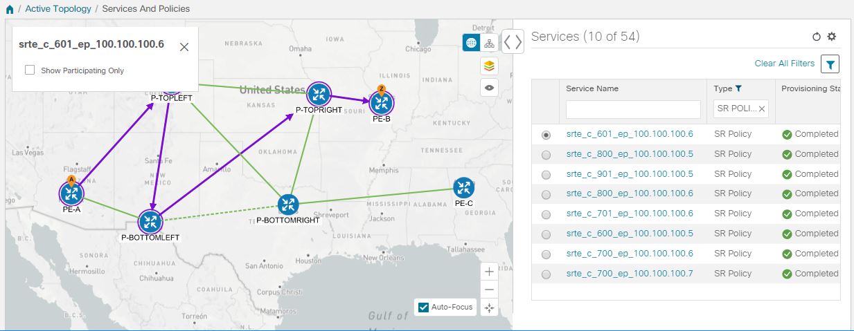
The Active Topology area contains a topology map and a list of VPN services and SR policies that were created using the Crosswork Network Controller GUI (Provisioning area) or API, and provisioned by the underlying NSO component.
Note |
If the headend and tailend devices are identified, a full overlay will be shown. If only the headend device is identified, only the headend is circled in the map. Go to Optimization Engine to visualize the SR policies associated with that headend device. See Visualize SR Policies Discovered from the Network for more information. |
The procedure below describes visualization of an explicit SR policy.
To visualize an SR policy in Active Topology:
Procedure
| Step 1 |
In the main menu, select . |
| Step 2 |
Select the required SR policy in the table on the right. The path will show as an overlay on the map, with the A-side and Z-side
devices clearly marked and arrows denoting the direction of the path:
|
| Step 3 |
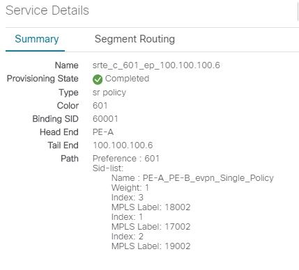
To get additional details, click The Service Details page is displayed in the side panel and shows a summary
of the policy's properties.
|
| Step 4 |
Go to the Segment Routing tab. Under Participating Policies, the table lists all SR policies in the network
that are instantiated on the headend device.
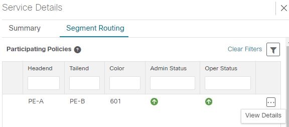
This image is not available in preview/cisco.com |
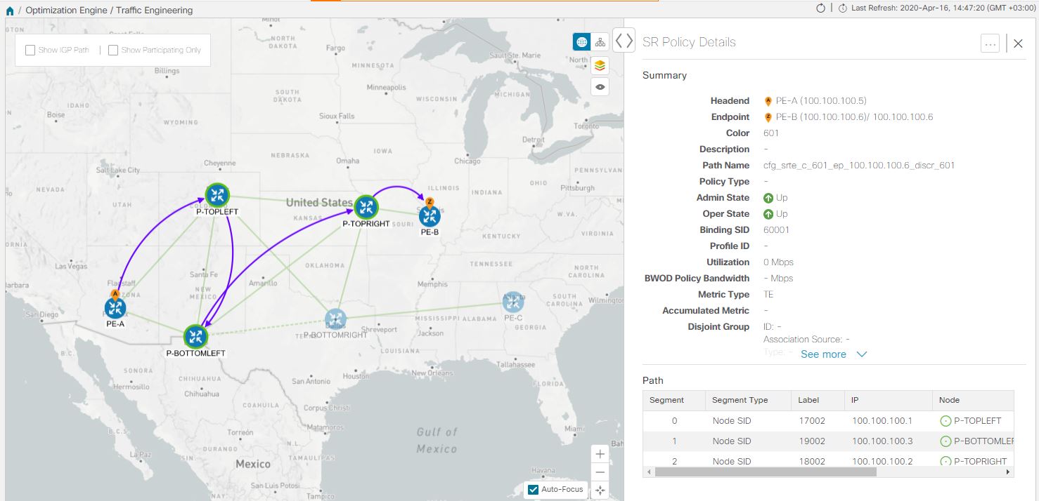
| Step 5 |
Select the required SR policy, click The view switches to Optimization Engine. Full SR Policy details are shown in
the side pane and the selected SR policy is shown as an overlay in the map.
See Visualize SR Policies Discovered from the Network for more details.
|
Bandwidth Optimization Example
Note |
There are some limitations to bandwidth optimization functionality that you should be aware of. See Important Notes and Limitations for BWOpt. |
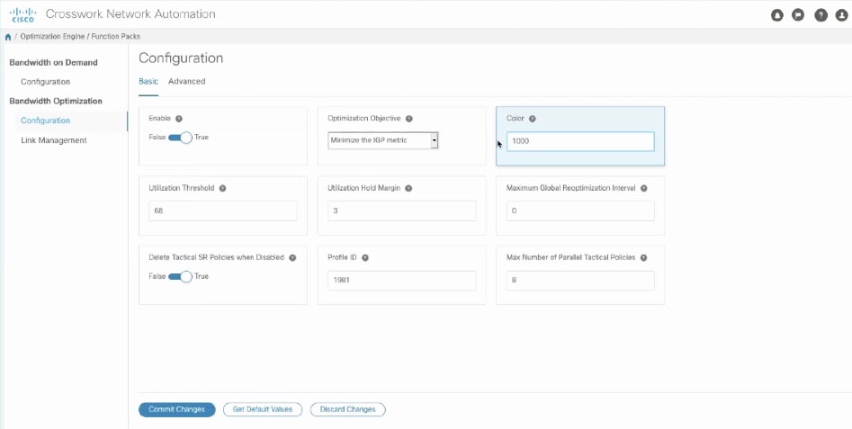
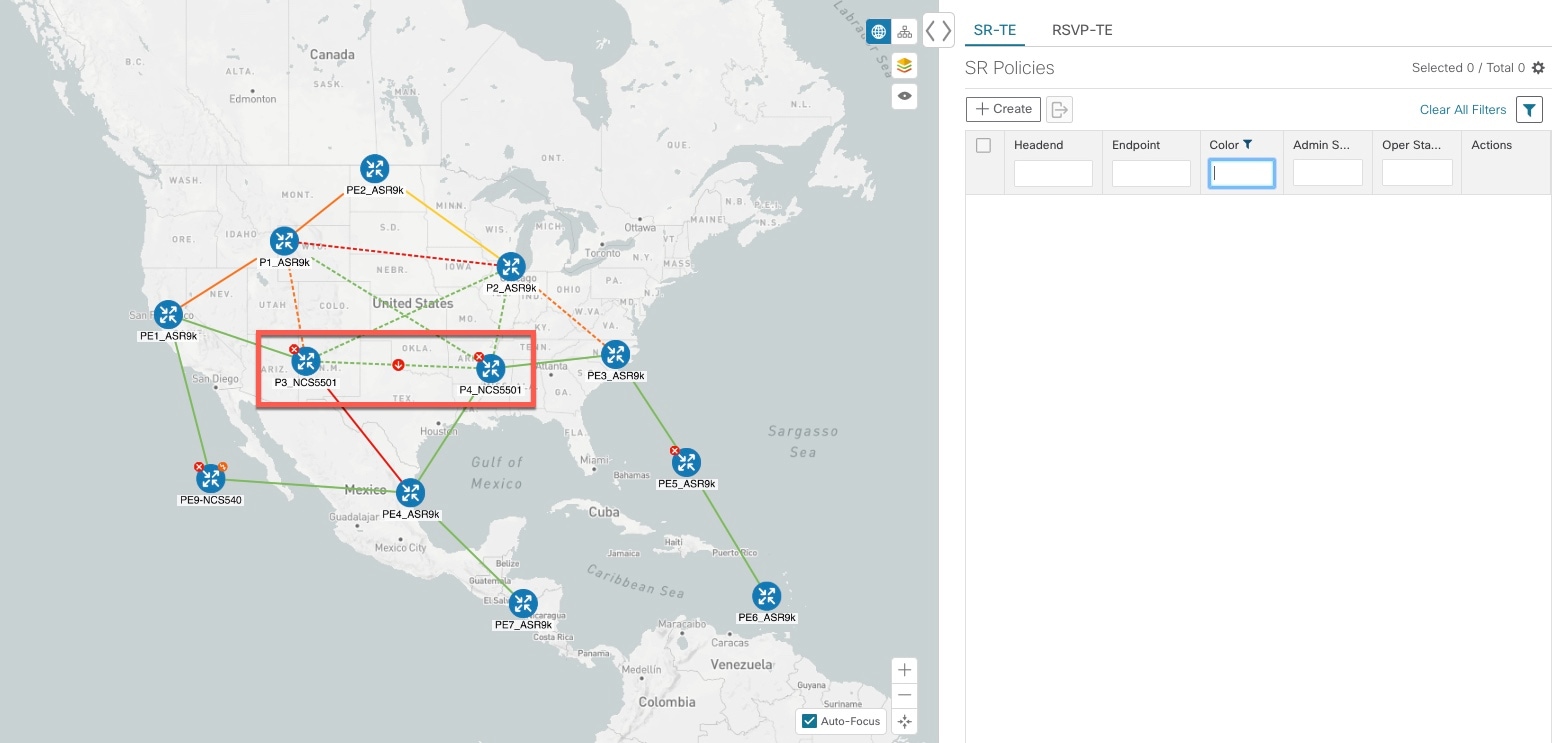
Crosswork Network Controller continually monitors the network. When the links between P3_NCS5501 and P4_NCS5501 are back up, Crosswork Network Controller will detect that the congestion (based on the defined criteria) has been mitigated. When the congestion falls under the set utilization threshold minus the utilization hold margin, the tactical SR policy is automatically removed from the network.
Important Notes and Limitations for BWOpt
Consider the following notes and limitations when using BWOpt:
-
Only traffic that is not in an SR policy or existing BWOpt SR policy can be rerouted to mitigate congested links. BWOpt will not shift traffic in existing SR policies that it did not create. This may prevent it from being able to mitigate congestion if most of the traffic on the congested link is in non-BWOpt SR policies.
-
BWOpt relies on the PCC's autoroute feature to steer traffic into the tactical SR policies it creates. Autoroute is applied to these policies through the proper Profile ID option set in BWOpt (to align with configuration on the PCC associating that Profile ID with autoroute feature). This is critical to tactical SR policies shifting traffic away from congested links.
-
BWOpt does not support multi-area or multi-level IGP. Autoroute will not properly steer traffic onto inter-area or inter-level tactical SR policies. So, although they can be provisioned, traffic will not use them. Therefore, BWOpt will be ineffective if enabled in this environment.
-
BWOpt uses simulated traffic based on measured SRTM data to determine link utilizations and when to mitigate congestion. The simulated interface utilization that BWOpt monitors should closely align with the SNMP-based interface utilization that is displayed in the UI. However, due to various factors, including SNMP polling cadence and rate averaging techniques, they may differ at times. This can result in scenarios like a link appearing to be congested in the UI and BWOpt not reacting.
-
BWOpt only creates tactical SR policies on PCCs that are sources of SRTM telemetry data. Only these nodes (typically provider edge routers) provide the telemetry-based data needed to create simulated traffic demands in the internal model representing the traffic from that node to other PE nodes in the network.
-
Only solutions that produce interface utilization below the threshold (set across all interfaces) will be deployed. If BWOpt is unable to mitigate congestion across the entire network, it will not deploy any tactical SR policies and a “Network Congested. BWOpt unable to mitigate.” alarm is set. This alarm is unset when congestion either subsides on its own or can be addressed successfully through BWOpt tactical SR policy deployments.
-
BWOpt temporarily pauses operation whenever the system is unavailable due to a restart or a rebuild of the topology from Topology Services. When this occurs, an alarm indicating this condition is set by BWOpt. During this time, BWOpt will not evaluate congestion in the network. All currently deployed tactical SR policies are maintained, but will not be modified or deleted. As soon as the model becomes available, the alarm is cleared and BWOpt will resume normal operation.
Get More Information About an SR Policy
-
In the Services table, locate the SR policy you are interested in. Under the Actions column, click
 and select View Details.
-
In the Service Details pane, the Summary tab shows the basic properties of the SR policy. Click on the Segment Routing tab to see all the participating SR policies, i.e., the policies in the network that are associated with your selected SR policy.
-
Click
next to the required policy and select View
Details. The SR Policy Details window appears. It provides
more detailed information about the policy and its associated paths. See the
table below for field descriptions.
For discovered SR policies listed in the Optimization Engine area:
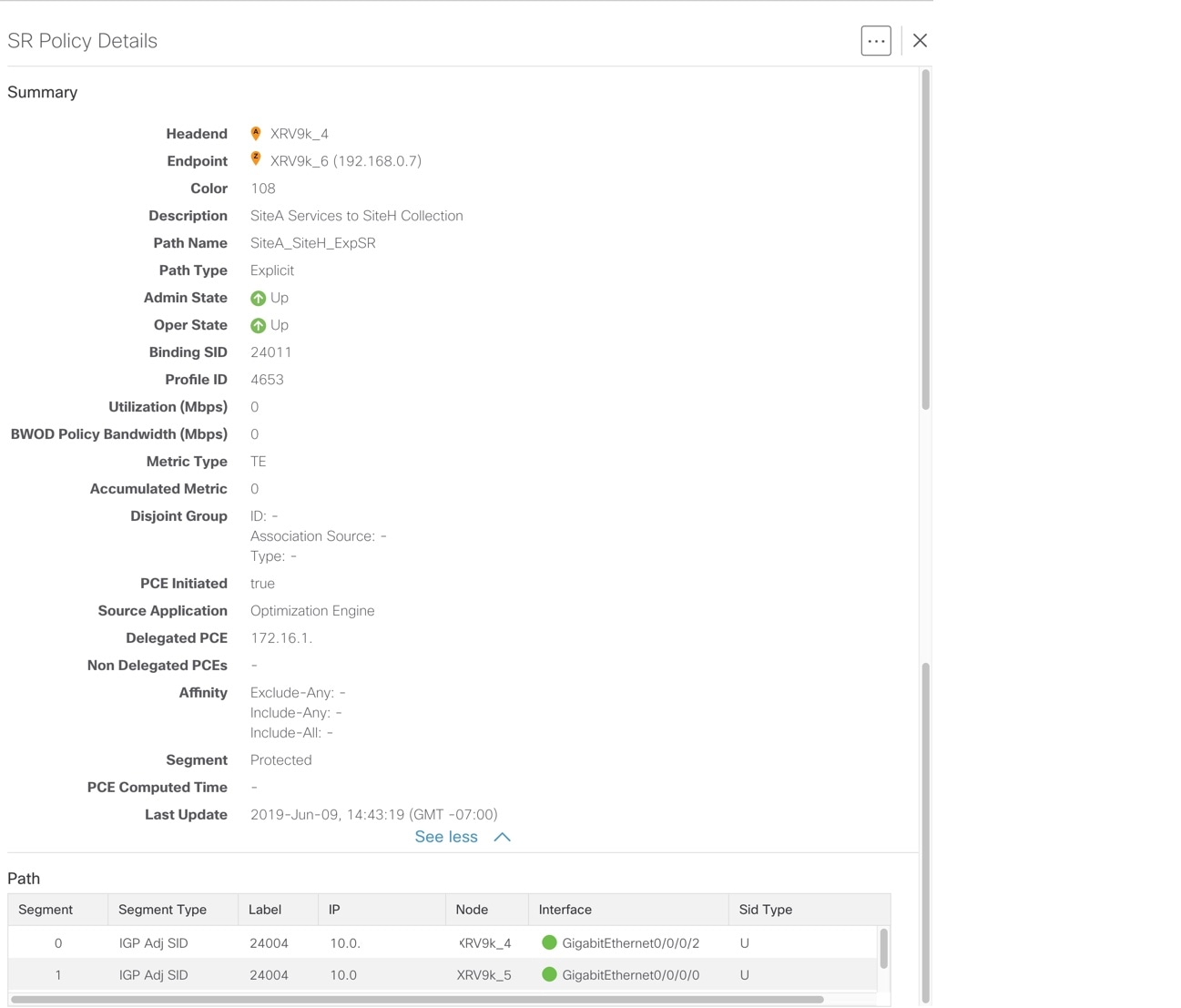
| Field | Description |
|---|---|
|
Headend |
Where the SR policy is instantiated (source). |
| Endpoint |
The destination of the SR policy. |
|
Color |
A numerical value that distinguishes between two or more policies to the same node pairs (Headend – Endpoint). Every SR policy between a given headend and endpoint must have a unique color. |
|
Description |
(Optional) If provisioned using the Crosswork Network Controller UI, it is the description entered by the user. This may be blank if the user did not enter a description. |
|
Path Name |
The name of the current active candidate path of the SR policy. For SR policies created using the Crosswork Network Controller UI, it will be the name provided by the user during configuration. For SR policies created through configuration on the headend router, the Path Name will be the base name configured for the policy on the CLI with "cfg_" appended to the beginning and the candidate path preference appended to the end. |
|
Policy Type |
Indicates whether an SR policy created through Crosswork Network Controller is explicit or dynamic. |
|
Admin State |
Administrative state is dictated by the user. For example, the user creates an SR policy and does not intentionally shut it down. The Admin State will be UP. |
|
Oper State |
Operational state received by the system. For example, the user has configured a policy and so the Admin State is UP. However, due to network issues it is operationally down. In this case, Oper State will display DOWN and Admin State will remain as UP. |
|
Binding SID |
The binding segment is a local segment identifying an SR policy. Each SR policy is associated with a binding segment ID (BSID). The BSID is a local label that is automatically allocated (or explicitly entered during manual provisioning) for each SR policy when the policy is instantiated. |
|
Profile ID |
Identification used to associate an SR policy with a set of features applied to the policy by the headend. It should correspond with a profile configured on the headend. |
|
Utilization (Mbps) |
The measured traffic on the SR policy. |
|
BWOD Policy Bandwidth (Mbps) |
The bandwidth constraint associated with a policy created through the Bandwidth on Demand function pack. |
|
Metric Type |
The metric type can be TE, IGP, or latency. |
|
Accumulated Metric |
Total metric calculation of the SR policy. |
|
Disjoint Group |
If applicable, displays disjointness information. |
|
PCE Initiated |
If the policy was initiated and provisioned by a PCE, the value is True. |
|
Delegated PCE |
The SR policy is delegated to this PCE IP address. |
|
Non Delegated PCEs |
PCEs reporting the policy, but not currently delegated. |
|
Affinity |
Lists any affinity constraints belonging to this policy. |
|
Segment |
Lists whether a dynamic path policy should prefer protected or require unprotected SIDs |
|
PCE Computed Time |
Time when PCE computed the path currently in effect. |
|
Last Update |
The last time the policy was updated. |
|
Path |
Lists segments that are part of the policy. It gives the following segment information: segment type, label, IP address, associated node, interface, and SID type (Protected or Unprotected). |
Provision SR Policies
Note |
We recommend using the Provisioning area only for SR policy provisioning in Crosswork Network Controller. Optimization Engine should be used for visualization purposes, not for provisioning. |
To access the Provisioning area of the UI and start creating SR policies:
Procedure
| Step 1 |
In the main menu, select . |
| Step 2 |
Under Services/Policies, choose . All existing SR policies that have been provisioned using Crosswork Network Controller are listed in the table on the right. |
| Step 3 |
Click |
| Step 4 |
Provide a unique name for the policy and click Continue. |
| Step 5 |
Define the SR policy as required. |
| Step 6 |
Click Commit Changes. |
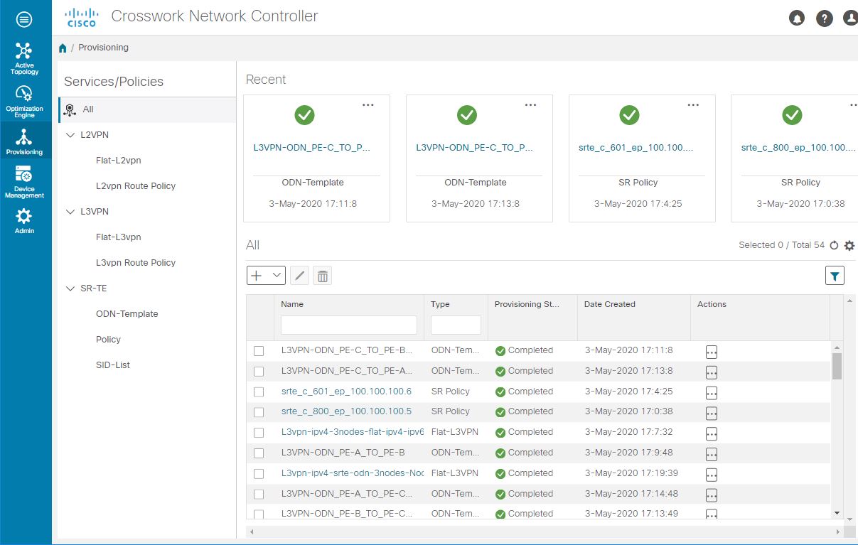
Provisioning UI Overview
In the Provisioning area of the UI, you can view a list of provisioned VPN services and SR policies and you can create/edit/delete VPN services and SR policies. You can also create supporting configurations for services and policies like SID-lists for SR policies and route policies to enable VPN services over SR ODN.
This image is not available in preview/cisco.com
-
On the left is a tree view showing the various types of supported services and SR policies, as well as underlying configurations for those services/policies, such as SID lists and route policies. Selecting a service/policy in the tree view filters the table on the right to show only services/policies of the selected type. When you first open the Provisioning area, All is selected in the tree view. The table on the right lists all provisioned L2VPN and L3VPN services and SR policies. It does not list the route policies or the SID lists.
-
The top of the Provisioning area shows the most recently provisioned services/policies, providing easy access to them for viewing their details, editing, or deleting them. To access these options, click.
Figure 20. Recent Services/Policies 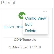
This image is not available in preview/cisco.com
-
The services/policies table lists the provisioned services/policies and shows their status. You can filter the table by name and type. The Actions column provides access to all the available actions for the selected policy, including:
-
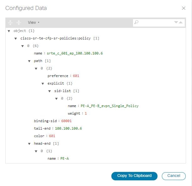
Config View: Shows the configuration of the policy.
-
Edit: Allows you to edit the policy and recommit your changes.
-
Delete: Allows you to delete the policy.
-
To see a table of provisioned VPN services and SR policies and visualize them on the map: From the main menu, go to . You can select services/policies in the table to visualize them on the topology map and you can drill down to additional details.
Create a SID List
A SID list is a list of prefix or adjacency Segment IDs, each representing a node or link along the path. Create one or more SID lists to be referenced when creating explicit SR policies. See Create Explicit Path SR Policies.
Procedure
| Step 1 |
In the main menu, select . |
| Step 2 |
Under Services/Policies, choose . All existing SID lists are listed in the table on the right. |
| Step 3 |
Click |
| Step 4 |
Provide a unique name for the SID list and click Continue. |
| Step 5 |
Click |
| Step 6 |
Enter a numeric SID index and click Continue. |
| Step 7 |
Enter either an MPLS label or an IPv4 address. |
| Step 8 |
Repeat the above procedure for additional SIDs, as required. |
| Step 9 |
Click Commit Changes. |
Create Explicit Path SR Policies
Explicit SR policies use a fixed path consisting of a list of prefix or adjacency Segment IDs (SID list), each representing a node or link along on the path.
Before you begin
Procedure
| Step 1 |
In the main menu, select . |
| Step 2 |
Under Services/Policies, choose . All existing SR policies that have been provisioned using Crosswork Network Controller are listed in the table on the right. |
| Step 3 |
Click |
| Step 4 |
Provide a unique name for the policy and click Continue. |
| Step 5 |
In the displayed form, specify the following (at minimum):
|
| Step 6 |
Define the candidate path of the SR policy:
|
| Step 7 |
Define constraints for the SR policy as required - disjoint path, affinity, segments. |
| Step 8 |
Click Commit Changes. |
| Step 9 |
Validate your SR policy creation:
|
Create Dynamic Path SR Policies
Dynamic path SR policies consist of optimization objectives and constraints that allow the head-end router to compute a SID-list that expresses the shortest dynamic path according to the selected metric type.
To create a dynamic path SR policy:
Procedure
| Step 1 |
In the main menu, select . |
| Step 2 |
Under Services/Policies, choose . All existing SR policies that have been provisioned using Crosswork Network Controller are listed in the table on the right. |
| Step 3 |
Click |
| Step 4 |
Provide a unique name for the policy and click Continue. |
| Step 5 |
In the displayed form, specify the following (at minimum):
|
| Step 6 |
Define the candidate path of the SR policy:
|
| Step 7 |
Define constraints for the SR policy as required - disjoint path, affinity, segments. |
| Step 8 |
Click Commit Changes. |
Create Bandwidth on Demand (BWoD) SR Policies
A BWoD SR policy is a dynamic path steering policy that finds the optimal path when there is a specific bandwidth requirement. It uses a bandwidth-aware Path Computation Element (PCE) to derive SR policy paths with requested bandwidth when available. Computed paths are deployed to the network through SR-PCE. Link utilization is continuously monitored to ensure no congestion occurs along the path. If conditions in the network change, causing link utilization to exceed the congestion threshold set by the user, the policy path is automatically reoptimized.
To create a BWoD SR policy:
Procedure
| Step 1 |
In the main menu, select . |
| Step 2 |
Under Services/Policies, choose . All existing SR policies that have been provisioned using Crosswork Network Controller are listed in the table on the right. |
| Step 3 |
Click |
| Step 4 |
Provide a unique name for the policy and click Continue. |
| Step 5 |
In the displayed form, specify the following (at minimum):
|
| Step 6 |
Enter the required persistent Bandwidth in kbps. |
| Step 7 |
Define the candidate path of the SR policy:
|
| Step 8 |
Click on pce to turn the pce control on and delegate the dynamic path computation to the PCE. |
| Step 9 |
Define constraints for the SR policy as required - disjoint path, affinity, segments. |
| Step 10 |
Click Commit Changes. |
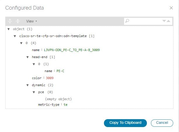
Create On-Demand Next Hop (ODN) Templates
Segment Routing On-Demand Next Hop (ODN) allows a service head-end router to automatically instantiate an SR policy to a BGP next-hop when required (on-demand). The headend is configured with an ODN template for a specific color that provides the device with the steps to follow if a route with that color appears, for example, a Layer 3 VPN route.
To create an ODN template:
Procedure
| Step 1 |
In the main menu, select . |
| Step 2 |
Under Services/Policies, choose . All existing ODN templates that have been provisioned using Crosswork Network Controller are listed in the table on the right. |
| Step 3 |
Click |
| Step 4 |
Provide a unique name for the ODN template and click Continue. |
| Step 5 |
In the displayed form, specify the following (at minimum):
|
| Step 6 |
Under dynamic, click on Enable dynamic to turn the control on. |
| Step 7 |
Select the metric type. |
| Step 8 |
Define constraints for the ODN template as required - disjoint path, affinity, segments. |
| Step 9 |
Click Commit Changes. |
| Step 10 |
Validate your ODN template creation:
|
 Feedback