-
- Downstream Interface Configuration
- Upstream Interface Configuration
- DOCSIS Interface and Fiber Node Configuration
- Service Group Based Configuration of the Cisco cBR Router
- DOCSIS Load Balancing Groups
- DOCSIS Load Balancing Movements
- DOCSIS 3.0 Downstream Bonding
- DOCSIS 2.0 A-TDMA Modulation Profiles
- Downstream Resiliency Bonding Group
- Downstream Channel ID Assignment
- Upstream Channel Bonding
- Spectrum Management and Advanced Spectrum Management
- Upstream Scheduler Mode
- Generic Routing Encapsulation
- Transparent LAN Service over Cable
- Downgrading Channel Bonding in Battery Backup Mode
- Upstream Bonding Support for D-PON
- Energy Management Mode
- Cable Modem Steering on the Cisco cBR Series Converged Broadband Routers
-
- IP Access Control Lists
- Creating an IP Access List and Applying It to an Interface
- Creating an IP Access List to Filter IP Options, TCP Flags, Noncontiguous Ports
- Refining an IP Access List
- IP Named Access Control Lists
- IPv4 ACL Chaining Support
- IPv6 ACL Chaining with a Common ACL
- Commented IP Access List Entries
- Standard IP Access List Logging
- IP Access List Entry Sequence Numbering
- ACL IP Options Selective Drop
- ACL Syslog Correlation
- IPv6 Access Control Lists
- IPv6 Template ACL
- IPv6 ACL Extensions for Hop by Hop Filtering
-
- Call Home
- SNMP Support over VPNs—Context-Based Access Control
- SNMP Cache Engine Enhancement
- Onboard Failure Logging
- Control Point Discovery
- IPDR Streaming Protocol
- Usage-Based Billing (SAMIS)
- Frequency Allocation Information for the Cisco CMTS Routers
- Flap List Troubleshooting
- Maximum CPE and Host Parameters
- SNMP Background Synchronization
- Online Offline Diagnostics
- Index
- Hardware Compatibility Matrix for Cisco cBR Series Routers
- Restrictions for IPv6 on Cable
- Information About IPv6 on Cable
- Features Supported
- Overview of the DOCSIS 3.0 Network Model Supporting IPv6
- Overview of Cable Modem IPv6 Address Provisioning
- Overview of IPv6 Dual Stack CPE Support on the CMTS
- Overview of IPv6 over Subinterfaces
- Overview of High Availability on IPv6
- Overview of IPv6 VPN over MPLS
- Cable Monitor
- Overview of IPv6 CPE Router Support on the Cisco CMTS
- Support for IPv6 Prefix Stability on the CMTS
- Configurable DHCPv6 Relay Address
- Support for Multiple IAPDs in a Single Advertise
- IPv6 Neighbor Discovery Gleaning
- How to Configure IPv6 on Cable
- Configuring IPv6 Switching Services
- Implementing IPv6 Addressing and Basic Connectivity for Cable Interfaces and Bundles
- Configuring IPv6 Cable Filter Groups
- Configuring IPv6 Cable Filter Groups
- Configuring IPv6 Domain Name Service
- Configuring IPv6 Source Verification
- Configuring IPv6 VPN over MPLS
- Configuring DHCPv6 Relay Agent
- Disabling IPv6 ND Gleaning
- How to Verify IPv6 Dual Stack CPE Support
- Configuration Examples for IPv6 on Cable
- Verifying IPv6 on Cable
- Additional References
- Feature Information for IPv6 on Cable
IPv6 on
Cable
Cisco cBR series Converged Broadband Router supports full IPv6 functionality.
The IPv6 feature support available in the Cisco IOS software and for Cisco CMTS routers is extensive. This document provides a comprehensive overview of all of the IPv6 features supported on the Cisco CMTS routers, and their restrictions.
However, the details of every feature are not covered in this document. The areas of IPv6 protocol support for the Cisco CMTS routers discussed in this document are classified by platform-independence or by platform-specific feature support.
-
• Platform-independent IPv6 features—Describes IPv6 features that are supported in the Cisco IOS software for several other Cisco platforms, and which generally do not have any platform-specific behavior or configuration differences on the Cisco CMTS routers.
-
◦Documentation about the restrictions for these platform-independent features can be found in the Restrictions for IPv6 on Cable.
-
◦Detailed information about these features, including conceptual and task-based configuration information, is documented outside of this feature and in the Cisco IOS software documentation. Detailed information about the location of this related documentation in the Cisco IOS software documentation is described in the Feature Information for IPv6 on Cable.
Platform-specific IPv6 features—Describes IPv6 features that are specific to the cable technology area and that only apply to the supported Cisco CMTS routers. The cable-specific IPv6 feature support includes new or modified cable features supporting IPv6, and any transparent support of the IPv6 protocol in existing (legacy) cable features on the CMTS router platforms.
Finding Feature Information
Use Cisco Feature Navigator to find information about platform support and software image support. Cisco Feature Navigator enables you to determine which software images support a specific software release, feature set, or platform. To access Cisco Feature Navigator, go to http://tools.cisco.com/ITDIT/CFN/. An account on http://www.cisco.com/ is not required.
 Note | The below table lists only the software release that introduced support for a given feature in a given software release train. Unless noted otherwise, subsequent releases of that software release train also support that feature. |
- Hardware Compatibility Matrix for Cisco cBR Series Routers
- Restrictions for IPv6 on Cable
- Information About IPv6 on Cable
- How to Configure IPv6 on Cable
- How to Verify IPv6 Dual Stack CPE Support
- Configuration Examples for IPv6 on Cable
- Verifying IPv6 on Cable
- Additional References
- Feature Information for IPv6 on Cable
Hardware Compatibility Matrix for Cisco cBR Series Routers
Note | The hardware components introduced in a given Cisco IOS-XE Release are supported in all subsequent releases unless otherwise specified. |
|
Cisco CMTS Platform |
Processor Engine |
Interface Cards |
|---|---|---|
|
Cisco cBR-8 Converged Broadband Router |
Cisco IOS-XE Release 3.15.0S and Later Releases Cisco cBR-8 Supervisor:
|
Cisco IOS-XE Release 3.15.0S and Later Releases Cisco cBR-8 CCAP Line Cards: Cisco cBR-8 Downstream PHY Modules: Cisco cBR-8 Upstream PHY Modules: |
Restrictions for IPv6 on Cable
Multicast Restrictions
IPv6 multicast has the following behavior restrictions on the Cisco CMTS routers:
- ICMP redirects are not sent to the originating host if the packet is destined for another CPE behind the same CM. All CPE-to-CPE traffic is processed by the Cisco CMTS router.
- IPv6 multicast forwarding is not supported in Parallel Express Forwarding (PXF), therefore, the IPv6 multicast forwarding performance is limited by the Router Processor (RP).
The following areas of IPv6 multicast are not supported by the Cisco CMTS routers:
-
Address family support for Multiprotocol Border Gateway Protocol (MBGP)
-
Bidirectional Protocol Independent Multicast (PIM)
-
Bootstrap router (BSR)
-
DOCSIS 3.0 encrypted multicast
-
Explicit tracking of receivers
-
IPv6 multicast echo
-
Multicast Forwarding Information Base (MFIB) display enhancements
-
Multicast use authentication and profile support
-
PIM embedded rendezvous point
-
Protocol Independent Multicast sparse mode (PIM-SM) accept register feature
-
Reverse path forwarding (RPF) flooding of bootstrap router (BSR) packets
-
Routable address hello option
-
Source Specific Multicast (SSM) mapping for Multicast Listener Device (MLD) version 1 SSM
QoS Restrictions
Effective with Cisco IOS-XE Release 3.15.0S, the following fields are supported for theIPv6 downstream classification:
Note | IPv6 flow label field is not supported. |
The following areas of DOCSIS QoS are not supported by the Cisco CMTS routers:
Note | ToS overwrite, DOCSIS classification, Modular QoS CLI (MQC) on Gigabit Ethernet are supported . |
Information About IPv6 on Cable
This section includes the following topics:
- Features Supported
- Overview of the DOCSIS 3.0 Network Model Supporting IPv6
- Overview of Cable Modem IPv6 Address Provisioning
- Overview of IPv6 Dual Stack CPE Support on the CMTS
- Overview of IPv6 over Subinterfaces
- Overview of High Availability on IPv6
- Overview of IPv6 VPN over MPLS
- Cable Monitor
- Overview of IPv6 CPE Router Support on the Cisco CMTS
- Support for IPv6 Prefix Stability on the CMTS
- Configurable DHCPv6 Relay Address
- Support for Multiple IAPDs in a Single Advertise
- IPv6 Neighbor Discovery Gleaning
Features Supported
The following features are supported on the Cisco CMTS routers:
- Source verification of IPv6 packets in PXF
- ACL support for PXF
- ToS overwrite
- DOCSIS classification
- Modular QoS CLI (MQC) on Gigabit Ethernet
- IPv6 DOCSIS RP and LC HA and DCC
- MAC tapping of IPv6 packets
- Equal cost route load balancing of IPv6 packets destined to the backhaul
- IPv6 over IPv4 GRE tunnels
- Assignment of different prefixes to CM and CPE
- DHCPv6 over MPLS-VPN
- DHCPv6 relay prefix delegation VRF awareness
- Assignment of multiple IAPDs in a single advertise for each CPE.
- Assignment of multiple IA_NA and IAPD combinations to multiple CPEs behind a CM.
- The default maximum number of IA_NA and IAPD combinations for each cable modem is 16, including link-local addresses.
- IPv6 Downstream ToS overwrite.
- DHCPv6 Client Link-Layer Address Option (RFC 6939).
-
Voice over IPv6. PacketCable Multimedia needs to be enabled before using this feature. For more information, see http://www.cisco.com/c/en/us/td/docs/cable/cbr/configuration/guide/b_pktcbl_pktcblmm/packetcable_and_packetcable_multimedia.html.
Overview of the DOCSIS 3.0 Network Model Supporting IPv6
Figure below illustrates the network model described by the DOCSIS 3.0 MAC and Upper Layer Protocols Interface Specification .
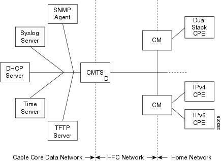
In this model, the different devices support the following functions and services:
Note | Cisco cBR routers support CPE devices provisioned for dual stack operation. |
- Cable modem (CM)—Functions as a bridging device and supports IPv4, IPv6, or dual stack operation.
- Cable modem termination system (CMTS) router—Works with the CM over the hybrid fiber coaxial cable (HFC) network to provide IPv4 and/or IPv6 network connectivity to the provisioning servers and the core data network behind the CMTS router.
The CMTS router supports IPv6 address assignment, routing, and forwarding of IPv6 multicast and unicast packets.
Note | The Cisco cBR router supports only a single DHCPv6 IPv6 address per client cable modem or CPE. This restriction also applies to DHCPv6 Prefix Delegation prefixes. The reason for blocking more than one DHCPv6 address or prefix for a client is because the end-to-end network requires Source Address Selection (SAS) and all nodes in the end-to-end network may not support the correct SAS. Moreover, the SAS specification (RFC 3484) is being revised by the IETF to define the correct SAS behavior. |
- Simple Network Management Protocol (SNMP) agent—Provides management tools to configure and query devices on the network.
- Syslog server—Collects messages from the CM to support its functions.
- Dynamic Host Control Protocol (DHCP) server—The DOCSIS 3.0 network model supports both DHCPv4 and DHCPv6 servers to control the assignment of IP addresses.
- Time server—Provides the current time to the CM.
- Trivial File Transport Protocol (TFTP) server—Provides the CM configuration file.
Note | The Cisco CMTS router supports multiple IPv6 addresses per client CPE via DHCP. The Multiple IAPDs in a Single Advertise feature supports assignment of multiple IA_NA and IAPD to a client CPE. This feature removes the restriction introduced in Cisco IOS Release 12.2(33)SCA to enable allocation of multiple globally-reachable IPv6 addresses to home devices of the cable modem subscriber. |
Overview of Cable Modem IPv6 Address Provisioning
Prior to cable modem registration with a CMTS router, the CMTS router sends a MAC Domain Descriptor (MDD) message to provide information to the cable modem about its supported IP provisioning mode. You configure the CMTS router provisioning mode using the cable ip-init interface configuration command. For more information, see the Implementing IPv6 Addressing and Basic Connectivity for Cable Interfaces and Bundles.
The MDD contains an IP initialization parameters type length value (TLV) that defines the IP version, management and alternate provisioning mode, and pre-registration downstream service ID (DSID) that is used by cable modems that are capable of downstream traffic filtering.
Note | The Cisco CMTS routers do not support alternate provisioning mode or pre-registration DSID. |
To support the MULPIv3.0 I04 or later version of the DOCSIS 3.0 MAC and Upper Layer Protocols Interface Specification, the cable modem must attempt IPv6 address acquisition first.
Figure below illustrates the message flow between a cable modem, the CMTS router, and the DHCP server when the cable modem is requesting an IPv6 address.
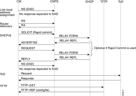
- Link-local address assignment—The cable modem sends a Neighbor Solicit (NS) message with its link-local address (LLA) to the CMTS router, which starts the duplicate address detection (DAD) process for that LLA. The cable modem expects no response to the NS message.
- Router discovery—The cable modem listens to the downstream to detect periodical Router Advertise (RA) messages. When an RA message is detected, the cable modem uses the data in the RA message to configure the default route. If an RA is not detected in a specified period, the cable modem sends a Router Solicit (RS) message to find the router on the link (all nodes multicast). The CMTS router responds with a Router Advertise (RA) message with theM and O bits set to 1 to instruct the CM to perform stateful address configuration.
Note | Cisco CMTS routers do not support SLAAC address assignment. |
- DHCPv6—The cable modem sends a DHCPv6 Solicit message to the CMTS router to request an IPv6 address. The CMTS router relays this message to the DHCPv6 servers. The DHCPv6 servers send an Advertise message indicating the server’s availability.
If the Rapid-Commit option is not used by the cable modem, then the cable modem responds to the Advertise message of the server with a Request message to select the server that the CMTS router relays to the DHCPv6 server. If the Rapid-Commit option is used, then multiple DHCPv6 servers that could assign different addresses to the same CPE must not be used.
The cable modem starts the DAD process to verify the uniqueness of the IPv6 address that the DHCPv6 server assigns to it.
Overview of IPv6 Dual Stack CPE Support on the CMTS
Most operating systems (OS) deployed at homes support dual stack operation. Cisco CMTS supports dual stack, which is both IPv4 and IPv6 addressing on the CPE.
Overview of IPv6 over Subinterfaces
Cisco CMTS supports IPv6 over bundle subinterfaces. To configure IPv6 on bundle subinterfaces, see the Implementing IPv6 Addressing and Basic Connectivity for Cable Interfaces and Bundles section. For a CMTS bundle configuration example, see the Example: IPv6 over Subinterfaces section.
To enable IPv6 on subinterfaces, configure IPv6 on bundle subinterfaces and not the bundle. Reset the CMs after the subinterface is configured.
Note | MPLS VPN over subinterfaces for IPv6 is not supported. |
Overview of High Availability on IPv6
Cisco cBR Series routers support IPv6 HA for the Supervisor card.
Note | IPv6 DOCSIS HA and HCCP is supported on the Cisco CMTS routers. |
The IPv6 HA feature support in Cisco CMTS routers covers the following capabilities:
DOCSIS PRE HA
The DOCSIS PRE HA has the following behavior restrictions and prerequisites on the Cisco CMTS routers:
- The CMs and CPEs should not go offline after a PRE switchover.
- The data structures of the IPv6 CM and CPE should be synchronized to the standby PRE before the PRE switchover. Both dynamic and bulk synchronization is supported.
- Single stack, dual stack, and APM are supported for the CM.
- Single stack and dual stack provisioning modes are supported on the CPE.
- After a PRE switchover, the IPv6 neighbor entries are rebuilt by Neighbor Discovery (ND) messages on the standby PRE, and the IPv6 routes are rebuilt after converging the routing protocol.
DOCSIS Line Card HA
The DOCSIS line card HA has the following behavior restrictions and prerequisites on the Cisco CMTS routers:
- The data structures of the IPv6 CM and CPE should be synchronized to the standby line card before the line card switchover. Both dynamic and bulk synchronization is supported.
- The CMs and CPEs should not fall offline after a line card switches over and reverts; the CMs and CPEs should behave the same as before the switchover.
- The DOCSIS line card HA supports both 4+1 and 7+1 redundancy.
- Traffic outages in IPv6 may be longer because traffic recovery occurs only after converging the routing protocol.
Dynamic Channel Change
The Dynamic Channel Change (DCC) feature is supported on Cisco CMTS routers.
Note | The behavior of the DCC for single stack IPv6 CM and CPE, or dual stack CM and CPE is the same as that of a single stack IPv4 CM and CPE. |
The IPv6 and IPv4 DCC functionality has the following behavior restrictions and prerequisites on the Cisco CMTS routers:
Narrowband Cable Modem
- If the source and destination MAC domains of the CM are on the same line card, DCC initialization techniques 0, 1, 2, 3, and 4 are used to move the CM and its associated CPE from one upstream or downstream to another; or move the CM and CPE from one upstream and downstream combination to another.
- If the source and destination MAC domains of the CM are on different line cards, you can use only the DCC initialization technique 0 to move the CM and its associated CPE across line cards.
Wideband Cable Modem
- If the source and destination MAC domains of the CM are on the same line card, DCC initialization techniques 0, 1, 2, 3, and 4 are used to move the CM and its associated CPE from one upstream to another.
- If the primary downstream of a CM is changed after DCC, you can use only the DCC initialization technique 0 to move the CM and its associated CPE across line cards.
Overview of IPv6 VPN over MPLS
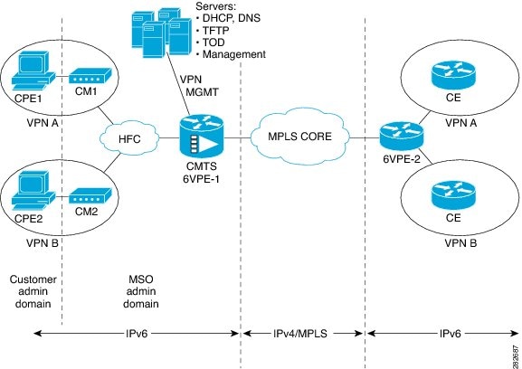
The Multiprotocol Label Switching (MPLS) VPN feature represents an implementation of the provider edge (PE) based VPN model. This document describes the IPv6 VPN over MPLS (6VPE) feature.
The 6VPE feature allows Service Providers to provide an IPv6 VPN service that does not require an upgrade or reconfiguration of the PE routers in the IPv4 MPLS Core. The resulting IPv6 VPN service has a configuration and operation which is virtually identical to the current IPv4 VPN service.
In principle, there is no difference between IPv4 and IPv6 VPNs. In both IPv4 and IPv6, the multiprotocol BGP is the core of the MPLS VPN for IPv6 (VPNv6) architecture. It is used to distribute IPv6 routes over the service provider backbone using the same procedures to work with overlapping addresses, redistribution policies, and scalability issues.
Figure below illustrates the 6PE/6VPE reference architecture diagram.
For more information about these tasks, see the Implementing IPv6 VPN over MPLS chapter in the Cisco IOS IPv6 Configuration Guide, Release 12.2SR.
Cable Monitor
The Cable Monitor and Intercept features for Cisco CMTS routers provide a software solution for monitoring and intercepting traffic coming from a cable network. These features give service providers Lawful Intercept capabilities.
For more information, see Cable Monitor and Intercept Features for the Cisco CMTS Routers guide at: http://www.cisco.com/en/US/docs/ios/cable/configuration/guide/cmts_mon_intrcpt.html
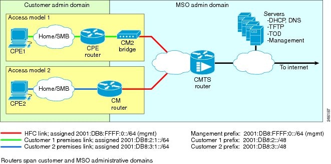
Overview of IPv6 CPE Router Support on the Cisco CMTS
The IPv6 CPE router support is provided on the Cisco CMTS. The IPv6 CPE router is a node primarily for home or small office use that connects the end-user network to a service provider network. It is also referred to as the home router.
The IPv6 CPE router is responsible for implementing IPv6 routing; that is, the IPv6 CPE router looks up the IPv6 destination address in its routing table and decides to which interface the packet should be sent.
The IPv6 CPE router performs the following functions:
- Provisions its WAN interface automatically.
- Acquires IP address space for provisioning of its LAN interfaces.
- Fetches other configuration information from the service provider network.
Figure below illustrates the CPE router reference architecture diagram between the CPE router, the CMTS, and the DHCPv6 server (CNR) when the CM is requesting an IPv6 address.
As part of the IPv6 CPE Router Support feature, the following enhancements are introduced:
Support for IPv6 Prefix Stability on the CMTS
IPv6 prefix stability is supported on the Cisco CMTS as specified in DOCSIS 3.0 MULPI CM-SP-MULPIv3.0-I15-110210 standard. The IPv6 prefix stability allows an IPv6 home router to move from one Cisco CMTS to another while retaining the same prefix.
The multiple service operators (MSOs) can use this feature to allow their business customers (with IPv6 routers) to retain the same IPv6 prefix during a node split.
Configurable DHCPv6 Relay Address
The DHCPv6 Cisco IOS relay agent on the Cisco CMTS router sends relay-forward messages from a source address to all configured relay destinations. The source address is either an IPv6 address provisioned on the network interface or a Cisco CMTS WAN IPv6 address. The relay destination can be a unicast address of a server, another relay agent, or a multicast address. The relay-forward messages contain specific DHCPv6 link-addresses.
A DHCP relay agent is used to relay messages between the client and server. A client locates a DHCP server using a reserved, link-scoped multicast address.
DHCPv6 Client Link-Layer Address Option (RFC 6939)
Cisco IOS Release 12.2(33)SCI1 supports DHCPv6 Client Link-Layer Address Option (RFC 6939). It defines an optional mechanism and the related DHCPv6 option to allow first-hop DHCPv6 relay agents (relay agents that are connected to the same link as the client) to provide the client's link-layer address in the DHCPv6 messages being sent towards the server.
The format of the DHCPv6 Client Link-Layer Address option is shown below.
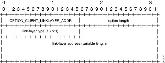
|
Name |
Description |
|---|---|
|
option-code |
OPTION_CLIENT_LINKLAYER_ADDR (79) |
|
option-length |
2 + length of MAC address |
|
link-layer type |
CPE or CM MAC address type. The link-layer type MUST be a valid hardware type assigned by the IANA, as described in RFC0826. |
|
link-layer address |
MAC address of the CPE or CM. |
Note | Starting with Cisco IOS Release 12.2(33)SCI1, RFC6939 is enabled by default. It can not be enabled/disabled by any CLI command. |
To configure DHCPv6 Relay Address on the Cisco CMTS bundle subinterfaces, see the Configuring DHCPv6 Relay Agent section.
For more information about the DHCPv6 client, server, and relay functions, see the “Implementing DHCP for IPv6” chapter in the Cisco IOS IPv6 Configuration Guide, Release 12.2SR .
Support for Multiple IAPDs in a Single Advertise
Assignment of multiple IA_NA and IAPD to CPEs behind a CM is supported on Cisco CMTS routers. This feature includes support for link-local addresses and IA_NA and IAPD. However, a CM can be assigned only one IA_NA. This IA_NA can be either static or DHCP-assigned.
The CPEs behind the CM can request for multiple DHCPv6 IA_NAs and IAPDs. Each CPE is assigned multiple IA_NAs and IAPDs in a single Advertise/Reply message. Each CPE request for IA_NA and IAPD is treated as a separate Advertise/Reply message.
IPv6 Neighbor Discovery Gleaning
The IPv6 Neighbor Discovery (ND) Gleaning feature enables Cisco CMTS routers to automatically recover lost IPv6 CPE addresses and update the CPE records in the Cisco CMTS subscriber database. The Cisco CMTS router gleans only the solicited neighbor advertise (NA) messages transmitted in the upstream direction. IPv6 ND gleaning is similar to Address Resolution Protocol (ARP) gleaning for IPv4 CPE recovery.
The IPv6 ND Gleaning feature is configured by default on Cisco CMTS routers. To disable this feature, use the no form of the cable nd command in bundle interface configuration mode. The cable nd command adds a CPE (host behind a cable modem) to the Cisco CMTS subscriber database. This command does not impact the IPv6 ND protocol operation on the router.
Note | The IPv6 ND Gleaning feature does not support gleaning of NA messages transmitted in the downstream direction. |
How to Configure IPv6 on Cable
This section includes the following tasks:
- Configuring IPv6 Switching Services
- Implementing IPv6 Addressing and Basic Connectivity for Cable Interfaces and Bundles
- Configuring IPv6 Cable Filter Groups
- Configuring IPv6 Cable Filter Groups
- Configuring IPv6 Domain Name Service
- Configuring IPv6 Source Verification
- Configuring IPv6 VPN over MPLS
- Configuring DHCPv6 Relay Agent
- Disabling IPv6 ND Gleaning
Configuring IPv6 Switching Services
The CMTS routers support forwarding of unicast and multicast IPv6 traffic using either Cisco Express Forwarding for IPv6 (CEFv6) or distributed CEFv6 (dCEFv6):
The CMTS routers also support Unicast Reverse Path Forwarding (RPF), as long as you enable Cisco Express Forwarding switching or distributed Cisco Express Forwarding switching globally on the router. There is no need to configure the input interface for Cisco Express Forwarding switching. As long as Cisco Express Forwarding is running on the router, individual interfaces can be configured with other switching modes.
To configure forwarding of IPv6 traffic using Cisco Express Forwarding or distributed Cisco Express Forwarding (supported on the Cisco uBR10012 universal broadband router only) on the CMTS routers, you must configure forwarding of IPv6 unicast datagrams using the ipv6 unicast-routing global configuration command, and you must configure an IPv6 address on the bundle interface using the ipv6 address command.
The show ipv6 cef platform command is supported on the Cisco CMTS platform from Cisco IOS Release 12.2(33)SCE onwards. You can use the show ipv6 cef platform command for debugging purposes.
-
You must enable Cisco Express Forwarding for IPv4 globally on the router by using the ip cef or ip cef distributed command before configuring Cisco Express Forwarding v6 or distributed Cisco Express Forwarding v6.
Note | The ip cef command is enabled by default on all Cisco CMTS routers. Therefore, you only must configure the command if it has been disabled. However, you must explicitly configure the ip cef distributed command on a Cisco uBR10012 universal broadband router if you want to run distributed CEF switching services for IPv4 or IPv6. |
Implementing IPv6 Addressing and Basic Connectivity for Cable Interfaces and Bundles
- Configuring the Cable Virtual Bundle Interface
- Configuring the IP Provisioning Mode and Bundle on the Cable Interface
Configuring the Cable Virtual Bundle Interface
The only required IPv6 configuration on a cable line card interface is the IP provisioning mode. The remainder of the IPv6 features are configured at the virtual bundle interface, which is then associated with a particular cable line card interface to establish its configuration.
Most of the IPv6 features that are supported in interface configuration mode (both cable-specific as well as platform-independent IPv6 features) are configured at a cable bundle interface.
The Cisco CMTS routers support IPv6 routing on the bundle interface and map both IPv6 unicast and multicast addresses into the cable bundle forwarding table, for packet forwarding.
Each bundle interface has a unique link-local address (LLA) to support link-local traffic when IPv6 is enabled. Cisco CMTS routers can support a maximum of 40 active bundle interfaces, which also translates to a maximum of 40 active IPv6-enabled bundle interfaces.
IPv6 commands can be configured on multiple bundle subinterfaces.
The cable ipv6 source-verify and cable nd commands are not compatible with each other in Cisco IOS release 12.2(33)SCE and later. You must disable IPv6 ND gleaning using the no form of the cable nd command before using the cable ipv6 source-verify command to ensure that only DHCPv6 and SAV-based CPEs can send traffic on the router.
All multicast traffic is flooded onto bundle member interfaces.
| Command or Action | Purpose | |
|---|---|---|
| Step 1 | enable
Example: Router> enable |
Enables privileged EXEC mode. Enter your password if prompted. |
| Step 2 | configure
terminal
Example: Router# configure terminal |
Enters global configuration mode. |
| Step 3 | interface
bundle
n
Example: Router(config)# interface bundle 1 |
Specifies the cable bundle interface and enters interface configuration mode, where n specifies the number of the bundle interface. |
| Step 4 | ipv6
addressipv6-prefix/prefix-length [eui-64 ]
Example: Router(config-if)# ipv6 address 2001:DB8::/32 eui-64 |
Specifies an IPv6 network assigned to the interface and enables IPv6 processing on the interface. The ipv6 address eui-64 command configures site-local and global IPv6 addresses with an interface identifier (ID) in the low-order 64 bits of the IPv6 address. You need to specify only the 64-bit network prefix for the address; the last 64 bits are automatically computed from the interface ID. |
| Step 5 |
ipv6
addressipv6-prefix
/prefix-length
link-local
Example: Router(config-if)# ipv6 address 2001:DB8::/32 link-local |
(Optional) Specifies an IPv6 address assigned to the interface and enables IPv6 processing on the interface. The ipv6 address link-local command configures a link-local address on the interface that is used instead of the link-local address that is automatically configured, when IPv6 is enabled on the interface (using the ipv6 enable command). |
| Step 6 | ipv6
enable
Example: Router(config-if)# ipv6 enable |
Automatically configures an IPv6 link-local address on the interface while also enabling the interface for IPv6 processing. The link-local address can be used only to communicate with nodes on the same link. |
| Step 7 | cable ipv6
source-verify
Example: Router(config-if)# cable ipv6 source-verify |
(Optional) Enables source verification of MAC address-MD-SID-IPv6 address binding packets received by a cable interface upstream on Cisco CMTS routers. |
Configuring the IP Provisioning Mode and Bundle on the Cable Interface
The CMTS routers allow you to configure cable interfaces to support cable modems provisioned for both IPv4 and IPv6 addressing support (known as “dual stack”), only IPv4 addressing, or only IPv6 addressing. Prior to cable modem registration, the CMTS router sends its supported provisioning mode to the cable modem in the MDD message.
In addition to configuring the provisioning mode on the cable interface, you must also associate the cable interface with a cable bundle. You perform most of the other IPv6 feature configuration at the bundle interface.
Note | This section describes only the commands associated with establishing IPv6 support on a CMTS router. Other cable interface commands that apply but are optional are not shown, such as to configure upstream and downstream features. |
Configuration of a bundle interface is required.
| Command or Action | Purpose | |
|---|---|---|
| Step 1 | enable
Example: Router> enable |
Enables privileged EXEC mode. Enter your password if prompted. |
| Step 2 | configure
terminal
Example: Router# configure terminal |
Enters global configuration mode. |
| Step 3 | interface
cable
{slot
/
port
|
slot
/
subslot
/port
}
Example: Router(config)# interface cable 5/0/1 |
Specifies the cable interface line card, where: The valid values for these arguments are dependent on your CMTS router and cable interface line card. Refer to the hardware documentation for your router chassis and cable interface line card for supported slot and port numbering. |
| Step 4 | cable
ip-init {apm |
dual-stack |
ipv4
|
ipv6}
Example: Router(config-if)# cable ip-init ipv6 |
Specifies the IP provisioning mode supported by the cable interface, where: |
| Step 5 | cable
bundlen
Example: Router(config)# cable bundle 1 |
Associates the cable interface with a configured virtual bundle interface, where n specifies the number of the bundle interface. |
- Proceed to configuring any other cable interface features that you want to support, such as upstream and downstream features. For more information about the other cable interface features, refer to the Cisco IOS CMTS Cable Software Configuration Guide .
- Proceed to configure other optional IPv6 cable features.
Configuring IPv6 Cable Filter Groups
The Cisco CMTS router supports IPv6 cable filter group capability with IPv6 filter options.
Configuring IPv6 Cable Filter Groups
The Cisco CMTS router supports IPv6 cable filter group capability with IPv6 filter options.
Cable Filter Groups and the DOCSIS Subscriber Management MIB
Cable subscriber management is a DOCSIS 1.1 specification, which can be established using the following configuration methods:
- CMTS router configuration (via CLI)
- SNMP configuration
- DOCSIS 1.1 configuration file (TLVs 35, 36, and 37)
This section describes the IPv6 cable filter group feature support of the packet filtering portion of the DOCSIS Subscriber Management MIB (DOCS-SUBMGMT-MIB) using configuration commands on the CMTS routers. This IPv6 cable filter group support extends filter classifiers with IPv6 addressing options for CM and CPE traffic, but is independent of DOCSIS IPv6 classifiers, which are used to match packets to service flows.
Configuration of IPv6 cable filter groups on the CMTS routers is supported according to the following guidelines:
- A cable filter group consists of a set of cable filter group commands that share the same group ID.
- Separate indexes can be used to define different sets of filters for the same group ID. This can be used to define both IPv4 and IPv6 filters to the same filter group.
- CMs can be
associated with one upstream and one downstream filter group.
- Upstream traffic—All traffic coming from CMs is evaluated against the assigned upstream filter group that is configured by the cable submgmt default filter-group cm upstream command.
- Downstream traffic—All traffic going to CMs is evaluated against the assigned downstream filter group that is configured by the cable submgmt default filter-group cm downstream command.
- CPEs can be
associated with one upstream and one downstream filter group.
- Upstream traffic—All traffic coming from CPEs is evaluated against the assigned upstream filter group that is configured by the cable submgmt default filter-group cpe upstream command.
- Downstream traffic—All traffic going to CPEs is evaluated against the assigned downstream filter group that is configured by the cable submgmt default filter-group cpe downstream command.
Note | Because TLVs 35, 36, and 37 do not apply to DOCSIS 1.0 CM configuration files, the only way to enable cable subscriber management for a DOCSIS 1.0 CM is to configure it explicitly on the Cisco CMTS router and activate it by using the cable submgmt default active global configuration command. |
You must create the cable filter group before you assign it to a CM or CPE upstream or downstream.
- Chained IPv6 headers are not supported.
- An individual filter group index cannot be configured to support both IPv4 and IPv6 versions at the same time. If you need to support IPv4 and IPv6 filters for the same filter group, then you must use a separate index number with the same filter group ID, and configure one index as ip-version ipv4, and the other index as ip-version ipv6.
- Only a single upstream and a single downstream filter group can be assigned for CM traffic.
- Only a single upstream and a single downstream filter group can be assigned to CPEs attached to a CM such that all CPEs behind a CM share a common filter group.
- For the filter group to work for CMs, a CM must re-register after the CMTS router is configured for the filter group.
- If parallel eXpress forwarding (PXF) is configured on the Cisco uBR10012 router, either the cable filter group commands or the interface ACL (ip access-list) command can be configured.
- If you do not provision TLVs 35, 36, and 37 in the DOCSIS CM configuration file, then you must activate the functionality by specifying the cable submgmt default active global configuration command on the CMTS router.
| Command or Action | Purpose | |||
|---|---|---|---|---|
| Step 1 | enable
Example: Router> enable |
Enables privileged EXEC mode. Enter your password if prompted. | ||
| Step 2 | configure
terminal
Example: Router# configure terminal |
Enters global configuration mode. | ||
| Step 3 | cable
filter
groupgroup-id
indexindex-numdest-portport-num
Example: Router(config)# cable filter group 1 index 1 dest-port 69 |
(Optional) Specifies the TCP/UDP destination port number that should be matched. The valid range is from 0 to 65535. The default value matches all TCP/UDP port numbers (IPv4 and IPv6 filters). | ||
| Step 4 | cable
filter
group
group-id
index
index-num
ip-proto
proto-type
Example: Router(config)# cable filter group 1 index 1 ip-proto 17 |
(Optional) Specifies the IP protocol type number that should be matched. The valid range is from 0 to 256, with a default value of 256 that matches all protocols (IPv4 and IPv6 filters). Some commonly used values are: | ||
| Step 5 | cable
filter
group
group-id
index
index-num
ip-tos
tos-mask
tos-value
Example: Router(config)# cable filter group 1 index 1 ip-tos 0xff 0x80 |
(Optional) Specifies a ToS mask and value to be matched (IPv4 and IPv6 filters): The tos-mask is logically ANDed with the tos-value and compared to the result of ANDing the tos-mask with the actual ToS value of the packet. The filter considers it a match if the two values are the same. The default values for both parameters matches all ToS values. | ||
| Step 6 | cable
filter
group
group-id
index
index-num
ip-version
ipv6
Example: Router(config)# cable filter group 1 index 1 ip-version ipv6 |
Specifies that this filter group is an IPv6 filter group. | ||
| Step 7 | cable
filter
group
group-id
index
index-num
match-action {accept
|
drop}
Example: Router(config)# cable filter group 1 index 1 match-action drop |
(Optional) Specifies the action that should be taken for packets that match this filter (IPv4 and IPv6 filters): | ||
| Step 8 | cable
filter
group
group-id
index
index-num
src-port
port-num
Example: Router(config)# cable filter group 1 index 1 src-port 50 |
(Optional) Specifies the TCP/UDP source port number that should be matched. The valid range is from 0 to 65535. The default value matches all TCP/UDP port numbers (IPv4 and IPv6 filters). | ||
| Step 9 | cable
filter
group
group-id
index
index-num
status
{active
|
inactive}
Example: Router(config)# cable filter group 1 index 1 status inactive |
(Optional) Enables or disables the filter (IPv4 and IPv6 filters):
| ||
| Step 10 | cable
filter
group
group-id
index
index-num
tcp-flags
flags-mask
flags-value
Example: Router(config)# cable filter group 1 index 1 tcp-flags 0 0 |
(Optional) Specifies the TCP flag mask and value to be matched (IPv4 and IPv6 filters): | ||
| Step 11 | cable
filter
group
group-id
index
index-num
v6-dest-address
ipv6-address
Example: Router(config)# cable filter group 1 index 1 v6-dest-address 2001:DB8::/32 |
(Optional) Specifies the IPv6 destination address that should be matched using the format X:X:X:X::X (IPv6 filters only). | ||
| Step 12 | cable
filter
group
group-id
index
index-num
v6-dest-pfxlen
prefix-length
Example: Router(config)# cable filter group 1 index 1 v6-dest-pfxlen 64 |
(Optional) Specifies the length of the network portion of the IPv6 destination address. The valid range is from 0 to 128. | ||
| Step 13 | cable
filter
group
group-id
index
index-num
v6-src-address
ipv6-address
Example: Router(config)# cable filter group 1 index 1 v6-src-address 2001:DB8::/32 |
(Optional) Specifies the IPv6 source address that should be matched using the format X:X:X:X::X (IPv6 filters only). | ||
| Step 14 | cable
filter
group
group-id
index
index-num
v6-src-pfxlen
prefix-length
Example: Router(config)# cable filter group 1 index 1 v6-src-pfxlen 48 |
(Optional) Specifies the length of the network portion of the IPv6 source address. The valid range is from 0 to 128 (IPv6 filters only). | ||
| Step 15 | cable
submgmt
default
filter-group {cm
|
cpe}
{downstream
|
upstream}
group-id
Example: Router(config)# cable submgmt default filter-group cm upstream 1 |
Applies a defined filter group (by specifying its group-id) to either a CM or its CPE devices, for downstream or upstream traffic. | ||
| Step 16 | cable
submgmt
default
active
Example: Router(config)# cable submgmt default active |
(Required if you do not provision TLVs 35, 36, and 37 in the DOCSIS 1.1 CM configuration file) Enables filters and allows the CMTS to manage the CPE devices for a particular CM (sets the docsSubMgtCpeActiveDefault attribute to TRUE). |
The following example shows how to create an IPv6 filter group with ID 254 and an index number of 128. The ip-version ipv6 keywords must be configured to create the IPv6 filter group; otherwise, the default is an IPv4 filter group:
configure terminal
cable filter group 254
 index 128 v6-src-address 2001:DB8::/32
cable filter group 254
 index 128 v6-src-pfxlen 48
cable filter group 254
 index 128 v6-dest-address 2001:DB8::/32
cable filter group 254
 index 128 v6-dest-pfxlen 64
cable filter group 254
 index 128 ip-version ipv6
cable filter group 254
 index 128 match-action drop
cable submgmt default filter-group cm upstream 254
This group filters CM upstream traffic and drops any packets with an IPv6 source address of 2001:33::20B:BFFF:FEA9:741F (with network prefix of 128) destined for an IPv6 address of 2001:DB8::/32 (with network prefix of 128).
All of the cable filter group commands are associated by their group ID of 254 (and index of 128), and the cable submgmt default filter-group command applies the corresponding filter group ID of 254 to CM upstream traffic.
To monitor your cable filter group configuration, use forms of the show cable filter command as shown in the following examples. In these output examples, the output from the show cable filter, show cable filter group 254, and show cable filter group 254 index 128 commands all display the same information because there is currently only a single filter group and index defined.
Note | The “Use Verbose” string appears in the output area of the SrcAddr/mask and DestAddr/Mask fields suggesting use of the show cable filter group verbose form of the command to display the complete IPv6 address. |
Router# show cable filter
Filter    SrcAddr/Mask       DestAddr/Mask      Prot ToS  SPort DPort TCP   Action Status
Grp Id v6                                                             Flags
254 128Y  Use Verbose
        Use Verbose
                                    drop   active
Router# show cable filter group 254
Filter    SrcAddr/Mask       DestAddr/Mask      Prot ToS  SPort DPort TCP   Action Status
Grp Id v6                                                             Flags
254 128Y  Use Verbose        Use Verbose                                    drop   active
Router# show cable filter group 254 index 128
Filter    SrcAddr/Mask       DestAddr/Mask      Prot ToS  SPort DPort TCP   Action Status
Grp Id v6                                                             Flags
254 128Y  Use Verbose        Use Verbose                                    drop   active
Router# show cable filter group 254 index 128 verbose
Filter Group                         : 254
Filter Index                         : 128
Filter Version                       : IPv6
Matches                              : 0
    Source IPv6 address              : 2001:DB8::/32
    Destination IPv6 address         : 2001:DB8::/32
    Match action                     : drop
    Status                           : active
Troubleshooting Tips
You should configure the cable filter group commands prior to applying a filter group using the cable submgmt default filter-group command. Failure to do so results in the following message, and an association to a filter group that is undefined:
Router(config)# cable submgmt default filter-group cm upstream 100
Default value set to a nonexistent filter-group 100.
Configuring IPv6 Domain Name Service
Cisco IOS Release 12.2(33)SCA introduces the domain name service (DNS) capability for devices using IPv6 addressing on the Cisco CMTS routers.
DNS simplifies the identification of cable devices by associating a hostname with what can often be a complex 128-bit IPv6 address. The hostname can then be used in place of the IPv6 address within the CMTS router CLI that supports use of hostnames.
There are two separate DNS caches supported on a CMTS router—an IOS DNS cache and a cable-specific DNS cache that stores IPv6 addresses learned by the CMTS router for CMs and CPEs.
In this phase of the IPv6 DNS service on cable, the DNS server is queried for domain name information as needed when you use the show cable modem domain-name command. When you use this command, the following actions take place:
- The CMTS router checks whether CMs are online. If a CM is online, the CMTS router uses the corresponding IPv6 address assigned to the CM and looks up its domain name from the IOS DNS cache.
- If no match is found, the CMTS router sends a DNS-QUERY message with the IPv6 address of the CM to the DNS server, which tries to resolve the domain name.
- When the DNS reply is received, the CMTS router stores the domain name in the IOS DNS cache for each IPv6 address.
- The CMTS router also stores the fully-qualified domain name (FQDN) that is replied by the DNS server in the cable-specific DNS cache.
Note | Running the no ip domain lookup command will turn off the DNS resolution. |
The following platform-independent Cisco IOS software commands are supported using host names by the CMTS router for IPv6 DNS on cable:
- connect
- ping ipv6
- show hosts
- telnet
- traceroute
- A DNS server must be configured.
- You must identify and assign the host names to the IPv6 addresses. If you are using the Cisco DNS server, use the ip host global configuration command to map hostnames to IP addresses.
- You must configure the DNS server using the ip name-server global configuration command before use of DNS host names (or domains) are available in the supported commands.
- The show cable modem domain-name command must be run first on the Route Processor (RP) of the CMTS router before any domain name can be used as part of a cable command.
For more information about configuring these prerequisites and related IP domain configuration options, refer to the Mapping Host Names to IP Addresses section in the Cisco IOS IP Configuration Guide at:
- DNS for cable devices using IPv4 addressing is not supported.
- Due to column size limitations within the command-line interface (CLI), the domain name display is limited to 32 characters. Therefore, the entire domain name cannot always be seen in CMTS router command output.
- Only those cable devices where IPv6 address learning takes place are supported, such as acquiring an IPv6 address through DHCPv6 or the IPv6 (ND) process.
- The cable-specific DNS cache is only updated when you use the show cable modem domain-name command on the Route Processor (RP). A DNS-QUERY can only be sent on the RP using this command, therefore the DNS cache cannot update if you use the show cable modem domain-name command on a line card console. The output is displayed on the RP only.
- The cable-specific DNS cache does not store partially qualified domain names, only FQDNs are stored.
- The cable-specific DNS cache is not associated with the timeouts that apply to the IOS DNS cache. Therefore, a cable-specific DNS cache entry is not removed when an IOS DNS cache timeout occurs for that device. The cable-specific DNS cache is only updated when you use the show cable modem domain-name command.
- The CMTS router supports storage of only one domain name per IPv6 address in the cable-specific DNS cache.
- Domain names for the link local address are not supported.
- The no ip domain-name command disables DNS lookup.
| Command or Action | Purpose | |
|---|---|---|
| Step 1 | enable
Example: Router> enable |
Enables privileged EXEC mode. Enter your password if prompted. |
| Step 2 | configure
terminal
Example: Router# configure terminal |
Enters global configuration mode. |
| Step 3 | ip
name-server [vrf
vrf-name]
server-address1 [server-address2...server-address6]
Example: Router(config)# ip name-server 2001:DB8::/32 |
Specifies the address of one or more name servers to use for name and address resolution. |
| Step 4 | exit
Example: Router(config)# exit |
Leaves global configuration mode and enters privileged EXEC mode. |
| Step 5 | show
cable
modem
domain-name
Example: Router# show cable modem domain-name |
Updates the cable-specific DNS cache and displays the domain name for all CMs and the CPE devices behind a CM. |
Configuring IPv6 Source Verification
Typically, the IPv6 source verification feature is enabled on a cable bundle interface. From there, the cable interface is associated with the virtual bundle interface to acquire its configuration.
When you enable IPv6 source verification on a cable line card interface, the source verification routine verifies the MAC address-MD-SID-IP binding of the packet. If the source verification succeeds, the packet is forwarded. If the verification fails, the packet is dropped.
When a CM is operating as a bridge modem device, then the CMTS router verifies all the IPv6 addresses related to that CM and the CPEs behind that CM.
The cable ipv6 source-verify command controls only the source verification of IPv6 packets. For IPv4-based source verification, use the cable source-verify command, which also supports different options.
For more information about how to configure IPv6 source verification on a bundle interface, see the Configuring the Cable Virtual Bundle Interface.
Restrictions
Source verification of IPv6 packets occurs only on packets in the process-switched path of the Route Processor (RP).
Configuring IPv6 VPN over MPLS
The Cisco CMTS routers support the IPv6 VPN over MPLS (6VPE) feature. Implementing this feature includes the following configuration tasks.
- Configuring a VRF instance for IPv6
- Binding a VRF to an interface
- Creating a subinterface
- Configuring a static route for PE-to-CE-routing
- Configuring eBGP PE-to-CE routing sessions
- Configuring the IPv6 VPN address family for iBGP
- Configuring route reflectors for improved scalability
- Configuring Internet access
For detailed information about these tasks, see the Implementing IPv6 VPN over MPLS chapter in the Cisco IOS IPv6 Configuration Guide, Release 12.2SR at:
For detailed information about the configuration examples, see Configuration Examples for IPv6 on Cable.
Note | The IPv6 address of the sub-bundle interface (to which the CM is connected) is used in the DHCPv6 relay packet of the CPE DHCPv6 request. If the DHCPv6 packet has to go from one VRF interface to another, the IPv6 address of each VRF interface should be configured on the Cisco CMTS to establish connectivity. |
Configuring DHCPv6 Relay Agent
The Cisco CMTS router supports DHCPv6 relay agent to forward relay-forward messages from a specific source address to client relay destinations.
Perform the steps given below to enable the DHCPv6 relay agent function and specify relay destination addresses on an interface.
The relay-forward messages should contain specific source IPv6 address. This is required because the firewall deployed between the Cisco CMTS DHCPv6 relay agent and the DHCPv6 server expects only one source address for one Cisco CMTS bundle interface.
If you change one or more parameters of the ipv6 dhcp relay destination command, you have to disable the command using the no form, and execute the command again with changed parameters.
| Command or Action | Purpose | |
|---|---|---|
| Step 1 | enable
Example: Router> enable |
Enables privileged EXEC mode. Enter your password if prompted. |
| Step 2 | configure
terminal
Example: Router# configure terminal |
Enters global configuration mode. |
| Step 3 |
interface
type
number
Example: Router(config)# interface ethernet 4/2 |
Specifies an interface type and number, and places the router in interface configuration mode. |
| Step 4 |
ipv6
dhcp
relay
destination
ipv6-address[
interface] [link-address
link-address
] [
source-address
source-address]
Example: Router(config-if) ipv6 dhcp relay destination 2001:db8:1234::1 ethernet 4/2 link-address 2001:db8::1 source-address 2001:db8::2 |
Specifies a destination address to which client packets are forwarded and enables DHCPv6 relay service on the interface. |
| Step 5 |
end
Example: Router(config-if) end |
Exits interface configuration mode and enters privileged EXEC mode. |
Disabling IPv6 ND Gleaning
You must disable IPv6 ND gleaning before configuring IPv6 source verification using DHCPv6 leasequery.
| Command or Action | Purpose | |
|---|---|---|
| Step 1 | enable
Example: Router> enable |
Enables privileged EXEC mode. Enter your password if prompted. |
| Step 2 | configure
terminal
Example: Router# configure terminal |
Enters global configuration mode. |
| Step 3 |
interfacebundle bundle-no
Example: Router(config)# interface bundle 1 |
Specifies a bundle interface number and enters bundle interface configuration mode. |
| Step 4 |
no
cable
nd
Example: Router(config-if) no cable nd |
Disables IPv6 ND gleaning on the Cisco CMTS router. |
| Step 5 |
end
Example: Router(config-if) end |
Returns to privileged EXEC mode. |
How to Verify IPv6 Dual Stack CPE Support
This section describes how to use show commands to verify the configuration of the IPv6 Dual Stack CPE Support on the CMTS feature.
| Command or Action | Purpose | |
|---|---|---|
| Step 1 | enable
Example: Router> enable |
Enables privileged EXEC mode. Enter your password if prompted. |
| Step 2 | show
cable
modem
[ip-address |
mac-address ]
ipv6[
cpe
|
prefix |
registered
|
unregistered]
Example: Router# show cable modem ipv6 registered Example: Router# show cable modem 0019.474a.c14a ipv6 cpe |
Displays IPv6 information for specified CMs and CPEs behind a CM on a Cisco CMTS router. You can specify the following options: |
| Step 3 | show
cable
modem
[ip-address | mac-address]
registered
Example: Router# show cable modem 0019.474e.e4DF registered |
Displays a list of the CMs that have registered with the Cisco CMTS. You can specify the following options: |
| Step 4 | show
cable
modem {ip-address | mac-address}
cpe
Example: Router# show cable modem 0019.474a.c14a cpe |
Displays the CPE devices accessing the cable interface through a particular CM. You can specify the following options: |
Examples
Use the show cable modem ipv6 command to display the IPv6 portion of a dual stack CPE and use the show cable modem cpe command to display the IPv4 mode of a dual stack CPE. Both show cable modem ipv6 registered and show cable modem registered commands display CPE count as one for a dual stack CPE.
The following example shows the output of the show cable modem ipv6 command:
Router# show cable modem ipv6 registered
Interface   Prim Online       CPE IP Address                              MAC Address
            Sid  State
C4/0/U2     1    online       0   ---                                     0019.474a.c18c
C4/0/U2     3    online(pt)   1   2001:420:3800:809:EDA4:350C:2F75:4779   0019.474a.c14a
Router# show cable modem 0019.474a.c14a ipv6 cpe
MAC Address    IP Address                              Domain Name
0005.0052.2c1d 2001:420:3800:809:48F7:3C33:B774:9185
Starting from Cisco IOS Release 12.2(33)SCG1, the output of the show cable modem ipv6 command for keyword cpe is changed.
The following example shows the output of the show cable modem ipv6 command:
Router# show cable modem
 0023.bed9.4c8e ipv6 cpe
Load for five secs: 0%/0%; one minute: 1%; five minutes: 1%
Time source is hardware calendar, *06:37:20.439 UTC Thu Aug 2 2012
MAC Address    IP Address
0023.bed9.4c91 2001:40:3:4:200:5EB7:BB6:C759
               2001:40:3:4:210:D73B:7A50:2D05
The following example shows the output of the show cable modem registered command:
Router# show cable modem registered
Interface   Prim Online      Timing Rec   QoS CPE IP address      MAC address
            Sid  State       Offset Power
C4/0/U2     3    online      1022   0.00  2   1   50.3.37.12      0019.474a.c14a
The following example shows the output of the show cable modem cpe command:
Router# show cable modem 0019.474a.c14a cpe

IP address        MAC address      Dual IP
50.3.37.3 0005.0052.2c1d Y
Configuration Examples for IPv6 on Cable
This section includes the following examples:
- Example: IPv6 over Subinterfaces
- Example: Basic IPv6 Cable Filter Groups
- Example: Complete Cable Configuration with IPv6
- Example: BGP Configuration for 6VPE
- Example: Subinterface Configuration for 6VPE
- Example: Cable Interface Bundling
- Example: VRF Configuration for 6VPE
Example: IPv6 over Subinterfaces
The following example shows the CMTS bundle configuration that can be used with subinterfaces:
Router# show cable modem ipv6
Device Type: B - CM Bridge, R - CM Router
IP Assignment Method: D - DHCP
MAC Address    Type Interface    Mac State    D/IP IP Address
0019.474a.c18c B/D  C4/0/U2      online        Y  2001:420:3800:809:4C7A:D518:91
C6:8A18
Router# show run interface bundle2
Building configuration...
Current configuration : 138 bytes
!
interface Bundle2
 no ip address
 cable arp filter request-send 3 2
 cable arp filter reply-accept 3 2
 no cable ip-multicast-echo
end
Router#

show run interface bundle2.1
Building configuration...
Current configuration : 382 bytes
!
interface Bundle2.1
 ip address 50.3.37.1 255.255.255.0
 no cable ip-multicast-echo
 cable helper-address 10.10.0.12
 ipv6 address 2001:DB8::/32
 ipv6 enable
 ipv6 nd prefix default no-advertise
 ipv6 nd managed-config-flag
 ipv6 nd other-config-flag
 ipv6 nd ra interval msec 2000
 ipv6 dhcp relay destination 2001:420:3800:800:203:BAFF:FE11:B644
 arp timeout 240
end
Example: Basic IPv6 Cable Filter Groups
The following example shows the configuration of an IPv6 filter group that drops traffic from a specific IPv6 host (with source address 2001:DB8::1/48) behind a cable router to an IPv6 host on the network (with destination address 2001:DB8::5/64):
configure terminal
!
! Specify the filter group criteria using a common group ID
!
cable filter group 254 index 128 v6-src-address 2001:DB8::1
cable filter group 254 index 128 v6-src-pfxlen 128
cable filter group 254 index 128 v6-dest-address 2001:DB8::5
cable filter group 254 index 128 v6-dest-pfxlen 128
!
! Specify that the filter group is IP version 6
!
cable filter group 254 index 128 ip-version ipv6
!
! Specify the drop action for matching packets
!
cable filter group 254 index 128 match-action drop
!
! Apply the filter group with ID 254 to all CM upstream traffic
!
cable submgmt default filter-group cm upstream 254
Example: Complete Cable Configuration with IPv6
The following example shows a complete cable configuration example; it also displays the configuration of multiple cable filter groups using both IPv4 and IPv6 and separate indexes to associate the filter definitions with the same group ID.
Router# show running-config
Building configuration...
Current configuration : 15010 bytes
!
! Last configuration change at 08:32:14 PST Thu Nov 8 2007
!
version 12.2
no service pad
service timestamps debug uptime
service timestamps log uptime
no service password-encryption
service internal
service compress-config
!
hostname router
!
boot-start-marker
boot-end-marker
!
enable password password1
!
no aaa new-model
clock timezone PST -9
clock summer-time PDT recurring
clock calendar-valid
facility-alarm core-temperature major 53
facility-alarm core-temperature minor 45
facility-alarm core-temperature critical 85
facility-alarm intake-temperature major 49
facility-alarm intake-temperature minor 40
facility-alarm intake-temperature critical 67
!
!
card 1/0 2jacket-1
card 1/0/0 24rfchannel-spa-1
card 5/0 5cable-mc520h-d
cable admission-control preempt priority-voice
cable modem vendor 00.18.68 SA-DPC2203
cable modem vendor 00.19.47 SA-DPC2505
no cable qos permission create
no cable qos permission update
cable qos permission modems
!
cable filter group 1 index 1 src-ip 0.0.0.0
cable filter group 1 index 1 src-mask 0.0.0.0
cable filter group 1 index 1 dest-ip 0.0.0.0
cable filter group 1 index 1 dest-mask 0.0.0.0
cable filter group 2 index 1 src-ip 0.0.0.0
cable filter group 2 index 1 src-mask 0.0.0.0
cable filter group 2 index 1 dest-ip 0.0.0.0
cable filter group 2 index 1 dest-mask 0.0.0.0
cable filter group 3 index 1 src-ip 0.0.0.0
cable filter group 3 index 1 src-mask 0.0.0.0
cable filter group 3 index 1 dest-ip 0.0.0.0
cable filter group 3 index 1 dest-mask 0.0.0.0
cable filter group 4 index 1 src-ip 0.0.0.0
cable filter group 4 index 1 src-mask 0.0.0.0
cable filter group 4 index 1 dest-ip 0.0.0.0
cable filter group 4 index 1 dest-mask 0.0.0.0
cable filter group 5 index 1 src-ip 0.0.0.0
cable filter group 5 index 1 src-mask 0.0.0.0
cable filter group 5 index 1 dest-ip 0.0.0.0
cable filter group 5 index 1 dest-mask 0.0.0.0
cable filter group 6 index 1 src-ip 0.0.0.0
cable filter group 6 index 1 src-mask 0.0.0.0
cable filter group 6 index 1 dest-ip 0.0.0.0
cable filter group 6 index 1 dest-mask 0.0.0.0
cable filter group 7 index 1 src-ip 0.0.0.0
cable filter group 7 index 1 src-mask 0.0.0.0
cable filter group 7 index 1 dest-ip 0.0.0.0
cable filter group 7 index 1 dest-mask 0.0.0.0
cable filter group 8 index 1 src-ip 0.0.0.0
cable filter group 8 index 1 src-mask 0.0.0.0
cable filter group 8 index 1 dest-ip 0.0.0.0
cable filter group 8 index 1 dest-mask 0.0.0.0
cable filter group 9 index 1 src-ip 0.0.0.0
cable filter group 9 index 1 src-mask 0.0.0.0
cable filter group 9 index 1 dest-ip 0.0.0.0
cable filter group 9 index 1 dest-mask 0.0.0.0
cable filter group 10 index 1 src-ip 0.0.0.0
cable filter group 10 index 1 src-mask 0.0.0.0
cable filter group 10 index 1 dest-ip 0.0.0.0
cable filter group 10 index 1 dest-mask 0.0.0.0
cable filter group 12 index 1 src-ip 0.0.0.0
cable filter group 12 index 1 src-mask 0.0.0.0
cable filter group 12 index 1 dest-ip 0.0.0.0
cable filter group 12 index 1 dest-mask 0.0.0.0
cable filter group 16 index 1 src-ip 0.0.0.0
cable filter group 16 index 1 src-mask 0.0.0.0
cable filter group 16 index 1 dest-ip 0.0.0.0
cable filter group 16 index 1 dest-mask 0.0.0.0
ip subnet-zero
ip domain name cisco.com
ip host host1 239.192.254.254
ip host host2 239.192.254.253
ip name-server 10.39.26.7
ip name-server 2001:0DB8:4321:FFFF:0:800:20CA:D8BA
!
!
!
!
ipv6 unicast-routing
ipv6 cef
packetcable multimedia
packetcable
!
!
!
redundancy
 mode sso
!
!
controller Modular-Cable 1/0/0
 annex B modulation 64qam 0 23
 ip-address 10.30.4.175
 modular-host subslot 5/0
 rf-channel 0 cable downstream channel-id 24
 rf-channel 1 cable downstream channel-id 25
 rf-channel 2 cable downstream channel-id 26
 rf-channel 3 cable downstream channel-id 27
 rf-channel 4 cable downstream channel-id 28
 rf-channel 5 cable downstream channel-id 29
 rf-channel 6 cable downstream channel-id 30
 rf-channel 7 cable downstream channel-id 31
 rf-channel 8 cable downstream channel-id 32
 rf-channel 9 cable downstream channel-id 33
 rf-channel 10 cable downstream channel-id 34
 rf-channel 11 cable downstream channel-id 35
 rf-channel 12 cable downstream channel-id 36
 rf-channel 13 cable downstream channel-id 37
 rf-channel 14 cable downstream channel-id 38
 rf-channel 15 cable downstream channel-id 39
 rf-channel 16 cable downstream channel-id 40
 rf-channel 17 cable downstream channel-id 41
 rf-channel 18 cable downstream channel-id 42
 rf-channel 19 cable downstream channel-id 43
 rf-channel 20 cable downstream channel-id 44
 rf-channel 21 cable downstream channel-id 45
 rf-channel 22 cable downstream channel-id 46
 rf-channel 23 cable downstream channel-id 47
!
!
policy-map foo
policy-map 1
policy-map cos
policy-map qpolicy
policy-map shape
policy-map dscp
!
!
!
!
!
!
interface Loopback0
 ip address 127.0.0.1 255.255.255.255
!
interface FastEthernet0/0/0
 ip address 10.39.21.10 255.255.0.0
 speed 100
 half-duplex
 ipv6 address 2001:DB8::/32
 ipv6 enable
!
interface Wideband-Cable1/0/0:0
 no cable packet-cache
 cable bonding-group-id 1
!
interface Wideband-Cable1/0/0:1
 no cable packet-cache
 cable bonding-group-id 2
!
interface Wideband-Cable1/0/0:2
 no cable packet-cache
 cable bonding-group-id 3
!
interface Wideband-Cable1/0/0:3
 no cable packet-cache
 cable bonding-group-id 4
!
interface Wideband-Cable1/0/0:4
 no cable packet-cache
 cable bundle 1
 cable bonding-group-id 5
 cable rf-channel 1 bandwidth-percent 60
!
interface Wideband-Cable1/0/0:5
 no cable packet-cache
 cable bundle 1
 cable bonding-group-id 6
 cable rf-channel 0 bandwidth-percent 40
 cable rf-channel 2
 cable rf-channel 3
!
interface Wideband-Cable1/0/0:6
 no cable packet-cache
 cable bonding-group-id 7
!
interface Wideband-Cable1/0/0:7
 no cable packet-cache
 cable bonding-group-id 8
!
interface Wideband-Cable1/0/0:8
 no cable packet-cache
 cable bonding-group-id 9
!
interface Wideband-Cable1/0/0:9
 no cable packet-cache
 cable bonding-group-id 33
!
interface Wideband-Cable1/0/0:10
 no cable packet-cache
 cable bonding-group-id 34
!
interface Wideband-Cable1/0/0:11
 no cable packet-cache
 cable bonding-group-id 35
!
interface Cable5/0/0
 no cable packet-cache
 cable bundle 1
 cable downstream channel-id 119
 cable downstream annex B
 cable downstream modulation 256qam
 cable downstream interleave-depth 32
 cable downstream frequency 99000000
 no cable downstream rf-shutdown
 cable upstream max-ports 4
 cable upstream 0 connector 0
 cable upstream 0 frequency 6000000
 cable upstream 0 ingress-noise-cancellation 200
 cable upstream 0 docsis-mode tdma
 cable upstream 0 channel-width 1600000 1600000
 cable upstream 0 minislot-size 4
 cable upstream 0 range-backoff 3 6
 cable upstream 0 modulation-profile 21
 no cable upstream 0 shutdown
 cable upstream 1 connector 1
 cable upstream 1 ingress-noise-cancellation 200
 cable upstream 1 docsis-mode tdma
 cable upstream 1 channel-width 1600000 1600000
 cable upstream 1 minislot-size 4
 cable upstream 1 range-backoff 3 6
 cable upstream 1 modulation-profile 21
 cable upstream 1 shutdown
 cable upstream 2 connector 2
 cable upstream 2 ingress-noise-cancellation 200
 cable upstream 2 docsis-mode tdma
 cable upstream 2 channel-width 1600000 1600000
 cable upstream 2 minislot-size 4
 cable upstream 2 range-backoff 3 6
 cable upstream 2 modulation-profile 21
 cable upstream 2 shutdown
 cable upstream 3 connector 3
 cable upstream 3 ingress-noise-cancellation 200
 cable upstream 3 docsis-mode tdma
 cable upstream 3 channel-width 1600000 1600000
 cable upstream 3 minislot-size 4
 cable upstream 3 range-backoff 3 6
 cable upstream 3 modulation-profile 21
 cable upstream 3 shutdown
!
interface Cable5/0/1
 cable ip-init ipv6
 no cable packet-cache
 cable bundle 1
 cable downstream channel-id 120
 cable downstream annex B
 cable downstream modulation 64qam
 cable downstream interleave-depth 32
 cable downstream frequency 705000000
 no cable downstream rf-shutdown
 cable upstream max-ports 4
 cable upstream 0 connector 4
 cable upstream 0 frequency 6000000
 cable upstream 0 ingress-noise-cancellation 200
 cable upstream 0 docsis-mode tdma
 cable upstream 0 channel-width 1600000 1600000
 cable upstream 0 minislot-size 4
 cable upstream 0 range-backoff 3 6
 cable upstream 0 modulation-profile 21
 no cable upstream 0 shutdown
 cable upstream 1 connector 5
 cable upstream 1 ingress-noise-cancellation 200
 cable upstream 1 docsis-mode tdma
 cable upstream 1 channel-width 1600000 1600000
 cable upstream 1 minislot-size 4
 cable upstream 1 range-backoff 3 6
 cable upstream 1 modulation-profile 21
 cable upstream 1 shutdown
 cable upstream 2 connector 6
 cable upstream 2 ingress-noise-cancellation 200
 cable upstream 2 docsis-mode tdma
 cable upstream 2 channel-width 1600000 1600000
 cable upstream 2 minislot-size 4
 cable upstream 2 range-backoff 3 6
 cable upstream 2 modulation-profile 21
 cable upstream 2 shutdown
 cable upstream 3 connector 7
 cable upstream 3 ingress-noise-cancellation 200
 cable upstream 3 docsis-mode tdma
 cable upstream 3 channel-width 1600000 1600000
 cable upstream 3 minislot-size 4
 cable upstream 3 range-backoff 3 6
 cable upstream 3 modulation-profile 21
 cable upstream 3 shutdown
!
interface Cable5/0/2
 no cable packet-cache
 cable downstream channel-id 121
 cable downstream annex B
 cable downstream modulation 64qam
 cable downstream interleave-depth 32
 cable downstream rf-shutdown
 cable upstream max-ports 4
 cable upstream 0 connector 8
 cable upstream 0 ingress-noise-cancellation 200
 cable upstream 0 docsis-mode tdma
 cable upstream 0 channel-width 1600000 1600000
 cable upstream 0 minislot-size 4
 cable upstream 0 range-backoff 3 6
 cable upstream 0 modulation-profile 21
 cable upstream 0 shutdown
 cable upstream 1 connector 9
 cable upstream 1 ingress-noise-cancellation 200
 cable upstream 1 docsis-mode tdma
 cable upstream 1 channel-width 1600000 1600000
 cable upstream 1 minislot-size 4
 cable upstream 1 range-backoff 3 6
 cable upstream 1 modulation-profile 21
 cable upstream 1 shutdown
 cable upstream 2 connector 10
 cable upstream 2 ingress-noise-cancellation 200
 cable upstream 2 docsis-mode tdma
 cable upstream 2 channel-width 1600000 1600000
 cable upstream 2 minislot-size 4
 cable upstream 2 range-backoff 3 6
 cable upstream 2 modulation-profile 21
 cable upstream 2 shutdown
 cable upstream 3 connector 11
 cable upstream 3 ingress-noise-cancellation 200
 cable upstream 3 docsis-mode tdma
 cable upstream 3 channel-width 1600000 1600000
 cable upstream 3 minislot-size 4
 cable upstream 3 range-backoff 3 6
 cable upstream 3 modulation-profile 21
 cable upstream 3 shutdown
!
interface Cable5/0/3
 no cable packet-cache
 cable downstream channel-id 122
 cable downstream annex B
 cable downstream modulation 64qam
 cable downstream interleave-depth 32
 cable downstream rf-shutdown
 cable upstream max-ports 4
 cable upstream 0 connector 12
 cable upstream 0 ingress-noise-cancellation 200
 cable upstream 0 docsis-mode tdma
 cable upstream 0 channel-width 1600000 1600000
 cable upstream 0 minislot-size 4
 cable upstream 0 range-backoff 3 6
 cable upstream 0 modulation-profile 21
 cable upstream 0 shutdown
 cable upstream 1 connector 13
 cable upstream 1 ingress-noise-cancellation 200
 cable upstream 1 docsis-mode tdma
 cable upstream 1 channel-width 1600000 1600000
 cable upstream 1 minislot-size 4
 cable upstream 1 range-backoff 3 6
 cable upstream 1 modulation-profile 21
 cable upstream 1 shutdown
 cable upstream 2 connector 14
 cable upstream 2 ingress-noise-cancellation 200
 cable upstream 2 docsis-mode tdma
 cable upstream 2 channel-width 1600000 1600000
 cable upstream 2 minislot-size 4
 cable upstream 2 range-backoff 3 6
 cable upstream 2 modulation-profile 21
 cable upstream 2 shutdown
 cable upstream 3 connector 15
 cable upstream 3 ingress-noise-cancellation 200
 cable upstream 3 docsis-mode tdma
 cable upstream 3 channel-width 1600000 1600000
 cable upstream 3 minislot-size 4
 cable upstream 3 range-backoff 3 6
 cable upstream 3 modulation-profile 21
 cable upstream 3 shutdown
!
interface Cable5/0/4
 no cable packet-cache
 cable downstream channel-id 123
 cable downstream annex B
 cable downstream modulation 64qam
 cable downstream interleave-depth 32
 cable downstream rf-shutdown
 cable upstream max-ports 4
 cable upstream 0 connector 16
 cable upstream 0 ingress-noise-cancellation 200
 cable upstream 0 docsis-mode tdma
 cable upstream 0 channel-width 1600000 1600000
 cable upstream 0 minislot-size 4
 cable upstream 0 range-backoff 3 6
 cable upstream 0 modulation-profile 21
 cable upstream 0 shutdown
 cable upstream 1 connector 17
 cable upstream 1 ingress-noise-cancellation 200
 cable upstream 1 docsis-mode tdma
 cable upstream 1 channel-width 1600000 1600000
 cable upstream 1 minislot-size 4
 cable upstream 1 range-backoff 3 6
 cable upstream 1 modulation-profile 21
 cable upstream 1 shutdown
 cable upstream 2 connector 18
 cable upstream 2 ingress-noise-cancellation 200
 cable upstream 2 docsis-mode tdma
 cable upstream 2 channel-width 1600000 1600000
 cable upstream 2 minislot-size 4
 cable upstream 2 range-backoff 3 6
 cable upstream 2 modulation-profile 21
 cable upstream 2 shutdown
 cable upstream 3 connector 19
 cable upstream 3 ingress-noise-cancellation 200
 cable upstream 3 docsis-mode tdma
 cable upstream 3 channel-width 1600000 1600000
 cable upstream 3 minislot-size 4
 cable upstream 3 range-backoff 3 6
 cable upstream 3 modulation-profile 21
 cable upstream 3 shutdown
!
interface Bundle1
 ip address 10.46.2.1 255.255.0.0 secondary
 ip address 10.46.1.1 255.255.0.0
 cable arp filter request-send 3 2
 cable arp filter reply-accept 3 2
 cable dhcp-giaddr policy strict
 cable helper-address 10.39.26.8
 ipv6 address 2001:DB8::/32
 ipv6 enable
 ipv6 nd managed-config-flag
 ipv6 nd other-config-flag
 ipv6 nd ra interval 5
 ipv6 dhcp relay destination 2001:0DB8:4321:FFFF:0:800:20CA:D8BA
!
ip default-gateway 10.39.0.1
ip classless
ip route 0.0.0.0 0.0.0.0 10.39.26.12
ip route 192.168.254.253 255.255.255.255 10.39.0.1
ip route 192.168.254.254 255.255.255.255 10.39.0.1
!
!
no ip http server
no ip http secure-server
!
logging cmts cr10k log-level errors
cpd cr-id 1
nls resp-timeout 1
cdp run
!
tftp-server bootflash:docs10.cm alias docs10.cm
tftp-server bootflash:rfsw_x373.bin alias rfsw_x373.bin
snmp-server community private RW
snmp-server enable traps cable
snmp-server manager
!
!
control-plane
!
!
line con 0
 logging synchronous
 stopbits 1
line aux 0
line vty 0 4
 password lab
 login
!
!
cable fiber-node 1
  downstream Modular-Cable 1/0/0 rf-channel 1
  upstream Cable 5/0 connector 0
!
cable fiber-node 2
  downstream Modular-Cable 1/0/0 rf-channel 0 2-3
  upstream Cable 5/0 connector 4
!
end
Example: BGP Configuration for 6VPE
The following example shows a sample BGP configuration on CMTS 6VPE.
Router# router bgp 1
 no synchronization
 bgp log-neighbor-changes
 neighbor 11.1.1.5 remote-as 1
 neighbor 11.1.1.5 update-source Loopback1
 no auto-summary
 !
 address-family vpnv6              --- Enable vpnv6 AF
  neighbor 11.1.1.5 activate      --- Activate neighbor 6VPE-2
  neighbor 11.1.1.5 send-community extended
 exit-address-family
 !
 address-family ipv6 vrf vrf_mgmt
  redistribute connected            ---- Publish directly connected route
  redistribute static
  no synchronization
 exit-address-family
!
 address-family ipv6 vrf vrfa   --- Enable IPv6 vrf AF for each VRF
  redistribute connected
  no synchronization
 exit-address-family
 !
 address-family ipv6 vrf vrfb --- Enable IPv6 vrf AF for each VRF
  redistribute connected
  no synchronization
 exit-address-family
!
Example: Subinterface Configuration for 6VPE
The following example shows how to define a subinterface on virtual bundle interface 1.
When configuring IPv6 VPNs, you must configure the first subinterface created as a part of the management VRF. In the following example, Bundle 1.10 is the first sub-interface, which is configured into management VRF. Make sure the CNR server is reachable in management VRF.
interface Bundle1.10                --- Management VRF
 vrf forwarding vrf_mgmt
 cable dhcp-giaddr primary
 ipv6 address 2001:40:3:110::1/64
 ipv6 enable
 ipv6 nd managed-config-flag
 ipv6 nd other-config-flag
 ipv6 dhcp relay destination 2001:10:74:129::2
interface Bundle1.11          --- VRF A
 vrf forwarding vrfa
 cable dhcp-giaddr primary
 ipv6 address 2001:40:3:111::1/64
 ipv6 enable
 ipv6 dhcp relay destination 2001:10:74:129::2
interface Bundle1.12          --- VRFB
 vrf forwarding vrfb
 cable dhcp-giaddr primary
 ipv6 address 2001:40:3:112::1/64
 ipv6 enable
 ipv6 dhcp relay destination 2001:10:74:129::2
Example: Cable Interface Bundling
The following example shows how to bundle a group of physical interfaces.
int C5/0/4 and int c5/0/3 are bundled.
int c5/0/4
cable bundle 1
int c5/0/3
cable bundle 1
Example: VRF Configuration for 6VPE
The following example shows how to create VRFs for each VPN.
vrf definition vrf_mgmt
 rd 1:1
 !
 address-family ipv4
 route-target export 1:1
 route-target import 1:1
 route-target import 2:2
 route-target import 2:1
 exit-address-family
 !
 address-family ipv6
 route-target export 1:1
 route-target import 1:1
 route-target import 2:1  -- import route of vrfa
 route-target import 2:2  -- import route of vrfb
 exit-address-family
Verifying IPv6 on Cable
This section explains how to verify IPv6 on cable configuration and it contains the following topics:
- Verifying IPv6 VRF Configuration
- Verifying IPv6 BGP Status
- Verifying MPLS Forwarding Table
- Verifying IPv6 Cable Modem and its Host State
- Verifying Multiple IAPDs in a Single Advertise
Verifying IPv6 VRF Configuration
To verify the IPv6 VRF configuration, use the show vrf ipv6 command in privileged EXEC mode.
Router# show vrf ipv6 vrfa
  Name                             Default RD          Protocols   Interfaces
  vrfa                             2:1                 ipv4,ipv6   Bu1.11
Router# show vrf ipv6 interfaces
Interface              VRF                              Protocol   Address
Bu1.10                 vrf_mgmt                         up         2001:40:3:110::1
Fa0/0/0                vrf_mgmt                         up         2001:20:4:1::38
Bu1.11                 vrfa                             up         2001:40:3:111::1
Bu1.12                 vrfb                             up         2001:40:3:112::1
CMTS#
Verifying IPv6 BGP Status
To verify the IPv6 BGP status, use the show ip bgp command in privileged EXEC mode.
Router# show ip bgp vpnv6 unicast all neighbors

BGP neighbor is 11.1.1.5,  remote AS 1, internal link
  BGP version 4, remote router ID 11.1.1.5
  Session state = Established, up for 00:35:52
  Last read 00:00:37, last write 00:00:14, hold time is 180, keepalive interval is 60 seconds
  BGP multisession with 2 sessions (2 established), first up for 00:40:07
  Neighbor sessions:
    2 active, is multisession capable
  Neighbor capabilities:
    Route refresh: advertised and received(new) on session 1, 2
    Address family IPv4 Unicast: advertised and received
    Address family VPNv6 Unicast: advertised and received
......
Verifying MPLS Forwarding Table
To verify the output of the MPLS forwarding table, use the show mpls forwarding-table command in the privileged EXEC mode.
Router# show mpls forwarding-table

Local  Outgoing      Prefix            Bytes Label   Outgoing   Next Hop
Label  Label or VC   or Tunnel Id      Switched      interface
......
19     No Label      2001:40:3:110::/64[V]   \                              ---Route in vrf_mgmt
                                       0             aggregate/vrf_mgmt
21     No Label      2001:40:3:111::/64[V]   \                              ---Route in vrfa
                                       0             aggregate/vrfa
22     No Label      2001:40:3:112::/64[V]   \                              ---Route in vrfb
                                       0             aggregate/vrfb
......
Verifying IPv6 Cable Modem and its Host State
To verify IPv6 addresses and connected host states of cable modems and CPEs, use the show interface cable modem command in the privileged EXEC mode:
Router# show interface cable 7/0/0 modem ipv6
SID  Type State         IPv6 Address                            M MAC address
11   CM  online         2001:420:3800:809:3519:5F9C:B96A:D31    D 0025.2e2d.743a
11   CPE unknown        2001:420:3800:809:3DB2:8A6C:115F:41D8   D 0011.2544.f33b
Verifying Multiple IAPDs in a Single Advertise
To verify the multiple IPv6 prefixes assigned to devices on a network, use the show cable modem ipv6 prefix command in privileged EXEC mode:
Router# show cable modem ipv6 prefix
Load for five secs: 1%/0%; one minute: 1%; five minutes: 1%
Time source is hardware calendar, *06:36:53.075 UTC Thu Aug 2 2012
Device Type: B - CM Bridge, R - CM Router
IP Assignment Method: D - DHCP
MAC Address    Type IPv6 prefix
0023.bed9.4c91 R/D  2001:40:1012::/64
               R/D  2001:40:2012:1::/64
0000.002e.074c R/D  2001:40:1012:8::/64
               R/D  2001:40:2012:1D::/64
0000.002e.074b R/D  2001:40:1012:23::/64
               R/D  2001:40:2012:1C::/64
0000.002e.074a R/D  2001:40:1012:22::/64
               R/D  2001:40:2012:1B::/64
To verify the multiple IPv6 prefixes assigned to CPEs behind a CM with a specific MAC address, use the show cable modem mac-address ipv6 prefix command in privileged EXEC mode:
Router# show cable modem 0023.bed9.4c8e ipv6 prefix
Load for five secs: 0%/0%; one minute: 1%; five minutes: 1%
Time source is hardware calendar, *06:37:22.335 UTC Thu Aug 2 2012
Device Type: B - CM Bridge, R - CM Router
IP Assignment Method: D - DHCP
MAC Address    Type IPv6 prefix
0023.bed9.4c91 R/D  2001:40:1012::/64
               R/D  2001:40:2012:1::/64
To verify the IPv6 information of CPEs behind a CM with a specific MAC address, use the show cable modem mac-address ipv6 cpe command in privileged EXEC mode:
Router# show cable modem 0023.bed9.4c8e ipv6 cpe
Load for five secs: 0%/0%; one minute: 1%; five minutes: 1%
Time source is hardware calendar, *06:37:20.439 UTC Thu Aug 2 2012
MAC Address    IP Address
0023.bed9.4c91 2001:40:3:4:200:5EB7:BB6:C759
               2001:40:3:4:210:D73B:7A50:2D05
Additional References
Technical Assistance
| Description | Link |
|---|---|
|
The Cisco Support website provides extensive online resources, including documentation and tools for troubleshooting and resolving technical issues with Cisco products and technologies. To receive security and technical information about your products, you can subscribe to various services, such as the Product Alert Tool (accessed from Field Notices), the Cisco Technical Services Newsletter, and Really Simple Syndication (RSS) Feeds. Access to most tools on the Cisco Support website requires a Cisco.com user ID and password. |
Feature Information for IPv6 on Cable
Use Cisco Feature Navigator to find information about platform support and software image support. Cisco Feature Navigator enables you to determine which software images support a specific software release, feature set, or platform. To access Cisco Feature Navigator, go to http://tools.cisco.com/ITDIT/CFN/. An account on http://www.cisco.com/ is not required.
Note | The below table lists only the software release that introduced support for a given feature in a given software release train. Unless noted otherwise, subsequent releases of that software release train also support that feature. |
|
Feature Name |
Releases |
Feature Information |
|---|---|---|
|
IPv6 on Cable |
Cisco IOS-XE 3.15.0S |
This feature was introduced on the Cisco cBR Series Converged Broadband Router. |
 Feedback