-
null
- Traffic Interception Methods
- WCCP Interception
- Configuring WCCP Version 2
- Configuring Advanced WCCP Features on Routers
- Configuring WCCP on WAEs
- About Load Balancing and WAEs
- About Packet-Forwarding Methods
- Configuring or Viewing the WCCP Settings on WAEs
- Configuring or Viewing the WCCP Settings on ANCs
- Configuring and Viewing WCCP Router Lists for WAEs
- Configuring WAEs for a Graceful Shutdown of WCCP
- Configuring Static Bypass Lists for WAEs
- Configuring Interception Access Control Lists
- Configuring Egress Methods for WCCP-Intercepted Connections
- About Inline Interception
- Enabling Inline Operation on WAEs
- Configuring Inline Interface Settings on WAEs
- Configuring Inline Operation on ANCs
- Configuring an IP Address on an Inline Interface
- Configuring VLANs for Inline Support
- About Clustering Inline WAEs
- Disabling Peer Optimization Between Serial Inline WAEs
Configuring Traffic Interception
This chapter describes how to configure interception of TCP traffic in an IP-based network, based on the IP and TCP header information, and how to redirect the traffic to Cisco Wide Area Application Services (WAAS) devices. This chapter describes the use of the Web Cache Communication Protocol (WCCP), policy-based routing (PBR), inline mode for transparent redirection of traffic to Cisco Wide Area Application Engines (WAEs), appnav-controller mode for use with an AppNav Controller.

Note![]() Throughout this chapter, the term Cisco WAAS device is used to refer collectively to the Cisco WAAS Central Managers and Cisco WAEs in your network. The term Cisco WAE refers to Cisco WAE and Cisco Wide Area Virtualization Engine (WAVE) appliances, Cisco WAE Network Modules (the NME-WAE family of devices and Cisco vWAAS instances.
Throughout this chapter, the term Cisco WAAS device is used to refer collectively to the Cisco WAAS Central Managers and Cisco WAEs in your network. The term Cisco WAE refers to Cisco WAE and Cisco Wide Area Virtualization Engine (WAVE) appliances, Cisco WAE Network Modules (the NME-WAE family of devices and Cisco vWAAS instances.
This chapter contains the following sections:
- Traffic Interception Methods
- WCCP Interception
- Configuring WCCP Version 2
- Configuring Advanced WCCP Features on Routers
- Configuring WCCP on WAEs
- Using Policy-Based Routing Interception
- Cisco ITD Support
- Cisco Catena Support
- Using Inline Mode Interception
- If you see an entry without a check mark in the Mutual Pair column (like the third one in the figure), it indicates a WAE on which a serial peer is configured, but the peer is not similarly configured with the first device as its serial peer.Configuring Cisco AppNav Interception
Traffic Interception Methods
This section contains the following topics:
About Traffic Interception Methods
- Complete a basic initial installation and configuration of your Cisco WAAS network, as described in the Cisco Wide Area Application Services Quick Configuration Guide.
- For detailed command syntax information for any of the Cisco WAAS CLI commands in this chapter, see Cisco Wide Area Application Services Command Reference.
- For more information about WCCP see the Cisco IOS documentation.
In a Cisco WAAS network, traffic between clients in the branch offices and the servers in the data center can be redirected to WAEs for optimization, redundancy elimination, and compression. Traffic is transparently intercepted and redirected to WAEs based on policies that have been configured on the routers or on an AppNav Controller (ANC). The network elements that transparently redirect requests to a local WAE can be a router using WCCP Version 2 or PBR to redirect traffic to the local WAE or a Layer 4 to Layer 7 switch, for example, the Catalyst 6500 series Content Switching Module (CSM) or Application Control Engine (ACE). Alternately, you can intercept traffic directly by using the inline mode with a WAE that has a Cisco WAE Inline Network Adapter or Interface Module. When equipped with a Cisco AppNav Controller Interface Module, a WAVE appliance or cluster can intercept network traffic through WCCP or inline mode, and based on flow policies, distribute that traffic to one or more WAEs (WAAS nodes) for optimization.
Table 5-1 summarizes the transparent traffic interception methods that are supported in your Cisco WAAS network.
|
|
|
|---|---|
Used for transparent interception of application traffic and Common Internet File System (SMB) traffic. Used in branch offices and data centers to transparently redirect traffic to the Cisco WAAS devices. The traffic is transparently intercepted and redirected to the local WAE or ANC by a WCCP-enabled router or a Layer 3 switch. You must configure WCCP on the router and WAE in the branch office and the router and WAE in the data center. For more information, see the following sections: |
|
Used in branch offices used for wide area application optimization. The branch office router is configured to use PBR to transparently intercept and route both client and server traffic to the WAE that resides in the same branch office. In data centers, used for data center application optimization. The data center router or Layer 3 switch can be configured to use PBR to transparently intercept and route client and server traffic to WAEs within the data center. PBR, however, does not support load balancing across multiple WAEs, such as WCCP does. PBR does not support load balancing when you use a hardware load balancer, such as the Cisco CSM or Cisco ACE. See Using Policy-Based Routing Interception. |
|
The WAE physically and transparently intercepts traffic between the clients and the router. To use this mode, you must use a Cisco WAAS device with the Cisco WAE Inline Network Adapter, Cisco Interface Module, or Cisco AppNav Controller Interface Module. See Cisco ITD Support. |
|
For WAEs that are part of an AppNav deployment and are configured as Cisco WAAS nodes in an AppNav Cluster, you must configure them to use the appnav-controller interception method. This configuration allows WAEs to receive and optimize traffic that is intercepted and distributed by the AppNav Controllers. See If you see an entry without a check mark in the Mutual Pair column (like the third one in the figure), it indicates a WAE on which a serial peer is configured, but the peer is not similarly configured with the first device as its serial peer.Configuring Cisco AppNav Interception. |
|
Cisco Application Control Engine (ACE) or Catalyst 6500 series Content Switching Module (CSM) installed in the data center for data center application optimization. The ACE or CSM allows for both traffic interception and load balancing across multiple WAEs within the data center. |
Guidelines for Configuring Traffic Interception
Note these guidelines when configuring traffic interception for your Cisco WAAS network:
- ISR-WAAS devices support only the AppNav Controller interception method.
- For Cisco vWAAS in Azure, the supported traffic interception method is PBR (Police-Based Routing); Cisco vWAAS in Azure does not support WCCP or AppNav interception methods.
- Pass-through traffic does not benefit from optimization. For example, SSH port 22 has minimal traffic volume, so would not benefit by optimizing TCP flows.
- If you use Microsoft System Center Configuration Manager with Preboot Execution Environment (SCCM/PXE), we recommend the following configurations for the ports that carry SCCM/PXE traffic: port 80, port 443, and port 445:
–![]() port 80: Communicates with the distribution point. Configure for pass-through traffic.
port 80: Communicates with the distribution point. Configure for pass-through traffic.
–![]() port 443: Communicates with the distribution point. Configure for pass-through traffic.
port 443: Communicates with the distribution point. Configure for pass-through traffic.
–![]() port 445: Used for software package distribution data transfer. Configure for traffic optimization.
port 445: Used for software package distribution data transfer. Configure for traffic optimization.
Note![]() Without these configurations for the specified ports, you may see the error message “PXE error code 80070056.”
Without these configurations for the specified ports, you may see the error message “PXE error code 80070056.”
WCCP Interception
This section contains the following topics:
About WCCP Interception
The Cisco WAAS software uses the WCCP standard, Version 2, for redirection. The main features of WCCP Version 2 include support for the following:
- Up to 32 WAEs per WCCP service
- Up to 32 routers per WCCP service
- Authentication of protocol packets
- Redirection of non-HTTP traffic
- Packet return (including generic routing encapsulation [GRE], allowing a WAE to reject a redirected packet and to return it to the router to be forwarded)
- Masking for improved load balancing
- Multiple forwarding methods
- Packet distribution method negotiation within a service group
- Command and status interaction between the WAE and a service group
Note![]() WCCP works only with IPv4 networks.
WCCP works only with IPv4 networks.
Operating Guidelines for WCCP Interception
Consider the following operating guidelines for WCCP interception:
- Cisco WAAS software supports the WCCP TCP promiscuous mode service (services 61 and 62 by default, though these service IDs are configurable). This WCCP service requires that WCCP Version 2 is running on the router and the WAE.
- The TCP promiscuous mode service is a WCCP service that intercepts all TCP traffic and redirects it to the local WAE.
- The Cisco WAAS software also supports service passwords, WAE failover, and interception ACLs.
- Many Cisco routers and switches can be configured and enabled with WCCP Version 2 support for use with Cisco WAAS devices.
- Many legacy Cisco routers, including the 2500, 2600, and 3600 routers, have far less processing power and memory than newer routing platforms, such as the Integrated Services Router (ISR) models 2800 and 3800. As such, the use of WCCPv2 or PBR may cause a high level of CPU utilization on the router and cause erratic behavior. Cisco WAAS can be configured to work with these routers, but not to the same levels of performance or scalability as can be found with newer routing platforms. The Cisco ISR is the routing platform of choice for the branch office.
- If you are experiencing erratic behavior, such as the WAE being ejected from the service group, enable fair queuing, weighted fair queuing, or rate limiting on all physical interfaces on the router that connect to users, servers, WAEs, and the WAN. Fair queuing cannot be configured on subinterfaces, and should be configured on both ingress and egress physical interfaces. If another form of queuing is already configured on the LAN or WAN interfaces other than fair queuing, and provides similar fairness, it should be sufficient.
Additionally, limit the amount of bandwidth that can be received on the LAN-side interface of the router, to help the router keep its interface queues less congested and provide better performance and lower CPU utilization. Set the maximum interface bandwidth on the router to no more than 10 times the WAN bandwidth capacity. For instance, if the WAN link is a T1, the LAN interface and WAE LAN interface bandwidth should be throttled to 10 * T1 = 10 * 1.544 Mbps, or approximately 15 Mbps. See the Cisco IOS documentation for more information.
Configuring WCCP Version 2
This section contains the following topics:
Guidelines for Configuring WCCP Version 2
Table 5-2 contains guidelines for configuring transparent redirection on a Cisco WAE using WCCP Version 2.
Table 5-2 Guidelines for Configuring WCCP Version 2
|
|
|
|---|---|
|
|
We recommend that you use the Cisco WAAS CLI to complete the initial basic configuration of WCCP on your first branch WAE and data center WAE, as described in the Cisco Wide Area Application Services Quick Configuration Guide. After you have verified that WCCP transparent redirection is working properly, you can use the Cisco WAAS Central Manager to modify this basic WCCP configuration or configure additional WCCP settings, for example, load balancing, for a WAE. For more information, see Configuring WCCP on WAEs. After you have configured basic WCCP on the router, you can configure advanced WCCP features on the router, as described in Configuring Advanced WCCP Features on Routers. |
|
|
|
|
|
|
|
|
|
|
– – – – |
|
|
Guidelines for File Server Access Methods
Some file servers have several network interfaces and can be reached through multiple IP addresses. For these server types, you must add all the available IP addresses to the branch WAE’s WCCP accept list. This situation prevents a client from bypassing the branch WAE by using an unregistered IP address.
Some file servers have several NetBIOS names and only one IP address.. Cisco WAAS uses that name to perform NetBIOS negotiations between the data center WAE and the file server, and to create resources in the cache. If a file server uses multiple NetBIOS names to represent virtual servers (possibly with different configurations) and has one NetBIOS name that is identified as the primary server name, put that name in the server list before the other names.
Configuring Advanced WCCP Features on Routers
This section describes how to configure the advanced WCCP Version 2 features on a WCCP-enabled router that is transparently redirecting requests to WAEs in your Cisco WAAS network and contains the following topics:
- Configuring a Router to Support WCCP Service Groups
- Configuring IP Access Lists on a Router
- Setting a Service Group Password on a Router
- Configuring a Loopback Interface on the Router
- Configuring Router QoS for WCCP Control Packets
Note![]() Before you perform the procedures in this section, you should have configured your router for basic WCCP as described in the Cisco Wide Area Application Services Quick Configuration Guide.
Before you perform the procedures in this section, you should have configured your router for basic WCCP as described in the Cisco Wide Area Application Services Quick Configuration Guide.
Configuring a Router to Support WCCP Service Groups
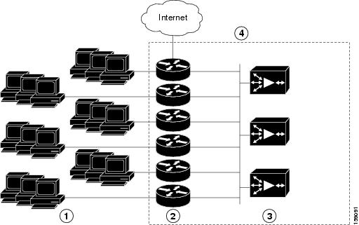
WCCP Version 2 enables a set of branch WAEs in a WAE or ANC group to connect to multiple routers. The WAEs in a group and the WCCP Version 2-enabled routers connected to the WAE group that are running the same WCCP service are known as a service group.
Through communication with the branch WAEs, the WCCP Version 2-enabled routers are aware of the available branch WAEs. Routers and branch WAEs become aware of one another and form a service group using WCCP Version 2. See Figure 5-1.
In a Cisco WAAS AppNav deployment, only the ANCs are included in the service group. The routers do not send traffic directly to the optimizing Cisco WAEs (WAAS nodes); instead, ANCs distribute traffic within the Cisco WAAS network to the optimizing WAAS nodes.
Figure 5-1 Service Groups with WCCP Version 2
|
|
|
||
|
|
|
If you have a group of branch WAEs, the WAE that is seen by all the WCCP Version 2-enabled routers, and that has the lowest IP address, becomes the lead branch WAE.
The following procedure describes how a branch WAE in a service group is designated as the lead:
1.![]() Each branch WAE is configured with a list of WCCP-enabled routers.
Each branch WAE is configured with a list of WCCP-enabled routers.
Multiple WCCP-enabled routers can service a group (up to 32 routers can be specified). Any of the available routers in a service group can redirect packets to each of the branch WAEs in the group.
2.![]() Each branch WAE announces its presence to each router on the router list. The routers reply with their view of branch WAEs in the service group.
Each branch WAE announces its presence to each router on the router list. The routers reply with their view of branch WAEs in the service group.
3.![]() After the view is consistent across all of the branch WAEs in the group, one branch WAE is designated as the lead branch WAE and sets the policy that the WCCP-enabled routers need to deploy in redirecting packets.
After the view is consistent across all of the branch WAEs in the group, one branch WAE is designated as the lead branch WAE and sets the policy that the WCCP-enabled routers need to deploy in redirecting packets.
The lead branch WAE determines how traffic should be allocated across the branch WAEs in the group. The assignment information is passed to the entire service group from the designated lead branch WAE so that the WCCP-enabled routers of the group can redirect the packets, and the branch WAEs in the group can better manage their load.
WCCP uses service groups to define WAAS services for a WCCP Version 2-enabled router and branch WAEs in a group. WCCP also redirects client requests to these groups in real time.
All the ports receiving redirected traffic that are configured as members of the same WCCP service group share the following characteristics:
- They have the same hash or mask parameters, as configured with the Cisco WAAS Central Manager (Configuring or Viewing the WCCP Settings on WAEs) or the WAAS CLI (the wccp service-number mask global configuration command).
- The WCCP Version 2 service on individual ports cannot be stopped or started individually (a WCCP Version 2 restriction).
Configuring IP Access Lists on a Router
You can optionally configure the router to redirect traffic from your WAE based on access control lists (ACLs) that you define on the router. These access lists are also referred to as redirect lists.
Note![]() We recommend that you use redirect lists on the WCCP-enabled router where possible, because that is the most efficient method to control traffic interception. However, you can also configure static bypass lists or interception ACLs on the WAEs, and of these two, we recommend that you use interception ACLs because they are more flexible and give better statistics about passed-through connections. For information about how to configure an interception ACL for a WAE, see Configuring Interception Access Control Lists. For information about how to configure a static bypass list, see Configuring Static Bypass Lists for WAEs. You can also configure interface ACLs on WAEs to control access to the WAE, as described in Chapter9, “Creating and Managing IP Access Control Lists for Cisco WAAS Devices”
We recommend that you use redirect lists on the WCCP-enabled router where possible, because that is the most efficient method to control traffic interception. However, you can also configure static bypass lists or interception ACLs on the WAEs, and of these two, we recommend that you use interception ACLs because they are more flexible and give better statistics about passed-through connections. For information about how to configure an interception ACL for a WAE, see Configuring Interception Access Control Lists. For information about how to configure a static bypass list, see Configuring Static Bypass Lists for WAEs. You can also configure interface ACLs on WAEs to control access to the WAE, as described in Chapter9, “Creating and Managing IP Access Control Lists for Cisco WAAS Devices”
Redirect lists that are configured on the routers have the highest priority, followed by static bypass lists or interception ACLs on WAEs. Interception ACLs that are configured on WAEs take precedence over application definition policies that have been defined on the WAE.
A WCCP Version 2-enabled router can be configured with access lists to permit or deny redirection of TCP traffic to a WAE. The following example shows that traffic conforming to the following criteria are not redirected by the router to the WAE:
- Originating from the host 10.1.1.1 destined for any other host
- Originating from any host destined for the host 10.255.1.1
Router(config)# ip wccp 61 redirect-list 120
Router(config)# ip wccp 62 redirect-list 120
Router(config)# access-list 120 deny ip host 10.1.1.1 any
Router(config)# access-list 120 deny ip any host 10.1.1.1
Router(config)# access-list 120 deny ip any host 10.255.1.1
Router(config)# access-list 120 deny ip host 10.255.1.1 any
Router(config)# access-list 120 permit ip any
Traffic that is not explicitly permitted is implicitly denied redirection. The access-list 120 permit ip any command explicitly permits all traffic (from any source on the way to any destination) to be redirected to the WAE. Because criteria matching occurs in the order in which the commands are entered, the global permit command is the last command entered.
To limit the redirection of packets to those packets matching an access list, use the ip wccp redirect-list global configuration command. Use this command to specify which packets should be redirected to the WAE.
When WCCP is enabled, but the ip wccp redirect-list command is not used, all the packets matching the criteria of a WCCP service are redirected to the WAE. When you specify the ip wccp redirect-list command, only packets that match the access list are redirected.
The ip wccp global configuration command and the ip wccp redirect interface configuration command are the only commands required to start redirecting requests to the WAE using WCCP. To instruct an interface on the WCCP-enabled router to check for appropriate outgoing packets and redirect them to a WAE, use the ip wccp redirect interface configuration command. If the ip wccp command is enabled, but the ip wccp redirect command is disabled, the WCCP-enabled router is aware of the WAE, but does not use it.
To specify the access list by name or number, use the ip wccp group-list global configuration command, which defines criteria for group membership. In the following example, the access-list 1 permit 10.10.10.1 command is used to define the IP address of the WAE that is allowed to join the WCCP service group:
Router(config)# ip wccp 61 group-list 1
Router(config)# ip wccp 62 group-list 1
Router(config)# access-list 1 permit 10.10.10.1

Tip![]() If you have a WCCP service farm with multiple WAEs, the load-balancing assignment may cause packets that are sent to the WAE devices themselves (such as management traffic) to be redirected to a different WAE in the farm, negatively impacting performance. To avoid this situation, we recommend that you configure a WCCP redirect list that excludes traffic that is sent to the WAE IP addresses from being redirected.
If you have a WCCP service farm with multiple WAEs, the load-balancing assignment may cause packets that are sent to the WAE devices themselves (such as management traffic) to be redirected to a different WAE in the farm, negatively impacting performance. To avoid this situation, we recommend that you configure a WCCP redirect list that excludes traffic that is sent to the WAE IP addresses from being redirected.
For more information on access lists, see the Cisco IOS IP addressing and services documentation.
Setting a Service Group Password on a Router
For security purposes, you can set a service password for your WCCP Version 2-enabled router and the WAEs that access it. Only devices configured with the correct password are allowed to participate in the WCCP service group.
From the global configuration mode of your WCCP-enabled router, enter the following commands to specify the service group password for the TCP promiscuous mode service on the router (the service IDs must match the service IDs configured on the WAE):
[0-7] password
[0-7] password
The required password argument is the string that directs the WCCP Version 2-enabled router to apply MD5 authentication to messages received from the specified service group. Messages that are not accepted by the authentication are discarded. 0-7 is the optional value that indicates the HMAC MD5 algorithm used to encrypt the password. This value is generated when an encrypted password is created for the WAE. 7 is the recommended value. The optional password argument is the optional password name that is combined with the HMAC MD5 value to create security for the connection between the router and the WAE.
For information about how to use the Cisco WAAS Central Manager to specify the service group password on a WAE, see Configuring or Viewing the WCCP Settings on WAEs.
Configuring a Loopback Interface on the Router
The highest IP address among the router’s loopback interfaces is used to identify the router to the WAEs.
The following example configures the loopback interface, exits configuration mode, and saves the running configuration to the startup configuration:
Router(config-if)# end
Router# copy running-config startup-config
Configuring Router QoS for WCCP Control Packets
Cisco WAAS sends WCCP control packets marked with a differentiated services code point (DSCP) value of 192. (In Cisco WAAS versions earlier than 4.2, packets were unmarked.) For a router to honor this priority value, you must configure the router’s multilayer switching (MLS) quality of service (QoS) port trust state and classify traffic by examining the DSCP value. To configure the router appropriately, use the mls qos trust dscp command in interface configuration mode on the interface connected to the WAE.
Configuring WCCP on WAEs
This section contains the following topics:
- About Load Balancing and WAEs
- About Packet-Forwarding Methods
- Configuring or Viewing the WCCP Settings on WAEs
- Configuring or Viewing the WCCP Settings on ANCs
- Configuring and Viewing WCCP Router Lists for WAEs
- Configuring WAEs for a Graceful Shutdown of WCCP
- Configuring Static Bypass Lists for WAEs
- Configuring Interception Access Control Lists
- Configuring Egress Methods for WCCP-Intercepted Connections
Note![]() Before you perform the procedures in this section, you should have completed an initial configuration of your Cisco WAAS network, which includes the basic configuration of WCCP Version 2 and the TCP promiscuous mode service on your routers and WAEs, as described in the Cisco Wide Area Application Services Quick Configuration Guide.
Before you perform the procedures in this section, you should have completed an initial configuration of your Cisco WAAS network, which includes the basic configuration of WCCP Version 2 and the TCP promiscuous mode service on your routers and WAEs, as described in the Cisco Wide Area Application Services Quick Configuration Guide.
About Load Balancing and WAEs
Multiple WAEs with WCCP support can be deployed for dynamic load balancing to enable adjustments to the loads being forwarded to the individual WAEs in a service group. IP packets received by a WCCP-enabled router are examined to determine if it is a request that should be directed to a WAE. Packet examination involves matching the request to a defined service criteria. These packets are passed to the processing routine on the router to determine which WAE, if any, should receive the redirected packets.
Note![]() In a WAAS AppNav deployment, only ANCs are included in the service group and are load balanced by the routers. The routers do not send traffic to the optimizing WAEs (WNGs); instead, ANCs distribute traffic to the optimizing WNGs.
In a WAAS AppNav deployment, only ANCs are included in the service group and are load balanced by the routers. The routers do not send traffic to the optimizing WAEs (WNGs); instead, ANCs distribute traffic to the optimizing WNGs.
You can use load balancing to balance the traffic load across multiple WAEs. Load balancing allows the set of hash address buckets assigned to a WAE to be adjusted, shifting the load from an overwhelmed WAE to other WAEs that have available capacity. Two assignment methods are used by this technique: hashing and masking.
Assignment method denotes the method used by WCCP to perform load distribution across WAEs. The two possible load-balancing assignment methods are hashing and masking. If the mask load-balancing method is not specified, then the hash load-balancing method, which is the default method, is used.
Note![]() In a Cisco WAAS AppNav deployment, only the mask assignment method is supported and is the default.
In a Cisco WAAS AppNav deployment, only the mask assignment method is supported and is the default.
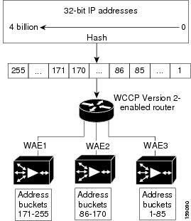
WCCP supports redirection based on a hash function. The hash key may be based on the source or destination IP address of the packet. For Cisco WAAS, load-balancing hashing is based on a source IP address (default), a destination IP address, or both.
The hash function uses the source IP address to obtain an address bucket to which the packet is assigned. These source address buckets are then mapped to a particular WAE depending on how many WAEs are present and how busy they are. (See Figure 5-2.)
Figure 5-2 Load Balancing Through Hashing of IP Addresses
Note![]() Packets that the WAEs do not service are tunneled back to the same router from which they were received. When a router receives a formerly redirected packet, it knows that it should not redirect it again.
Packets that the WAEs do not service are tunneled back to the same router from which they were received. When a router receives a formerly redirected packet, it knows that it should not redirect it again.
Destination IP address hashing guarantees that a single WAE caches a given file server. This method, which allows a local coherency directive to be safely applied to the file server content (provided that no other collaboration on the content occurs), improves performance and WAN link and disk utilization. This method may distribute the load unevenly because of uneven activity on a file server.
Source IP address hashing has better potential for session distribution between the caches on branch WAEs. This method may impact performance and WAN link and disk utilization (see the previous description of factors to be aware of when load balancing is applied). Also, any change in the IP address of a client (which can happen when working in DHCP environments) may cause the client to switch to another branch WAE, which can cause the client to experience reduced performance until the client’s working set is retrieved into the new cache.
Hashing that is based on a client IP address does not guarantee any locality of the hash key. For example, clients from the same subnet (which are likely to share and collaborate on the same content) may be assigned two different hash numbers and may be redirected to different branch WAEs, while clients from different subnets may be assigned the same hash number and may be redirected to the same branch WAE. Hashing that is based on a client IP address does guarantee consistency. For example, a client using the same IP address is redirected to the same branch WAE.
In the service farm, a lead WAE is chosen to build the hash table that distributes the load between the available WAEs. The lead WAE distributes the buckets evenly. The source IP address is hashed and the resulting bucket determines the WAE that will handle the packet.
WCCP supports redirection by mask value assignments. This method relies on masking to make redirection decisions. The decisions are made using special hardware support in the WCCP-enabled router. This method can be very efficient because packets are switched by the hardware.
Note![]() The masking method can only be used for load balancing with the Catalyst 3750, Catalyst 4500, and Catalyst 6500 Series Switches, Cisco 7600 Series Routers, and Cisco ASR 1000 Aggregation Series Routers. And, the masking method can be used with the Cisco 2800, 3800, and 7200 Series Routers when they are running Cisco IOS Release 12.4(20)T or later releases.
The masking method can only be used for load balancing with the Catalyst 3750, Catalyst 4500, and Catalyst 6500 Series Switches, Cisco 7600 Series Routers, and Cisco ASR 1000 Aggregation Series Routers. And, the masking method can be used with the Cisco 2800, 3800, and 7200 Series Routers when they are running Cisco IOS Release 12.4(20)T or later releases.
You must explicitly specify masking. You can specify two mask values based on the source or destination IP address of the packet. For Cisco WAAS, the default mask value is based on the source IP address. You can enable masks by using the default values or specifying a particular mask. The default mask values, specified in hexadecimal notation, are as follows:
You can specify the mask value with a maximum of seven bits. The WAE creates a table of the 27 (or 128) combinations, assigns the WAE IP addresses to them, and sends this table to a WCCP-enabled router. The router uses this table to distribute the traffic among all the WAEs that are in the service group. Each packet that matches the WCCP service parameters is compared to this table and the packets are sent to the matching WAE.
In a service farm where the WAEs have different masks, the first WAE to establish two-way communication with the routers determines the farm’s mask. All the other WAEs cannot join the farm unless they are configured with the same mask.
Masking is typically used at the data center, where you can take advantage of the hardware-accelerated WCCP redirection capabilities of switches, such as the Catalyst 6500 Series Switches. At the data center, the load balancing goal should be to have all the connections originating from a given client subnet (typically equivalent to a branch) go to one data center WAE, in order to improve data redundancy elimination (DRE) compression performance. Also, mask assignment on the Catalyst 6500 series switches uses the ACL Ternary Content Adjustable Memory (TCAM). When combined with WCCP redirect lists, mask assignment can use a large portion of the TCAM. To minimize TCAM usage, use a mask with fewer care bits.
Given these considerations, for Cisco WAAS Version 4.2.1 and later, the default mask has been changed from src-ip-mask 0x1741 and dst-ip-mask 0x0 (in 4.1x versions) to src-ip-mask 0xF00 and dst-ip-mask 0x0 (in 4.2.1 and later versions). The current source IP mask uses only four care bits rather than the six care bits used by the old mask.
With a typical data center WCCP interception configuration (ingress interception with service 61 on the WAN, ingress interception with service 62 on the LAN), this mask load balances /24 branch subnets (it extracts the last 4 bits of /24 subnets). Connections from one branch subnet will be pinned to one data center WAE. If your network has a different distribution of IP addresses, for example, /16 subnets, you should configure a mask that extracts bits from the /16 network part of the address, for example, src-ip-mask 0xF0000. Similarly, if some branches generate more traffic than others, you may want to create a mask that also extracts bits from the host part of the address, for example, 0xF03.
About Packet-Forwarding Methods
A WCCP-enabled router redirects intercepted TCP segments to a WAE using one of the following two packet-forwarding methods:
- Generic routing encapsulation (GRE): Allows packets to reach the WAE, irrespective of the number of routers in the path to the WAE.
- Layer 2 redirection: Allows packets to be switched at Layer 2 (MAC layer) and reach the WAE.
Table 5-3 describes the packet-forwarding methods.
The redirection mode is controlled by the branch WAE. The first branch WAE that joins the WCCP service group decides the forwarding method (GRE or Layer 2 redirection) and the assignment method (hashing or masking). The term mask assignment refers to WCCP Layer 2 Policy Feature Card 2 (PFC2) input redirection.
If masking is selected with WCCP output redirection, the branch WAE falls back to the original hardware acceleration that is used with the Multilayer Switch Feature Card (MSFC) and the Policy Feature Card (PFC).
For example, WCCP filters the packets to determine which redirected packets have been returned from the branch WAE and which ones have not. WCCP does not redirect the ones that have been returned because the branch WAE has determined that the packets should not be processed. WCCP Version 2 returns the packets that the branch WAE does not service to the same router from which they were transmitted.
Reasons for Packet Rejection and Return
A branch WAE rejects packets and initiates packet return for the following reasons:
- The WAE is filtering out certain conditions that make processing packets unproductive, for example, when IP authentication has been turned on.
- You have configured a static bypass list or interception ACL on the branch WAE.
Note![]() The packets are redirected to the source of the connection between the WCCP-enabled router and the branch WAE. Depending on the Cisco IOS software version used, this source could be either the address of the outgoing interface or the router IP address. In the latter case, it is important that the branch WAE has the IP address of the WCCP-enabled router stored in the router list. For more information on router lists, see Configuring and Viewing WCCP Router Lists for WAEs.
The packets are redirected to the source of the connection between the WCCP-enabled router and the branch WAE. Depending on the Cisco IOS software version used, this source could be either the address of the outgoing interface or the router IP address. In the latter case, it is important that the branch WAE has the IP address of the WCCP-enabled router stored in the router list. For more information on router lists, see Configuring and Viewing WCCP Router Lists for WAEs.
Cisco Express Forwarding (CEF) is required for WCCP and must be enabled on the router.
WCCP also allows you to configure multiple routers in a router list to support a particular WCCP service (for example, SMB redirection).
Layer 3 GRE as a Packet-Forwarding Method
A WCCP-enabled router redirects intercepted requests to a WAE, and can encapsulate packets using GRE. This method of forwarding packets allows packets to reach the WAE even if there are routers in the path to the WAE. Packet redirection is handled entirely by the router software.
GRE allows datagrams to be encapsulated into IP packets at the WCCP-enabled router and then redirected to a WAE (the transparent proxy server). At this intermediate destination, the datagrams are decapsulated and then handled by the Cisco WAAS software. If the request cannot be handled locally, the origin server may be contacted by the associated WAE to complete the request. In doing so, the trip to the origin server appears to the inner datagrams as one hop. The redirected traffic using GRE is usually referred to as GRE tunnel traffic. With GRE, all redirection is handled by the router software.
With WCCP redirection, a Cisco router does not forward the TCP SYN packet to the destination because the router has WCCP enabled on the destination port of the connection. Instead, the WCCP-enabled router encapsulates the packet using GRE tunneling and sends it to the WAE that has been configured to accept redirected packets from this WCCP-enabled router.
After receiving the redirected packet, the WAE performs the following tasks:
1.![]() Strips the GRE layer from the packet.
Strips the GRE layer from the packet.
2.![]() Decides whether it should accept this redirected packet and process the request for content or deny the redirected packet as follows:
Decides whether it should accept this redirected packet and process the request for content or deny the redirected packet as follows:
–![]() If the WAE decides to accept the request, it sends a TCP SYN ACK packet to the client. In this response packet, the WAE uses the IP address of the original destination (origin server) that was specified as the source address so that the WAE can be invisible (transparent) to the client; it pretends to be the destination that the TCP SYN packet from the client was trying to reach.
If the WAE decides to accept the request, it sends a TCP SYN ACK packet to the client. In this response packet, the WAE uses the IP address of the original destination (origin server) that was specified as the source address so that the WAE can be invisible (transparent) to the client; it pretends to be the destination that the TCP SYN packet from the client was trying to reach.
–![]() If the WAE decides not to accept the request, it re-encapsulates the TCP SYN packet in GRE, and sends it back to the WCCP-enabled router. The router understands that the WAE is not interested in this connection and forwards the packet to its original destination (that is, the origin server).
If the WAE decides not to accept the request, it re-encapsulates the TCP SYN packet in GRE, and sends it back to the WCCP-enabled router. The router understands that the WAE is not interested in this connection and forwards the packet to its original destination (that is, the origin server).
Layer 2 Redirection as a Packet-Forwarding Method
Layer 2 redirection is accomplished when a WCCP-enabled router or switch takes advantage of internal switching hardware that either partially or fully implements the WCCP traffic interception and redirection functions at Layer 2. This type of redirection is currently supported only with the Catalyst 6500 Series Switches and Cisco 7200 and 7600 Series Routers. With Layer 2 redirection, the first redirected traffic packet is handled by the router software. The rest of the traffic is handled by the router hardware. The branch WAE instructs the router or switch to apply a bit mask to certain packet fields, which in turn provides a mask result or index mapped to the branch WAE in the service group in the form of a mask index address table. The redirection process is accelerated in the switching hardware, making Layer 2 redirection more efficient than Layer 3 GRE.
Note![]() WCCP is licensed only on the WAE and not on the redirecting router. WCCP does not interfere with normal router or switch operations.
WCCP is licensed only on the WAE and not on the redirecting router. WCCP does not interfere with normal router or switch operations.
Configuring or Viewing the WCCP Settings on WAEs
This section describes how to configure or view WCCP settings on WAEs that are configured as application accelerators and are not part of an AppNav Cluster (WAEs that are part of an AppNav Cluster use only the appnav-controller interception method). To configure or view the WCCP settings on WAEs configured as AppNav Controllers, see Configuring or Viewing the WCCP Settings on ANCs.
Device group configuration is not possible beginning with Cisco WAAS version 5.0. However, you can use the Copy Settings taskbar icon in the configuration window to copy the settings to other devices in your network. To ensure consistency, we recommend that you copy the same WCCP settings to all devices in the same WCCP service farm.
Note![]() Before you perform the procedure in this section, you should have already completed a basic WCCP configuration for your Cisco WAAS network that includes the configuration of the TCP promiscuous mode service, as described in the Cisco Wide Area Application Services Quick Configuration Guide.
Before you perform the procedure in this section, you should have already completed a basic WCCP configuration for your Cisco WAAS network that includes the configuration of the TCP promiscuous mode service, as described in the Cisco Wide Area Application Services Quick Configuration Guide.
To modify the WCCP settings for a WAE, follow these steps:
Step 1![]() From the Cisco WAAS Central Manager menu, choose Devices > device-name.
From the Cisco WAAS Central Manager menu, choose Devices > device-name.
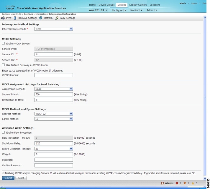
Step 2![]() Choose Configure > Interception > Interception Configuration. The Interception Configuration window appears. (See Figure 5-3.)
Choose Configure > Interception > Interception Configuration. The Interception Configuration window appears. (See Figure 5-3.)
Note![]() If you are configuring a device using a Cisco WAAS version earlier than 5.0, choose Configure > Interception > WCCP > Settings to configure WCCP settings. The Interception Configuration window looks different, but has similar settings.
If you are configuring a device using a Cisco WAAS version earlier than 5.0, choose Configure > Interception > WCCP > Settings to configure WCCP settings. The Interception Configuration window looks different, but has similar settings.
Figure 5-3 Interception Configuration Window for WAE
Step 3![]() Check the current settings for the chosen device:
Check the current settings for the chosen device:
- To keep the current settings and to close the window, click Reset.
- To remove the current settings, click the Remove Settings taskbar icon.
- To modify the current settings, change the current setting, as described in the rest of this procedure.
- To copy the settings to other WAEs in your network, click the Copy Settings taskbar icon.
The Copy Interception Settings window opens, where you can select other WAEs to which the interception settings can be copied. You can copy all the settings or you can exclude the router list and enable the WCCP service.
Step 4![]() To copy the settings to the selected WAEs, click OK.
To copy the settings to the selected WAEs, click OK.
By default, WCCP is disabled on a WAE. However, as part of the initial configuration of WCCP in your Cisco WAAS network, you should have enabled WCCP Version 2 on your WAEs (the branch WAE and the data center WAE) as well as on the routers in the data center and branch office that will be transparently redirecting requests to these WAEs. For information about how to perform a basic WCCP configuration in your WAAS network, see the Cisco Wide Area Application Services Quick Configuration Guide.
Step 5![]() From the Interception Method drop-down list, choose WCCP to enable the WCCP interception method. If you change this setting from any setting other than None, click Submit to update the window with the proper fields for configuring WCCP. (The Interception Method drop-down list is not displayed for devices using a Cisco WAAS version earlier than Cisco WAAS Version earlier than 5.0.)
From the Interception Method drop-down list, choose WCCP to enable the WCCP interception method. If you change this setting from any setting other than None, click Submit to update the window with the proper fields for configuring WCCP. (The Interception Method drop-down list is not displayed for devices using a Cisco WAAS version earlier than Cisco WAAS Version earlier than 5.0.)
Step 6![]() Check the Enable WCCP Service check box to enable WCCP Version 2 on the chosen device, or uncheck the check box to disable WCCP on the chosen device.
Check the Enable WCCP Service check box to enable WCCP Version 2 on the chosen device, or uncheck the check box to disable WCCP on the chosen device.
Note![]() Ensure that the routers used in the WCCP environment are running a version of the Cisco IOS software that also supports the WCCP Version 2.
Ensure that the routers used in the WCCP environment are running a version of the Cisco IOS software that also supports the WCCP Version 2.
Note![]() If you use the Cisco WAAS Central Manager to disable WCCP on a WAAS device, the Cisco WAAS Central Manager immediately shuts down WCCP and closes any existing connections, ignoring the setting configured by the wccp shutdown max-wait global configuration command. To gracefully shut down WCCP connections, use the no enable WCCP configuration command on the Cisco WAAS device.
If you use the Cisco WAAS Central Manager to disable WCCP on a WAAS device, the Cisco WAAS Central Manager immediately shuts down WCCP and closes any existing connections, ignoring the setting configured by the wccp shutdown max-wait global configuration command. To gracefully shut down WCCP connections, use the no enable WCCP configuration command on the Cisco WAAS device.
Step 7![]() In the Service ID1 field, specify the first service ID of the WCCP service pair. After you submit, the Service ID2 field is filled in with the second service ID of the pair, which is one greater than Service ID1.
In the Service ID1 field, specify the first service ID of the WCCP service pair. After you submit, the Service ID2 field is filled in with the second service ID of the pair, which is one greater than Service ID1.
- For WAEs with Cisco WAAS Version 4.4.1 or later, you can change the WCCP service IDs from the default of 61/62 to a different pair of numbers, which allows a router to support multiple WCCP farms because the WAEs in different farms can use different service IDs. (The Service ID fields are not shown for devices using Cisco WAAS versions earlier than Cisco WAAS Version 4.4 and the service IDs are fixed at 61/21.)
- The router service priority varies inversely with the service ID. The service priority of the default service IDs 61/62 is 34. If you specify a lower service ID, the service priority is higher than 34; if you specify a higher service ID, the service priority is lower than 34.
Step 8![]() Check the Use Default Gateway as WCCP Router check box to use the default gateway of the WAE device as the router to associate with the WCCP TCP promiscuous mode service.
Check the Use Default Gateway as WCCP Router check box to use the default gateway of the WAE device as the router to associate with the WCCP TCP promiscuous mode service.
The Cisco WAAS Central Manager assigns the router list number, which is displayed next to the router list field after the page is submitted. As part of the initial configuration of your Cisco WAAS network, you may have already created a WCCP router list with the setup utility, as described in the Cisco Wide Area Application Services Quick Configuration Guide. For more information about WCCP router lists, see Configuring and Viewing WCCP Router Lists for WAEs.
Note![]() Checking or unchecking the Use Default Gateway as WCCP Router check box, changing the router list, or submitting the WCCP page removes existing router lists, if any, that are not assigned to the WCCP service, including router lists configured by the setup utility or through the CLI.
Checking or unchecking the Use Default Gateway as WCCP Router check box, changing the router list, or submitting the WCCP page removes existing router lists, if any, that are not assigned to the WCCP service, including router lists configured by the setup utility or through the CLI.
Step 9![]() (Optional) To force WCCP to use only the configured assignment method, check the Only Use Selected Assignment Method check box. You can specify only one load-balancing method (hashing or masking) per WCCP service in a branch WAE service group. (This check box is shown only for devices using a Cisco WAAS Version earlier than Cisco WAAS Version 4.4.)
(Optional) To force WCCP to use only the configured assignment method, check the Only Use Selected Assignment Method check box. You can specify only one load-balancing method (hashing or masking) per WCCP service in a branch WAE service group. (This check box is shown only for devices using a Cisco WAAS Version earlier than Cisco WAAS Version 4.4.)
Note![]() If you check the Only Use Selected Assignment Method check box, the WAE only joins a WCCP farm if the assignment method configured on the WAE is supported by the router. If you do not check the Only Use Selected Assignment Method check box, the WAE uses the assignment method that the router supports, even if the WAE is configured differently from the router.
If you check the Only Use Selected Assignment Method check box, the WAE only joins a WCCP farm if the assignment method configured on the WAE is supported by the router. If you do not check the Only Use Selected Assignment Method check box, the WAE uses the assignment method that the router supports, even if the WAE is configured differently from the router.
Step 10![]() (Optional) From the Assignment Method drop-down list, choose the type of WAE load-balancing assignment method to use:
(Optional) From the Assignment Method drop-down list, choose the type of WAE load-balancing assignment method to use:
- Choose Hash to use the hash method (the default for devices using a Cisco WAAS version earlier than Cisco WAAS Version 5.0). Perform Step 11 and Step 12 to define how the hash works, and skip to Step 14 because the mask settings are not used.
- Choose Mask to use the mask method (the default for devices using Cisco WAAS Version 5.0 or later). Skip to Step 13 to define the service mask.
For more information, see About Load Balancing and WAEs.
Step 11![]() (Optional) To define the load-balancing hash for WCCP service ID1 on the source IP address, check the Hash on Source IP check box. This check box is shown only if the hash assignment method is used.
(Optional) To define the load-balancing hash for WCCP service ID1 on the source IP address, check the Hash on Source IP check box. This check box is shown only if the hash assignment method is used.
Step 12![]() (Optional) To define the load-balancing hash for WCCP service ID1 on the destination IP address, check the Hash on Destination IP check box. This check box is shown only if the hash assignment method is used.
(Optional) To define the load-balancing hash for WCCP service ID1 on the destination IP address, check the Hash on Destination IP check box. This check box is shown only if the hash assignment method is used.
Step 13![]() (Optional) To use a custom service mask, enter different mask values in the WCCP Assignment Settings for Load Balancing area, overwriting the default mask settings. If you do not change these settings, the defaults are used. Define the custom mask as follows:
(Optional) To use a custom service mask, enter different mask values in the WCCP Assignment Settings for Load Balancing area, overwriting the default mask settings. If you do not change these settings, the defaults are used. Define the custom mask as follows:
- In the Source IP Mask field, specify the IP address mask defined by a hexadecimal number, for example, FE000000, used to match the packet source IP address. The range is 00000000 to FE000000. The default is F00.
- In the Destination IP Mask field, specify the IP address mask defined by a hexadecimal number, for example, FE000000, used to match the packet destination IP address. The range is 0000000 to FE000000. The default is 0.
Note![]() If you apply the default mask to a WAE running Cisco WAAS Version 4.1.x or earlier, the mask is different from the default mask (0x1741) set under Cisco WAAS Version 4.1.x and earlier.
If you apply the default mask to a WAE running Cisco WAAS Version 4.1.x or earlier, the mask is different from the default mask (0x1741) set under Cisco WAAS Version 4.1.x and earlier.
If the WAE detects that its configured mask is not the same as that advertised by one or more routers in the farm, it is not allowed to join the farm, and a major alarm is raised (Configured mask mismatch for WCCP). This alarm can occur when a WAE is trying to join a farm that already has other WAEs, and these other WAEs are configured with a different mask. The routers do not allow other WAEs to join the farm unless they advertise the same mask. To correct this alarm, ensure that all the WAEs in the farm are configured with the same mask. This alarm is cleared when the WAE’s configured mask matches the mask of all the routers in the farm.
Step 14![]() From the Redirect Method drop-down list, choose the type of packet redirection (forwarding) method to use:
From the Redirect Method drop-down list, choose the type of packet redirection (forwarding) method to use:
- WCCP GRE (the default for devices using a Cisco WAAS version earlier than Cisco WAAS Version 5.0) to use Layer 3 GRE packet redirection.
- WCCP L2 (the default for devices using Cisco WAAS Version 5.0 or later) to permit the WAE to receive transparently redirected traffic from a WCCP Version 2-enabled switch or router if the WAE has a Layer 2 connection with the device and the device is configured for Layer 2 redirection. For more information, see About Packet-Forwarding Methods.
Note![]() Do not use WCCP L2 redirection on an ISR-WAAS device when ip unnumbered is configured on the host router VirtualPortGroup interface. The device will not be able to join the WCCP farm and the missing_assignment alarm will be raised.
Do not use WCCP L2 redirection on an ISR-WAAS device when ip unnumbered is configured on the host router VirtualPortGroup interface. The device will not be able to join the WCCP farm and the missing_assignment alarm will be raised.
Step 15![]() From the Return Method drop-down list, choose the type of method to use to return nonoptimized (bypassed) packets to the router:
From the Return Method drop-down list, choose the type of method to use to return nonoptimized (bypassed) packets to the router:
The Return Method drop-down list is shown only for devices using a Cisco WAAS version earlier than Cisco WAAS Version 5.0.
- For Cisco WAAS Version 5.1, the return method is set the same as the redirect method.
- For Cisco WAAS Version 5.2 and later, the return method is automatically negotiated with router to the same as the redirect method if the router supports it.
- If the router does not support the return method that matches the redirect method, then the return method is set to the return method supported by the router.
For example, if the redirect method is set to WCCP L2, but the router supports only the GRE return method, then the return method is set to WCCP GRE.
Step 16![]() (Optional) From the Egress Method drop-down list, choose the method to use to return optimized packets to the router or switch:
(Optional) From the Egress Method drop-down list, choose the method to use to return optimized packets to the router or switch:
For devices using a Cisco WAAS version earlier than Cisco WAAS Version 5.0, the choices are as follows: IP Forwarding (default), WCCP Negotiated Return, or Generic GRE. For more details on choosing the egress method, see Configuring Egress Methods for WCCP-Intercepted Connections.
Step 17![]() (Optional) Modify the current advanced settings in the Advanced WCCP Settings area as follows:
(Optional) Modify the current advanced settings in the Advanced WCCP Settings area as follows:
- Check the Enable Flow Protection check box to keep the TCP flow intact and to avoid overwhelming the device when it comes up or is reassigned new traffic. Flow protection is disabled by default.
- In the Flow Protection Timeout field, specify the amount of time, in seconds, that flow protection should be enabled. The default is 0, which means it stays enabled with no timeout. (The Flow Protection Timeout field is not shown for devices using a Cisco WAAS version earlier than Cisco WAAS Version 5.0.)
Note![]() The Enable Flow Protection check box and the Flow Protection Timeout field are not enabled on Cisco WAAS Version 6.0.1.
The Enable Flow Protection check box and the Flow Protection Timeout field are not enabled on Cisco WAAS Version 6.0.1.
The WAE does not reboot until either all connections have been serviced or the maximum wait time (specified through this Shutdown Delay field) has elapsed for WCCP.
The default value of 30 seconds is the only value supported on Cisco WAAS versions earlier than Cisco WAAS Version 4.4.1. (The Failure Detection Timeout field is not shown for devices using a Cisco WAAS Version earlier than Cisco WAAS Version 4.4.)
The failure detection timeout value is negotiated with the router and takes effect only if the router also has the variable timeout capability. If the router has a fixed timeout of 30 seconds and you have configured a failure detection value on the WAE other than the default 30 seconds, the WAE is not able to join the farm and the following alarm is raised: Router unusable with a reason of Timer interval mismatch with router.
–![]() If the total of all the weight values of the WAEs in a service group is less than or equal to 100, then the weight value represents a literal percentage of the total load redirected to the device for load-balancing purposes.
If the total of all the weight values of the WAEs in a service group is less than or equal to 100, then the weight value represents a literal percentage of the total load redirected to the device for load-balancing purposes.
A WAE with a weight of 10 receives 10 percent of the total load in a service group where the total of all the weight values is 50. If a WAE in such a service group fails, the other WAEs still receive the same load percentages as before the failure; they will not receive the load allocated to the failed WAE.
–![]() If the total of all the weight values of the WAEs in a service group is between 101 and 10000, then the weight value is treated as a fraction of the total weight of all the active WAEs in the service group.
If the total of all the weight values of the WAEs in a service group is between 101 and 10000, then the weight value is treated as a fraction of the total weight of all the active WAEs in the service group.
A WAE with a weight of 200 receives 25 percent of the total load in a service group where the total of all the weight values is 800. If a WAE in such a service group fails, the other WAEs will receive the load previously allocated to the failed WAE. The failover handling is different than if the total weights are less than or equal to 100.
–![]() By default, weights are not assigned and the traffic load is distributed evenly between the WAEs in a service group.
By default, weights are not assigned and the traffic load is distributed evenly between the WAEs in a service group.
a.![]() Specify the password to be used for secure traffic between the WAEs within a cluster and the router for a specified service.
Specify the password to be used for secure traffic between the WAEs within a cluster and the router for a specified service.
–![]() Passwords must not exceed eight characters in length. Do not use the following characters: space, backwards single quote (`), double quote ("), pipe (|), or question mark (?).
Passwords must not exceed eight characters in length. Do not use the following characters: space, backwards single quote (`), double quote ("), pipe (|), or question mark (?).
–![]() Be sure to enable all other WAEs and routers within the cluster with the same password.
Be sure to enable all other WAEs and routers within the cluster with the same password.
b.![]() Re-enter the password in the Confirm Password field.
Re-enter the password in the Confirm Password field.
For information about how to use the Cisco WAAS CLI to specify the service group password on a router, see Setting a Service Group Password on a Router.
Step 18![]() To save the settings, click Submit.
To save the settings, click Submit.
To configure WCCP settings from the Cisco WAAS CLI, you must first set the interception method to WCCP by using the interception-method global configuration command, after which you can use the wccp router-list, wccp shutdown, and wccp tcp-promiscuous global configuration commands.
For more information about a graceful shut down of WCCP Version 2 on WAEs, see Configuring WAEs for a Graceful Shutdown of WCCP.
Configuring or Viewing the WCCP Settings on ANCs
This section describes how to configure or view WCCP settings on Cisco WAAS devices configured as AppNav Controllers (ANCs). Typically, you configure ANCs and their settings through the AppNav Clusters window in the Central Manager, which includes WCCP settings. Therefore, you do not have to configure the WCCP settings outside the AppNav Cluster context, as described in this section.
To configure or view the WCCP settings on WAEs configured as application accelerators, see Configuring or Viewing the WCCP Settings on WAEs. To configure interception settings on WAEs operating as WAAS nodes for an AppNav Controller, see If you see an entry without a check mark in the Mutual Pair column (like the third one in the figure), it indicates a WAE on which a serial peer is configured, but the peer is not similarly configured with the first device as its serial peer.Configuring Cisco AppNav Interception.
Device group configuration is not possible beginning with Cisco WAAS Version 5.0. However, you can use the Copy Settings taskbar icon in the Interception Configuration window to copy the settings to other devices in your network. To ensure consistency, we recommend that you copy the same WCCP settings to all the devices in the same WCCP service farm.
To modify the WCCP settings for an ANC, follow these steps:
Step 1![]() From the Cisco WAAS Central Manager menu, choose Devices > device-name.
From the Cisco WAAS Central Manager menu, choose Devices > device-name.
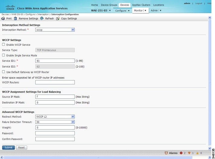
Step 2![]() Choose Configure > Interception > Interception Configuration. The Interception Configuration window appears. (See Figure 5-4.)
Choose Configure > Interception > Interception Configuration. The Interception Configuration window appears. (See Figure 5-4.)
Figure 5-4 Interception Configuration Window for ANC
Step 3![]() Check the current settings for the chosen device:
Check the current settings for the chosen device:
- To keep the current settings and to close the window, click Reset.
- To remove the current settings, click the Remove Settings taskbar icon.
- To modify the current settings, change the current setting, as described in the rest of this procedure.
- To copy the settings to other WAEs in your network, click the Copy Settings taskbar icon.
The Copy Interception Settings window opens, where you can select other WAEs to which the interception settings can be copied. You can copy all the settings or you can exclude the router list and enable the WCCP service. Click OK to copy the settings to the selected WAEs devices.
By default, WCCP is disabled on a WAE. However, as part of the initial configuration of WCCP in your Cisco WAAS network, you should have enabled WCCP Version 2 on your WAEs (the branch WAE and the data center WAE) as well as on the routers in the data center and branch office that will be transparently redirecting requests to these WAEs. For information about how to perform a basic WCCP configuration in your WAAS network, see the Cisco Wide Area Application Services Quick Configuration Guide.
Step 4![]() From the Interception Method drop-down list, choose wccp to enable the WCCP interception method. If you change this setting from any setting other than None, click Submit to update the window with the proper fields for configuring WCCP.
From the Interception Method drop-down list, choose wccp to enable the WCCP interception method. If you change this setting from any setting other than None, click Submit to update the window with the proper fields for configuring WCCP.
Step 5![]() Check the Enable WCCP Service check box to enable WCCP Version 2 on the chosen device, or uncheck the check box to disable WCCP on the chosen device.
Check the Enable WCCP Service check box to enable WCCP Version 2 on the chosen device, or uncheck the check box to disable WCCP on the chosen device.
Note![]() Ensure that the routers used in the WCCP environment are running a version of the Cisco IOS software that also supports WCCP Version 2.
Ensure that the routers used in the WCCP environment are running a version of the Cisco IOS software that also supports WCCP Version 2.
Note![]() If you use the Cisco WAAS Central Manager to disable WCCP on a Cisco WAAS device, the Cisco WAAS Central Manager immediately shuts down WCCP and closes existing connections, if any, ignoring the setting configured by the wccp shutdown max-wait global configuration command. To gracefully shut down WCCP connections, use the no enable WCCP configuration command on the Cisco WAAS device.
If you use the Cisco WAAS Central Manager to disable WCCP on a Cisco WAAS device, the Cisco WAAS Central Manager immediately shuts down WCCP and closes existing connections, if any, ignoring the setting configured by the wccp shutdown max-wait global configuration command. To gracefully shut down WCCP connections, use the no enable WCCP configuration command on the Cisco WAAS device.
Step 6![]() (Optional) Enable single service mode by checking the Enable Single Service Mode check box (the default). Single service mode simplifies configuration by using the same service ID for incoming and outgoing traffic, which is possible only with an AppNav deployment because it can handle asymmetric traffic flows.
(Optional) Enable single service mode by checking the Enable Single Service Mode check box (the default). Single service mode simplifies configuration by using the same service ID for incoming and outgoing traffic, which is possible only with an AppNav deployment because it can handle asymmetric traffic flows.
Step 7![]() In the Service ID1 field, specify the service ID of the WCCP service.
In the Service ID1 field, specify the service ID of the WCCP service.
If the Enable Single Service Mode check box is unchecked, a pair of WCCP service IDs are required, and the Service ID2 field is filled in with the second service ID of the pair, which is one greater than Service ID1. The default service IDs are 61 and 62. You can change the WCCP service IDs from the default of 61/62 to a different pair of numbers, which allows a router to support multiple WCCP farms because the ANCs in different farms can use different service IDs.
The router service priority varies inversely with the service ID. The service priority of the default service IDs 61/62 is 34. If you specify a lower service ID, the service priority is higher than 34; if you specify a higher service ID, the service priority is lower than 34.
Step 8![]() Check the Use Default Gateway as WCCP Router check box to use the default gateway of the WAE device as the router to associate with the WCCP TCP promiscuous mode service. Alternatively, you can uncheck this check box and specify a list of one more routers by their IP addresses, separated by spaces. The Central Manager assigns the router list number, which is displayed next to the router list field after the page is submitted. As part of the initial configuration of your Cisco WAAS network, you may have already created a WCCP router list with the setup utility, as described in the Cisco Wide Area Application Services Quick Configuration Guide. For more information about WCCP router lists, see Configuring and Viewing WCCP Router Lists for WAEs.
Check the Use Default Gateway as WCCP Router check box to use the default gateway of the WAE device as the router to associate with the WCCP TCP promiscuous mode service. Alternatively, you can uncheck this check box and specify a list of one more routers by their IP addresses, separated by spaces. The Central Manager assigns the router list number, which is displayed next to the router list field after the page is submitted. As part of the initial configuration of your Cisco WAAS network, you may have already created a WCCP router list with the setup utility, as described in the Cisco Wide Area Application Services Quick Configuration Guide. For more information about WCCP router lists, see Configuring and Viewing WCCP Router Lists for WAEs.
Note![]() Checking or unchecking the Use Default Gateway as WCCP Router check box, changing the router list, or submitting the WCCP page removes existing router lists, if any, that are not assigned to the WCCP service, including router lists configured by the setup utility or through the CLI.
Checking or unchecking the Use Default Gateway as WCCP Router check box, changing the router list, or submitting the WCCP page removes existing router lists, if any, that are not assigned to the WCCP service, including router lists configured by the setup utility or through the CLI.
Step 9![]() (Optional) To use a custom service mask, enter different mask values in the WCCP Assignment Settings for Load Balancing area, overwriting the default mask settings. If you do not change these settings, the defaults are used. Define the custom mask as follows:
(Optional) To use a custom service mask, enter different mask values in the WCCP Assignment Settings for Load Balancing area, overwriting the default mask settings. If you do not change these settings, the defaults are used. Define the custom mask as follows:
- In the Source IP Mask field, specify the IP address mask defined by a hexadecimal number, for example, FE000000, used to match the packet source IP address. The range is 00000000 to FE000000. The default is F.
- In the Destination IP Mask field, specify the IP address mask defined by a hexadecimal number, for example, FE000000, used to match the packet destination IP address. The range is 0000000 to FE000000. The default is 0.
For more information, see About Load Balancing and WAEs.
If the WAE detects that its configured mask is not the same as advertised by one or more routers in the farm, it is not allowed to join the farm and a major alarm is raised ( Configured mask mismatch for WCCP). This alarm can occur when a WAE is trying to join a farm that already has other WAEs, and these other WAEs are configured with a different mask. The routers do not allow other WAEs to join the farm unless they advertise the same mask. To correct this alarm, ensure that all the WAEs in the farm are configured with the same mask. This alarm is cleared when the WAE’s configured mask matches the mask of all the routers in the farm.
Step 10![]() (Optional) Modify the current advanced settings in the Advanced WCCP Settings area as follows:
(Optional) Modify the current advanced settings in the Advanced WCCP Settings area as follows:
a.![]() From the Redirect Method drop-down list, choose the type of packet redirection (forwarding) method to use:
From the Redirect Method drop-down list, choose the type of packet redirection (forwarding) method to use:
–![]() WCCP GRE to use Layer 3 GRE packet redirection.
WCCP GRE to use Layer 3 GRE packet redirection.
–![]() WCCP L2 (the default) to permit the WAE to receive transparently redirected traffic from a WCCP Version 2-enabled switch or router if the WAE has a Layer 2 connection with the device and the device is configured for Layer 2 redirection. For more information, see About Packet-Forwarding Methods.
WCCP L2 (the default) to permit the WAE to receive transparently redirected traffic from a WCCP Version 2-enabled switch or router if the WAE has a Layer 2 connection with the device and the device is configured for Layer 2 redirection. For more information, see About Packet-Forwarding Methods.
The return method is set the same as the redirect method. The return method is generic GRE when the WCCP GRE redirect method is chosen or WCCP L2 return when the WCCP L2 redirect method is chosen.
b.![]() In the Failure Detection Timeout drop-down list, choose the failure detection timeout value (3, 6, 9, 15, or 30 seconds). The default is 30 seconds and is the only value supported on Cisco WAAS versions prior to 4.4.1. This failure detection value determines how long it takes the router to detect a WAE failure.
In the Failure Detection Timeout drop-down list, choose the failure detection timeout value (3, 6, 9, 15, or 30 seconds). The default is 30 seconds and is the only value supported on Cisco WAAS versions prior to 4.4.1. This failure detection value determines how long it takes the router to detect a WAE failure.
The failure detection timeout value is negotiated with the router and takes effect only if the router also has the variable timeout capability. If the router has a fixed timeout of 30 seconds and you have configured a failure detection value on the WAE other than the default 30 seconds, the WAE is not able to join the farm and an alarm is raised ( Router unusable with a reason of Timer interval mismatch with router).
c.![]() In the Weight field, specify the weight value that is used for load balancing. The weight value ranges from 0 to 10000. If the total of all the weight values of the WAEs in a service group is less than or equal to 100, then the weight value represents a literal percentage of the total load redirected to the device for load-balancing purposes. For example, a WAE with a weight of 10 receives 10 percent of the total load in a service group where the total of all weight values is 50. If a WAE in such a service group fails, the other WAEs still receive the same load percentages as before the failure; they will not receive the load allocated to the failed WAE.
In the Weight field, specify the weight value that is used for load balancing. The weight value ranges from 0 to 10000. If the total of all the weight values of the WAEs in a service group is less than or equal to 100, then the weight value represents a literal percentage of the total load redirected to the device for load-balancing purposes. For example, a WAE with a weight of 10 receives 10 percent of the total load in a service group where the total of all weight values is 50. If a WAE in such a service group fails, the other WAEs still receive the same load percentages as before the failure; they will not receive the load allocated to the failed WAE.
If the total of all the weight values of the WAEs in a service group is between 101 and 10000, then the weight value is treated as a fraction of the total weight of all the active WAEs in the service group. For example, a WAE with a weight of 200 receives 25 percent of the total load in a service group where the total of all the weight values is 800. If a WAE in such a service group fails, the other WAEs will receive the load previously allocated to the failed WAE. The failover handling is different than if the total weights are less than or equal to 100.
By default, weights are not assigned and the traffic load is distributed evenly between the WAEs in a service group.
d.![]() In the Password field, specify the password to be used for secure traffic between the WAEs within a cluster and the router for a specified service. Be sure to enable all the other WAEs and routers within the cluster with the same password. Passwords must not exceed eight characters in length. Do not use the following characters: space, backwards single quote (`), double quote ("), pipe (|), or question mark (?). Re-enter the password in the Confirm Password field.
In the Password field, specify the password to be used for secure traffic between the WAEs within a cluster and the router for a specified service. Be sure to enable all the other WAEs and routers within the cluster with the same password. Passwords must not exceed eight characters in length. Do not use the following characters: space, backwards single quote (`), double quote ("), pipe (|), or question mark (?). Re-enter the password in the Confirm Password field.
Note![]() For information about how to use the CLI to specify the service group password on a router, see Setting a Service Group Password on a Router.
For information about how to use the CLI to specify the service group password on a router, see Setting a Service Group Password on a Router.
Step 11![]() Click Submit to save the settings.
Click Submit to save the settings.
To configure WCCP settings from the CLI, you must first set the interception method to WCCP by using the interception-method global configuration command, and then you can use the wccp router-list and wccp tcp-promiscuous global configuration commands.
Configuring and Viewing WCCP Router Lists for WAEs
You can configure and view one router list from the Central Manager through the WCCP settings (see Configuring or Viewing the WCCP Settings on WAEs). The Central Manager supports only a single router list assigned to the WCCP service and removes existing router lists, if any, that can be configured through the CLI if you use the Central Manager to configure a router list, check or uncheck the Use Default Gateway check box in the WCCP settings page, or submit the WCCP settings page. To configure a router list through the CLI, use the wccp router-list global configuration command.
Note![]() WCCP must be enabled before you can use the WCCP global configuration commands.
WCCP must be enabled before you can use the WCCP global configuration commands.
To delete a router list, use the no wccp router-list global configuration command.
To view an unassigned router list configured by the wccp router-list command, use the show running-config wccp EXEC command.
Configuring WAEs for a Graceful Shutdown of WCCP
To prevent broken TCP connections, the WAE performs a clean shutdown of WCCP after you disable WCCP Version 2 on a WAE, or reload the WAE from the CLI. You can perform this task locally through the CLI on a device by entering the no enable WCCP configuration command.
The Cisco WAAS Central Manager also allows you to disable WCCP Version 2 on a WAE, but this does not perform a graceful shutdown of WCCP connections. To disable WCCP immediately for a chosen device, uncheck the Enable WCCP check box in the Cisco WAAS Central Manager Interception Configuration window. (See Figure 5-3.)
Note![]() If you use the Central Manager to disable WCCP on a Cisco WAAS device, the Cisco WAAS Central Manager immediately shuts down WCCP and closes existing connections, if any, ignoring the setting configured by the wccp shutdown max-wait global configuration command. To gracefully shut down WCCP connections, use the no enable WCCP configuration command on the Cisco WAAS device.
If you use the Central Manager to disable WCCP on a Cisco WAAS device, the Cisco WAAS Central Manager immediately shuts down WCCP and closes existing connections, if any, ignoring the setting configured by the wccp shutdown max-wait global configuration command. To gracefully shut down WCCP connections, use the no enable WCCP configuration command on the Cisco WAAS device.
During a graceful shutdown, the WAE does not reboot until one of the following occurs:
During a clean shutdown of WCCP, the WAE continues to service the flows that it is handling, but it starts to bypass new flows. When the number of flows goes down to zero, the WAE takes itself out of the group by having its buckets reassigned to other WAEs by the lead WAE. TCP connections can still be broken if the WAE crashes or is rebooted without WCCP being cleanly shut down.
You cannot shut down an individual WCCP service on a particular port on a WAE; you must shut down WCCP on the WAE. After WCCP is shut down on the WAE, the WAE preserves its WCCP configuration settings.
Configuring Static Bypass Lists for WAEs
Note![]() Static bypass lists are supported only for devices (but not device groups) using Cisco WAAS versions earlier than 5.0, and are deprecated for such devices. Interception ACLs are recommended instead.
Static bypass lists are supported only for devices (but not device groups) using Cisco WAAS versions earlier than 5.0, and are deprecated for such devices. Interception ACLs are recommended instead.
Using a static bypass allows traffic flows between a configurable set of clients and servers to bypass handling by the WAE. By configuring static bypass entries on the branch WAE, you can control traffic interception without modifying the router configuration. IP access lists can be configured separately on the router to bypass traffic without first redirecting it to the branch WAE. Typically, the WCCP accept list defines the group of servers that are accelerated (and the servers that are not). Static bypass can be used occasionally when you want to prevent Cisco WAAS from accelerating a connection from a specific client to a specific server (or from a specific client to all servers).
Note![]() We recommend that you use ACLs on the WCCP-enabled router where possible, rather than using static bypass lists or interception ACLs on the WAEs, because that is the most efficient method to control traffic interception. If you decide to use static bypass lists or interception ACLs, we recommend that you use interception ACLs because they are more flexible and give better statistics about passed-through connections. For information about how to configure ACLs on a router, see Configuring IP Access Lists on a Router. For information about how to configure an interception ACL for a WAE, see Configuring Interception Access Control Lists.
We recommend that you use ACLs on the WCCP-enabled router where possible, rather than using static bypass lists or interception ACLs on the WAEs, because that is the most efficient method to control traffic interception. If you decide to use static bypass lists or interception ACLs, we recommend that you use interception ACLs because they are more flexible and give better statistics about passed-through connections. For information about how to configure ACLs on a router, see Configuring IP Access Lists on a Router. For information about how to configure an interception ACL for a WAE, see Configuring Interception Access Control Lists.
To configure a static bypass list for a Version 4.x WAE, follow these steps:
Step 1![]() From the Cisco WAAS Central Manager menu, choose Devices > device-name.
From the Cisco WAAS Central Manager menu, choose Devices > device-name.
Step 2![]() Choose Configure > Interception > Bypass Lists.
Choose Configure > Interception > Bypass Lists.
Step 3![]() In the taskbar, click the Create New WCCP/Inline Bypass List icon. The Creating New WCCP/Inline Bypass List window appears.
In the taskbar, click the Create New WCCP/Inline Bypass List icon. The Creating New WCCP/Inline Bypass List window appears.
Step 4![]() In the Client Address field, enter the IP address for the client.
In the Client Address field, enter the IP address for the client.
Step 5![]() In the Server Address field, enter the IP address for the server.
In the Server Address field, enter the IP address for the server.
Step 6![]() To save the settings, click Submit.
To save the settings, click Submit.
To configure a static bypass list from the Cisco WAAS CLI, use the bypass static global configuration command.
Configuring Interception Access Control Lists
You can configure an interception ACL to control what incoming traffic across all interfaces is to be intercepted by an ANC or WAE device (on an ANC, the interception ACL is called an AppNav Controller interception ACL). Packets that are permitted by the ACL are intercepted by the device, and packets that are denied by the ACL are passed through without processing.
Cisco WAAS allows or denies optimization based on how the interception ACL processes a TCP SYN packet at the start of a TCP connection, and allows or denies optimization based on the SYN packet matching or not matching a permit statement in the ACL.
- You do not need to configure a “symmetric ACL entry” to allow a connection to be optimized when the SYN packet is matching.
- You do need to configure the “symmetric ACL entry” if you want to allow optimization for a connection established in the opposite direction (“from server to client”).
The following is an example of how the ip access-list global configuration command marks connections for optimization:
- In this example, if a SYN packet with source ip 1.1.1.1 and destination ip 2.2.2.2 hits the Cisco WAAS device, the Cisco WAAS device would mark the connection for optimization.
- In this example, if a SYN packet with source ip 2.2.2.2 and destination ip 1.1.1.1 hits the Cisco WAAS device, the connection will be put in "PT Interception ACL.” If you want both types of connections to be optimized, add "permit ip host 2.2.2.2 host 1.1.1.1" to the access list.
Note![]() If Interception ACLs are applied to peer Cisco WAAS devices, the ACL entries must be specular on the two devices to allow a connection to be marked for optimization on both sides.
If Interception ACLs are applied to peer Cisco WAAS devices, the ACL entries must be specular on the two devices to allow a connection to be marked for optimization on both sides.
By configuring an interception ACL on a Cisco WAAS device, you can control traffic interception without modifying the router configuration. IP ACLs can be configured separately on the router to bypass traffic without first redirecting it to the Cisco WAAS device. Typically, the WCCP accept list defines the group of servers that are accelerated (and the servers that are not). Using an interception ACL allows you to easily bypass uninteresting traffic, for example, in a pilot deployment where you do not want to modify the router configuration. Additionally, it allows you to more easily transition from a pilot to a production deployment by allowing and accelerating different kinds of traffic in phases.
An interception ACL can be used both with WCCP and inline interception.
When used with interface ACLs and WCCP ACLs, the interface ACL is applied first, the WCCP ACL is applied second, and then the interception ACL is applied last. Application policies defined on the WAE are applied after all ACLs have filtered the traffic.
An ANC that is also operating as a Cisco WAAS node can have both an AppNav Controller interception ACL to control what is intercepted by the ANC and an interception ACL to control what is accepted by the optimizing engine. A flow may be permitted by the AppNav Controller interception ACL, but subsequently rejected by the WAAS node interception ACL.
Note![]() The interception ACL feature is mutually exclusive with static bypass lists. You cannot use both types of lists at the same time. We recommend that you use interception ACLs instead of static bypass lists. Static bypass lists are supported only for devices using a Cisco WAAS version earlier than Cisco WAAS 5.0.
The interception ACL feature is mutually exclusive with static bypass lists. You cannot use both types of lists at the same time. We recommend that you use interception ACLs instead of static bypass lists. Static bypass lists are supported only for devices using a Cisco WAAS version earlier than Cisco WAAS 5.0.
To use an interception ACL, first define an ACL (see Chapter 9, “Creating and Managing IP Access Control Lists for Cisco WAAS Devices”) and then apply it to a device. Interception ACLs are configured only for individual devices and not for device groups.
To configure an interception ACL for an ANC or WAE device, follow these steps:
Step 1![]() Follow the instructions in Chapter 9, “Creating and Managing IP Access Control Lists for Cisco WAAS Devices” to create an ACL that you want to use for interception, but do not apply it to an interface.
Follow the instructions in Chapter 9, “Creating and Managing IP Access Control Lists for Cisco WAAS Devices” to create an ACL that you want to use for interception, but do not apply it to an interface.
Step 2![]() From the Cisco WAAS Central Manager menu, choose Devices > device-name.
From the Cisco WAAS Central Manager menu, choose Devices > device-name.
Step 3![]() Choose Configure > Interception > Interception Access List.
Choose Configure > Interception > Interception Access List.
Step 4![]() To configure a WAE interception ACL, click the arrow next to the Interception Access List field to display a drop-down list of ACLs you have defined, and choose an ACL to apply to WAE interception. Alternatively, you can enter an ACL name directly in the field and create it after you submit this page. If you enter information, drop-down list of displayed ACLs is filtered to show only the entries that match the beginning of the entered text.
To configure a WAE interception ACL, click the arrow next to the Interception Access List field to display a drop-down list of ACLs you have defined, and choose an ACL to apply to WAE interception. Alternatively, you can enter an ACL name directly in the field and create it after you submit this page. If you enter information, drop-down list of displayed ACLs is filtered to show only the entries that match the beginning of the entered text.
To create or edit an ACL, click the Go to IP ACL link next to the field to take you to the IP ACL configuration window (Configure > Network > TCP/IP Settings > IP ACL).
Step 5![]() To configure an ANC interception ACL, click the arrow next to the AppNav Controller Interception Access List field to display a drop-down list of ACLs you have defined and choose an ACL to apply to ANC interception. Alternatively, you can enter an ACL name directly in the field and create it after you submit this page. If you enter information, a drop-down list of displayed ACLs is filtered to show only entries that match the beginning of the entered text. This field is displayed only on devices configured in appnav-controller mode.
To configure an ANC interception ACL, click the arrow next to the AppNav Controller Interception Access List field to display a drop-down list of ACLs you have defined and choose an ACL to apply to ANC interception. Alternatively, you can enter an ACL name directly in the field and create it after you submit this page. If you enter information, a drop-down list of displayed ACLs is filtered to show only entries that match the beginning of the entered text. This field is displayed only on devices configured in appnav-controller mode.
To create or edit an ACL, click the Go to IP ACL link to take you to the IP ACL configuration window (Configure > Network > TCP/IP Settings > IP ACL).
Step 6![]() Check Submit to save the settings.
Check Submit to save the settings.
Note![]() In AppNav Controller interception ACLs, the tcp... established extended ACL condition is not supported and is ignored if encountered.
In AppNav Controller interception ACLs, the tcp... established extended ACL condition is not supported and is ignored if encountered.
To configure an interception ACL from the CLI, use the ip access-list and interception access-list global configuration commands. To configure an AppNav Controller interception ACL, use the interception appnav-controller access-list global configuration command.
You can determine if a connection was passed through by an interception ACL by using the show statistics connection EXEC command. Flows passed through by an interception ACL are identified with the connection type PT Interception ACL.
Additionally, the show statistics pass-through EXEC command Interception ACL counter reports the number of active and completed pass-through flows due to an interception ACL.
Use the show ip access-list EXEC command to view the individual ACL rules that are being matched.
Configuring Egress Methods for WCCP-Intercepted Connections
About Egress Methods
Types of Egress Methods
Cisco WAAS software supports the following egress methods for WCCP-intercepted connections:
- IP forwarding
- WCCP GRE return (available only if the redirect method is WCCP GRE; called WCCP-negotiated return for devices earlier than Version 5.0)
- Generic GRE (available only if the redirect method is WCCP GRE)
- Layer 2 (available only if the redirect method is WCCP L2)
Note![]() For ANCs, the egress method is not configurable. The egress method that is used depends on the redirect method. The ANC uses generic GRE when the WCCP GRE redirect method is chosen, or Layer 2 when the WCCP L2 redirect method is chosen.
For ANCs, the egress method is not configurable. The egress method that is used depends on the redirect method. The ANC uses generic GRE when the WCCP GRE redirect method is chosen, or Layer 2 when the WCCP L2 redirect method is chosen.
L2 Egress Method
For devices with WAAS Version 5.0 and later, the default egress method is L2. This egress method sends out optimized data through a Layer 2 connection to the router. This method is available only if the redirect method is also set to WCCP L2, and is not available on devices using a Cisco WAAS Version earlier than Cisco WAAS 5.0. The router must also support Layer 2 redirect. If you configure the WCCP GRE redirect method or switch between WCCP GRE and L2, the default egress method is set to IP Forwarding.
IP Forwarding Egress Method
For devices with a Cisco WAAS version earlier than Cisco WAAS Version 5.0, the default egress method is IP forwarding. The IP forwarding egress method does not allow you to place WAEs on the same VLAN or subnet as the clients and servers, and it does not ensure that packets are returned to the intercepting router.
WCCP GRE Return and Generic GRE Egress Methods
The WCCP GRE Return and Generic GRE egress methods allow you to place WAEs on the same VLAN or subnet as clients and servers.
Consider the following guidelines for WAAS versions and the WCCP GRE Return and Generic GRE egress methods:
- For devices with a Cisco WAAS version earlier than Cisco WAAS Version 5.0, WCCP Version 2 is capable of negotiating the redirect method and the return method for intercepted connections. The WAAS software supports WCCP GRE and WCCP Layer 2 as WCCP-negotiated return methods. If WCCP negotiates a WCCP Layer 2 return, the WAE defaults to using IP forwarding as the egress method.
The WAE also defaults to IP forwarding if the interception method is set to WCCP Layer 2 and you configure generic GRE as the egress method, both of which are not compatible. When the WAE defaults to IP forwarding, the WAE logs a minor alarm that is cleared when you correct the configuration so that the interception and egress methods are consistent. The output of the show egress methods EXEC command also displays a warning if the interception and egress methods are not consistent.
Repeating redirection is prevented by encapsulating the outgoing frames in the GRE frames. Routers using Cisco IOS software handle these GRE frames as bypass frames, and do not apply WCCP redirection. With the WCCP GRE return method, Cisco WAAS uses the router ID address as the destination for GRE frames; with the generic GRE method, Cisco WAAS uses the address of the router configured in the WAE router list.
This technique makes it possible to support redundant routers and router load balancing; Cisco WAAS makes a best effort to return frames back to the router from which they arrived, though this is not guaranteed.
To use this functionality with multiple routers connected to the Cisco WAAS network segment, ensure connectivity to the router ID address, for example, by configuring static routes. The router ID is the address of the first loopback interface or highest active physical interface. This address can be found in the output of the show wccp routers EXEC command.
Cisco WAAS applies the following logic in its router selection for WCCP GRE and generic GRE:
- When the Cisco WAAS software applies data redundancy elimination (DRE) and compression to a TCP flow, the number of packets that are sent out may be fewer. A single packet that carries optimized data may represent original data that was received in multiple packets redirected from different routers. That optimized data-carrying packet will egress from the WAE to the router that last redirected a packet to the WAE for that flow direction.
- When the WAE receives optimized data, the data may arrive in multiple packets from different routers. The Cisco WAAS software expands the optimized data back to the original data, which will be sent out as several packets. Those original data-carrying packets will egress from the WAE to the router that last redirected a packet to the WAE for that flow direction.
- The WCCP GRE return and generic GRE egress methods are similar, but the generic GRE egress method is designed specifically to be used in deployments where the router or switch performs hardware-accelerated processing of GRE packets, such as with a Cisco 7600 Series router or a Catalyst 6500 Series switch with the Supervisor Engine 32 or 720. Additionally, the generic GRE egress method returns packets to the intercepting router by using a GRE tunnel that you must configure on the router (the WAE end of the tunnel is configured automatically). The generic GRE egress method is supported only when the WCCP GRE interception method is used.
- To use the generic GRE egress method, you must create an intercepting router list on the WAE (multicast addresses are not supported) and configure a GRE tunnel interface on each router. For details on configuring GRE tunnel interfaces on the routers, see Configuring a GRE Tunnel Interface on a Router.
Configuring the Egress Method
To configure the egress method for WCCP-intercepted connections from the Cisco WAAS Central Manager, see Configuring or Viewing the WCCP Settings on WAEs.
To configure the egress method for WCCP GRE packet return from the Cisco WAAS CLI, use the egress-method WCCP configuration command:
To configure the egress method for L2 return from the Cisco WAAS CLI, use the egress-method WCCP configuration command:
To configure the generic GRE egress method from the Cisco WAAS CLI, configure an intercepting router list and configure the egress method, as follows:
The router list must contain the IP address of each intercepting router. Multicast addresses are not supported. Additionally, you must configure a GRE tunnel interface on each router. For details on configuring GRE tunnel interfaces on the routers, see Configuring a GRE Tunnel Interface on a Router.
To view the egress method that is configured and that is being used on a particular WAE, use the show wccp egress EXEC command. To view information about the egress method for each connection segment, use the show statistics connection egress-methods EXEC command.
To view the generic GRE tunnel statistics for each intercepting router, use the show statistics generic-gre EXEC command. To clear statistics information for the generic GRE egress method, use the clear statistics generic-gre EXEC command.
Configuring a GRE Tunnel Interface on a Router
Guidelines for Configuring a GRE Tunnel Interface on a Router
Consider the following guidelines for configuring a GRE tunnel interface on a router:
- If you plan to use the generic GRE egress method on the WAE, configure a GRE tunnel interface on each intercepting router. For ease of configuration, we recommend that you create a single multipoint tunnel on the router, instead of one point-to-point tunnel per WAE in the farm.
- If you have only one WAE in the farm, you can use a point-to-point tunnel. However, ensure that the router is configured with no other tunnel that has the same tunnel source as the WAE tunnel.
Note![]() On a Catalyst 6500 Series switch with the Supervisor Engine 32 or 720, do not configure more than one GRE tunnel (multipoint or point-to-point) with the same tunnel source interface, because this can result in high switch CPU load.
On a Catalyst 6500 Series switch with the Supervisor Engine 32 or 720, do not configure more than one GRE tunnel (multipoint or point-to-point) with the same tunnel source interface, because this can result in high switch CPU load.
- The tunnel interface must have a Layer 3 source interface to which it is attached, and this source interface must be the interface whose IP address is configured in the WAE’s intercepting router list.
- The tunnel interface must be excluded from WCCP interception to avoid routing loops when outbound interception is used. Use the ip wccp redirect exclude in command. You can always use this command because it does not cause any impact even when it is not required, such as for inbound interception.
- To configure WCCP to work with WAEs with the generic GRE egress method, you must configure keepalives on the tunnel interface used on the Cisco WCCP router. The following is a sample configuration:
interface Tunnel1
ip address 12.12.12.12 255.255.255.0
no ip redirects
ip wccp redirects exclude in
keepalive 20 3 <<<<<<<<<<<<
tunnel source FastEthernet0/.130
tunnle mode gre multipoint
For more information, see the WCCP Router Configuration Commands section of the Cisco IOS Configuration Fundamentals Command Reference.
Configuring a Multipoint Tunnel
Consider a deployment in which there are two intercepting routers and two WAEs in the farm. Each WAE configuration will look like the following example:
Each router can configure a single multipoint GRE tunnel to the WAE farm.
Router 1 configuration will look like the following example:
Router 2 configuration will look like the following:
Note![]() The tunnel interface is enabled for IP by provisioning an IP address, which allows it to process and forward transit packets. If you do not want to provision an IP address, the tunnel must be IP enabled by making it an IP unnumbered interface. This restricts the tunnel; it can only be a point-to-point tunnel.
The tunnel interface is enabled for IP by provisioning an IP address, which allows it to process and forward transit packets. If you do not want to provision an IP address, the tunnel must be IP enabled by making it an IP unnumbered interface. This restricts the tunnel; it can only be a point-to-point tunnel.
Configuring a Point-To-Point Tunnel
This section describes how to configure a point-to-point tunnel for a single WAE instead of a multipoint tunnel on the router. A point-to-point tunnel is enabled for IP either by making it unnumbered or by giving it an IP address. The unnumbered method is shown in the following example router configuration:
Using Policy-Based Routing Interception
This section contains the following topics:
- About Policy-Based Routing
- Creating a Route Map
- Configuring Policy-Based Routing
- Methods of Verifying PBR Next-Hop Availability
About Policy-Based Routing
Policy-based routing (PBR), introduced in Cisco IOS Release 11.0, allows you to implement policies that selectively cause packets to take specific paths in the network. PBR also provides a method to mark packets so that certain kinds of traffic receive differentiated, preferential service when used in combination with queuing techniques enabled through the Cisco IOS software. These queuing techniques provide an extremely powerful, simple, and flexible tool to network managers who implement routing policies in their networks.
Consider the following PBR operating guidelines:
- WAEs (Edge-WAE1 and Core-WAE1) must reside in an out-of-band network that is separate from the traffic’s destination and source. For example, Edge-WAE1 is on a subnet that is separate from the clients (the traffic source), and Core-WAE that is on a subnet separate from the file servers and application servers (the traffic destination). Additionally, the WAE may have to be connected to the router that is redirecting traffic to it through a tertiary interface (a separate physical interface) or a subinterface to avoid a routing loop. For more information, see Using Tertiary Interfaces or Subinterfaces to Connect WAEs to Routers in the chapter “Planning Your Cisco WAAS Network” .
- Table 5-4 provides a summary of the router interfaces that you must configure to use PBR or WCCP Version 2 to transparently redirect traffic to a WAE.
- The example provided in Configuring Policy-Based Routing shows how to configure PBR as the traffic redirection method in a Cisco WAAS network that has one WAE in a branch office and one WAE in the data center.
- For a description of the PBR commands that are referenced in this section, see Cisco IOS Quality of Service Solutions Command Reference.
- The commands that are used to configure PBR on a router, can vary based on the Cisco IOS release installed on the router. For information about the commands that are used to configure PBR for the Cisco IOS release that you are running on your routers, see the appropriate Cisco IOS configuration guide.
Creating a Route Map
PBR enables a router to put packets through a route map before routing them. When configuring PBR, you must create a route map that specifies the match criteria, and the resulting action, if all the match clauses are met.
Consider the following guidelines for creating a route map:
- You must enable PBR for that route map on a particular interface. All the packets arriving on the specified interface matching the match clauses will be subject to PBR.
- One interface can have only one route map tag; but you can have several route map entries, each with its own sequence number. Entries are evaluated in the order of their sequence numbers until the first match occurs. If no match occurs, packets are routed as usual.
Router(config-if)# ip policy route--tag
- The route map determines which packets are routed next.
- You can enable PBR to establish a route that goes through Cisco WAAS for some or all packets. Cisco WAAS proxy applications receive PBR-redirected traffic in the same manner as WCCP redirected traffic
To enable PBR to establish a route that goes through Cisco WAAS for some or all packets, follow these steps:
Step 1![]() In the branch office, define traffic of interest on the branch office router (Edge-Router1) as follows:
In the branch office, define traffic of interest on the branch office router (Edge-Router1) as follows:
a.![]() Specify which traffic is of interest to the LAN interface (ingress interface) on Edge-Router1.
Specify which traffic is of interest to the LAN interface (ingress interface) on Edge-Router1.
Use extended IP access lists to define traffic of interest (traffic from all or filtered local source addresses to any or filtered destination address).
b.![]() Specify which traffic is of interest to the WAN interface (egress interface) on Edge-Router1.
Specify which traffic is of interest to the WAN interface (egress interface) on Edge-Router1.
Use extended IP access lists to define traffic of interest (traffic from all or filtered local source addresses from any or filtered remote addresses).
Step 2![]() In the data center, specify which traffic is of interest to the data center router (Core-Router1) as follows:
In the data center, specify which traffic is of interest to the data center router (Core-Router1) as follows:
a.![]() Specify which traffic is of interest to the LAN interface (ingress interface) on Core-Router1.
Specify which traffic is of interest to the LAN interface (ingress interface) on Core-Router1.
Use extended IP access lists to define traffic of interest (traffic from all or filtered local source addresses to any or filtered destination address).
b.![]() Specify which traffic is of interest to the WAN interface (egress interface) on Core-Router1.
Specify which traffic is of interest to the WAN interface (egress interface) on Core-Router1.
Use extended IP access lists to define traffic of interest (traffic from all or filtered local source addresses from any or filtered remote addresses).
Step 3![]() In the branch office, create route maps on Edge-Router1, as follows:
In the branch office, create route maps on Edge-Router1, as follows:
a.![]() Create a PBR route map on the LAN interface of Edge-Router1.
Create a PBR route map on the LAN interface of Edge-Router1.
b.![]() Create a PBR route map on the WAN interface of Edge-Router1.
Create a PBR route map on the WAN interface of Edge-Router1.
Step 4![]() In the data center, create route maps on Core-Router1, as follows:
In the data center, create route maps on Core-Router1, as follows:
a.![]() Create a PBR route map on the LAN interface of Core-Router1.
Create a PBR route map on the LAN interface of Core-Router1.
b.![]() Create a PBR route map on the WAN interface of Core-Router1.
Create a PBR route map on the WAN interface of Core-Router1.
Step 5![]() In the branch office, apply the PBR route maps to Edge-Router1.
In the branch office, apply the PBR route maps to Edge-Router1.
Step 6![]() In the data center, apply the PBR route maps to Core-Router1.
In the data center, apply the PBR route maps to Core-Router1.
Step 7![]() Determine which PBR method to use to verify PBR next-hop availability of a WAE. For more information, see Methods of Verifying PBR Next-Hop Availability.
Determine which PBR method to use to verify PBR next-hop availability of a WAE. For more information, see Methods of Verifying PBR Next-Hop Availability.
Configuring Policy-Based Routing
The example provided in this section shows how to configure PBR as the traffic redirection method in a Cisco WAAS network that has one WAE in a branch office and one WAE in the data center.
To configure PBR to transparently redirect TCP traffic to WAEs, follow these steps:
Step 1![]() In the branch office, use extended IP access lists to specify which traffic is of interest to the LAN interface (ingress interface-A) on Edge-Router1:
In the branch office, use extended IP access lists to specify which traffic is of interest to the LAN interface (ingress interface-A) on Edge-Router1:
a.![]() On Edge-Router1, define an extended IP access list within the range of 100 to 199. For example, create access list 100 on Edge-Router1:
On Edge-Router1, define an extended IP access list within the range of 100 to 199. For example, create access list 100 on Edge-Router1:
Edge-Router1(config)# ip access-list extended 100
b.![]() On Edge-Router1, specify which traffic is of interest to this particular interface. For example, mark any IP/TCP traffic from any local source addresses (traffic for any branch office clients) on any TCP port to any destination, as interesting:
On Edge-Router1, specify which traffic is of interest to this particular interface. For example, mark any IP/TCP traffic from any local source addresses (traffic for any branch office clients) on any TCP port to any destination, as interesting:
Edge-Router1(config-ext-nac1)# permit tcp 10.10.10.0 0.0.0.255 any
–![]() Alternatively, you can selectively mark interesting traffic by defining the source IP subnet, destination IP address, and TCP port numbers. For example, mark IP/TCP traffic from any local source address on TCP ports 135 and 80 to any destination as interesting:
Alternatively, you can selectively mark interesting traffic by defining the source IP subnet, destination IP address, and TCP port numbers. For example, mark IP/TCP traffic from any local source address on TCP ports 135 and 80 to any destination as interesting:
Edge-Router1(config-ext-nac1)# permit tcp 10.10.10.0 0.0.0.255 any eq 135
Edge-Router1(config-ext-nac1)# permit tcp 10.10.10.0 0.0.0.255 any eq 80
Step 2![]() In the branch office, use extended IP access lists to specify which traffic is of interest to the WAN interface (egress interface-C) on Edge-Router1:
In the branch office, use extended IP access lists to specify which traffic is of interest to the WAN interface (egress interface-C) on Edge-Router1:
a.![]() On Edge-Router1, define an extended IP access list within the range of 100 to 199, for example, create access list 101 on Edge-Router1:
On Edge-Router1, define an extended IP access list within the range of 100 to 199, for example, create access list 101 on Edge-Router1:
Edge-Router1(config)# ip access-list extended 101
b.![]() On Edge-Router1, specify which traffic is of interest to its WAN interface:
On Edge-Router1, specify which traffic is of interest to its WAN interface:
–![]() For example, mark any IP/TCP traffic to a local device, as interesting:
For example, mark any IP/TCP traffic to a local device, as interesting:
Edge-Router1(config-ext-nac1)# permit tcp any 10.10.10.0 0.0.0.255
–![]() Alternatively, you can selectively mark interesting traffic by defining the source IP subnet, destination IP address, and TCP port numbers. For example, mark IP/TCP traffic to any local source addresses on TCP ports 135 and 80 to any destination, as interesting:
Alternatively, you can selectively mark interesting traffic by defining the source IP subnet, destination IP address, and TCP port numbers. For example, mark IP/TCP traffic to any local source addresses on TCP ports 135 and 80 to any destination, as interesting:
Edge-Router1(config-ext-nac1)# permit tcp any 10.10.10.0 0.0.0.255 eq 135
Edge-Router1(config-ext-nac1)# permit tcp any 10.10.10.0 0.0.0.255 eq 80
Step 3![]() In the data center, use extended IP access lists to specify which traffic is of interest to the LAN interface (ingress interface-D) on Core-Router1:
In the data center, use extended IP access lists to specify which traffic is of interest to the LAN interface (ingress interface-D) on Core-Router1:
a.![]() On Core-Router1, define an extended IP access list within the range of 100 to 199, for example, create access list 102 on Core-Router1:
On Core-Router1, define an extended IP access list within the range of 100 to 199, for example, create access list 102 on Core-Router1:
Core-Router1(config)# ip access-list extended 102
b.![]() On Core-Router1, specify which traffic is of interest to its LAN interface:
On Core-Router1, specify which traffic is of interest to its LAN interface:
–![]() For example, mark any IP/TCP traffic sourced from any local device, for example, traffic sourced from any file server or application server in the data center, on any TCP port to any destination, as interesting:
For example, mark any IP/TCP traffic sourced from any local device, for example, traffic sourced from any file server or application server in the data center, on any TCP port to any destination, as interesting:
Core-Router1(config-ext-nac1)# permit tcp 10.10.11.0 0.0.0.255 any
–![]() Alternatively, you can selectively mark traffic as interesting by defining the source IP subnet, destination IP address, and TCP port numbers. For example, selectively mark IP/TCP traffic sourced from any local device on TCP ports 135 and 80 to any destination, as interesting:
Alternatively, you can selectively mark traffic as interesting by defining the source IP subnet, destination IP address, and TCP port numbers. For example, selectively mark IP/TCP traffic sourced from any local device on TCP ports 135 and 80 to any destination, as interesting:
Core-Router1(config-ext-nac1)# permit tcp 10.10.11.0 0.0.0.255 any eq 135
Core-Router1(config-ext-nac1)# permit tcp 10.10.11.0 0.0.0.255 any eq 80
Step 4![]() In the data center, use extended IP access lists to mark traffic of interest for the WAN interface (egress interface-F) on Core-Router1:
In the data center, use extended IP access lists to mark traffic of interest for the WAN interface (egress interface-F) on Core-Router1:
a.![]() On Core-Router1, define an extended access list within the range of 100 to 199, for example, create access list 103 on Core-Router1:
On Core-Router1, define an extended access list within the range of 100 to 199, for example, create access list 103 on Core-Router1:
Core-Router1(config)# ip access-list extended 103
b.![]() On Core-Router1, mark interesting traffic for the WAN interface:
On Core-Router1, mark interesting traffic for the WAN interface:
–![]() For example, mark any IP/TCP traffic destined to any local device (for example, traffic destined to any file server or application server in the data center) as interesting:
For example, mark any IP/TCP traffic destined to any local device (for example, traffic destined to any file server or application server in the data center) as interesting:
Core-Router1(config-ext-nac1)# permit tcp any 10.10.11.0 0.0.0.255
–![]() Alternatively, you can selectively mark traffic as interesting by defining the source IP subnet, destination IP address, and TCP port numbers. For example, mark IP/TCP traffic on ports 135 and 80 to any local source addresses, as interesting:
Alternatively, you can selectively mark traffic as interesting by defining the source IP subnet, destination IP address, and TCP port numbers. For example, mark IP/TCP traffic on ports 135 and 80 to any local source addresses, as interesting:
Core-Router1(config-ext-nac1)# permit tcp any 10.10.11.0 0.0.0.255 eq 135
Core-Router1(config-ext-nac1)# permit tcp any 10.10.11.0 0.0.0.255 eq 80
Step 5![]() In the branch office, define PBR route maps on Edge-Router1:
In the branch office, define PBR route maps on Edge-Router1:
a.![]() Define a route map for the LAN interface (ingress interface). The following example shows how to create a WAAS-EDGE-LAN route map:
Define a route map for the LAN interface (ingress interface). The following example shows how to create a WAAS-EDGE-LAN route map:
Edge-Router1(config)# route-map WAAS-EDGE-LAN permit
b.![]() Define a route map for the WAN interface (egress interface).
Define a route map for the WAN interface (egress interface).
The following example shows how to create a WAAS-EDGE-WAN route map:
Edge-Router1(config)# route-map WAAS-EDGE-WAN permit
c.![]() Specify the match criteria.
Specify the match criteria.
Use the match command to specify the extended IP access list that Edge-Router1 should use to determine which traffic is of interest to its WAN interface. If you do not specify a match command, the route map applies to all packets.
The following example shows how to configure Edge-Router1 to use the access list 101 as the criteria for determining which traffic is of interest to its WAN interface:
Edge-Router1(config-route-map)# match ip address 101
Note![]() The ip address command option matches the source or destination IP address that is permitted by one or more standard or extended access lists.
The ip address command option matches the source or destination IP address that is permitted by one or more standard or extended access lists.
d.![]() Specify how the matched traffic should be handled.
Specify how the matched traffic should be handled.
The following example shows how to configure Edge-Router1 to send the packets that match the specified criteria to the next hop, which is Edge-WAE1 that has an IP address of 1.1.1.100:
Edge-Router1(config-route-map)# set ip next-hop 1.1.1.100
Note![]() If you have more than one branch WAE, you can specify the IP address of a second branch WAE for failover purposes, for example, enter the set ip next-hop 1.1.1.101 command on Edge-Router1, to specify a next-hop address of 1.1.1.101 (the IP address of Edge-WAE2) for failover purposes. Use the next-hop command for failover purposes and not for load-balancing purposes.
If you have more than one branch WAE, you can specify the IP address of a second branch WAE for failover purposes, for example, enter the set ip next-hop 1.1.1.101 command on Edge-Router1, to specify a next-hop address of 1.1.1.101 (the IP address of Edge-WAE2) for failover purposes. Use the next-hop command for failover purposes and not for load-balancing purposes.
Step 6![]() In the data center, create route maps on Core-Router1:
In the data center, create route maps on Core-Router1:
a.![]() Define a route map on the LAN interface (ingress interface).
Define a route map on the LAN interface (ingress interface).
The following example shows how to create a WAAS-CORE-LAN route map:
Core-Router1(config)# route-map WAAS-CORE-LAN permit
b.![]() Define a route map on the WAN interface (egress interface).
Define a route map on the WAN interface (egress interface).
The following example shows how to create a WAAS-CORE-WAN route map:
Core-Router1(config)# route-map WAAS-CORE-WAN permit
c.![]() Specify the match criteria.
Specify the match criteria.
Use the match command to specify the extended IP access list that Core-Router 1 should use to determine which traffic is of interest to its WAN interface. If you do not enter a match command, the route map applies to all the packets. The following example shows how to configure Core-Router1to use access list 103 as the criteria for determining which traffic is of interest to its WAN interface:
Core-Router1(config-route-map)# match ip address 103
d.![]() Specify how the matched traffic is to be handled.
Specify how the matched traffic is to be handled.
The following example shows how to configure Core-Router1 to send packets that match the specified criteria to the next hop, which is Core-WAE1 that has an IP address of 2.2.2.100:
Core-Router1(config-route-map)# set ip next-hop 2.2.2.100
Note![]() If you have more than one data center WAE, specify the IP address of a second data center WAE for failover purposes, for example, enter the set ip next-hop 2.2.2.101 command on Core-Router1, to specify a next-hop address of 2.2.2.101 (the IP address of Core-WAE2) for failover purposes. Use the next-hop command for failover purposes and not for load-balancing purposes.
If you have more than one data center WAE, specify the IP address of a second data center WAE for failover purposes, for example, enter the set ip next-hop 2.2.2.101 command on Core-Router1, to specify a next-hop address of 2.2.2.101 (the IP address of Core-WAE2) for failover purposes. Use the next-hop command for failover purposes and not for load-balancing purposes.
Step 7![]() In the branch office, apply the route maps to the LAN interface (ingress interface) and the WAN interface (egress interface) on Edge-Router1:
In the branch office, apply the route maps to the LAN interface (ingress interface) and the WAN interface (egress interface) on Edge-Router1:
a.![]() On Edge-Router1, enter interface configuration mode:
On Edge-Router1, enter interface configuration mode:
Edge-Router1(config)# interface FastEthernet0/0.10
b.![]() Specify that the LAN router interface should use the WAAS-EDGE-LAN route map for PBR:
Specify that the LAN router interface should use the WAAS-EDGE-LAN route map for PBR:
Edge-Router1(config-if)# ip policy route-map WAAS-EDGE-LAN
c.![]() Enter interface configuration mode:
Enter interface configuration mode:
Edge-Router1(config-if)# interface Serial0
d.![]() Specify that the WAN router interface should use the WAAS-EDGE-WAN route map for PBR:
Specify that the WAN router interface should use the WAAS-EDGE-WAN route map for PBR:
Edge-Router1(config-if)# ip policy route-map WAAS-EDGE-WAN
Step 8![]() In the data center, apply the route maps to the LAN interface (ingress interface) and the WAN interface (egress interface) on Core-Router1:
In the data center, apply the route maps to the LAN interface (ingress interface) and the WAN interface (egress interface) on Core-Router1:
a.![]() On Core-Router1, enter interface configuration mode:
On Core-Router1, enter interface configuration mode:
Core-Router1(config)# interface FastEthernet0/0.10
b.![]() Specify that for PBR, the LAN router interface should use the WAAS-CORE-LAN route map:
Specify that for PBR, the LAN router interface should use the WAAS-CORE-LAN route map:
Core-Router1(config-if)# ip policy route-map WAAS-CORE-LAN
c.![]() Enter interface configuration mode:
Enter interface configuration mode:
Core-Router1(config-if)# interface Serial0
d.![]() Specify that for PBR, the WAN router interface should use the WAAS-CORE-WAN route map:
Specify that for PBR, the WAN router interface should use the WAAS-CORE-WAN route map:
Core-Router1(config-if)# ip policy route-map WAAS-CORE-WAN
Methods of Verifying PBR Next-Hop Availability
When using PBR to transparently redirect traffic to WAEs, we recommend that you use one of the following methods to verify the PBR next-hop availability of a WAE. The method that you choose should be based on the version of the Cisco IOS software that is running on the routers and the placement of your WAEs. However, method 2 is the preferred method whenever possible:
- Method 1: If the device sees the WAEs as a CDP neighbor (directly connected), it can use CDP and ICMP to verify that the WAE is operational. For more information, see Method 1: Using CDP to Verify Operability of WAEs.
- Method 2 (Recommended method): If the device is running Cisco IOS software Release 12.4 or later and the device does not see the WAE as a CDP neighbor, use the IP service level agreements (IP SLAs) can be used to verify that the WAE is operational using ICMP echoes. For more information, see Method 2: Using IP SLAs to Verify WAE Operability Using ICMP Echo Verification.
- Method 3: If the device is running the Cisco IOS software Release 12.4 or later and does not see the WAE as a CDP neighbor, use IP SLAs to verify that the WAE is operational using TCP connection attempts. For more information, see Method 3: Using IP SLAs to Verify WAE Operability Using TCP Connection Attempts.
Note![]() In this section, device is used to refer to the router or switch that has been configured to use PBR to transparently redirect traffic to a Cisco WAE.
In this section, device is used to refer to the router or switch that has been configured to use PBR to transparently redirect traffic to a Cisco WAE.
To verify whether the WAE is CDP visible to a device that has been configured to use PBR, enter the show cdp neighbors command on the device. If the WAE is CDP visible to the device, the WAE will be listed in the output of the show cdp neighbors command.
Method 1: Using CDP to Verify Operability of WAEs
If the device that is configured to use PBR views the WAEs as a CDP neighbor (the WAE is directly connected to the device), you can configure CDP and ICMP to verify the availability of a WAE as a PBR next hop.
The following example shows how to use this method to verify PBR next-hop availability of a WAE. You must complete the following configuration process for each of the LAN and WAN route maps that are configured when CDP should be used.
To use CDP to verify operability of WAEs, follow these steps:
Step 1![]() On the router where PBR is configured, for example, on the branch office router named Edge-Router1, enter configuration mode and enable CDP on the router:
On the router where PBR is configured, for example, on the branch office router named Edge-Router1, enter configuration mode and enable CDP on the router:
Edge-Router1(config)# cdp run
Step 2![]() Enable route-map configuration mode for the route map, WAAS-EGDE-LAN, which has already been created on the router:
Enable route-map configuration mode for the route map, WAAS-EGDE-LAN, which has already been created on the router:
Edge-Router1(config)# route-map WAAS-EDGE-LAN permit
Step 3![]() Configure the router to use CDP to verify the availability of the configured next-hop addresses:
Configure the router to use CDP to verify the availability of the configured next-hop addresses:
Edge-Router1(config-route-map)# set ip next-hop verify-availability
Step 4![]() Enable CDP on the WAE, for example, on the branch office WAE named Edge-WAE1, that you want the router to redirect traffic to using PBR:
Enable CDP on the WAE, for example, on the branch office WAE named Edge-WAE1, that you want the router to redirect traffic to using PBR:
Edge-WAE1(config)# cdp enable
Note![]() If you are configuring PBR and have multiple WAEs, and are using Method 1 to verify the PBR next-hop availability of a WAE, no additional configuration is necessary after you have completed the preceding process.
If you are configuring PBR and have multiple WAEs, and are using Method 1 to verify the PBR next-hop availability of a WAE, no additional configuration is necessary after you have completed the preceding process.
Method 2: Using IP SLAs to Verify WAE Operability Using ICMP Echo Verification
To use IP SLAs and ICMP (the recommended method) to verify PBR next-hop availability of a WAE, follow these steps:
Step 1![]() On the branch office router named Edge-Router1, enter the route-map configuration mode for the route map named WAAS-EDGE-LAN, which has been previously configured on this router:
On the branch office router named Edge-Router1, enter the route-map configuration mode for the route map named WAAS-EDGE-LAN, which has been previously configured on this router:
Edge-Router1(config)# route-map WAAS-EDGE-LAN permit
Step 2![]() Specify a match condition for the traffic. In the following example, the match condition specifies access list number 105:
Specify a match condition for the traffic. In the following example, the match condition specifies access list number 105:
Edge-Router1(config)# match ip address 105
Step 3![]() Configure the route map to use IP SLA tracking instance number 1 to verify the availability of the next-hop WAE, for example, the branch WAE named Edge-WAE1 that has an IP address of 1.1.1.100:
Configure the route map to use IP SLA tracking instance number 1 to verify the availability of the next-hop WAE, for example, the branch WAE named Edge-WAE1 that has an IP address of 1.1.1.100:
Edge-Router1(config-route-map)# set ip next-hop verify-availability 1.1.1.100 track 1
Note![]() Enter the set ip next-hop verify-availability command for each route map that has been configured on this branch office edge router and on the data center’s core router that has also been configured to use PBR to redirect traffic to WAEs.
Enter the set ip next-hop verify-availability command for each route map that has been configured on this branch office edge router and on the data center’s core router that has also been configured to use PBR to redirect traffic to WAEs.
Step 4![]() Configure IP SLA tracking instance 1:
Configure IP SLA tracking instance 1:
Edge-Router1(config-route-map)# exit
Edge-Router1(config)# ip sla 1
Edge-Router1(config-ip-sla)#
Step 5![]() Configure the router to echo Edge-WAE1 using the specified source interface:
Configure the router to echo Edge-WAE1 using the specified source interface:
Edge-Router1(config-ip-sla)# icmp-echo 1.1.1.100 source-interface FastEthernet 0/0.20
Step 6![]() Configure the router to perform the echo every 20 seconds:
Configure the router to perform the echo every 20 seconds:
Edge-Router1(config-ip-sla)# frequency 20
Edge-Router1(config-ip-sla)# exit
Step 7![]() Schedule IP SLA tracking instance 1 to start immediately and to run continuously:
Schedule IP SLA tracking instance 1 to start immediately and to run continuously:
Edge-Router1(config)# ip sla schedule 1 life forever start-time now
Step 8![]() Configure IP SLA tracking instance 1 to track the device, which is defined in the IP SLA tracking instance 1:
Configure IP SLA tracking instance 1 to track the device, which is defined in the IP SLA tracking instance 1:
Edge-Router1(config)# track 1 rtr 1
Note![]() If you are configuring PBR and have multiple WAEs, and you are using Method 2 to verify PBR next-hop availability of a WAE, you must configure a separate IP SLA per WAE, and then run the track command for each IP SLA.
If you are configuring PBR and have multiple WAEs, and you are using Method 2 to verify PBR next-hop availability of a WAE, you must configure a separate IP SLA per WAE, and then run the track command for each IP SLA.
Method 3: Using IP SLAs to Verify WAE Operability Using TCP Connection Attempts
If the device that is configured for PBR is running the Cisco IOS software Release 12.4 or later, and does not see the WAE as a CDP neighbor, use IP SLAs to verify that the WAE is alive using TCP connection attempts. Use IP SLAs to monitor a WAE’s availability as the PBR next hop using TCP connection attempts at a fixed interval of 60 seconds.
To verify PBR next-hop availability of a WAE, follow these steps:
Step 1![]() On the branch office router named Edge-Router1, enter route-map configuration mode for the route map named WAAS-EDGE-LAN, which has been previously configured on this router:
On the branch office router named Edge-Router1, enter route-map configuration mode for the route map named WAAS-EDGE-LAN, which has been previously configured on this router:
Edge-Router1(config)# route-map WAAS-EDGE-LAN permit
Step 2![]() Configure the route map to use IP SLA tracking instance number 1 to verify the availability of the next-hop WAE (the Edge WAE that has an IP address of 1.1.1.100):
Configure the route map to use IP SLA tracking instance number 1 to verify the availability of the next-hop WAE (the Edge WAE that has an IP address of 1.1.1.100):
Edge-Router1(config-route-map)# set ip next-hop verify-availability 1.1.1.100 track 1
Note![]() Enter the set ip next-hop verify-availability command for each route map that is configured on this branch office edge router and on the data center’s core router that has also been configured to use PBR to transparently redirect traffic to WAEs.
Enter the set ip next-hop verify-availability command for each route map that is configured on this branch office edge router and on the data center’s core router that has also been configured to use PBR to transparently redirect traffic to WAEs.
Step 3![]() Configure the IP SLA tracking instance 1:
Configure the IP SLA tracking instance 1:
Edge-Router1(config-route-map)# exit
Edge-Router1(config)# ip sla 1
Step 4![]() Configure the router to use the specified source and destination ports to use TCP connection attempts at a fixed interval of 60 seconds to monitor the WAE availability:
Configure the router to use the specified source and destination ports to use TCP connection attempts at a fixed interval of 60 seconds to monitor the WAE availability:
Edge-Router1(config-ip-sla)# tcp-connect 1.1.1.100 80 source-port 51883 control disable
Edge-Router1(config-ip-sla)# exit
Step 5![]() Schedule the IP SLA tracking instance 1 to start immediately and to run forever:
Schedule the IP SLA tracking instance 1 to start immediately and to run forever:
Edge-Router1(config)# ip sla schedule 1 life forever start-time now
Step 6![]() Configure the IP SLA tracking instance 1 to track the device, that is defined in the IP SLA tracking instance 1:
Configure the IP SLA tracking instance 1 to track the device, that is defined in the IP SLA tracking instance 1:
Edge-Router1(config)# track 1 rtr 1
Note![]() If you are configuring PBR and have multiple WAEs, and you are using Method 3 to verify PBR next-hop availability of a WAE, you must configure a separate IP SLA per WAE, and then run the track command per IP SLA.
If you are configuring PBR and have multiple WAEs, and you are using Method 3 to verify PBR next-hop availability of a WAE, you must configure a separate IP SLA per WAE, and then run the track command per IP SLA.
Cisco ITD Support
Cisco Intelligent Traffic Director (ITD) is an intelligent, hardware-based, multi-terabit solution that allows you to build a scalable architecture for Layer 3 and Layer 4 traffic distribution, load balancing, and traffic redirection.
Cisco ITD has reduced complexities and architecture scaling for alternative features like Web Cache Communication Protocol (WCCP) and policy-based routing (PBR). Unlike WCCP, ITD is not CPU intensive and has less ternary content-addressable memory (TCAM) utilization.
ITD is used in the following scenarios.
- Server Load balancing - Server farms, Application servers, Web Servers
- Services Load balancing, clustering - Firewall, IDS, IPS, L7 Server LB, WAF, VDS -TC (Transparent Caching), WAE
- Traffic Steering, Redirection - Web accelerator Engine (WAE), Web Caches
Typical WAAS Deployment
See Figure 1 below for end to end topology for WAAS with single sided ITD interception, here ITD configured in branch will be interoperable with WAN side interception methods supported by WAAS like WCCP, Inline and Appnav redirection and vice versa.
ITD can be used on both sides of WAN as can be seen in Figure 2
Configuring ITD
The following example shows how to configure ITD as the traffic redirection method in a Nexus switch that has one or more WAEs connected as nodes.
To configure ITD to transparently redirect TCP traffic to WAEs, follow these steps:
Step 1![]() Enable ITD feature in switch. It is disabled by default.
Enable ITD feature in switch. It is disabled by default.
Step 2![]() Create an Access list, one for allowing client to server and other for allowing server to client networks.
Create an Access list, one for allowing client to server and other for allowing server to client networks.
Cisco Intelligent Traffic Director (ITD) provides adaptive load balancing to distribute traffic to an application cluster. For Cisco WAAS Version 6.4.3 and later, Cisco ITD supports Cisco WAAS. For more information on how to configure Cisco ITD for WAAS, see Cisco Nexus 9000 Series NX-OS Intelligent Traffic Director Configuration Guide.
Cisco Catena Support
Cisco Catena allows you to create several chains with multiple elements in each chain. You can configure security policies to specify segments of traffic through a particular chain. Cisco Catena support is available for Cisco WAAS in a routed mode beginning release 6.4.3. For more information, see the Cisco Nexus 9000 Series NX-OS Catena Configuration Guide.
Using Inline Mode Interception
This section contains the following topics:
- About Inline Interception
- Enabling Inline Operation on WAEs
- Configuring Inline Interface Settings on WAEs
- Configuring Inline Operation on ANCs
- Configuring an IP Address on an Inline Interface
- Configuring VLANs for Inline Support
- About Clustering Inline WAEs
- Disabling Peer Optimization Between Serial Inline WAEs
About Inline Interception
A WAE can physically and transparently intercept traffic between clients and a router by using inline mode.
Consider the following operating guidelines for inline interception:
- To use inline mode, use a WAE with the Cisco WAE Inline Network Adapter or Interface Module installed. In this mode, you physically position the WAE device in the path of the traffic that you want to optimize, typically between a switch and a router, as shown in Figure 5-5. Redirection of traffic is not necessary.
- When you install an inline WAE device, you must follow the cabling requirements described in the appropriate platform hardware guide.
- Any combination of traffic interception mechanisms on peer WAEs is supported. For example, you can use inline interception on the branch WAE and WCCP on the data center WAE. For complex data center deployments, we recommend that you use hardware-accelerated WCCP interception with the Cisco WAAS AppNav solution (see the chapter “Configuring Cisco AppNav” ) or load balancing with the Cisco Application Control Engine (ACE).
Figure 5-5 Inline Interception
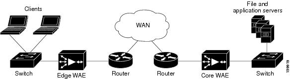
Note![]() Inline mode and WCCP redirection are exclusive. You cannot configure inline mode if the WAE is configured for WCCP operation. Inline mode is the default mode when a Cisco WAE Inline Network Adapter is installed in a WAE device, but you must configure inline mode explicitly on a device with a Cisco Interface Module.
Inline mode and WCCP redirection are exclusive. You cannot configure inline mode if the WAE is configured for WCCP operation. Inline mode is the default mode when a Cisco WAE Inline Network Adapter is installed in a WAE device, but you must configure inline mode explicitly on a device with a Cisco Interface Module.
- An inline WAE can be configured as a Central Manager, but the inline interception functionality will not be available.
- The Cisco WAE Inline Network Adapter contains two or four Ethernet ports, the Cisco Interface Module contains two to eight Ethernet ports, and the Cisco AppNav Controller Interface Module contains four to 12 Ethernet ports. Ports on the Cisco WAE Inline Network Adapter are always configured as inline ports, while ports on the Interface Modules are configured as normal standalone ports by default, and you must explicitly configure these ports as inline ports. Each pair of inline ports is grouped into a logical inline group.
- Each inline group has one LAN-facing port and one WAN-facing port. Typically, you use just one inline group, and connect the LAN-facing port to a switch and the WAN-facing port to a router. On adapters or interface modules with additional ports, additional groups of interfaces are provided if you are using a network topology where you have to connect a WAE to multiple routers. Traffic that enters into one interface in a group, exits the device via another interface in the same group.
- The following are hardware platforms supported for inline ports:
–![]() Cisco WAVE-294: Supports one installed Cisco Interface Module with 2, 4, or 8 ports.
Cisco WAVE-294: Supports one installed Cisco Interface Module with 2, 4, or 8 ports.
–![]() Cisco WAVE-594, 694, 7541, 7571, and 8541: Support one installed Cisco Interface Module with 2, 4, or 8 ports or a Cisco AppNav Controller Interface Module with 4 or 12 ports.
Cisco WAVE-594, 694, 7541, 7571, and 8541: Support one installed Cisco Interface Module with 2, 4, or 8 ports or a Cisco AppNav Controller Interface Module with 4 or 12 ports.
Note![]() The two-port 10-Gigabit Cisco Interface Module cannot be used in inline mode. The four-port 10-Gigabit Cisco AppNav Controller Interface Module is supported only on the WAVE-594.
The two-port 10-Gigabit Cisco Interface Module cannot be used in inline mode. The four-port 10-Gigabit Cisco AppNav Controller Interface Module is supported only on the WAVE-594.
- You have the option of assigning an IP address to an inline interface, but it is not required. For more information, see Configuring an IP Address on an Inline Interface.
- Traffic that flows through an inline group is transparently intercepted for optimization. Traffic that does not have to be optimized is bridged across the LAN/WAN interfaces. If a power, hardware, or unrecoverable software failure occurs, the network adapter automatically begins operating in bypass mode (fail-close), where all traffic is mechanically bridged between the LAN and WAN interfaces in each group. The Cisco WAE Inline Network Adapter and Cisco Interface Module also operate in bypass mode when the WAE is powered off or starting up. Additionally, you can manually put an inline group into bypass mode.
Note![]() AppNav Controller Interface Modules do not support automatic bypass mode to continue traffic flow in the event of a failure. For high availability, two or more AppNav Controller Interface Modules should be deployed in an AppNav cluster. For more information on using inline mode with the AppNav solution, see the chapter “Configuring Cisco AppNav”.
AppNav Controller Interface Modules do not support automatic bypass mode to continue traffic flow in the event of a failure. For high availability, two or more AppNav Controller Interface Modules should be deployed in an AppNav cluster. For more information on using inline mode with the AppNav solution, see the chapter “Configuring Cisco AppNav”.
- Inline mode is configured by default to accept all TCP traffic. If the network segment in which the WAE is inserted is carrying 802.1Q tagged (VLAN) traffic, initially, traffic on all VLANs is accepted. Inline interception can be enabled or disabled for each VLAN. However, optimization policies cannot be customized based on the VLAN.
- You can serially cluster WAE devices operating in inline mode to provide higher availability if a device fails. For details, see About Clustering Inline WAEs.
Note When a WAE inline group enters bypass mode, the switch and router ports to which it is connected may have to reinitialize, which may cause an interruption of several seconds in the traffic flow through the WAE.
If the WAE is deployed in a configuration where the creation of a loop is not possible, that is, if it is deployed in a standard fashion between a switch and a router, configure PortFast on the switch port to which the WAE is connected.
PortFast allows the port to skip the first few stages of the Spanning Tree Algorithm (STA) and move more quickly into a packet forwarding mode.
Enabling Inline Operation on WAEs
This section describes how to enable and configure inline settings on WAEs configured as application accelerators and that are not part of an AppNav Cluster (WAEs that are part of an AppNav Cluster use only the appnav-controller interception method). To configure the inline settings on WAEs configured as AppNav Controllers, see Configuring Inline Operation on ANCs.
On WAVE-294/594/694/7541/7571/8541 devices that use Cisco Interface Modules, the Interface Module ports are configured by default for normal standalone operation. If you want to use the device in inline mode, you must configure the ports for inline operation. Enabling inline mode configures all the ports for inline operation and converts each pair of ports to an inline group.
On other WAE devices that use the Cisco WAE Inline Network Adapter, the ports on the adapter always operate in inline mode. You can use this configuration window to enable or disable VLAN ID connection verification, which is the only setting that appears for such WAE devices.
To enable inline operation and configure general settings, follow these steps:
Step 1![]() From the Cisco WAAS Central Manager menu, choose Devices > device-name. (You cannot enable inline operation from device groups.)
From the Cisco WAAS Central Manager menu, choose Devices > device-name. (You cannot enable inline operation from device groups.)
Step 2![]() Choose Configure > Interception > Interception Configuration.
Choose Configure > Interception > Interception Configuration.
Note![]() If you are configuring a device using a WAAS version earlier than 5.0, choose Configure > Interception > Inline > General Settings to configure inline general settings. The configuration window looks different, but has similar settings.
If you are configuring a device using a WAAS version earlier than 5.0, choose Configure > Interception > Inline > General Settings to configure inline general settings. The configuration window looks different, but has similar settings.
The Interception Configuration window appears.
Step 3![]() From the Interception Method drop-down list, choose Inline to enable inline mode. The Interception Method drop-down list is not displayed for devices using a Cisco WAAS Version earlier than Cisco WAAS Version 5.0.
From the Interception Method drop-down list, choose Inline to enable inline mode. The Interception Method drop-down list is not displayed for devices using a Cisco WAAS Version earlier than Cisco WAAS Version 5.0.
The Interception Configuration window refreshes with the inline settings. (Figure 5-6.)
Figure 5-6 Inline Interception Settings Window
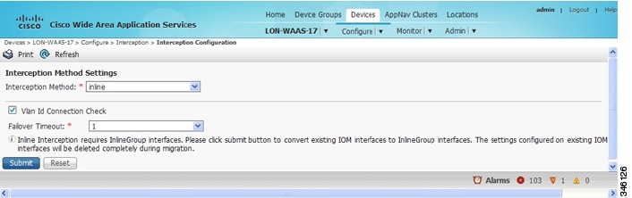
Step 4![]() Check the Inline Enable check box to enable inline operation.
Check the Inline Enable check box to enable inline operation.
The Inline Enable check box is displayed only for WAVE devices using a Cisco WAAS version earlier than Cisco WAAS Version 5.0 and that have a Cisco Interface Module installed.
Step 5![]() Check the Vlan ID Connection Check check box to enable VLAN ID connection checking. Uncheck the check box to disable it. The default setting is enabled.
Check the Vlan ID Connection Check check box to enable VLAN ID connection checking. Uncheck the check box to disable it. The default setting is enabled.
Cisco WAAS uses the VLAN ID to intercept or bridge VLAN traffic on the inline interface for a TCP flow. The VLAN ID of all the packets sent in a particular TCP connection must match; packets with a different VLAN ID will be bridged and not optimized. If your system has an asymmetric routing topology, in which the traffic flow in one direction uses a different VLAN ID than the traffic flow from the other direction, you may have to disable VLAN ID checking to ensure that the traffic is optimized.
Step 6![]() From the Failover Timeout drop-down list, choose the failover timeout (1, 5, or 25 seconds), which is the number of seconds that the interface should wait for before going into bypass mode, after a device or power failure. The default is 1 second.
From the Failover Timeout drop-down list, choose the failover timeout (1, 5, or 25 seconds), which is the number of seconds that the interface should wait for before going into bypass mode, after a device or power failure. The default is 1 second.
This item appears only for WAVE devices that use Cisco Interface Modules, but not for AppNav Controller Interface Modules. For devices that use Cisco WAE Inline Network Adapters, the failover timeout is configured in the Inline Interface Settings window (Figure 5-6). This item is named Time Out for Cisco WAAS versions earlier than Cisco WAAS Version 5.0 and appears before the VLAN ID Connection Check item.
Step 7![]() Click Submit. A message appears, for you to confirm that all the Interface Module interfaces are to be converted to inline group interfaces, and the existing Interface Module interface configurations are to be removed.
Click Submit. A message appears, for you to confirm that all the Interface Module interfaces are to be converted to inline group interfaces, and the existing Interface Module interface configurations are to be removed.
The inline groups are configured with basic default settings. To configure inline group settings, see Configuring Inline Interface Settings on WAEs.
- For devices running a Cisco WAAS Version earlier than Cisco WAAS Version 5.0, after enabling inline mode, it takes about two data feed poll cycles (about 10 minutes by default) for the inline groups to appear in the Inline Interfaces list in the lower part of the window.
- Inline mode cannot be enabled if any of the Interface Module ports are configured as the primary interface. Change the primary interface and return to this window to enable inline mode.
For devices running a Cisco WAAS version earlier than Cisco WAAS Version 5.0, if you configure any of the interfaces on an Interface Module with nondefault settings (standby group, port channel, BVI, speed, duplex, IP address, ACLs, and so on), inline mode cannot be enabled, and a warning message appears, asking you to check all the interfaces for configuration settings.
You must remove all the configuration settings from all the interface module interfaces (slot 1) and then return to this window to enable inline mode.
To enable inline operation from the CLI, use the interception-method inline global configuration command.
To configure VLAN ID checking from the CLI, use the inline vlan-id-connection-check global configuration command after inline operation is enabled.
Configuring Inline Interface Settings on WAEs
This section describes how to configure inline settings on WAEs configured as application accelerators, and that are not a part of an AppNav Cluster (WAEs that are a part of an AppNav Cluster use only the appnav-controller interception method). To configure inline settings on WAEs configured as AppNav Controllers, see Configuring Inline Operation on ANCs.
To configure inline interface settings, follow these steps:
Step 1![]() From the Cisco WAAS Central Manager menu, choose Devices > device-name. (You cannot configure inline interface settings from device groups.)
From the Cisco WAAS Central Manager menu, choose Devices > device-name. (You cannot configure inline interface settings from device groups.)
Step 2![]() Choose Configure > Interception > Interception Configuration.
Choose Configure > Interception > Interception Configuration.
Note![]() If you are configuring a device using a Cisco WAAS version earlier than Cisco WAAS Version 5.0, choose Configure > Interception > Inline > Inline Interfaces to configure inline interface settings. The configuration window looks different, but has similar settings.
If you are configuring a device using a Cisco WAAS version earlier than Cisco WAAS Version 5.0, choose Configure > Interception > Inline > Inline Interfaces to configure inline interface settings. The configuration window looks different, but has similar settings.
The Inline Interfaces window appears, listing the inline interface groups available on the device.
Step 3![]() Choose an inline group to configure and click the Edit taskbar icon. (For devices using a Cisco WAAS version earlier than Cisco WAAS Version 5.0, click the Edit icon next to the interface.)
Choose an inline group to configure and click the Edit taskbar icon. (For devices using a Cisco WAAS version earlier than Cisco WAAS Version 5.0, click the Edit icon next to the interface.)
The Edit Inline Settings window appears, displaying the inline interface configurations for a particular slot and port group (Figure 5-7).
Figure 5-7 Edit Inline Settings Window
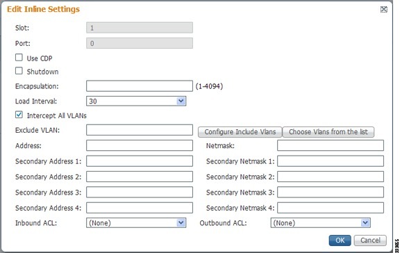
Step 4![]() Check the Use CDP check box to enable Cisco Discovery Protocol (CDP) on the inline group interfaces. The Use CDP check box is not shown for devices using a Cisco WAAS version earlier than Cisco WAAS Version earlier than 5.0.
Check the Use CDP check box to enable Cisco Discovery Protocol (CDP) on the inline group interfaces. The Use CDP check box is not shown for devices using a Cisco WAAS version earlier than Cisco WAAS Version earlier than 5.0.
When enabled, CDP obtains protocol addresses of neighboring devices and discovers the platform of those devices. It also shows information about the interfaces used by your router.
Configuring CDP from the CDP Settings window enables CDP globally on all the interfaces. For information on configuring CDP settings, see Configuring CDP Settings in the chapter “Configuring Network Settings” .
Step 5![]() Check the Shutdown check box to shut down the inline group. This setting bridges traffic across the LAN/WAN interfaces without any processing.
Check the Shutdown check box to shut down the inline group. This setting bridges traffic across the LAN/WAN interfaces without any processing.
Step 6![]() In the Encapsulation field, enter the VLAN ID that is to be assigned to traffic that leaves the WAE. The VLAN ID should be set to match the VLAN ID expected by the router.
In the Encapsulation field, enter the VLAN ID that is to be assigned to traffic that leaves the WAE. The VLAN ID should be set to match the VLAN ID expected by the router.
For more information about the VLAN ID, see Configuring an IP Address on an Inline Interface.
Step 7![]() From the Load Interval drop-down list, choose the interval, in seconds, at which to poll the interface for statistics and calculate throughput. The default is 30 seconds. (The Load Interval item is not shown for devices using a Cisco WAAS version earlier than Cisco WAAS Version 5.0.)
From the Load Interval drop-down list, choose the interval, in seconds, at which to poll the interface for statistics and calculate throughput. The default is 30 seconds. (The Load Interval item is not shown for devices using a Cisco WAAS version earlier than Cisco WAAS Version 5.0.)
Step 8![]() Check the Intercept all VLANs check box to enable inline interception on the interface group. Inline interception is enabled by default when the WAE contains a Cisco WAE Inline Network Adapter, but must be explicitly enabled on devices with a Cisco Interface Module (see Enabling Inline Operation on WAEs).
Check the Intercept all VLANs check box to enable inline interception on the interface group. Inline interception is enabled by default when the WAE contains a Cisco WAE Inline Network Adapter, but must be explicitly enabled on devices with a Cisco Interface Module (see Enabling Inline Operation on WAEs).
Step 9![]() In the Exclude VLAN field, enter a list of one or more VLAN ranges to exclude from optimization. You can enter the word native to exclude the native VLAN. Separate each VLAN range from the next with a comma. Alternatively, you can select VLAN ranges from a list by following these steps:
In the Exclude VLAN field, enter a list of one or more VLAN ranges to exclude from optimization. You can enter the word native to exclude the native VLAN. Separate each VLAN range from the next with a comma. Alternatively, you can select VLAN ranges from a list by following these steps:
a.![]() Click Configure Include VLANs when you know the list of VLANs that you want to include in inline interception. This button runs a script that prompts you for a comma-separated list of VLANs that you want to include. The script generates an inverse list of all the VLANs that should be excluded and then updates the window and puts the list into the Exclude VLAN field.
Click Configure Include VLANs when you know the list of VLANs that you want to include in inline interception. This button runs a script that prompts you for a comma-separated list of VLANs that you want to include. The script generates an inverse list of all the VLANs that should be excluded and then updates the window and puts the list into the Exclude VLAN field.
b.![]() Click Choose VLANs from the list to choose VLAN ranges. The VLAN Range Assignments window appears, displaying the VLAN ranges that are defined. Defining VLAN ranges is described in Configuring VLANs for Inline Support.
Click Choose VLANs from the list to choose VLAN ranges. The VLAN Range Assignments window appears, displaying the VLAN ranges that are defined. Defining VLAN ranges is described in Configuring VLANs for Inline Support.
c.![]() Choose the VLAN ranges to include or exclude:
Choose the VLAN ranges to include or exclude:
–![]() Check the check box next to each VLAN range that you want to include for optimization, and click the Include Vlan taskbar icon. All the VLANs that are not included for optimization are excluded. For devices using a Cisco WAAS version earlier than Cisco WAAS Version 5.0, click
Check the check box next to each VLAN range that you want to include for optimization, and click the Include Vlan taskbar icon. All the VLANs that are not included for optimization are excluded. For devices using a Cisco WAAS version earlier than Cisco WAAS Version 5.0, click  next to each VLAN range that you want to include. The icon changes to
  .
.
–![]() Check the check box next to each VLAN range that you want to exclude from optimization, and click the Exclude Vlan taskbar icon. For devices using a Cisco WAAS version earlier than Cisco WAAS Version 5.0, click
Check the check box next to each VLAN range that you want to exclude from optimization, and click the Exclude Vlan taskbar icon. For devices using a Cisco WAAS version earlier than Cisco WAAS Version 5.0, click  next to each VLAN range that you want to exclude from optimization. The icon changes to
  .
.
–![]() Click the Clear Selection taskbar icon to clear all selections. For devices using a Cisco WAAS version earlier than Cisco WAAS Version 5.0, click
Click the Clear Selection taskbar icon to clear all selections. For devices using a Cisco WAAS version earlier than Cisco WAAS Version 5.0, click  in the taskbar to select all the available VLAN ranges for optimization, or click
  in the taskbar to exclude all the VLAN ranges from optimization.
d.![]() Click OK. For devices using a Cisco WAAS version earlier than Cisco WAAS Version 5.0, click Submit.
Click OK. For devices using a Cisco WAAS version earlier than Cisco WAAS Version 5.0, click Submit.
Step 10![]() From the Failover Timeout drop-down list, choose 1 second (default), 3 seconds, 5 seconds, or 10 seconds. This value sets the number of seconds after a failure event that the Cisco WAE waits for before beginning to operate in bypass mode. In bypass mode, all the traffic received on either port of the interface group is forwarded out to the other port in the group.
From the Failover Timeout drop-down list, choose 1 second (default), 3 seconds, 5 seconds, or 10 seconds. This value sets the number of seconds after a failure event that the Cisco WAE waits for before beginning to operate in bypass mode. In bypass mode, all the traffic received on either port of the interface group is forwarded out to the other port in the group.
This check box applies only to devices that use Cisco WAE Inline Network Adapters. For devices that use Cisco Interface Modules, the failover timeout is configured in the Inline Interception Settings window (Figure 5-6) and does not appear in this window.
Step 11![]() Configure the Speed and Mode port settings as follows (these settings are not used for the interfaces on the Cisco Interface Module on a device using Cisco WAAS Version 5.0 or later, which uses auto sensing):
Configure the Speed and Mode port settings as follows (these settings are not used for the interfaces on the Cisco Interface Module on a device using Cisco WAAS Version 5.0 or later, which uses auto sensing):
a.![]() Uncheck the AutoSense check box, which is enabled by default.
Uncheck the AutoSense check box, which is enabled by default.
b.![]() From the Speed drop-down list, choose a transmission speed (10, 100, 1000, or 10000 Mbps). Choose 1000 Mbps for fiber Gigabit Ethernet interfaces on a Cisco Interface Module for devices using a Cisco WAAS version earlier than Cisco WAAS Version 5.0.
From the Speed drop-down list, choose a transmission speed (10, 100, 1000, or 10000 Mbps). Choose 1000 Mbps for fiber Gigabit Ethernet interfaces on a Cisco Interface Module for devices using a Cisco WAAS version earlier than Cisco WAAS Version 5.0.
c.![]() From the Mode drop-down list, choose a transmission mode (full-duplex or half-duplex). Choose full-duplex for fiber Gigabit Ethernet interfaces on a Cisco Interface Module for devices using a Cisco WAAS version earlier than Cisco WAAS Version 5.0.
From the Mode drop-down list, choose a transmission mode (full-duplex or half-duplex). Choose full-duplex for fiber Gigabit Ethernet interfaces on a Cisco Interface Module for devices using a Cisco WAAS version earlier than Cisco WAAS Version 5.0.
Note![]() We strongly recommend that you do not use half-duplex connections on WAEs or on routers, switches, or other devices. Half duplex impedes performance and should not be used. Check each Cisco WAE interface and port configuration on the adjacent device (router, switch, firewall, and WAE) to verify that full duplex is configured.
We strongly recommend that you do not use half-duplex connections on WAEs or on routers, switches, or other devices. Half duplex impedes performance and should not be used. Check each Cisco WAE interface and port configuration on the adjacent device (router, switch, firewall, and WAE) to verify that full duplex is configured.
Step 12![]() In the Address field, enter an IP address for the inline interface, if you want to assign an IP address.
In the Address field, enter an IP address for the inline interface, if you want to assign an IP address.
Step 13![]() In the Netmask field, enter a subnet mask for the inline interface.
In the Netmask field, enter a subnet mask for the inline interface.
Step 14![]() Enter up to four secondary IP addresses and corresponding subnet masks in the Secondary Address and Secondary Netmask fields.
Enter up to four secondary IP addresses and corresponding subnet masks in the Secondary Address and Secondary Netmask fields.
Configuring multiple IP addresses allows the device to be present in more than one subnet and can be used to optimize response time because it allows the data to go directly from the Cisco WAAS device to the client that is requesting the information without being redirected through a router. The Cisco WAAS device becomes visible to the client because both are configured on the same subnet.
Step 15![]() In the Default Gateway field, enter the default gateway IP address. The Default Gateway field is not shown for devices using a Cisco WAAS version earlier than Cisco WAAS Version 5.0 or later.
In the Default Gateway field, enter the default gateway IP address. The Default Gateway field is not shown for devices using a Cisco WAAS version earlier than Cisco WAAS Version 5.0 or later.
Step 16![]() (Optional) From the Inbound ACL drop-down list, choose an IP ACL to apply to inbound packets.
(Optional) From the Inbound ACL drop-down list, choose an IP ACL to apply to inbound packets.
The drop-down list contains all the IP ACLs that you configured in the system.
Step 17![]() (Optional) From the Outbound ACL drop-down list, choose an IP ACL to apply to outbound packets.
(Optional) From the Outbound ACL drop-down list, choose an IP ACL to apply to outbound packets.
Step 18![]() Under IPv6 Settings, you can manually assign an IPv6 address to the inline interface or select from the following options. If you select one of the following options, the IPv6 address field and subsequent secondary IPv6 address fields are not available.
Under IPv6 Settings, you can manually assign an IPv6 address to the inline interface or select from the following options. If you select one of the following options, the IPv6 address field and subsequent secondary IPv6 address fields are not available.
- Use Single Link Local: A unicast address that is automatically configured on an interface using the link-local prefix FE80::/10 and the interface identifier in the modified EUI-64 format. Using this address configuration option is sufficient for nodes on a link to communicate.
- Use Auto Config: To autoconfigure an IPv6 global unicast address on the interface as per RFC 4862.
Step 19![]() Enter up to four secondary IP addresses and corresponding subnet masks in the Secondary Address and Secondary Netmask fields
Enter up to four secondary IP addresses and corresponding subnet masks in the Secondary Address and Secondary Netmask fields
Configuring multiple IP addresses allows the device to be present in more than one subnet and can be used to optimize response time because it allows the data to go directly from the Cisco WAAS device to the client that is requesting the information without being redirected through a router. The Cisco WAAS device becomes visible to the client because both are configured on the same subnet.
Step 20![]() In the Duplicate Address Detection Attempts field enter a number between 0-600 to specify the number of attempts by which the duplicate address should be detected.
In the Duplicate Address Detection Attempts field enter a number between 0-600 to specify the number of attempts by which the duplicate address should be detected.
For devices using a Cisco WAAS version earlier than Cisco WAAS Version 5.0, click Submit.
Step 22![]() For Cisco WAAS Version 5.0 and later, choose Configure > Network > Default Gateway to configure the default gateway for an inline interface:
For Cisco WAAS Version 5.0 and later, choose Configure > Network > Default Gateway to configure the default gateway for an inline interface:
a.![]() In the Default Gateway field, enter the default gateway IP address.
In the Default Gateway field, enter the default gateway IP address.
To configure inline interception from the Cisco WAAS CLI, use the interface InlineGroup global configuration command.
Configuring Inline Operation on ANCs
This section describes how to enable and configure inline settings on Cisco WAAS devices configured as AppNav Controllers (ANCs). You can also use the AppNav Cluster wizard to configure an inline ANC and create an inline bridge interface, as described in Creating a New AppNav Cluster with the AppNav Cluster Wizard in the chapter “Configuring Cisco AppNav” .
To configure the inline settings on WAEs configured as application accelerators, see Enabling Inline Operation on WAEs.
On WAVE-594, 694, 7541, 7571, and 8541 devices that use Cisco AppNav Controller Interface Modules, the AppNav Controller Interface Module ports are configured by default for normal standalone operation. To use the device in Inline mode, you must configure the ports for inline operation and create an inline bridge group. Enabling Inline mode configures all the ports for inline operation.
To enable inline operation and configure an Inline Bridge Group, follow these steps:
Step 1![]() From the Cisco WAAS Central Manager menu, choose Devices > device-name. (You cannot enable inline operation from device groups.)
From the Cisco WAAS Central Manager menu, choose Devices > device-name. (You cannot enable inline operation from device groups.)
Step 2![]() Choose Configure > Interception > Interception Configuration.
Choose Configure > Interception > Interception Configuration.
The Interception Configuration window appears.
Step 3![]() From the Interception Method drop-down list, choose Inline to enable inline mode.
From the Interception Method drop-down list, choose Inline to enable inline mode.
Step 4![]() Click Submit to enable inline mode and refresh the window with additional settings.
Click Submit to enable inline mode and refresh the window with additional settings.
All the existing bridge groups are listed, showing the bridge group number, protocol, link state propagation setting, VLAN ranges, and included interfaces.
From this list, you can perform the following tasks:
Step 5![]() Click the Create Bridge taskbar icon.
Click the Create Bridge taskbar icon.
Figure 5-8 Create Bridge window
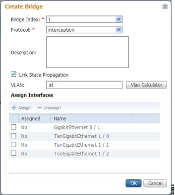
Step 6![]() From the Bridge Index drop-down list, choose the bridge group number.
From the Bridge Index drop-down list, choose the bridge group number.
Step 7![]() (Optional) In the Description field, enter a bridge group description.
(Optional) In the Description field, enter a bridge group description.
Step 8![]() (Optional) Check the Link State Propagation check box to enable link state propagation. It is enabled by default.
(Optional) Check the Link State Propagation check box to enable link state propagation. It is enabled by default.
Link state propagation means that if one interface in the inline bridge group is down, the system automatically shuts down the other interface to ensure that a network failover scheme is triggered.
Step 9![]() (Optional) Configure VLANs to include in interception. Initially, all the VLANS are included. To include or exclude specific VLAN ranges, follow these steps:
(Optional) Configure VLANs to include in interception. Initially, all the VLANS are included. To include or exclude specific VLAN ranges, follow these steps:
b.![]() For each VLAN range that you want to include in interception, choose Add/Include from the Select Operation Type drop-down list. In the Vlan Range field, enter a comma-separated list of one or more VLAN ranges to include. You can enter the word native to include the native VLAN.
For each VLAN range that you want to include in interception, choose Add/Include from the Select Operation Type drop-down list. In the Vlan Range field, enter a comma-separated list of one or more VLAN ranges to include. You can enter the word native to include the native VLAN.
c.![]() For each VLAN range that you want to exclude from interception, choose Except/Exclude from the Select Operation Type drop-down list. In the Vlan Range field, enter a comma-separated list of one or more VLAN ranges to exclude. You can enter the word native to exclude the native VLAN.
For each VLAN range that you want to exclude from interception, choose Except/Exclude from the Select Operation Type drop-down list. In the Vlan Range field, enter a comma-separated list of one or more VLAN ranges to exclude. You can enter the word native to exclude the native VLAN.
d.![]() Click OK to save your settings.
Click OK to save your settings.
Step 10![]() In the Assign Interfaces area, check the check box next to two interfaces that you want to assign to this bridge group, and then click the Assign taskbar icon. To unassign assigned interfaces, check each interface that you want to unassign, and click the Unassign taskbar icon. The bridge group can contain two physical or two port-channel interfaces, or a combination.
In the Assign Interfaces area, check the check box next to two interfaces that you want to assign to this bridge group, and then click the Assign taskbar icon. To unassign assigned interfaces, check each interface that you want to unassign, and click the Unassign taskbar icon. The bridge group can contain two physical or two port-channel interfaces, or a combination.
Step 11![]() Click OK to create the bridge group.
Click OK to create the bridge group.
Configuring an IP Address on an Inline Interface
You can assign IP addresses to the inline group interfaces, but it is not required. You can assign a primary IP address and up to four secondary IP addresses, using the procedure described in Configuring Inline Interface Settings on WAEs.
You can set an inline group interface as the primary interface on the WAE by using the Configure > Network > Network Interfaces window, in the Primary Interface drop-down list.
In scenarios where the primary interface for a WAE is set to an inline group interface and management traffic is configured on a separate IP address (either on a secondary IP address on the same inline group interface or on a built-in interface), configure the Cisco WAAS Central Manager to communicate with the WAE on the IP address designated for management traffic. Configure the WAE management interface settings with the Configure > Network > Management Interface Settings menu item. For a Cisco WAAS version earlier than Cisco WAAS Version 5.0, configure the WAE management traffic IP address in the device-name > Activation window, in the Management IP field.
If a WAE operating in inline mode is present in an 802.1Q VLAN trunk line between a switch and a router, and you are configuring the inline interface with an IP address, you must set the VLAN ID that is to be assigned to the traffic that leaves the WAE. The VLAN ID should be set to match the VLAN ID expected by the router.
Use the encapsulation dot1Q interface command to assign a VLAN ID, as follows:
This example shows how to assign VLAN ID 100 to the traffic leaving the WAE. The VLAN ID can range from 1 to 4094.
Note You can set the VLAN ID of the inline traffic by using the encapsulation dot1Q interface command or by using the Central Manager menu item Configure > Interception > Interception Configuration (see Configuring Inline Interface Settings on WAEs).
If the VLAN ID that you set does not match the VLAN ID expected by the router subinterface, you may not be able to connect to the inline interface IP address.
The inline adapter supports only a single VLAN ID for each inline group interface. If you have configured a secondary address from a different subnet on an inline interface, you must have the same secondary address assigned on the router subinterface for the VLAN.
Using IEEE 802.1Q tunneling increases the frame size by 4 bytes when the tag is added. Therefore, you must configure all the switches through which the tunneled packet traverses to be able to process larger frames by increasing the device MTU to at least 1504 bytes.
Note![]() When an Inline interface on a WAE configured with IPv6 address and dot1 q encapsulation, tries to communicate with an IPv6 default gateway, the communication fails. If the same device, configured with IPv4 address and dot1 Q encapsulation, tries to communicate with an IPv4 default gateway, the communication is successful.
When an Inline interface on a WAE configured with IPv6 address and dot1 q encapsulation, tries to communicate with an IPv6 default gateway, the communication fails. If the same device, configured with IPv4 address and dot1 Q encapsulation, tries to communicate with an IPv4 default gateway, the communication is successful.
Note that when dot1Q encapsulation is disabled, the WAE (configured with either IPv6 or IPv4) can successfully reach the default gateway of the relevant IP type.
The following operating considerations apply to configuring IP addresses on the inline interfaces:
- This feature provides basic routable interface support and does not support the following additional features associated with the built-in interfaces: standby and port channel.
- If you have configured a WAE to use inline interfaces for all traffic, inline interception must be enabled; otherwise, the WAE will not receive any traffic.
- If you have configured a WAE to use the inline interfaces for all traffic, and it goes into mechanical bypass mode, the WAE become inaccessible through the inline interface IP address. Console access is required for device management when an inline interface is in bypass mode.
- If you have configured a WAE with an IP address on an inline interface, the interface can accept only traffic addressed to it and ARP broadcasts, and the interface cannot accept multicast traffic.
- In a deployment using the Hot Standby Router Protocol (HSRP) where two routers that participate in an HSRP group are directly connected through two inline groups, HSRP works for all the clients if the active router fails. However, this redundancy does not apply to the IP address of the WAE itself for management traffic, if management traffic is also configured to use the inline interface. If the active router fails, you will not be able to connect to the WAE inline IP address because the inline interface is physically connected to the failed router interface. You will be able to connect to the WAE through the second inline group interface that is connected to the standby router. If redundancy is needed for the IP address of the WAE itself for management traffic, we recommend that you use the IP addresses of the built-in interfaces rather than the inline interfaces.
Configuring VLANs for Inline Support
Initially, the WAE accepts traffic from all VLANs. You can configure the WAE to include or exclude traffic from certain VLANs; for excluded VLANs, traffic is bridged across the LAN/WAN interfaces in a group and is not processed.
To configure a VLAN for inline support, follow these steps:
Step 1![]() From the Cisco WAAS Central Manager menu, choose Configure > Platform > Vlans.
From the Cisco WAAS Central Manager menu, choose Configure > Platform > Vlans.
The VLANs window appears, which lists the VLANs that are defined. From this list, you can perform the following tasks:
Step 2![]() Click the Add VLAN taskbar icon. The VLAN pane appears.
Click the Add VLAN taskbar icon. The VLAN pane appears.
Step 3![]() In the Name field, enter a name for the VLAN list.
In the Name field, enter a name for the VLAN list.
Step 4![]() In the Ranges field, enter a list of one or more VLAN ranges. Separate each VLAN range from the next with a comma (but no space). This list of VLAN ranges can be included or excluded from optimization when you configure the inline interface group, as described in Configuring Inline Interface Settings on WAEs. You cannot specify the term native in this field.
In the Ranges field, enter a list of one or more VLAN ranges. Separate each VLAN range from the next with a comma (but no space). This list of VLAN ranges can be included or excluded from optimization when you configure the inline interface group, as described in Configuring Inline Interface Settings on WAEs. You cannot specify the term native in this field.
This facility for creating VLAN lists is provided so that you can configure VLAN lists globally. You do not have to use this facility to configure VLANs for an inline interface. You can configure VLANs directly in the inline interface settings window, as described in Configuring Inline Interface Settings on WAEs.
About Clustering Inline WAEs
You can serially cluster two WAE devices that are operating in inline mode to provide higher availability in the data center if a device fails.
Consider the following operating guidelines for clustering inline WAE devices:
- If the current optimizing device fails, the inline group shuts down, or the device becomes overloaded, the second WAE device in the cluster provides the optimization services. Deploying WAE devices in a serial inline cluster for scaling or load balancing is not supported.
Note![]() Overload failover occurs on TFO overload, not overload of individual application accelerators, and it is intended for temporary overload protection. We do not recommend that you continually run a WAE in an overloaded state, frequently triggering overload failover.
Overload failover occurs on TFO overload, not overload of individual application accelerators, and it is intended for temporary overload protection. We do not recommend that you continually run a WAE in an overloaded state, frequently triggering overload failover.
- A serial cluster consists of two WAE devices connected together sequentially in the traffic path. The WAN port of one device is connected to the LAN port of the next device, as shown in Figure 5-9.
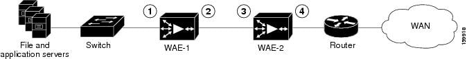
|
|
|
||
|
|
|
- In a serial cluster, all the traffic between a switch and router passes through all the inline WAEs. In Figure 5-9, TCP connections are optimized by WAE-1. If WAE-1 fails, it bypasses the traffic and connections are then optimized by WAE-2.
- The policy configuration of serially clustered WAEs should be the same. Additionally, we recommend that you use the same device for both the WAEs in the cluster.
- When serially clustering inline WAEs, on each WAE, you must configure the address of the other WAE in the cluster as a nonoptimizing peer. This disables optimization between the two peer WAEs in the serial cluster, since you want optimization only between the WAE peers on each side of the WAN link. For information on how to disable optimization between peers, see Disabling Peer Optimization Between Serial Inline WAEs.
Disabling Peer Optimization Between Serial Inline WAEs
To disable peer optimization between WAEs in a serial cluster, follow these steps:
Step 1![]() From the Cisco WAAS Central Manager menu, choose Devices > device-name. (You cannot configure peer settings from device groups.)
From the Cisco WAAS Central Manager menu, choose Devices > device-name. (You cannot configure peer settings from device groups.)
Step 2![]() Choose Configure > Peers > Peer Settings.
Choose Configure > Peers > Peer Settings.
The Peer Settings window appears (Figure 5-10).
Figure 5-10 Peer Settings Window
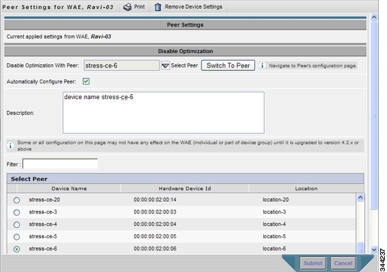
Step 3![]() Click the Select Peer triangle control to display the other WAEs that are registered with this Central Manager, in the lower part of the window (see the Select Peer area).
Click the Select Peer triangle control to display the other WAEs that are registered with this Central Manager, in the lower part of the window (see the Select Peer area).
Step 4![]() In the Select Peer area, click the radio button next to the serial peer of the current device. The peer device name appears in the Disable Optimization With Peer field.
In the Select Peer area, click the radio button next to the serial peer of the current device. The peer device name appears in the Disable Optimization With Peer field.
To filter the device list, enter a string in the Filter field. As you enter characters, the device list is dynamically filtered to include only devices that have the filter string in their name or hardware device ID.
Step 5![]() Check the Automatically Configure Peer check box to allow the Cisco WAAS Central Manager to configure the other peer with a similar setting to disable optimization with the current device.
Check the Automatically Configure Peer check box to allow the Cisco WAAS Central Manager to configure the other peer with a similar setting to disable optimization with the current device.
If you do not check this check box, you must manually configure the other peer to disable optimization with the current device. After you submit your changes, you can click Switch to Peer to go to this same configuration page for the peer device.
Step 6![]() In the Description field, enter a description for the peer. The default description is the device name of the peer.
In the Description field, enter a description for the peer. The default description is the device name of the peer.
To disable serial peer optimization from the CLI, use the no peer device-id global configuration command. To re-enable serial peer optimization, use the peer device-id global configuration command.
To view the status of all the serial cluster pairs registered with the Cisco WAAS Central Manager, from the Cisco WAAS Central Manager menu, choose Configure > Global > Peer Settings. The Peer Settings status window appears, as shown in Figure 5-11.
Figure 5-11 Peer Settings For All Devices Window
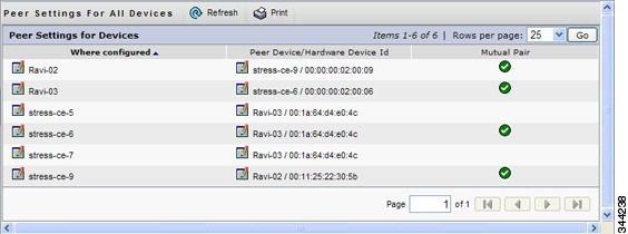
The window lists each WAE for which you have configured peer optimization settings. Verify that there are two entries for each serial cluster pair, both with a check mark in the Mutual Pair column. There should be an entry for each WAE in the pair, for example, the first and last entries in the figure.
If you see an entry without a check mark in the Mutual Pair column (like the third one in the figure), it indicates a WAE on which a serial peer is configured, but the peer is not similarly configured with the first device as its serial peer.Configuring Cisco AppNav Interception
For WAEs that are a part of an AppNav deployment and are configured as Cisco WAAS nodes in an AppNav Cluster, you must configure them to use the appnav-controller interception method. These WAAS nodes receive traffic only from the ANCs, not directly from routers. It is on the ANC devices that you configure an interception method, such as WCCP, PBR, or inline to intercept network traffic. For more information about an AppNav deployment, see the chapter “Configuring Cisco AppNav” .
Note![]() ISR-WAAS devices support only the AppNav Controller interception method.
ISR-WAAS devices support only the AppNav Controller interception method.
If you create an AppNav Cluster by using the Cisco WAAS Central Manager wizard, or you add WAAS nodes to a cluster through the AppNav Clusters window, the Cisco WAAS Central Manager automatically configures WAAS nodes with the appnav-controller interception method. After the WAAS node is added to a cluster, its interception method cannot be changed.
To manually configure appnav-controller interception on a WAAS node, follow these steps:
Step 1![]() From the Cisco WAAS Central Manager menu, choose Devices > device-name.
From the Cisco WAAS Central Manager menu, choose Devices > device-name.
Step 2![]() Choose Configure > Interception > Interception Configuration. The Interception Configuration window appears.
Choose Configure > Interception > Interception Configuration. The Interception Configuration window appears.
Step 3![]() From the Interception Method drop-down list, choose appnav-controller to enable the appnav-controller interception method.
From the Interception Method drop-down list, choose appnav-controller to enable the appnav-controller interception method.
 Feedback