Licensing Requirements
For a complete explanation of Cisco NX-OS licensing recommendations and how to obtain and apply licenses, see the Cisco NX-OS Licensing Guide.
The documentation set for this product strives to use bias-free language. For the purposes of this documentation set, bias-free is defined as language that does not imply discrimination based on age, disability, gender, racial identity, ethnic identity, sexual orientation, socioeconomic status, and intersectionality. Exceptions may be present in the documentation due to language that is hardcoded in the user interfaces of the product software, language used based on RFP documentation, or language that is used by a referenced third-party product. Learn more about how Cisco is using Inclusive Language.
This chapter describes how to configure Catena on a Cisco NX-OS device.
This chapter includes the following sections:
For a complete explanation of Cisco NX-OS licensing recommendations and how to obtain and apply licenses, see the Cisco NX-OS Licensing Guide.
Catena provides hardware (TCAM) based application chaining solution for Cisco Nexus devices so that packets can be redirected through multiple physical or virtual devices without changing the topology or the existing configuration. The solution works with all L4-L7 virtual and physical devices, such as firewalls, IPS, IDS, DoS Protection, WAAS, SSL offload engines, networking monitoring devices, switches, virtual appliances, and containers.
Catena allows you to create several chains with multiple elements in each chain. You can configure security policies to specify segments of traffic through a particular chain. For example, an element could be a cluster of devices, in which case, catena load-balances to the cluster. Catena performs health monitoring and failure handling of devices.
Some of the key features of Catena are as follows:
 Note |
Catena supports IPv4 and IPv6 addresses. |
Increases wire-speed performance.
Adds zero-latency to traffic.
Catena supports full ACL, including source IP, destination IP, source Layer 4 port number and destination Layer 4 port number.
Allows you to insert additional appliances with minimal configuration changes to existing device architecture, and so not require complex changes to the wiring.
Deploys appliances with zero-touch feature. Catena does not need special header or data path packet modification that is compatible with your existing hardware and software. As a result any appliance works without any special certification or support from the vendor.
Provides selective traffic chaining using ACLs. For example, any traffic entering at the ingress port is matched against your ACL. If the traffic matches your ACL it is ingested into the traffic chain.
Redirects line-rate traffic to multiple appliances.
Monitors health of the devices using PING (ICMP), TCP, HTTP, UDP, or DNS probes. Catena sends periodic probe packets to all the appliances. When an appliance responds in a healthy manner within a specified time, it is used to load balance traffic. Catena also handles automatic failure. Note that at the time of failure, you do not need to intervene.
Catena offers a range of features for chaining devices without affecting the existing topology or configuration. Catena provides you the following benefits:
Segmentation of traffic.
CAPEX savings.
OPEX savings: without catena, you need to perform VLAN stitching or create a default gateway, which is hard to deploy and hard to add or remove devices.
Provides Telemetry and analytics.
Without catena, either all traffic is in a chain or not in a chain. Catena allows secure traffic partitioning through multiple chains. Without catena, you cannot create multiple chains using the same network elements.
Catena is also a platform, for which users can write applications.
Catena has the following guidelines and limitations:
Catena is supported for the Cisco Nexus 9200, 9300, and 9300-EX Series switches.
Note |
We recommend that you allocate sufficient TCAM space to PACL and VACL for Catena Transparent Mode (PACL, VACL), and for Catena Routed Mode. |
When configuring a catena instance in routed mode, you must enable PBR and IP SLA features.
Catena supports full ACL, including source IP, Destination IP, Source L4 port number and Destination L4 port number
Does not support IPv6 probes in catena chains.
Supports only one instance per port or VLAN groups.
You must shut down a catena instance before making changes to either VLAN, port, or device groups.
You can create multiple chains, each comprising multiple functions and services; configure each chain to run on multiple devices; and apply network policies to these elements. You can create chains using the following deployment modes:
Transparent mode
Routed mode
Mixed mode, including both Transparent and Routed mode in the same chain
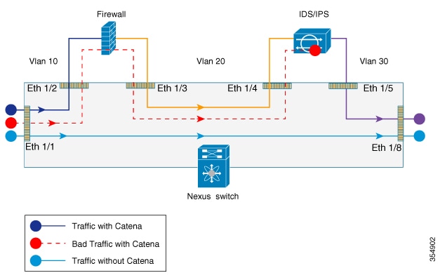
The following figure shows the traffic flow between appliances in the transparent mode when catena is enabled, enabled with bad traffic, and disabled.
The following figure shows how Catena uses a cross function of IP-ACL entries along with TCAM FIB to bucket the traffic streams to multiple egress interfaces.
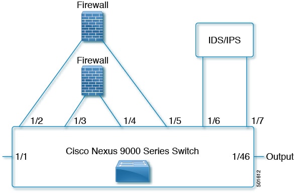
Catena uses source IP or destination IP to determine the egress interface. Egress interface ports are bundled using the link aggregation control protocol (LACP), and hash algorithms are used for symmetric load balancing.
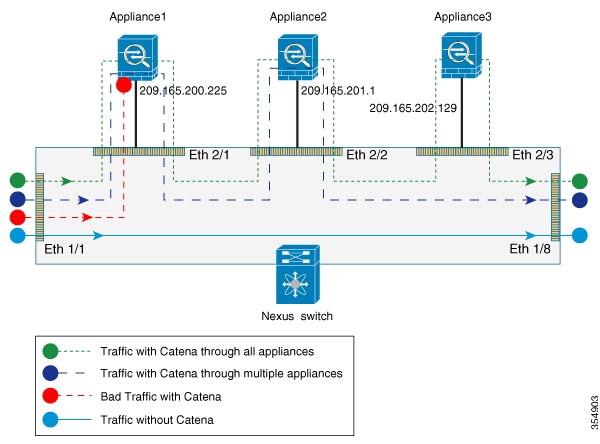
The following figure shows the traffic flow between appliances in the routed mode when catena is enabled, enabled with bad traffic, and disabled.
You can configure catena service in the default VRF or in non-default VRFs.
For the catena service to successfully redirect traffic, all the ingress interfaces and device-group nodes must belong to the same VRF. You must ensure that all ingress interfaces and node members within the associated device group are reachable in the configured VRF.
You can configure Cisco Nexus devices such that packets can be redirected through multiple devices using Catena.
To configure catena:
Enable catena.
Create a port group.
Create a VLAN group.
Create a device group.
Create an IP ACL.
Create a Port ACL.
Create a catena instance.
By default, catena is disabled on the Cisco NX-OS device. You must explicitly enable catena to configure and verify authentication commands.
Ensure that you have installed the network services license. When configuring a catena instance in routed mode, you must enable PBR and IP SLA features.
| Command or Action | Purpose | |||
|---|---|---|---|---|
| Step 1 |
configure terminal Example: |
Enters global configuration mode. |
||
| Step 2 |
[no] feature catena enabling or disabling Example: |
Enables catena. Use the no form of this command to disable catena.
|
||
| Step 3 |
(Optional) copy running-config startup-config Example: |
(Optional)
Copies the running configuration to the start up configuration. |
A port group consists of a set of interfaces. You must configure port groups for both routed and transparent modes.
Note |
If the egress port has multiple ports, then traffic is load balanced. |
| Command or Action | Purpose | |
|---|---|---|
| Step 1 |
configure terminal Example: |
Enters global configuration mode. |
| Step 2 |
catena port-group port-group-name Example: |
Creates a catena port group, and enters port group configuration mode. |
| Step 3 |
interface interface-reference Example: |
Configures active catena ports, with link-based tracking enabled by default. |
| Step 4 |
(Optional) copy running-config startup-config Example: |
(Optional)
Copies the running configuration to the startup configuration. |
To create and configure a VLAN group:
| Command or Action | Purpose | |
|---|---|---|
| Step 1 |
configure terminal Example: |
Enters global configuration mode. |
| Step 2 |
catena vlan-group vlan-group-name Example: |
Creates a catena VLAN group, and enters VLAN configuration mode. |
| Step 3 |
vlan vlan-range Example: |
Assign a VLAN to the configured VLAN group. Repeat this step to specify all VLANs. |
| Step 4 |
(Optional) copy running-config startup-config Example: |
(Optional)
Copies the running configuration to the startup configuration. |
A device group contains a list of node IP addresses. If you are creating a Layer 3 routed mode deployment, you must create a device group.
To create and configure a device group:
Note |
If there are multiple nodes, then traffic is load balanced accordingly. |
| Command or Action | Purpose | |
|---|---|---|
| Step 1 |
configure terminal Example: |
Enters global configuration mode. |
| Step 2 |
catena device-group device-group-name Example: |
Creates a device group and enters the device group configuration mode. |
| Step 3 |
node {ip ipv4-address | IPv6 ipv6-address } Example:Example: |
Configures a list of node IP addresses. These are the IP addresses of your appliances. Traffic is redirected to the appliances that can perform load balancing. These devices must be in active mode. In the example, node ip 1.1.1.1, node ip 2.2.2.2, and node ip 3.3.3.3 are the IP addresses of the appliances. |
| Step 4 |
probe probe-id [control status] [host host-name] [frequency frequency-number | timeout timeout | retry-down-count down-count | retry-up-count up-count | ip ipv4-address] Example: |
Configure the device group probe. You can specify an Internet Control Message Protocol (ICMP), Transmission Control Protocol (TCP), Hypertext Transfer Protocol (HTTP), User Datagram Protocol (UDP), or Domain Name System (DNS) probe for the catena instance. The following describe some of the keyword-argument pairs:
|
| Step 5 |
(Optional) vrf vrf-name Example: |
(Optional)
Configures VRF for a device group. |
You will need to determine the type of traffic you want to induce into the chain. For more information about access lists, see The Cisco Nexus 9000 Series NX-OS Security Configuration Guide, Release 7.x.
| Command or Action | Purpose | |
|---|---|---|
| Step 1 |
configure terminal Example: |
Enters global configuration mode. |
| Step 2 |
ip access-list
|
The maximum number of characters in the acl-name argument is 64. |
| Step 3 |
sequence-number {permit | deny} protocol source destination |
You can create many rules. The range for sequence-number is 1-4294967295. The permit and deny keywords support different ways of identifying traffic. |
Port ACLs (PACLs) are used as filters in transparent mode. They are used to segregate IP traffic for transparent mode PACL. When you enable PACL, traffic is redirected to a particular egress interface based on the access control entries (ACE).
| Command or Action | Purpose | |
|---|---|---|
| Step 1 |
configure terminal Example: |
Enters global configuration mode. |
| Step 2 |
configure catena port-acl Example: |
Creates a catena PACL and enters catena PACL configuration mode. |
| Step 3 |
sequence-number{permit | deny} protocol source destination |
You can create many rules. The range for sequence-number is 1-4294967295. The permit and deny keywords support different ways of identifying traffic. |
A catena instance is a container for multiple chains. You must configure the necessary groups for ports, VLANs, or devices before starting your catena instance.
To create or delete a catena instance.
Enable the catena solution. See Enabling or Disabling the Catena Solution.
Configure the port group, VLAN, device group, and access control list, for the catena instance.
| Command or Action | Purpose | |
|---|---|---|
| Step 1 |
configure terminal Example: |
Enters global configuration mode. |
| Step 2 |
catena instance-name Example: |
Creates a catena instance and enters catena instance configuration mode. |
| Step 3 |
chain chain-id Example:Example: |
Creates a chain ID. A chain is a list of elements where each element corresponds to an appliance. Creating a chain also allows you to specify the number and sequence of elements, enabling traffic redirection. The examples shows two separate chains. |
| Step 4 |
sequence-number access-list acl-name {vlan-group | ingress-port-group iPage-name} {egress-port-group ePage-name | egress-device-group edg-name} load-balance {algo-based {src-ip | dst-ip} | ecmp | port-channel {reverse-port-group Pgname | reverse-device-group dgname | reverse-policy} [ mode mode | ] Example:Example:Example: |
The following describes some of the keyword-argument pairs:
The first example describes a transparent mode (Layer 2) service chain. A Layer 2 chain requires that you create and define both a port and a VLAN group. The second example describes a routed mode (Layer 3) chain. A Layer 3 chain requires that you create and define both a port and an egress device group. Currently, you must configure separate instances for Layer 2 and Layer 3 modes. A catena instance can comprise multiple chains that are independent of each other. The traffic in each chain is forwarded as defined. However, if there is an overlap between packets from different chains at the ingress port, then all the chains configured on that ingress interface will be evaluated. If a match is found on the ingress interface, then the matching chain is accepted and forwarded. The third example shows the egress interface in the reverse direction. You must define each segment of the chain |
| Step 5 |
no shut Example: |
Enables the catena instance. |
| Step 6 |
(Optional) copy running-config startup-config Example: |
(Optional)
Copies the running configuration to the startup configuration. |
Check that you have completed the following:
Enable the catena solution. For details, see Enabling or Disabling the Catena Solution.
Configure the catena instance. For details, see Configuring a Catena Instance.
You must run the following commands before enabling the catena instance in routed mode deployment:
feature pbr
feature sla sender
feature sla responder
| Command or Action | Purpose | |
|---|---|---|
| Step 1 |
configure terminal Example: |
Enters global configuration mode. |
| Step 2 |
catena instance-name |
Creates a catena instance and enters the catena instance configuration mode. |
| Step 3 |
no shut |
Enables the catena instance. |
Displays the status and configuration for a specified catena instance.
|
Command |
Purpose |
|
show catena instance-name [brief] |
Displays the status and configuration for a specified catena instance.
|
|
show running-config catena |
Displays current catena running configuration. |
To optimize your chaining solution, you can configure catena to display the number of packets passing through different chains for a particular instance.
|
Command |
Purpose |
|---|---|
|
show catena analytics per-acl per-node |
Displays the live traffic data going through various transparent devices.
|
|
show catena analytics per-acl per-device-group device-group-name |
Displays the status and configuration for a specified catena device group instance. |
|
show catena analytics per-acl {per-catena-instance instance-name| per-chain chain-id} |
Displays the status and configuration for a specified catena instance or chain. |
|
show catena analytics per-acl per-vlan-group |
Displays the number of packets per ACL per VLAN group in a catena chain (Transparent Mode). |
|
show catena analytics per-acl per-port-group |
Displays the number of packets per ACL per port group in a catena chain (Transparent Mode). |
|
show catena analytics per-acl total |
Displays the total number of packets for a particular ACL. |
This topic shows examples of configuring catena instances in multiple configurations:
Configuring a catena instance in transparent mode VACL:
switch# configure terminal
switch(config)# feature catena
switch(config)# catena port-group pg1
switch(config-port-group)# interface Eth 1/2
switch(config-pg-node)# catena port-group pg2
switch(config-port-group)# interface Eth 1/4
switch(config-pg-node)# catena vlan-group vg1
switch(config-vlan-group)# vlan 10
switch(config-vlan-group)# catena vlan-group vg2
switch(config-vlan-group)# vlan 20
switch(config)# ip access-list acl1
switch(config-acl)# 10 permit ip 192.0.2.1/24 any
switch(config)# ip access-list acl2
switch(config-acl)# 10 permit ip 198.51.100.1/24 any
switch(config)# ip access-list acl3
switch(config-acl)# 10 permit ip 203.0.113.1/24 any
switch(config-acl)# exit
switch(config)# catena ins_redirect
switch(config-catena-instance)# chain 10
switch(config-catena)# 10 access-list acl1 vlan-group vg1 egress port-group pg1 mode forward
switch(config-catena)# 20 access-list acl1 vlan-group vg2 egress port-group pg2 mode forward
switch(config-catena)# no shutdown
switch(config-catena-)# catena ins_bypass
switch(config-catena-instance)# chain 10
switch(config-catena)#10 access-list acl2 vlan-group vg1 egress port-group pg1 mode bypass
switch(config-catena)# no shutdown
switch(config-catena-)# catena ins_drop
switch(config-catena-instance)# chain 10
switch(config-catena)#10 access-list acl3 vlan-group vg1 egress port-group pg1 mode forward
switch(config-catena)#20 access-list acl3 vlan-group vg1 egress port-group pg1 mode drop
switch(config-catena)# no shutdown
switch# show running-config catena
feature catena
catena vlan-group vg1
vlan 10
catena vlan-group vg2
vlan 20
catena port-group pg1
interface Eth1/2
catena port-group pg2
interface Eth1/4
catena ins_redirect
chain 10
10 access-list acl1 vlan-group vg1 egress-port-group pg1 mode forward
20 access-list acl1 vlan-group vg2 egress-port-group pg2 mode forward
no shutdown
catena ins_bypass
chain 10
10 access-list acl2 vlan-group vg1 egress-port-group pg1 mode bypass
no shutdown
catena ins_drop
chain 10
10 access-list acl3 vlan-group vg1 egress-port-group pg1 mode forward
20 access-list acl3 vlan-group vg2 egress-port-group pg2 mode drop
no shutdown
Configuring a catena instance in transparent mode PACL:
switch# configure terminal
switch(config)# feature catena
switch(config)# catena port-group pg1
switch(config-port-group)# interface Eth 1/1
switch(config-pg-node)# catena port-group pg2
switch(config-port-group)# interface Eth 1/2
switch(config-pg-node)# catena port-group pg3
switch(config-port-group)# interface Eth 1/3
switch(config-pg-node)# catena port-group pg4
switch(config-port-group)# interface Eth 1/4
switch(config-pg-node)# catena port-acl acl1
switch(config-port-acl)# 10 permit ip 192.0.2.1/24 any
switch(config-port-acl)# 20 deny ip 198.51.100.1/24 any
switch(config-port-acl)# catena ins_1
switch(config-catena-instance)# chain 10
switch(config-catena)# 10 access-list acl1 ingress-port-group pg1 egress port-group pg2
mode forward
switch(config-catena)# 20 access-list acl1 ingress-port-group pg3 egress port-group pg4
mode forward
switch(config-catena)# no shutdown
switch# show running-config catena
feature catena
catena port-acl acl1
10 permit ip 192.0.2.1/24 any
20 deny ip 198.51.100.1/24 any
catena port-group pg1
interface Eth1/1
catena port-group pg2
interface Eth1/2
catena port-group pg3
interface Eth1/3
catena port-group pg4
interface Eth1/4
catena ins1
chain 10
10 access-list acl1 ingress-port-group pg1 egress-port-group pg2 mode forward
20 access-list acl1 ingress-port-group pg3 egress-port-group pg4 mode forward
no shutdown
Configuring a catena instance for TCAM-based Load Balancing:
switch# configure terminal
switch(config)# feature catena
switch(config)# catena port-group pg1
switch(config-port-group)# interface Eth 1/2
switch(config-pg-node)# catena port-group pg2
switch(config-port-group)# interface Eth 1/4
switch(config-pg-node)# catena vlan-group vg1
switch(config-vlan-group)# vlan 10
switch(config-vlan-group)# catena vlan-group vg2
switch(config-vlan-group)# vlan 20
switch(config)# ip access-list acl1
switch(config-acl)# 10 permit ip 192.0.2.1/24 any
switch(config)# ip access-list acl2
switch(config-acl)# 10 permit ip 198.51.100.1/24 any
switch(config)# ip access-list acl3
switch(config-acl)# 10 permit ip 203.0.113.1/24 any
switch(config-acl)# exit
switch(config)# catena ins_redirect
switch(config-catena-instance)# chain 10
switch(config-catena)# 10 access-list acl1 vlan-group vg1 egress port-group pg1 mode forward
load-balance method src-ip
switch(config-catena)# 20 access-list acl1 vlan-group vg2 egress port-group pg2 mode forward
switch(config-catena)# no shutdown
switch(config-catena-)# catena ins_bypass
switch(config-catena-instance)# chain 10
switch(config-catena)#10 access-list acl2 vlan-group vg1 egress port-group pg1 mode bypass
switch(config-catena)# no shutdown
switch# show running-config catena
feature catena
catena vlan-group vg1
vlan 10
catena vlan-group vg2
vlan 20
catena port-group pg1
interface Eth1/2
catena port-group pg2
interface Eth1/4
catena ins_redirect
chain 10
10 access-list acl1 vlan-group vg1 egress-port-group pg1 mode forward load-balance method
src-ip
20 access-list acl1 vlan-group vg2 egress-port-group pg2 mode forward
no shutdown
catena ins_bypass
chain 10
10 access-list acl2 vlan-group vg1 egress-port-group pg1 mode bypass
no shutdown
Configuring a catena instance in Routed mode:
switch# configure terminal
switch(config)# feature catena
switch(config)# catena port-group pg1
switch(config-port-group)# interface Eth 1/1
switch(config-pg-node)# catena port-group pg2
switch(config-port-group)# interface Eth 2/1
switch(config-pg-node)# catena port-group pg3
switch(config-port-group)# interface Eth 2/2
switch(config-pg-node)# catena device-group dg1
switch(config-device-group)# node ip 1.1.1.1
switch(config-device-group)# probe icmp
switch(config-device-group)# catena device-group dg2
switch(config-device-group)# node ip 2.1.1.1
switch(config-device-group)# probe icmp
switch(config-device-group)# catena device-group dg3
switch(config-device-group)# node ip 3.1.1.1
switch(config-device-group)# probe icmp
switch(config-device-group)# ip access-list acl1
switch(config-acl)# 10 permit ip 192.0.2.1/24 any
switch(config)# ip access-list acl2
switch(config-acl)# 10 permit ip 198.51.100.1/24 any
switch(config-acl)# ip access-list acl3
switch(config-acl)# 10 permit ip 203.0.113.1/24 any
switch(config-acl)# ip access-list acl4
switch(config-acl)# 10 permit ip 10.0.0.1/8 any
switch(config)# catena ins_1
switch(config-catena-instance)# chain 10
switch(config-catena)# 10 access-list acl1 ingress-port-group pg1 egress-device-group dg1
mode forward
switch(config-catena)# 20 access-list acl1 ingress-port-group pg2 egress-device-group dg2
mode forward
switch(config-catena)# 30 access-list acl1 ingress-port-group pg3 egress-device-group dg3
mode forward
switch(config-catena)# no shutdown
switch(config-catena-instance)# catena ins_2
switch(config-catena-instance)# chain 10
switch(config-catena)# 10 access-list acl2 ingress-port-group pg1 egress-device-group dg1
mode forward
switch(config-catena)# 20 access-list acl2 ingress-port-group pg2 egress-device-group dg2
mode forward
switch(config-catena)# no shutdown
Switch#show running-config catena
feature catena
catena device-group dg1
node ip 1.1.1.1
catena device-group dg2
node ip 2.1.1.1
catena device-group dg3
node ip 3.1.1.1
catena port-group pg1
interface Eth1/1
catena port-group pg2
interface Eth2/1
catena port-group pg3
interface Eth3/1
catena ins1
chain 10
10 access-list acl1 ingress-port-group pg1 egress-device-group dg1 mode forward
20 access-list acl1 ingress-port-group pg2 egress-device-group dg2 mode forward
30 access-list acl1 ingress-port-group pg3 egress-device-group dg3 mode forward
no shutdown
catena ins2
chain 10
10 access-list acl2 ingress-port-group pg1 egress-device-group dg1 mode forward
20 access-list acl2 ingress-port-group pg2 egress-device-group dg2 mode forward
no shutdown
Configuring catena analytics:
Switch# sh catena analytics per-acl per-node
-----------------------------
Instance name: ins1
-----------------------------
Chain 10
-------------------------------------------------
Seqno Node #Packets
-------------------------------------------------
10 dg1 1500
20 dg2 1500
30 dg3 1500
Total packets per-Node for all chains
========================================
Node Total Packets
========================================
dg1 1500
dg2 1500
dg3 1000
-----------------------------
Instance name: ins2
-----------------------------
Chain 10
-------------------------------------------------
Seqno Node #Packets
-------------------------------------------------
10 dg1 1000
20 dg2 1000
Total packets per-Node for all chains
========================================
Node Total Packets
========================================
dg1 1000
dg2 1000 Feedback