-
null
Bias-Free Language
The documentation set for this product strives to use bias-free language. For the purposes of this documentation set, bias-free is defined as language that does not imply discrimination based on age, disability, gender, racial identity, ethnic identity, sexual orientation, socioeconomic status, and intersectionality. Exceptions may be present in the documentation due to language that is hardcoded in the user interfaces of the product software, language used based on RFP documentation, or language that is used by a referenced third-party product. Learn more about how Cisco is using Inclusive Language.
- Updated:
- January 13, 2014
Chapter: Configuring Cisco AppNav
- Task Flow for Configuring an AppNav Cluster
- Configuring WAAS Device Interfaces
- Creating a New AppNav Cluster with the AppNav Cluster Wizard
- Configuring AppNav Policies
- Configuring AppNav Controller ACLs
- Configuring AppNav Cluster Settings
- Configuring AppNav Controller Settings
- Configuring AppNav Contexts
- Configuring WAAS Node Settings
- Configuring Cisco WAAS Node Group Settings
- ConfiguringCisco AppNav Cluster Settings for a Cisco WAAS Node
- Adding and Removing Devices from the AppNav Cluster
Configuring Cisco AppNav
This chapter describes how to configure Cisco AppNav, which is a hardware and software solution that simplifies network integration of WAN optimization and overcomes challenges with provisioning, visibility, scalability, asymmetry, and high availability.
About Cisco AppNav
Cisco AppNav greatly reduces dependency on the intercepting switch or router by distributing traffic among Cisco WAAS devices for optimization, by using a powerful class-and-policy mechanism. You can use Cisco WAAS nodes to optimize traffic based on sites, or applications, or both.
The Cisco AppNav solution has the ability to scale up to available capacity by taking into account Cisco WAAS device utilization because it distributes traffic among nodes. Also, the solution provides for high availability of optimization capacity by monitoring node overload and liveliness, and by providing configurable failure and overload policies.
This section includes the following topics:
- System Components
- AppNav Controller Deployment Models
- AppNav Controller Interface Modules
- AppNav Policy
System Components
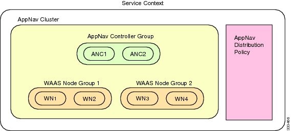
The Cisco AppNav solution consists of the following components (see Figure 4-1):
- AppNav Controller (ANC, or AC on the router): A device that intercepts network traffic and, based on an AppNav policy, distributes that traffic to one or more WAAS nodes for optimization. The device can be either of the following:
–![]() A Cisco WAAS appliance with a Cisco AppNav Controller Interface Module
A Cisco WAAS appliance with a Cisco AppNav Controller Interface Module
–![]() A Cisco router with Cisco IOS XE Release 3.9 (or a later release) running AppNav-XE (known as an AppNav-XE device in this document).
A Cisco router with Cisco IOS XE Release 3.9 (or a later release) running AppNav-XE (known as an AppNav-XE device in this document).
You cannot mix the ANCs on different platforms in the same AppNav cluster.
- AppNav Controller Group (ANCG, or ACG on the router): A group of AppNav Controllers that together provide the necessary intelligence for handling asymmetric flows and high availability. The ANCG is configured on the ANC. An ANCG can have up to eight WAAS appliance-based ANCs or four AppNav-XE-based ANCs, which must be on the same router platform with the same memory configuration.
- WAAS Node (known as a service node on the router): A Cisco WAAS optimization engine (Cisco WAE or Cisco WAVE appliance, NME-WAE or SM-SRE network module (for Cisco WAAS versions earlier than 6.4.x), or vWAAS instance, but not a Cisco WAAS Express device) that optimizes and accelerates traffic according to the optimization policies configured on the device. You can have up to 32 WAAS nodes in the cluster.
- WAAS Node Group (WNG, or SNG on the router): A group of WAAS nodes that services a particular set of traffic flows identified by AppNav policies. The WNG is configured on the ANC. You can have up to 32 WNGs in the cluster. (In the CLI and on the router, a WAAS node group is also known as a service node group.)
- AppNav Cluster: A group of all the ANC and WAAS node devices within a cluster.
- AppNav Context: The topmost entity that groups together one AppNav Controller Group (ANCG), one or more WAAS node groups (WNGs), and an associated AppNav policy. The AppNav context is configured on the ANC. When using a WAAS appliance ANC, there is only one AppNav context. However, when using an AppNav-XE ANC, you can define up to 32 AppNav contexts that are associated with different Virtual Routing and Forwarding (VRF) instances defined on the router.
Figure 4-1 Cisco AppNav Solution Components
Within a service context, WAAS devices can operate in one of two modes:
- Application accelerator: The device serves only as a Cisco WAAS node within the service context. It receives traffic from the ANC, optimizes the traffic, and returns the traffic to the ANC to be delivered to its destination. The WAAS node can be any kind of Cisco WAAS device or Cisco vWAAS instance.
- AppNav Controller: The device operates as an ANC that intercepts network traffic, and, based on a flow policy, distributes that traffic to one or more WAAS nodes for optimization. Only a Cisco WAVE appliance that contains a Cisco AppNav Controller Interface Module, or an AppNav-XE device, can operate as an ANC. A WAAS appliance ANC can also operate as a WAAS node and optimize traffic as part of a WNG.
AppNav Controller Deployment Models
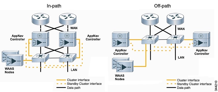
You can deploy Cisco WAAS appliance AppNav Controllers in your network in two ways (see Figure 4-2):
- In-path: The ANC is physically placed between one or more network elements, enabling traffic to traverse a bridge group configured on the device in inline mode.
- Off-path: The ANC works with the network infrastructure to intercept traffic through the Web Cache Communication Protocol (WCCP).
The ANC provides the same features in both in-path and off-path deployments. In either case, only ANCs participate in interception from the switch or router. The ANCs then distribute flows to WAAS nodes using a consistent and predictable algorithm that considers configured policies and WAAS node utilization.
Figure 4-2 shows that WAAS Nodes can be attached to either or both switches in the diagrams.
Figure 4-2 Cisco WAAS Appliance AppNav Deployment Models
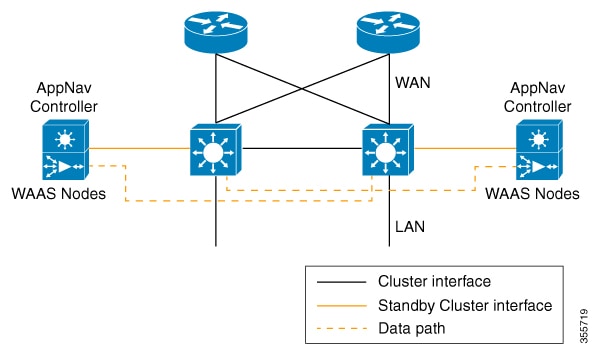
AppNav-XE ANCs have deployment models similar to the in-path diagram shown in Figure 4-2. You can see the specific deployment diagrams in the Cisco WAAS Central Manager cluster wizard when you choose a platform.
Combination mode
A Cisco WAAS device, which has an AppNav IOM card installed, can be configured to perform traffic interception using the AppNav module, and perform optimization as a single device. This is the combination mode as shown in the Figure 4-3:
Figure 4-3 Devices in Combination Mode (Off-Path Deployment)
A combination mode deployment is not recommended due the limitation of single point failure as explained below.
Limitation
In a combination deployment, a single AppNav IOM module failure impacts both the AppNav and Cisco WAAS functionality. All the traffic to a WAAS node is blocked leading to a loss of active sessions in Cisco WAAS. The WAAS node on the combination device becomes unreachable and is removed from the distribution list as shown below. Note that this is applicable for both In-path and Off-path deployments.
Figure 4-4 Devices Failure in Combination Mode (Off-Path Deployment)
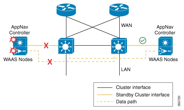
Figure 4-5 AppNav IOM and WAAS nodes in separate devices (off-path deployment)
You may experience some delay during cluster convergence when the AppNav IOM module comes back on line. Until then, other devices in the cluster will handle the new flows.
Recommendation
Considering the technical limitation in the combination mode, we strongly recommend to use separate devices for AppNav IOM and WAAS node to avoid a single point failure.
AppNav Controller Interface Modules
A Cisco WAAS appliance operating as an ANC requires a Cisco AppNav Controller Interface Module, that is similar to a standard Cisco WAVE appliance interface module, but contains additional hardware, including a network processor and high-speed ternary content addressable memory (TCAM), to provide intelligent and accelerated flow handling. The following AppNav Controller Interface Modules are supported:
- 1-GB copper 12-port AppNav Controller Interface Module
- 1-GB SFP 12-port AppNav Controller Interface Module
- 10-GB SFP+ 4-port AppNav Controller Interface Module
AppNav Controller Interface Module interfaces are configured differently to support either in-path or off-path models of deployment:
- In-path—The ANC operates in inline interception mode with at least one inline bridge group configured on the AppNav Controller Interface Module. A bridge group consists of two or more physical or logical (port channel) interfaces.
- Off-path—The ANC operates in WCCP interception mode with one physical or logical (standby or port channel) interface configured with an IP address.
Interfaces on the AppNav Controller Interface Module can have three functions:
- Interception—Used to receive traffic intercepted from the network and egress traffic to the network. The interception interface is implied based on the AppNav Controller placement and does not require explicit configuration for this function.
- Distribution—Used to distribute traffic to the WNs and receive egressed traffic from the WNs. The distribution interface is explicitly configured as the cluster interface for intracluster traffic and must be assigned an IP address.
- Management—A management interface can be optionally and exclusively designated for management traffic and isolated from the normal data path. We recommend that you use one of the appliance’s built-in interfaces for management traffic and reserve the high-performance interfaces on the AppNav Controller Interface Module for interception and distribution.
You should use separate interfaces for interception and distribution for best performance, but you can use the same interface for both functions.
AppNav Controller Interface Modules support port channel and standby logical interfaces. A port channel allows you to increase the bandwidth of a link by combining multiple physical interfaces into a single logical interface. A standby interface allows you to designate a backup interface in case of a failure.
Interfaces on the AppNav Controller Interface Module support the following:
- A maximum of seven port channels with up to eight physical interfaces combined into a single port channel group.
- A maximum of five bridge groups configured over the physical or logical interfaces.
Interfaces on the AppNav Controller Interface Module do not support the following:
AppNav Policy
The AppNav policy is a flow distribution policy that allows you to control how ANCs distribute traffic to the available WNs.
The AppNav policy consists of class maps that classify traffic according to one or more match conditions and a policy that contains rules that specify distribution actions to WNGs for each of the classes.
Class Maps
AppNav class maps classify traffic according to one or more of the following match conditions:
- Peer device ID: Matches traffic from one peer Cisco WAAS device, which could be handling traffic from a single site or a group of sites.
You can use this kind of matching to classify all traffic from a peer device that serves one branch office.
- Three-tuple of source IP, or destination IP, or destination port (matches traffic from a specific application).
For example, you can use this kind of matching to classify all HTTP traffic that uses port 80.
- A mix of one peer device ID and the source IP, or destination IP, or destination port (matches application-specific traffic from one site).
For example, you can use this kind of matching to classify all HTTP traffic that is from a peer device that serves the branch office.
The class-default class map (or APPNAV-class-default on AppNav-XE clusters) is a system-defined default class map that is defined to match any traffic. By default, it is placed in the last rule in each policy to handle traffic that is not matched by other classes.
Policies
An AppNav Controller matches incoming flows to class maps and the policy rules in a policy associate class maps with actions, such as distributing a flow to a particular WNG for optimization. The order in which rules are listed in the policy is important. Starting at the top of the policy, the first rule that matches a flow determines to which WNG it is distributed.
A policy rule can specify four kinds of actions to take on a flow:
- Specify the primary WNG to which to distribute the flow (required).
- Specify a backup WNG for distribution if the primary WNG is unavailable or overloaded (optional; not supported on AppNav-XE clusters).
The primary WNG receives all traffic until all WAAS nodes within the group become overloaded (reach 95 percent of the maximum number of connections) or are otherwise unavailable, and then traffic is distributed to the backup WNG. If a WAAS node in the first WNG becomes available, traffic is again distributed there. If all WAAS nodes in both the WNGs become overloaded, traffic is passed through unoptimized.
- Monitor the load on the application accelerator that corresponds to the application traffic matched by the class (optional).
If the monitored application accelerator on one WAAS node in a WNG becomes overloaded (reaches 95 percent of its maximum number of connections), the WAAS node is considered overloaded and traffic is directed to another WAAS node in the group. If all WAAS nodes become overloaded, traffic is distributed to the backup WNG. This application accelerator monitoring feature is useful for ensuring optimization for critical applications and is recommended for the MAPI and SMB accelerators.
For more information, see Nested Policies.
Within a WNG, flows are distributed among WAAS nodes using a hash. If a WAAS node reaches its maximum capacity or becomes unavailable, it is not sent new flows. New flows are sent to other available WAAS nodes in the WNG so that they can be optimized successfully. If an unavailable WAAS node later becomes available again, the same client/server pairs will hash to this WAAS node as before.

Note![]() If a WAAS node that is doing MAPI or ICA application acceleration becomes overloaded, flows associated with existing MAPI and ICA sessions continue to be sent to the same WN due to the requirement that the same WAAS node handles these types of flows. New MAPI and ICA flows, however, are distributed to other WAAS nodes.
If a WAAS node that is doing MAPI or ICA application acceleration becomes overloaded, flows associated with existing MAPI and ICA sessions continue to be sent to the same WN due to the requirement that the same WAAS node handles these types of flows. New MAPI and ICA flows, however, are distributed to other WAAS nodes.
The AppNav policy is specific to each ANC, though typically, all the ANCs in a cluster have the same policy. Each ANC consults its AppNav policy to determine which WNG to use for a given flow. Different ANCs in a cluster can have different AppNav policies, which allows you to customize distribution in certain cases. For example, when a cluster contains ANCs and WAAS nodes that are in different locations, it may be more desirable for an ANC to distribute traffic to WAAS nodes that are closer to it.
Note![]() On AppNav-XE clusters, the AppNav policy must be the same on all the ANCs in a context.
On AppNav-XE clusters, the AppNav policy must be the same on all the ANCs in a context.
Nested Policies
A policy rule can specify one nested policy, which allows traffic identified in a class to be subdivided and handled differently. Nested policies provide two advantages:
For example, you can define a policy that contains monitoring actions and apply it as a subpolicy to multiple classes in the primary policy.
- They provide a method of including class maps with both match-any and match-all characteristics into a single subclass.
The nested policy feature is designed for use with site-based classes (matched by peer ID) at the first-level and application-based subclasses (matched by IP address/port) at the second level. Only the first level policy can contain classes that use match peer conditions.
Note![]() AppNav-XE clusters do not support nested policies.
AppNav-XE clusters do not support nested policies.
Site and Application Affinity
About Site and Application Affinity
You can provision a WNG to serve specific peer locations (site affinity) or applications (application affinity) or a combination of the two. Using a WNG for site or application affinity provides the following advantages:
- Provisioning: Localize a class of traffic to achieve control over provisioning and performance monitoring. For example, a business-critical application such as Sharepoint or a business-critical site can be given assured capacity and monitored closely for performance.
- Enhanced application performance: Better compression performance is achieved by limiting data that belongs to a site, to one or a few WAAS nodes, which results in better utilization of the Data Redundancy Elimination (DRE) cache.
Figure 4-6 depicts how sites and applications can be associated with node groups. The following WNGs are defined:
- WNG-1: Consists of two WAAS nodes that process flows coming only from sites A and B.
- WNG-2: Consists of two WAAS nodes that process HTTP and SSL flows from any site. Whether HTTP and SSL flows from Site A and Site B should be processed by WNG-2 or WNG-1 is determined by the order of rules in the policy.
- WNG-3: Consists of two WAAS nodes that process MAPI flows coming from any site. Whether MAPI flows from Site A and Site B should be processed by WNG-3 or WNG-1 is determined by the order of rules in the policy.
- WNG-4: Consists of three WAAS nodes. The class-default class is applied to this WNG so that it all the flows that do not match any other class map are sent to it.
Figure 4-6 Flow Distribution Using Site and Application Affinity
Site Affinity Operating Guidelines
Consider the following operating guidelines for site affinity:
- Site affinity provides you with the ability to always send all the traffic from one site to a specific WNG, which allows you to reserve optimization capacity for critical sites and to improve compression performance through better utilization of the DRE cache.
- Traffic from any location, not just a single site, can be matched in a class map and associated with a WNG.
- You can implement site affinity by configuring a class map that matches the device ID of the WAE in the site. If a site has more than one WAE in a WCCP farm or a serial inline cluster, specify multiple device IDs in the class map. Next, associate the class map with a distribution action to a WNG in a policy rule. You can also identify sites using source IP addresses or subnets in the class map, if you know what IP addresses are used in the site and keep the policy configuration consistent with site IP addresses. However, we recommend that you use peer device IDs when configuring site affinity.
- A peer ID-based class map works only for matching flows that carry the WAAS auto discovery TCP options. If you configure a class to match a site peer ID at the data center, the same class does not match flows that originate in the other direction, such as those flows that originate from the data center and go back to the same site. Such flows are usually small in number compared to the site-to-data center flows.
–![]() If you want flows in both directions to go to the same WNG, you must configure two class maps: one to match in the site-to-data center direction, typically using the site device ID; and another to match the data center-to-site direction, using destination IP subnets belonging to the site. Both class maps can be configured to distribute traffic to the same WNG. A mesh network is a specific use case where flows can originate in either direction.
If you want flows in both directions to go to the same WNG, you must configure two class maps: one to match in the site-to-data center direction, typically using the site device ID; and another to match the data center-to-site direction, using destination IP subnets belonging to the site. Both class maps can be configured to distribute traffic to the same WNG. A mesh network is a specific use case where flows can originate in either direction.
–![]() If the site WAE is in overload or does not mark the SYN packet with auto discovery options for any other reason, the ANC cannot match it to the peer match class map.
If the site WAE is in overload or does not mark the SYN packet with auto discovery options for any other reason, the ANC cannot match it to the peer match class map.
Application Affinity Operating Guidelines
Consider the following operating guidelines for application affinity:
- Application affinity gives you the ability to always send certain application traffic to a specific WNG, which allows you to reserve optimization capacity for different applications depending on business priorities.
- In the context of AppNav flow distribution, an application is defined using a three-tuple of source IP, destination IP, and destination TCP port. The actual type of traffic does not matter for flow distribution. For example, you can use separate WNGs for HTTP traffic that is addressed to different destination ports or different server IP addresses. Destination IP and ports are most useful in using application affinity, but having the source IP also helps you to define the traffic of interest.
- A small number of protocols, such as FTP, use dynamic destination ports. An FTP server in active mode originates a data connection back to the FTP client using a dynamic destination port. This port is exchanged over the control channel from client to server using the well-defined destination port 21. Consider trying to define a class map for FTP. Because the destination port is not known in advance, you cannot map both control and data connections to the same class.
In this case, we recommend that you use the client IP addresses or subnets to match the destination IP addresses for the data connections. You must configure two class maps: one for the control channel, using destination port 21, and another for the data channel, using destination IP addresses. You can configure policy rules so that both class maps distribute traffic to the same WNG.
Default Policy Behavior
The following default class maps are provided:
- Citrix: Matches traffic for destination port 1494 and 2598
- epmap: Matches traffic for destination port 135
- HTTP: Matches traffic for destination ports 80, 3128, 8000, 8080, and 8088
- HTTPS: Matches traffic for destination port 443
- MAPI: Matches traffic for the MS RPC MAPI application (dynamic port assignment)
- RTSP: Matches traffic for destination ports 554 and 8554
- class-default or APPNAV-class-default:Matches any TCP traffic. This class map cannot be edited or deleted.
If you use the Cisco WAAS Central Manager AppNav Cluster wizard to create an AppNav Cluster, the wizard creates a default policy. This policy is assigned by default to all the ANCs in a cluster and contains only the class-default policy rule (APPNAV-class-default on AppNav-XE clusters) that has the following characteristics:
- Matches class-default (any TCP) traffic (APPNAV-class-default on AppNav-XE clusters).
- Distributes class-default traffic to the default WNG, which includes all the WNs created by the wizard, with no backup WNG specified.
- Contains the waas_app_default nested policy, which provides application monitoring for each of the default class maps. (Not used on AppNav-XE clusters, which do not support nested policies.)
When you use the Central Manager to define a policy rule for any class that uses peer matching or source or destination IP address matching (but not port matching), it automatically adds the waas_app_default policy as a nested policy. The waas_app_default policy is created by the system and monitors all application accelerators, so you do not need to manually add application accelerator monitoring to your policy rules.
If you do not use the Cisco WAAS Central Manager AppNav Cluster Wizard to create a cluster, there is no default flow distribution. Therefore, if an incoming flow does not match any class in the AppNav policy, it is not distributed to any WNG; instead, it is passed through.
If a WNG is defined, but is not used in any policy rule, it does not receive any flows. If a policy is defined, but not applied to an ANC, it does not take effect.
The default action for a policy rule is none, which is context dependent: in a top-level policy, it means pass-through, and if the policy is nested, it means inherit-the-parent-policy-rule action.
Prerequisites for AppNav Deployment
AppNav deployment has the following prerequisites:
- Each Cisco WAAS appliance that is to be used as an AppNav Controller must contain a Cisco AppNav Controller Interface Module.
- Each Cisco WAAS appliance AppNav Controller must be configured in appnav-controller device mode.
If you are using AppNav-XE devices, they must be registered and activated in the Cisco WAAS Central Manager before the Cisco WAAS Central Manager can manage them. For more information on registering AppNav-XE devices, see Managing Cisco IOS Router Devices in the chapter “Configuring Other System Settings” .
Note![]() You can use an AppNav-XE device in a small deployment without a Cisco WAAS Central Manager by configuring the cluster from the AppNav-XE device CLI. For details, see the corresponding router documentation on www.cisco.com.
You can use an AppNav-XE device in a small deployment without a Cisco WAAS Central Manager by configuring the cluster from the AppNav-XE device CLI. For details, see the corresponding router documentation on www.cisco.com.
Guidelines and Limitations for AppNav Deployment
AppNav deployment has the following configuration guidelines and limitations:
–![]() 8 ANCs if you are using WAAS appliances, or 4 ANCs if you are using AppNav-XE devices
8 ANCs if you are using WAAS appliances, or 4 ANCs if you are using AppNav-XE devices
–![]() 32 WAAS nodes, or 64 WAAS nodes if you are configuring an AppNav-XE cluster.
32 WAAS nodes, or 64 WAAS nodes if you are configuring an AppNav-XE cluster.
–![]() A service context if you are using WAAS appliances or 32 service contexts if you are using AppNav-XE devices
A service context if you are using WAAS appliances or 32 service contexts if you are using AppNav-XE devices
- You cannot mix ANCs on different platforms in an AppNav Cluster.
- All the ANCs in an ANCG must have the same set of ANCs and WNGs in their configuration.
- All the WAAS nodes in a WNG must have identical optimization policies configured.
- On AppNav-XE devices, all the ANCs in the cluster must have an identical AppNav configuration (class maps, policy maps, VRFs, and so forth). In an AppNav- XE cluster, all AppNav-XE devices must be of the same hardware model.
- AppNav class maps and policies can be configured only at the cluster level, not at the device level, from the Central Manager. At the device level, class maps and policies can only be viewed.
- You can define the following maximum policy entities within a service context on a Cisco WAAS appliance cluster:
–![]() 64 AppNav policies, though only one policy is actively bound to the service context and used for flow distribution on a given ANC
64 AppNav policies, though only one policy is actively bound to the service context and used for flow distribution on a given ANC
–![]() 32 match conditions per class map
32 match conditions per class map
–![]() 1000 rules per AppNav policy
1000 rules per AppNav policy
- There is no fail-to-wire capability on AppNav Controller Interface Module interfaces configured in bridge groups for inline mode, which would allow traffic to bypass the interface if the device fails or loses power. Therefore, if you are using inline mode, we recommend that you deploy two or more AppNav Controller appliances to provide high availability.
- On AppNav-XE devices, do not use VRF to access the WNs from the ANCs.
- On AppNav-XE devices, do not use a port channel between the ANCs and the WNs because traffic is transmitted over a GRE tunnel and all traffic is switched on one link.
- An AppNav-XE device cannot intercept Overlay Transport Virtualization (OTV) traffic that is configured on the interception interface.
- If you have configured an AppNav-XE device by using the EZConfig CLI utility on the router, you cannot manage the AppNav-XE device with the Cisco WAAS Central Manager. To switch between managing the AppNav-XE device with the EZConfig utility on the router and the Cisco WAAS Central Manager, either delete the AppNav-XE cluster and contexts by using the router CLI or register the devices with the Cisco WAAS Central Manager and wait for the device configuration to synchronize (about 10 minutes). Then re-create the cluster and contexts by using the Central Manager. To switch from using the Cisco WAAS Central Manager to manage the AppNav-XE configuration to using the router CLI, delete the cluster and contexts from the Cisco WAAS Central Manager and then re-create the cluster and contexts by using the router CLI or EZConfig utility.
- When configuring a nested class map as a match condition from the CLI you can nest up to four layers. This configuration does not show up as an Force Device Group conflict on the Cisco WAAS Central Manager page but is listed as an exception in the error logs of the CLI.
Configuring an AppNav Cluster
This section contains the following topics:
- Task Flow for Configuring an AppNav Cluster
- Configuring WAAS Device Interfaces
- Creating a New AppNav Cluster with the AppNav Cluster Wizard
- Configuring AppNav Policies
- Configuring AppNav Controller ACLs
- Configuring AppNav Cluster Settings
- Configuring AppNav Controller Settings
- Configuring WAAS Node Settings
- Configuring Cisco WAAS Node Group Settings
- ConfiguringCisco AppNav Cluster Settings for a Cisco WAAS Node
- Adding and Removing Devices from the AppNav Cluster
Task Flow for Configuring an AppNav Cluster
You must complete the following steps to configure an AppNav Cluster:
1.![]() Install and configure the individual ANC and WN devices with basic network settings. For WAAS appliances, see Configuring WAAS Device Interfaces. For AppNav-XE devices, see the router documentation.
Install and configure the individual ANC and WN devices with basic network settings. For WAAS appliances, see Configuring WAAS Device Interfaces. For AppNav-XE devices, see the router documentation.
2.![]() Use the Cisco Central Manager AppNav Cluster Wizard to create a cluster and configure the interception mode, configure cluster settings, choose cluster devices, configure VRFs (for AppNav-XE), configure traffic interfaces, and configure WCCP settings if you are using WCCP. AppNav-XE. See Creating a New AppNav Cluster with the AppNav Cluster Wizard.
Use the Cisco Central Manager AppNav Cluster Wizard to create a cluster and configure the interception mode, configure cluster settings, choose cluster devices, configure VRFs (for AppNav-XE), configure traffic interfaces, and configure WCCP settings if you are using WCCP. AppNav-XE. See Creating a New AppNav Cluster with the AppNav Cluster Wizard.
3.![]() (Optional) Configure AppNav class maps. This step is necessary only if you want to customize the default class map configuration. The system adds several default class maps that match traffic corresponding to most of the application accelerators and a class-default class map that matches all traffic. See Configuring a Class Map on a Cisco WAAS Appliance AppNav Cluster.
(Optional) Configure AppNav class maps. This step is necessary only if you want to customize the default class map configuration. The system adds several default class maps that match traffic corresponding to most of the application accelerators and a class-default class map that matches all traffic. See Configuring a Class Map on a Cisco WAAS Appliance AppNav Cluster.
4.![]() (Optional) Configure an AppNav policy. This step is necessary only if you want to customize the default policy. The system adds a default policy that distributes all traffic to the WNG-Default WNG, which is the node group into which all WNs are grouped by default. See Configuring Rules Within an AppNav Policy.
(Optional) Configure an AppNav policy. This step is necessary only if you want to customize the default policy. The system adds a default policy that distributes all traffic to the WNG-Default WNG, which is the node group into which all WNs are grouped by default. See Configuring Rules Within an AppNav Policy.
5.![]() (Optional) Configure WAAS node optimization class maps and policy rules. This step is necessary only if you want to customize the default optimization policy that is listed in Appendix A, “Predefined Optimization Policy” .
(Optional) Configure WAAS node optimization class maps and policy rules. This step is necessary only if you want to customize the default optimization policy that is listed in Appendix A, “Predefined Optimization Policy” .
6.![]() (Optional) Configure an interception ACL on Cisco WAAS appliance ANCs. See Configuring AppNav Controller ACLs.
(Optional) Configure an interception ACL on Cisco WAAS appliance ANCs. See Configuring AppNav Controller ACLs.
Operating Guidelines for AppNav Clusters and Service Nodes
- Use the Cisco WAAS Central Manager, only, to create AppNav cluster. Do not use the Cisco WAAS CLI to create the AppNav cluster.
- Use the Cisco WAAS Central Manager, only, to add, modify, or delete a Service Node or Service Context. Do not use the Cisco WAAS CLI for any of these operations.
Note![]() If cluster configuration changes are done using the Cisco WAAS CLI, then the cluster configuration between the device and the Cisco WAAS Central Manager will go out of sync, which will result in incorrect cluster-configuration information displayed in the Cisco WAAS Central Manager GUI.
If cluster configuration changes are done using the Cisco WAAS CLI, then the cluster configuration between the device and the Cisco WAAS Central Manager will go out of sync, which will result in incorrect cluster-configuration information displayed in the Cisco WAAS Central Manager GUI.
Configuring WAAS Device Interfaces
Before using the AppNav Cluster wizard to create an AppNav Cluster, connect the Cisco WAAS device interfaces and configure the management interfaces. Configuration differs depending on whether management traffic uses a separate interface or shares the traffic handling interface.
This section contains the following topics:
- Interface Configuration with a Separate Management Interface
- Interface Configuration with a Shared Management Interface
- Interface Configuration Considerations
For more information about device interface configuration, see the chapter “Configuring Network Settings” .For more information about configuring a bridge group for inline interception mode, see Configuring Inline Operation on ANCs in the chapter “Configuring Traffic Interception” .
See your Cisco router documentation for information on configuring interfaces on AppNav-XE devices.
Interface Configuration with a Separate Management Interface
Cisco AppNav Controller as Separate Management Interface
To configure management traffic to use a Cisco AppNav Controller as a dedicated interface that is separate from the traffic data path, follow these steps.
Step 1![]() Connect the last AppNav Controller Interface Module port to the switch/router port for the cluster traffic. For example, this port is GigabitEthernet 1/11 on a 12-port module or TenGigabitEthernet 1/3 on a 4-port module.
Connect the last AppNav Controller Interface Module port to the switch/router port for the cluster traffic. For example, this port is GigabitEthernet 1/11 on a 12-port module or TenGigabitEthernet 1/3 on a 4-port module.
Step 2![]() Connect a built-in Ethernet port to the switch/router port for the management interface.
Connect a built-in Ethernet port to the switch/router port for the management interface.
Step 3![]() For an in-path (inline) deployment, connect the first pair of ports on the AppNav Controller Interface Module, for example, GigabitEthernet 1/0 (LAN) and GigabitEthernet 1/1 (WAN) for bridge 1, to the corresponding switch/router ports.
For an in-path (inline) deployment, connect the first pair of ports on the AppNav Controller Interface Module, for example, GigabitEthernet 1/0 (LAN) and GigabitEthernet 1/1 (WAN) for bridge 1, to the corresponding switch/router ports.
If the ANC is connected to a second router for a dual inline deployment, connect the second pair of ports on the AppNav Controller Interface Module, for example, GigabitEthernet 1/2 (LAN) and GigabitEthernet 1/3 (WAN) for bridge 2, to corresponding switch/router ports.
Step 4![]() Use the device setup command to configure the following settings:
Use the device setup command to configure the following settings:
- Configure the device mode as AppNav Controller.
- Configure the IP address and netmask of the built-in management port.
- Configure the built-in management port as the primary interface.
- Configure the other network and basic settings (default gateway, DNS, NTP server, and so forth).
- Register the device with the Central Manager by entering the Central Manager IP address.
Step 5![]() Configure the IP address and netmask of the last AppNav Controller Interface Module port and do not use DHCP. You can also configure these settings through the AppNav Cluster wizard.
Configure the IP address and netmask of the last AppNav Controller Interface Module port and do not use DHCP. You can also configure these settings through the AppNav Cluster wizard.
Cisco WAAS Node as Separate Management Interface
To configure management traffic to use a Cisco WAAS Node as a dedicated interface that is separate from the traffic data path, follow these steps.
Step 1![]() Connect a built-in Ethernet port to the switch/router port for management interface.
Connect a built-in Ethernet port to the switch/router port for management interface.
Step 2![]() Use the device setup command to configure the following settings:
Use the device setup command to configure the following settings:
–![]() Configure the device mode as Application Accelerator.
Configure the device mode as Application Accelerator.
–![]() Configure the IP address and netmask of the built-in management port.
Configure the IP address and netmask of the built-in management port.
–![]() Configure the built-in management port as the primary interface.
Configure the built-in management port as the primary interface.
–![]() Configure the other network and basic settings (default gateway, DNS, NTP server, and so forth).
Configure the other network and basic settings (default gateway, DNS, NTP server, and so forth).
–![]() Register the device with the Central Manager by entering the Central Manager IP address.
Register the device with the Central Manager by entering the Central Manager IP address.
Interface Configuration with a Shared Management Interface
Cisco AppNav Controller as Shared Management Interface
To configure management traffic to use a Cisco AppNav Controller as an interface shared by the traffic data path, follow these steps.
Step 1![]() Connect the last AppNav Controller Interface Module port to the switch/router port for cluster traffic. For example, this port is GigabitEthernet 1/11 on a 12-port module or TenGigabitEthernet 1/3 on a 4-port module.
Connect the last AppNav Controller Interface Module port to the switch/router port for cluster traffic. For example, this port is GigabitEthernet 1/11 on a 12-port module or TenGigabitEthernet 1/3 on a 4-port module.
Step 2![]() For an in-path (inline) deployment, connect the first pair of ports on the AppNav Controller Interface Module, for example, GigabitEthernet 1/0 (LAN) and GigabitEthernet 1/1 (WAN) for bridge 1, to corresponding switch/router ports.
For an in-path (inline) deployment, connect the first pair of ports on the AppNav Controller Interface Module, for example, GigabitEthernet 1/0 (LAN) and GigabitEthernet 1/1 (WAN) for bridge 1, to corresponding switch/router ports.
If the ANC is connected to a second router for a dual inline deployment, connect the second pair of ports on the AppNav Controller Interface Module, for example, GigabitEthernet 1/2 (LAN) and GigabitEthernet 1/3 (WAN) for bridge 2, to corresponding switch/router ports.
Step 3![]() Use the device setup command to configure the following settings:
Use the device setup command to configure the following settings:
–![]() Configure the device mode as AppNav Controller.
Configure the device mode as AppNav Controller.
–![]() Configure the IP address and netmask of the last AppNav Controller Interface Module port. Do not use DHCP.
Configure the IP address and netmask of the last AppNav Controller Interface Module port. Do not use DHCP.
–![]() Configure the last AppNav Controller Interface Module port as the primary interface.
Configure the last AppNav Controller Interface Module port as the primary interface.
–![]() Configure the other network and basic settings (default gateway, DNS, NTP server, and so forth).
Configure the other network and basic settings (default gateway, DNS, NTP server, and so forth).
–![]() Register the device with the Central Manager by entering the Central Manager IP address.
Register the device with the Central Manager by entering the Central Manager IP address.
Cisco WAAS Node as Shared Management Interface
To configure management traffic to use a Cisco WAAS node as an interface shared by the traffic data path, follow these steps.
Step 1![]() Connect a built-in Ethernet port to the switch/router port for management interface.
Connect a built-in Ethernet port to the switch/router port for management interface.
Step 2![]() Use the device setup command to configure the following settings:
Use the device setup command to configure the following settings:
–![]() Configure the device mode as Application Accelerator.
Configure the device mode as Application Accelerator.
–![]() Configure the IP address and netmask of the built-in management port.
Configure the IP address and netmask of the built-in management port.
–![]() Configure the built-in management port as the primary interface.
Configure the built-in management port as the primary interface.
–![]() Configure the other network and basic settings (default gateway, DNS, NTP server, and so forth).
Configure the other network and basic settings (default gateway, DNS, NTP server, and so forth).
–![]() Register the device with the Central Manager by entering the Central Manager IP address.
Register the device with the Central Manager by entering the Central Manager IP address.
Interface Configuration Considerations
Consider the following guidelines for Cisco WAAS device interface configuration:
- On an ANC, the intercepted traffic must go through an interface on the AppNav Controller Interface Module.
- On an ANC that also serves as a WN, the cluster interface is the same as the interception interface.
- On a WN, cluster traffic can be handled on any interface, either built-in or on an interface module.
- To simplify AppNav deployment, the AppNav Cluster Wizard uses the following conventions for configuring the AppNav Controller Interface Module ports on an ANC:
–![]() The default port for cluster traffic is the last port on the module, for example, GigabitEthernet 1/11 on a 12-port module or TenGigabitEthernet 1/3 on a 4-port module.
The default port for cluster traffic is the last port on the module, for example, GigabitEthernet 1/11 on a 12-port module or TenGigabitEthernet 1/3 on a 4-port module.
–![]() For an in-path (inline) deployment, the default interception bridge is the first pair of ports on the module, for example, GigabitEthernet 1/0 (LAN) and GigabitEthernet 1/1 (WAN) for bridge 1. If the ANC is connected to a second router for a dual inline deployment, the default second interception bridge is the second pair of ports on the module, for example, GigabitEthernet 1/2 (LAN) and GigabitEthernet 1/3 (WAN) for bridge 2.
For an in-path (inline) deployment, the default interception bridge is the first pair of ports on the module, for example, GigabitEthernet 1/0 (LAN) and GigabitEthernet 1/1 (WAN) for bridge 1. If the ANC is connected to a second router for a dual inline deployment, the default second interception bridge is the second pair of ports on the module, for example, GigabitEthernet 1/2 (LAN) and GigabitEthernet 1/3 (WAN) for bridge 2.
The AppNav Cluster Wizard uses four predefined deployment models to help simplify configuration on a Cisco WAAS appliance. Each deployment model expects interfaces to be connected and configured in a particular way, except for the Custom option, which allows you to configure interfaces in any way. Before you run the wizard with one of the four predefined models, the required interfaces must be in either of these states:
- Not configured with an IP address and netmask and not used as part of another logical interface. (However, the last port on the AppNav Controller Interface Module can be configured with an IP address because it is the default port for cluster traffic.)
The wizard configures all required traffic interface settings.
- Configured as expected by the wizard according to the following predefined deployment model expectations:
Single AppNav Controller WCCP Interception
With a 12-port AppNav Controller Interface Module:
With a 4-port AppNav Controller Interface Module:
Dual AppNav Controllers WCCP Interception
With a 12-port AppNav Controller Interface Module:
- Port channel 1—Contains ports GigabitEthernet 1/10 and 1/11
- Port channel 2—Contains ports GigabitEthernet 1/8 and 1/9
- Standby group 1—Contains interfaces Port channel 1 (primary) and Port channel 2
- Cluster interface—Standby Group 1
With a 4-port AppNav Controller Interface Module:
- Standby group 1—Contains ports GigabitEthernet 1/2 and 1/3 (primary)
- Cluster interface—Standby Group 1
Creating a New AppNav Cluster with the AppNav Cluster Wizard
See the topic for the type of AppNav Cluster you want to create:
Creating a Cisco WAAS Appliance AppNav Cluster with the AppNav Cluster Wizard
- Set up the individual ANC and WN devices as described in Configuring WAAS Device Interfaces.
- Ensure that all ANCs are configured for AppNav Controller device mode. If you need to change the device mode, see Changing Device Mode in the chapter “Planning Your Cisco WAAS Network” .
- Use the Central Manager to configure basic settings for all devices such as NTP server, AAA, logging, and so on.
To create a new AppNav Cluster using the AppNav Cluster wizard, follow these steps:
Step 1![]() From the Cisco WAAS Central Manager menu, choose AppNav Clusters > All AppNav Clusters.
From the Cisco WAAS Central Manager menu, choose AppNav Clusters > All AppNav Clusters.
The Manage AppNav Clusters window appears.
Step 2![]() Click the AppNav Cluster Wizard icon in the taskbar of the Manage AppNav Clusters area.
Click the AppNav Cluster Wizard icon in the taskbar of the Manage AppNav Clusters area.
The AppNav Cluster Wizard window appears.
Step 3![]() From the AppNav platform drop-down list, choose WAVE Appliance.
From the AppNav platform drop-down list, choose WAVE Appliance.
Step 4![]() From the Deployment model drop-down list, choose one of the following deployment models that matches your deployment:
From the Deployment model drop-down list, choose one of the following deployment models that matches your deployment:
To select a deployment model other than custom, go through the Interface Configuration Considerations.
Step 5![]() (Optional) If you chose the Custom deployment model, from the Interception method drop-down list, choose the WCCP or Inline interception method and click Next.
(Optional) If you chose the Custom deployment model, from the Interception method drop-down list, choose the WCCP or Inline interception method and click Next.
Step 6![]() Define the cluster settings by entering the following information:
Define the cluster settings by entering the following information:
- In the Name field, enter a unique name for the cluster. This name should be different from the name used for a Device Group. Otherwise, an error message stating that the name already exists is displayed. Use only letters, numbers, hyphen, and underscore, up to a maximum of 32 characters and beginning with a letter. This name should also be different from the WAE/Router hostname.
- (Optional) In the Description field, enter a description of the cluster. Use only letters and numbers, up to a maximum of 200 characters.
- Check the Disable Distribution check box if you want make the cluster operate in monitoring mode, otherwise, it is activated when the wizard finishes. In monitoring mode, all traffic is passed through instead of being distributed to WAAS nodes.
Step 8![]() Choose the ANC and WAAS node devices that you want to be part of the cluster:
Choose the ANC and WAAS node devices that you want to be part of the cluster:
a.![]() Choose up to eight ANCs in the AppNav Controller device list by clicking the check box next to the device names. You can use the filter settings in the taskbar to filter the device list.
Choose up to eight ANCs in the AppNav Controller device list by clicking the check box next to the device names. You can use the filter settings in the taskbar to filter the device list.
b.![]() (Optional) To enable optimization on the ANC devices, check the Enable WAN optimization on selected AppNav Controller(s) check box (it may be enabled or disabled by default, depending on the deployment model you chose).
(Optional) To enable optimization on the ANC devices, check the Enable WAN optimization on selected AppNav Controller(s) check box (it may be enabled or disabled by default, depending on the deployment model you chose).
c.![]() Choose up to 32 WAAS nodes in the WAAS Nodes device list by clicking the check box next to the device names. You can use the filter settings in the taskbar to filter the device list.
Choose up to 32 WAAS nodes in the WAAS Nodes device list by clicking the check box next to the device names. You can use the filter settings in the taskbar to filter the device list.
If there are devices that are ineligible to join the cluster, click Show Ineligible Devices to see them and the reasons why they are ineligible. You can use the filter settings to filter the list.
Step 10![]() Verify the cluster interface, IP address, and netmask for each device in the cluster. The wizard automatically selects recommended cluster interfaces that should be configured. To edit the IP address and netmask settings for a device, choose the device and click the Edit taskbar icon.
Verify the cluster interface, IP address, and netmask for each device in the cluster. The wizard automatically selects recommended cluster interfaces that should be configured. To edit the IP address and netmask settings for a device, choose the device and click the Edit taskbar icon.
Note![]() This window does not appear if you are configuring a custom cluster.
This window does not appear if you are configuring a custom cluster.
Step 11![]() Click Finish if you are using inline interception (and you are done) or click Next if you are using WCCP interception (and continue with the following steps for WCCP).
Click Finish if you are using inline interception (and you are done) or click Next if you are using WCCP interception (and continue with the following steps for WCCP).
Step 12![]() (Optional) Configure the WCCP settings for the ANC. This window does not appear if you are configuring an inline cluster.
(Optional) Configure the WCCP settings for the ANC. This window does not appear if you are configuring an inline cluster.
For details about configuring WCCP, see Configuring WCCP on WAEs in the chapter “Configuring Cisco AppNav” .
a.![]() Ensure that the Enable WCCP Service check box is checked if you want to enable WCCP. This item appears only if you are defining a custom cluster.
Ensure that the Enable WCCP Service check box is checked if you want to enable WCCP. This item appears only if you are defining a custom cluster.
b.![]() Verify the single WCCP service ID of 61 (default), or change it if desired.
Verify the single WCCP service ID of 61 (default), or change it if desired.
Configure only this single WCCP service on both the ingress and egress ports of the router doing WCCP redirection to this ANC.
c.![]() (Optional) If you want to enable two WCCP services, uncheck the Enable Single Service Mode check box (it is checked by default because two WCCP services are not required). The automatically assigned second service ID number is shown in the Service ID2 field.
(Optional) If you want to enable two WCCP services, uncheck the Enable Single Service Mode check box (it is checked by default because two WCCP services are not required). The automatically assigned second service ID number is shown in the Service ID2 field.
d.![]() From the Redirect Method drop-down list, choose the WCCP L2 or WCCP GRE redirect method. For details on the redirect method, see Configuring or Viewing the WCCP Settings on ANCs in the chapter “Configuring Traffic Interception” . This item appears only if you are defining a custom cluster.
From the Redirect Method drop-down list, choose the WCCP L2 or WCCP GRE redirect method. For details on the redirect method, see Configuring or Viewing the WCCP Settings on ANCs in the chapter “Configuring Traffic Interception” . This item appears only if you are defining a custom cluster.
e.![]() (Optional) If you do not want to use the default gateway defined on the device, uncheck the Use Default Gateway as WCCP Router check box. Enter the address of one or more WCCP routers, separated by commas, in the WCCP Routers field.
(Optional) If you do not want to use the default gateway defined on the device, uncheck the Use Default Gateway as WCCP Router check box. Enter the address of one or more WCCP routers, separated by commas, in the WCCP Routers field.
f.![]() Click Advanced WCCP Settings to configure additional settings, as needed. For more information on these fields, see Configuring or Viewing the WCCP Settings on ANCs in the chapter the chapter “Configuring Traffic Interception” . This item appears only if you are defining a custom cluster.
Click Advanced WCCP Settings to configure additional settings, as needed. For more information on these fields, see Configuring or Viewing the WCCP Settings on ANCs in the chapter the chapter “Configuring Traffic Interception” . This item appears only if you are defining a custom cluster.
Step 13![]() Click Next. If you are configuring multiple ANCs, a similar window is shown for each ANC.
Click Next. If you are configuring multiple ANCs, a similar window is shown for each ANC.
Step 14![]() Configure the interception and cluster interface settings for each device. The Cluster Interface wizard only appears if you are defining a custom cluster, with one window for each device in the cluster:
Configure the interception and cluster interface settings for each device. The Cluster Interface wizard only appears if you are defining a custom cluster, with one window for each device in the cluster:
a.![]() Configure individual interception interfaces, port channels, standby interfaces, and bridge interfaces (for inline only), as needed, on the device by using the graphical interface wizard. If you are configuring an inline ANC, you must define a bridge interface with two physical or port-channel interfaces (or one of each) for interception. For details on how to use the wizard, see Configuring Interfaces with the Graphical Interface Wizard.
Configure individual interception interfaces, port channels, standby interfaces, and bridge interfaces (for inline only), as needed, on the device by using the graphical interface wizard. If you are configuring an inline ANC, you must define a bridge interface with two physical or port-channel interfaces (or one of each) for interception. For details on how to use the wizard, see Configuring Interfaces with the Graphical Interface Wizard.
b.![]() From the Cluster Interface drop-down list, choose the interface to be used for intracluster traffic.
From the Cluster Interface drop-down list, choose the interface to be used for intracluster traffic.
Step 15![]() Click Next. If you are configuring multiple devices, a similar window is shown for each device.
Click Next. If you are configuring multiple devices, a similar window is shown for each device.
Step 16![]() Click Finish to save the cluster configuration.
Click Finish to save the cluster configuration.
By default, the Cluster Interface wizard assigns all the WNs to a default WNG named WNG-Default. You can create additional WNGs, as described in Adding a New WAAS Node to the Cluster. You can reassign WNs to different WNGs, as described in Configuring WAAS Node Settings.
After you create an AppNav Cluster, it is shown in the Manage AppNav Clusters list. For details on monitoring the cluster, see Monitoring an AppNav Cluster.
Creating a Cisco AppNav-XE Cluster with the AppNav Cluster Wizard
- Set up the individual ANC and WN devices. Configure Cisco WAAS node device interfaces, as described in Configuring WAAS Device Interfaces. Configure ANC device interfaces, as described in the router documentation on www.cisco.com.
- Configure any desired VRF instances on the ANC routers.
- Register all AppNav-XE devices with the Central Manager and ensure they are activated in the Central Manager. For more information on registering AppNav-XE devices, see Managing Cisco IOS Router Devices in the chapter “Configuring Other System Settings” .
To create a new Cisco AppNav-XE cluster by using the wizard, follow these steps:
Step 1![]() From the Cisco WAAS Central Manager menu, choose AppNav Clusters > All AppNav Clusters.
From the Cisco WAAS Central Manager menu, choose AppNav Clusters > All AppNav Clusters.
The Manage AppNav Clusters window appears.
Step 2![]() Click the AppNav Cluster Wizard icon in the taskbar of the Manage AppNav Clusters area. The Cluster Wizard window appears.
Click the AppNav Cluster Wizard icon in the taskbar of the Manage AppNav Clusters area. The Cluster Wizard window appears.
Step 3![]() From the AppNav Platform drop-down list, choose one of the following AppNav-XE platforms to use for your deployment. All ANCs must use the same platform type with identical memory configurations.
From the AppNav Platform drop-down list, choose one of the following AppNav-XE platforms to use for your deployment. All ANCs must use the same platform type with identical memory configurations.
Step 5![]() Define the cluster settings by entering the following information:
Define the cluster settings by entering the following information:
- In the Cluster Name field, enter a name for the cluster. Use only letters, numbers, hyphen, and underscore. A maximum of 32 characters, beginning with a letter, can be entered.
- (Optional) In the Description field, enter a description of the cluster. Use only letters and numbers. A maximum of 200 characters can be entered.
- (Optional) From the WAAS Cluster ID drop-down list, choose a cluster ID that is unique for this cluster in your Cisco WAAS network. Only unused cluster IDs are shown.
Step 6![]() Choose the ANC and WAAS node devices that you want to be part of the cluster:
Choose the ANC and WAAS node devices that you want to be part of the cluster:
a.![]() Choose up to four AppNav-XE devices of the same platform type in the AppNav Controller device list by clicking the check box next to the device names. You can use the filter settings in the taskbar to filter the device list.
Choose up to four AppNav-XE devices of the same platform type in the AppNav Controller device list by clicking the check box next to the device names. You can use the filter settings in the taskbar to filter the device list.
b.![]() Choose up to 64 WAAS nodes in the WAAS Nodes device list by clicking the check box next to the device names. You can use the filter settings in the taskbar to filter the device list.
Choose up to 64 WAAS nodes in the WAAS Nodes device list by clicking the check box next to the device names. You can use the filter settings in the taskbar to filter the device list.
If there are devices that are ineligible to join the cluster, click Show Ineligible Devices to see them and the reasons why they are ineligible. You can use the filter settings to filter the list.
Step 8![]() Choose the VRF instances to associate with the service context by checking the box next to each VRF instance that you want to use. If you choose the VRF default, you cannot choose other VRFs. If you choose multiple VRFs, they must not have overlapping source IP addresses. Only VRFs that are available on all the ANCs are listed in the top table. Ineligible VRFs are listed in the lower table.
Choose the VRF instances to associate with the service context by checking the box next to each VRF instance that you want to use. If you choose the VRF default, you cannot choose other VRFs. If you choose multiple VRFs, they must not have overlapping source IP addresses. Only VRFs that are available on all the ANCs are listed in the top table. Ineligible VRFs are listed in the lower table.
Step 10![]() Configure the interception and cluster interface settings for each ANC device in the cluster:
Configure the interception and cluster interface settings for each ANC device in the cluster:
a.![]() Choose the WAN interfaces on which traffic interception is to be enabled. Interfaces must already be configured on the AppNav-XE devices and only those on which service insertion can be enabled are listed.
Choose the WAN interfaces on which traffic interception is to be enabled. Interfaces must already be configured on the AppNav-XE devices and only those on which service insertion can be enabled are listed.
b.![]() Choose the local interface to be used for intra-cluster traffic.
Choose the local interface to be used for intra-cluster traffic.
Step 11![]() Click Next. If you are configuring multiple ANCs, a similar window is shown for each device.
Click Next. If you are configuring multiple ANCs, a similar window is shown for each device.
Step 12![]() Configure the cluster interface settings for each WN device in the cluster. The Cluster Interface Wizard appears, with one window for each Cisco WAAS node in the cluster:
Configure the cluster interface settings for each WN device in the cluster. The Cluster Interface Wizard appears, with one window for each Cisco WAAS node in the cluster:
a.![]() Configure individual interfaces, as needed, on the device by using the graphical interface wizard. For details on how to use the wizard, see Configuring Interfaces with the Graphical Interface Wizard.
Configure individual interfaces, as needed, on the device by using the graphical interface wizard. For details on how to use the wizard, see Configuring Interfaces with the Graphical Interface Wizard.
b.![]() From the Cluster Interface drop-down list, choose the interface to be used for intra-cluster traffic.
From the Cluster Interface drop-down list, choose the interface to be used for intra-cluster traffic.
Step 13![]() Click Next. If you are configuring multiple Cisco WAAS nodes, a similar window is shown for each device.
Click Next. If you are configuring multiple Cisco WAAS nodes, a similar window is shown for each device.
Step 14![]() Click Finish to save the cluster configuration.
Click Finish to save the cluster configuration.
By default, the wizard assigns all the Cisco WAAS nodes to a default WNG named WNG-Default. You can create additional WNGs, as described in Adding a New WAAS Node to the Cluster. You can reassign Cisco WAAS nodes to different WNGs, as described in Configuring WAAS Node Settings.
To begin traffic optimization with AppNav-XE, enable WAAS service insertion on the AppNav-XE device interfaces on which you chose to intercept traffic. For more information, see Enabling Cisco WAAS Service Insertion on AppNav-XE Device Interfaces in the chapter “Configuring Cisco AppNav” .
After you create an AppNav Cluster, it is shown in the Manage AppNav Clusters list. For details on monitoring the cluster, see the Monitoring an AppNav Cluster.
Configuring Interfaces with the Graphical Interface Wizard
You can easily configure interfaces on the AppNav Controller Interface Modules that are installed in devices that are a part of an AppNav Cluster by using the Graphical Interface Wizard (see Figure 4-7). Additionally, you can configure WAAS node interfaces.
Figure 4-7 Graphical Interface Wizard
Note![]() The Graphical Interface Wizard is not used to configure interfaces on AppNav-XE ANCs.
The Graphical Interface Wizard is not used to configure interfaces on AppNav-XE ANCs.
The Graphical Interface Wizard appears when you are editing the settings for a Cisco WAAS node or ANC in the AppNav Cluster context.
Note![]() The top two fields, WAAS Node and WAAS Node Group, do not appear when configuring ANC interfaces.
The top two fields, WAAS Node and WAAS Node Group, do not appear when configuring ANC interfaces.
In the Graphical Interface view, hover your mouse over a physical or logical interface to see its identifier, for example, GigabitEthernet 1/0. Port channels, bridge groups, and standby groups are indicated by colored blocks or dotted outlines. The IP address of each configured physical or logical interface is shown with a small blue highlight. The legend below the table indicates port channel, bridge group, and standby interfaces.
Right-click an interface to choose, from the following options (available actions are dependent on the device and cluster type):
- Edit: Displays a pane where you can edit the interface description, IP address, netmask, and shutdown status.
- Create PortChannel: Creates a new port channel with this interface. This choice displays a pane where you can configure the port channel number, description, IP address, netmask, and shutdown status.
- Create Bridge: To create a new bridge group with this interface. This choice displays a pane where you can configure the bridge group number and description and enable link state propagation. This choice appears only when configuring a device for inline interception. A bridge interface consists of two physical or port-channel interfaces (or one of each)
- Create Standby: Creates a new standby group with this interface. This choice displays a pane where you can configure the standby group number, description, IP address, netmask, and shutdown status.
- To PortChannel n: Adds this interface to an existing port channel, where n is the port channel number.
- To Standby n : Adds this interface to an existing standby group, where n is the standby group number.
- To Bridge n : Adds this interface to an existing bridge group, where n is the bridge group number.
- For standby interfaces (right-click within the standby interface group indicator):
–![]() Edit: Edits the standby group settings, such as the description, IP address, netmask, primary interface, and shutdown status.
Edit: Edits the standby group settings, such as the description, IP address, netmask, primary interface, and shutdown status.
–![]() Delete Standby n: Deletes the standby group.
Delete Standby n: Deletes the standby group.
–![]() Edit: To edit the port channel settings such as the port channel number, description, IP address, netmask, and shutdown status.
Edit: To edit the port channel settings such as the port channel number, description, IP address, netmask, and shutdown status.
–![]() Remove from Standby n : To remove the port channel from standby group n.
Remove from Standby n : To remove the port channel from standby group n.
–![]() Delete PortChannel n : To delete the port channel.
Delete PortChannel n : To delete the port channel.
–![]() Edit: Edits the bridge group settings, such as the bridge group number, description, and link state propagation status.
Edit: Edits the bridge group settings, such as the bridge group number, description, and link state propagation status.
–![]() Delete Bridge n: Deletes the standby group.
Delete Bridge n: Deletes the standby group.
- Individual interface: Click-and-selection is indicated by a blue color.
- Standby group: Click the colored or dotted line indicator (the selection is indicated by a thick dotted blue outline around all the interfaces in the standby group).
- Port channel or bridge group: Click the colored indicator (the selection is indicated by a thick dotted blue outline around all the interfaces in the port channel or bridge group).
You can also perform actions by selecting an interface and clicking the following taskbar icons:
–![]() Create PortChannel: Creates a new port channel with this interface.
Create PortChannel: Creates a new port channel with this interface.
–![]() Create Bridge: Creates a new bridge group with this interface.
Create Bridge: Creates a new bridge group with this interface.
–![]() Create Standby: Creates a new standby group with this interface.
Create Standby: Creates a new standby group with this interface.
–![]() To PortChannel n: Adds this interface to an existing port channel, where n is the port channel number.
To PortChannel n: Adds this interface to an existing port channel, where n is the port channel number.
–![]() To Standby n : Adds this interface to an existing port channel, where n is the port channel number.
To Standby n : Adds this interface to an existing port channel, where n is the port channel number.
–![]() Remove from Standby n: Removes the port channel from standby group n.
Remove from Standby n: Removes the port channel from standby group n.
–![]() Delete PortChannel n : Deletes the port channel.
Delete PortChannel n : Deletes the port channel.
–![]() Delete Standby n : Deletes the standby group.
Delete Standby n : Deletes the standby group.
–![]() Delete Bridge n : Deletes the bridge group.
Delete Bridge n : Deletes the bridge group.
From the Cluster Interface drop-down list, choose the interface to be used for intra-cluster traffic, between the ANCs and WNs.
To enable swapping of client and WAAS device source IP address fields in intra-cluster traffic, check the Enable swapping of source IP address in intra-cluster traffic check box. Consider enabling this option if you are using a port channel for the cluster interface, or there is a load-balancing device between the Cisco ANC and Cisco WAAS node. This option can improve load balancing of traffic that the Cisco ANC distributes to Cisco WAAS nodes for optimization because it load balances based on the client IP address rather than the ANC IP address. (For traffic from the server to the client, it swaps the server IP address with the ANC IP address.) This option is not available for AppNav-XE clusters.
Note![]() If you are using WCCP, the WCCP control messages must pass through the ANC interface that receives intercepted traffic from the routers. If WCCP control messages are routed to the ANC management interface, the cluster does not operate.
If you are using WCCP, the WCCP control messages must pass through the ANC interface that receives intercepted traffic from the routers. If WCCP control messages are routed to the ANC management interface, the cluster does not operate.
Configuring AppNav Policies
Configuring a Class Map on a Cisco WAAS Appliance AppNav Cluster
Configuring a Cisco WAAS Appliance AppNav Class Map
To configure a class map on a Cisco WAAS appliance AppNav cluster, follow these steps:
Step 1![]() From the Cisco WAAS Central Manager menu, choose AppNav Clusters > cluster-name.
From the Cisco WAAS Central Manager menu, choose AppNav Clusters > cluster-name.
Step 2![]() Choose Configure > AppNav Cluster > AppNav Class-Map.
Choose Configure > AppNav Cluster > AppNav Class-Map.
The AppNav Class-Maps window appears, listing the existing class maps.
From this window, you can perform the following tasks:
- From the Show drop-down list, filter the class map list as needed. You can use Quick Filter or Show All Class Maps.
- Edit a class map by selecting it and clicking the Edit taskbar icon.
- Delete one or more class maps by selecting them and clicking the Delete taskbar icon.
- Add a new class map, as described in the following steps.
Step 3![]() Click the Add Class-Map taskbar icon.
Click the Add Class-Map taskbar icon.
Step 4![]() In the Name field enter a name for the class map, that can contain a maximum of 40 alphanumeric characters and an underscore.
In the Name field enter a name for the class map, that can contain a maximum of 40 alphanumeric characters and an underscore.
Step 5![]() (Optional) In the Description field enter a description for the class map, that can contain a maximum of 200 alphanumeric characters, underscore, and a space.
(Optional) In the Description field enter a description for the class map, that can contain a maximum of 200 alphanumeric characters, underscore, and a space.
Step 6![]() From the Type drop-down list, choose the class map type:
From the Type drop-down list, choose the class map type:
- Application: Matches traffic for a particular application based on source or destination IP addresses or ports, or all of them, or the Microsoft RPC application identifier (for applications that use dynamic port allocation). If you choose this option, continue with Step 8.
- Site : Matches traffic from particular Cisco WAAS peer devices, for site affinity. If you choose this option, continue with Step 9.
- Custom: Mixes application and site affinity. Matches traffic for a particular application from one specific peer WAAS device. If you choose this option, continue with Step 10.
- Any TCP: Matches any TCP traffic as a catch-all classifier. If you choose this type, there are no other fields to set.
Step 7![]() Click OK to finish and return to the class maps list.
Click OK to finish and return to the class maps list.
Note![]() The match conditions shown in the lower part of the pane change depending on the class map type.
The match conditions shown in the lower part of the pane change depending on the class map type.
Step 8![]() (Optional) For an Application class map type, enter one or more match conditions. You can perform the following tasks in this pane:
(Optional) For an Application class map type, enter one or more match conditions. You can perform the following tasks in this pane:
Figure 4-8 AppNav Class Map Dialog Box
a.![]() Click the Add Match Condition taskbar icon.
Click the Add Match Condition taskbar icon.
b.![]() Enter values in one or more fields to create a condition for a specific type of traffic. For example, to match all the traffic going to ports 5405 to 5407, enter 5405 in the Destination Port Start field and 5407 in the Destination Port End field. You can use the IP address wildcard fields to specify a range of IP addresses using a wildcard subnet mask in dotted decimal notation, for example, 0.0.0.255 for /24.
Enter values in one or more fields to create a condition for a specific type of traffic. For example, to match all the traffic going to ports 5405 to 5407, enter 5405 in the Destination Port Start field and 5407 in the Destination Port End field. You can use the IP address wildcard fields to specify a range of IP addresses using a wildcard subnet mask in dotted decimal notation, for example, 0.0.0.255 for /24.
c.![]() To match Microsoft RPC traffic that uses dynamic port allocation, choose the RPC application identifier from the Protocol drop-down list. For example, to match Microsoft Exchange Server traffic that uses the MAPI protocol, choose mapi.
To match Microsoft RPC traffic that uses dynamic port allocation, choose the RPC application identifier from the Protocol drop-down list. For example, to match Microsoft Exchange Server traffic that uses the MAPI protocol, choose mapi.
d.![]() Click Save to save the match condition.
Click Save to save the match condition.
e.![]() Add additional match conditions, as needed.
Add additional match conditions, as needed.
f.![]() Click OK to save the class map and return to the class maps list. If any of the conditions is matched, the class is considered matched.
Click OK to save the class map and return to the class maps list. If any of the conditions is matched, the class is considered matched.
Step 9![]() (Optional) For a Site class map type, select one or more peer devices. Perform the following steps to create the class map:
(Optional) For a Site class map type, select one or more peer devices. Perform the following steps to create the class map:
Figure 4-9 AppNav Class Map Dialog Box with Add Match Condition List
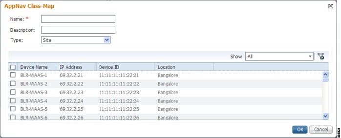
a.![]() From the Show drop-down list, filter the device list as required, quick filter, show all devices, or show all assigned devices.
From the Show drop-down list, filter the device list as required, quick filter, show all devices, or show all assigned devices.
b.![]() Check the box next to each device you want to match traffic from. Check the box next to the column title to select all the devices and uncheck it to deselect all the devices. If any of the selected devices is matched, the class is considered matched.
Check the box next to each device you want to match traffic from. Check the box next to the column title to select all the devices and uncheck it to deselect all the devices. If any of the selected devices is matched, the class is considered matched.
c.![]() Click OK to save the class map and return to the class maps list.
Click OK to save the class map and return to the class maps list.
Step 10![]() (Optional) For a Custom class map type, enter a match condition based on IP address/port or Microsoft RPC application ID, and choose a WAAS peer device. All the specified matching criteria must be met for the class to be considered matched. Perform the following steps to create the class map.
(Optional) For a Custom class map type, enter a match condition based on IP address/port or Microsoft RPC application ID, and choose a WAAS peer device. All the specified matching criteria must be met for the class to be considered matched. Perform the following steps to create the class map.
Figure 4-10 AppNav Class Map with Match Conditions
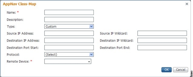
a.![]() Enter values in one or more IP address or port fields, or both, to create a condition for a specific type of traffic. For example, to match all traffic going to ports 5405 to 5407, enter 5405 in the Destination Port Start field and 5407 in the Destination Port End field. You can use the IP address wildcard fields to specify a range of IP addresses using a wildcard subnet mask in dotted decimal notation (such as 0.0.0.255 for /24).
Enter values in one or more IP address or port fields, or both, to create a condition for a specific type of traffic. For example, to match all traffic going to ports 5405 to 5407, enter 5405 in the Destination Port Start field and 5407 in the Destination Port End field. You can use the IP address wildcard fields to specify a range of IP addresses using a wildcard subnet mask in dotted decimal notation (such as 0.0.0.255 for /24).
Note![]() We strongly recommend that you use the Cisco WAAS Central Manager GUI to centrally configure class maps for your Cisco WAAS devices. However, there is one exception to this recommendation. Use the Cisco WAAS CLI to create an AppNav class map with a type of Application or Custom, and whose source or destination address has one of the following: an IP address ending in “0.0.0” or a non-Class A IP address ending in “0.0”.
We strongly recommend that you use the Cisco WAAS Central Manager GUI to centrally configure class maps for your Cisco WAAS devices. However, there is one exception to this recommendation. Use the Cisco WAAS CLI to create an AppNav class map with a type of Application or Custom, and whose source or destination address has one of the following: an IP address ending in “0.0.0” or a non-Class A IP address ending in “0.0”.
b.![]() (Optional) To match Microsoft RPC traffic that uses dynamic port allocation, choose the RPC application identifier from the Protocol drop-down list. For example, to match Microsoft Exchange Server traffic that uses the MAPI protocol, choose mapi.
(Optional) To match Microsoft RPC traffic that uses dynamic port allocation, choose the RPC application identifier from the Protocol drop-down list. For example, to match Microsoft Exchange Server traffic that uses the MAPI protocol, choose mapi.
c.![]() Choose a WAAS peer device from the Remote Device drop-down list.
Choose a WAAS peer device from the Remote Device drop-down list.
d.![]() Click OK to save the class map and return to the class maps configuration window.
Click OK to save the class map and return to the class maps configuration window.
Configuring a Class Map on an AppNav-XE Cluster
To configure a class map on an AppNav-XE cluster, follow these steps:
Step 1![]() From the WAAS Central Manager menu, choose AppNav Clusters > cluster-name.
From the WAAS Central Manager menu, choose AppNav Clusters > cluster-name.
Step 2![]() Choose Configure > AppNav Cluster > AppNav Class-Map.
Choose Configure > AppNav Cluster > AppNav Class-Map.
The AppNav Class-Maps window appears, listing the existing class maps.
From this window, you can perform the following tasks:
- From the Show drop-down list, choose a filter setting to filter the class map list as needed. You can use Quick Filter or Show All Class Maps.
- Edit a class map by selecting it and clicking the Edit taskbar icon.
- Delete one or more class maps by selecting them and clicking the Delete taskbar icon.
- Add a new class map as described in the steps that follow.
Step 3![]() Click the Add Class-Map taskbar icon.
Click the Add Class-Map taskbar icon.
Figure 4-11 AppNav Class Map with Match Condition List
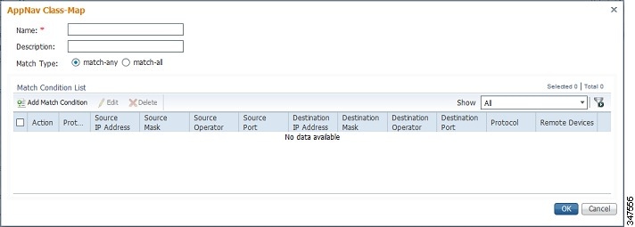
Step 4![]() In the Name field, enter a name for the class map. A maximum of 221 characters, excluding space or question mark (?), can be entered.
In the Name field, enter a name for the class map. A maximum of 221 characters, excluding space or question mark (?), can be entered.
Step 5![]() (Optional) In the Description field, enter a description for the class map. A maximum of 200 characters, excluding a question mark (?), can be entered.
(Optional) In the Description field, enter a description for the class map. A maximum of 200 characters, excluding a question mark (?), can be entered.
Step 6![]() At the Match Type radio buttons, choose match-any or match-all. Match-any means that if any one of the match conditions is matched, the class is considered matched. Match-all means that all the match conditions must be matched for the class to be matched.
At the Match Type radio buttons, choose match-any or match-all. Match-any means that if any one of the match conditions is matched, the class is considered matched. Match-all means that all the match conditions must be matched for the class to be matched.
Step 7![]() Click the Add Match Condition taskbar icon.
Click the Add Match Condition taskbar icon.
The Match Condition pane appears.
Step 8![]() From the Match Condition drop-down list, choose the type of match condition you want to create:
From the Match Condition drop-down list, choose the type of match condition you want to create:
- Source/Destination IP —Matches traffic for a particular application based on an access list of source and/or destination IP addresses and/or ports. Continue with Step 9.
- Protocol —Matches traffic for a particular Microsoft RPC application identifier (for applications that use dynamic port allocation). Continue with Step 10.
- Peer —Matches traffic from particular WAAS peer devices, for site affinity. Continue with Step 11.
- NBAR Protocol—Matches traffic based on application id using the lowest NBAR version protocol pack library that has an evolved application recognition capability. Continue with Step 12.
|
|
|
|---|---|
- Nested Class Maps—Matches traffic from WAAS devices based on multiple traffic classes.Continue with Step 13.
Note![]() If the AppNav cluster runs with more than one router, all the routers software version needs to be greater than or equal to 16.10 for NBAR Protocol or Nested Class Map configuration from the Cisco WAAS Central Manager.
If the AppNav cluster runs with more than one router, all the routers software version needs to be greater than or equal to 16.10 for NBAR Protocol or Nested Class Map configuration from the Cisco WAAS Central Manager.
Note![]() The lowest NBAR protocol version is taken from among all AppNav-XE routers (running software version 16.10 and later) that are registered with the Cisco WAAS Central Manager.
The lowest NBAR protocol version is taken from among all AppNav-XE routers (running software version 16.10 and later) that are registered with the Cisco WAAS Central Manager.
The match conditions shown in the lower part of the pane change depending on the condition type.
Step 9![]() (Optional) For a Source/Destination IP match condition type, enter one or more access control entries (ACEs). You can perform the following tasks in this pane:
(Optional) For a Source/Destination IP match condition type, enter one or more access control entries (ACEs). You can perform the following tasks in this pane:
- Edit an ACE by selecting it and clicking the Edit taskbar icon.
- Delete one or more ACEs by selecting them and clicking the Delete taskbar icon.
- Move one or more selected ACEs to a new position by clicking the Move To taskbar icon. After moving the ACEs, click Save Moved Rows to save the change.
- Move one or more selected ACEs up or down one position by clicking the Up or Down Arrow taskbar icons, and then click Save Moved Rows to save the change.
- Save the ACEs that you have moved with the Move To or Up and Down Arrow functions by clicking the Save Moved Rows taskbar icon.
- Insert a new ACE before the selected row by clicking the Insert taskbar icon. The workflow for inserting is the same as for adding (described in the following steps).
- Add a new ACE, as described in the steps that follow.
a.![]() Click the Add ACE taskbar icon.
Click the Add ACE taskbar icon.
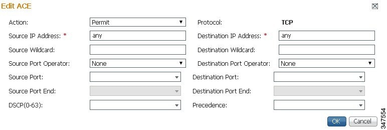
b.![]() From the Action drop-down list, choose Permit or Deny, to determine whether this ACE permits or denies matched traffic.
From the Action drop-down list, choose Permit or Deny, to determine whether this ACE permits or denies matched traffic.
c.![]() Enter values in one or more fields to create an ACE for a specific type of traffic. Enter any in the IP address fields to specify any IP address.
Enter values in one or more fields to create an ACE for a specific type of traffic. Enter any in the IP address fields to specify any IP address.
d.![]() Use the IP address wildcard fields to specify a range of IP addresses using a wildcard subnet mask in dotted decimal notation, for examle, 0.0.0.255 for /24.
Use the IP address wildcard fields to specify a range of IP addresses using a wildcard subnet mask in dotted decimal notation, for examle, 0.0.0.255 for /24.
e.![]() Use the Source/Destination Port Operator drop-down lists to choose an operator and behavior for the port fields:
Use the Source/Destination Port Operator drop-down lists to choose an operator and behavior for the port fields:
–![]() None—Port field is not used.
None—Port field is not used.
–![]() eq—Match requires traffic port to be equal to the Port field.
eq—Match requires traffic port to be equal to the Port field.
–![]() gt—Match requires traffic port to be greater than the Port field.
gt—Match requires traffic port to be greater than the Port field.
–![]() lt—Match requires traffic port to be less than the Port field.
lt—Match requires traffic port to be less than the Port field.
–![]() neq—Match requires traffic port to be not equal to the Port field.
neq—Match requires traffic port to be not equal to the Port field.
–![]() Range—Match requires traffic port to be within the range of ports from the Start Port field through the Port End field.
Range—Match requires traffic port to be within the range of ports from the Start Port field through the Port End field.
In the port fields, you can choose the port from a drop-down list or enter a numeric value.
f.![]() Set the differentiated services code point (DSCP) value. Alternatively, choose a Precedence value from the Precedence drop-down list to set the priority.
Set the differentiated services code point (DSCP) value. Alternatively, choose a Precedence value from the Precedence drop-down list to set the priority.
The DSCP value must be between 0 and 63. Additionally, DSCP names are also allowed.
h.![]() Add additional ACEs. Click OK to save the match condition and return to the Match Conditions list.
Add additional ACEs. Click OK to save the match condition and return to the Match Conditions list.
Step 10![]() (Optional) For a Protocol match condition type, follow these steps:
(Optional) For a Protocol match condition type, follow these steps:
a.![]() From the Select Protocol drop-down list, choose the Microsoft RPC application identifier that identifies the traffic you want to match. For example, to match Microsoft Exchange Server traffic that uses the MAPI protocol, choose mapi.
From the Select Protocol drop-down list, choose the Microsoft RPC application identifier that identifies the traffic you want to match. For example, to match Microsoft Exchange Server traffic that uses the MAPI protocol, choose mapi.
b.![]() Click OK to save the match condition and return to the match conditions list.
Click OK to save the match condition and return to the match conditions list.
Step 11![]() (Optional) For a Peer match condition type, select one or more peer devices. Follow these steps to create the match condition:
(Optional) For a Peer match condition type, select one or more peer devices. Follow these steps to create the match condition:
a.![]() From the Show drop-down list, choose a filter to filter the device list as needed. You can use Quick Filter, Show All Devices, or Show All Assigned Devices.
From the Show drop-down list, choose a filter to filter the device list as needed. You can use Quick Filter, Show All Devices, or Show All Assigned Devices.
b.![]() Check the check box next to each device you want to match traffic from. You can check the check box next to the column title to select all the devices and uncheck it to deselect all devices.
Check the check box next to each device you want to match traffic from. You can check the check box next to the column title to select all the devices and uncheck it to deselect all devices.
c.![]() Click OK to save the match condition and return to the match conditions list.
Click OK to save the match condition and return to the match conditions list.
Step 12![]() (Optional) For a NBAR Protocol match condition type, follow these steps:
(Optional) For a NBAR Protocol match condition type, follow these steps:
a.![]() From the NBAR Protocol Type drop-down list, choose Protocol.
From the NBAR Protocol Type drop-down list, choose Protocol.
–![]() Select the NBAR Protocol from the drop-down list to match traffic based on the protocol. Note that when you use the Cisco WAAS Central Manager to create a class map and match condition with the NBAR protocol, you can match condition to the protocol on the router running only the lowest NBAR version protocol pack.
Select the NBAR Protocol from the drop-down list to match traffic based on the protocol. Note that when you use the Cisco WAAS Central Manager to create a class map and match condition with the NBAR protocol, you can match condition to the protocol on the router running only the lowest NBAR version protocol pack.
- After you create a class map from the Cisco WAAS Central Manager, if you use the Cisco WAAS CLI to create a class map and match condition with the router that has the greater NBAR protocols, the Cisco WAAS Central Manager page detects a configuration conflict and the device goes into the Force Device Settings (FDG) mode.
- When the router version is upgraded or downgraded from the Cisco WAAS CLI, and if the router does not support the NBAR Protocol, the devices configured with the class map to use the NBAR match condition protocol go into the FDG mode as there is a configuration conflict.
- When the Cisco WAAS Central Manager is downgraded to a version that does not support NBAR Protocol or nested class maps, an error message guides you to remove the App ID configuration before downgrading the Cisco WAAS Central Manager.
–![]() Select the NBAR Attribute and the NBAR Sub-Attribute from the respective drop-down to set the traffic to match the Attribute. Attributes feature provides the mechanism to match applications based on certain attributes. This helps with performing group actions on them. Attributes are statically assigned to each protocol or application, and they are not dependent on the traffic.
Select the NBAR Attribute and the NBAR Sub-Attribute from the respective drop-down to set the traffic to match the Attribute. Attributes feature provides the mechanism to match applications based on certain attributes. This helps with performing group actions on them. Attributes are statically assigned to each protocol or application, and they are not dependent on the traffic.
The data is visible in the Match Condition List table.
b.![]() Click OK to save the class map and return to the Class Maps Configuration window.
Click OK to save the class map and return to the Class Maps Configuration window.
Step 13![]() (Optional) For a Nested Class Map match condition type, follow these steps:
(Optional) For a Nested Class Map match condition type, follow these steps:
a.![]() Select the Nested Class Maps drop-down list and click OK. All the existing class maps from the Cisco WAAS Central Manager database are listed in the AppNav Class-Map drop down list.
Select the Nested Class Maps drop-down list and click OK. All the existing class maps from the Cisco WAAS Central Manager database are listed in the AppNav Class-Map drop down list.
b.![]() Select the class map and click OK.
Select the class map and click OK.
An entry is created in the first dialog box, i.e, the AppNav Class Map dialog box. Consider the following guidelines for nested class maps:
–![]() You can nest up to two levels from the Cisco WAAS Central Manager. Any further configuration from the Cisco WAAS Central Manager shows a warning.
You can nest up to two levels from the Cisco WAAS Central Manager. Any further configuration from the Cisco WAAS Central Manager shows a warning.
–![]() Although you can use the Cisco WAAS CLI for this configuration, we recommend that you do not configure more than two layers from the Cisco WAAS CLI, because the configurations are incorrect.
Although you can use the Cisco WAAS CLI for this configuration, we recommend that you do not configure more than two layers from the Cisco WAAS CLI, because the configurations are incorrect.
Step 14![]() Click OK to save the class map and return to the Class Maps Configuration window.
Click OK to save the class map and return to the Class Maps Configuration window.
Configuring Rules Within an AppNav Policy
Configuring AppNav Policy Rules on a Cisco WAAS Appliance AppNav Cluster
To configure AppNav policy rules on a Cisco WAAS appliance AppNav cluster, follow these steps:
Step 1![]() From the Cisco WAAS Central Manager menu, choose AppNav Clusters > cluster-name.
From the Cisco WAAS Central Manager menu, choose AppNav Clusters > cluster-name.
Step 2![]() Choose Configure > AppNav Cluster > AppNav Policies.
Choose Configure > AppNav Cluster > AppNav Policies.
The AppNav Policy window appears.
Step 3![]() Choose the policy to configure from the AppNav Policy drop-down list at the top.
Choose the policy to configure from the AppNav Policy drop-down list at the top.
You can click Manage to create or delete a policy or configure the ANCs to which a policy is applied. For details see Managing Cisco WAAS Appliance Policies.
From the AppNav Policy Rules area, you can perform the following tasks:
- From the Show drop-down list, choose the filter to filter the rule list as needed. You can use a Quick Filter or Show All Rules.
- Edit a rule by selecting it and clicking the Edit taskbar icon.
- Delete one or more rules by selecting them and clicking the Delete taskbar icon.
- Move one or more selected rules to a new position by clicking the Move To taskbar icon. After moving the rows, click Save Moved Rows to save the change.
- Move one or more selected rules up or down one position by clicking the Up or Down Arrow taskbar icons, and then click Save Moved Rows to save the change.
- Insert a new rule before the selected row by clicking the Insert taskbar icon. The workflow for inserting is the same as for adding (described in the following steps).
- Add a new rule at the end of the list, as described in the following steps. (The class default rule is always pushed to the last position.)
Step 4![]() Click the Add Policy Rule taskbar icon.
Click the Add Policy Rule taskbar icon.
Figure 4-13 AppNav Policy Rule Pane
Step 5![]() From the AppNav Class-Map drop-down list, choose the class map to which this policy rule applies.
From the AppNav Class-Map drop-down list, choose the class map to which this policy rule applies.
To edit the class map, click Edit. To create a new class map, click Create New. The workflow is the same, as described in Configuring a Cisco WAAS Appliance AppNav Class Map.
Step 6![]() From the Distribute To drop-down list, choose the distribution action to apply to the class map. The list includes all the defined WNGs and the associated options: None, for no action, and Passthrough, to pass through this type of traffic. The definition of None is context-dependent: in a top-level policy it means pass-through, if this policy is nested, it means inherit the parent policy rule action.
From the Distribute To drop-down list, choose the distribution action to apply to the class map. The list includes all the defined WNGs and the associated options: None, for no action, and Passthrough, to pass through this type of traffic. The definition of None is context-dependent: in a top-level policy it means pass-through, if this policy is nested, it means inherit the parent policy rule action.
a.![]() When you choose a WNG, other settings appear.
When you choose a WNG, other settings appear.
b.![]() To create a new WNG, click Create New.
To create a new WNG, click Create New.
–![]() The workflow is the same as that described in Adding a New WAAS Node Group to the Cluster.
The workflow is the same as that described in Adding a New WAAS Node Group to the Cluster.
–![]() The newly created WNG appears in both the Distribute To and Backup drop-down lists.
The newly created WNG appears in both the Distribute To and Backup drop-down lists.
Step 7![]() (Optional) From the Backup drop-down list, choose the backup WNG to use for distribution if the primary WNG is unavailable.
(Optional) From the Backup drop-down list, choose the backup WNG to use for distribution if the primary WNG is unavailable.
Step 8![]() (Optional) From the Monitor drop-down list, choose the application accelerator to monitor. When you monitor an application accelerator, the ANC checks for overload on that application accelerator and does not send new flows to a WAAS node that is overloaded. If you choose None, a specific application accelerator is not monitored, only the maximum connection limit of the device is monitored.
(Optional) From the Monitor drop-down list, choose the application accelerator to monitor. When you monitor an application accelerator, the ANC checks for overload on that application accelerator and does not send new flows to a WAAS node that is overloaded. If you choose None, a specific application accelerator is not monitored, only the maximum connection limit of the device is monitored.
Step 9![]() (Optional) To apply a nested policy within this rule, click Nested Actions (Advanced) to expand this area.
(Optional) To apply a nested policy within this rule, click Nested Actions (Advanced) to expand this area.
Step 10![]() (Optional) From the Nested Policy drop-down list, choose the policy to nest, or choose None to select no policy. When you choose a policy, the policy rules are displayed in a table.
(Optional) From the Nested Policy drop-down list, choose the policy to nest, or choose None to select no policy. When you choose a policy, the policy rules are displayed in a table.
If there are policies that are ineligible to be specified as a nested policy, click Show Ineligible Policies to display them and the reasons they are ineligible. A policy is ineligible if it already has a nested policy, because only one level of nesting is allowed.
To edit the chosen policy, click Edit. To create a new policy for nesting, click Create New. The workflow for both editing and creating is the same.
a.![]() In the Name field, enter the policy name.
In the Name field, enter the policy name.
Note![]() This field is not editable for the waas_app_default policy.
This field is not editable for the waas_app_default policy.
b.![]() Click the Add Policy Rule taskbar icon.
Click the Add Policy Rule taskbar icon.
A new row is added, showing fields for configuring the rule.
c.![]() From the Class-Map drop-down list, choose the class map to which this rule applies.
From the Class-Map drop-down list, choose the class map to which this rule applies.
d.![]() From the Distribute To drop-down list, choose the distribution action to apply to the class map. The list includes all the defined WNGs and the choices, Inherit, to inherit this action from the parent policy, and Passthrough, to pass through this type of traffic.
From the Distribute To drop-down list, choose the distribution action to apply to the class map. The list includes all the defined WNGs and the choices, Inherit, to inherit this action from the parent policy, and Passthrough, to pass through this type of traffic.
e.![]() (Optional) From the Backup drop-down list, choose the backup WNG to use for distribution if the primary WNG is unavailable.
(Optional) From the Backup drop-down list, choose the backup WNG to use for distribution if the primary WNG is unavailable.
f.![]() (Optional) From the Monitor drop-down list, choose the application accelerator to monitor.
(Optional) From the Monitor drop-down list, choose the application accelerator to monitor.
g.![]() Click OK to save the policy rule and return to the AppNav Policy Rule pane for the primary policy rule you are creating.
Click OK to save the policy rule and return to the AppNav Policy Rule pane for the primary policy rule you are creating.
Step 11![]() Click OK to create the policy rule and return to the Policy Configuration window.
Click OK to create the policy rule and return to the Policy Configuration window.
Note![]() If all the AppNav policies have been deleted and you add a new policy rule, the policy rule is added to a new appnav_default policy, which is created automatically.
If all the AppNav policies have been deleted and you add a new policy rule, the policy rule is added to a new appnav_default policy, which is created automatically.
Configuring AppNav-XE Policy Rules on an AppNav-XE Cluster
To configure AppNav policy rules on an AppNav-XE cluster, follow these steps:
Step 1![]() From the Cisco WAAS Central Manager menu, choose AppNav Clusters > cluster-name.
From the Cisco WAAS Central Manager menu, choose AppNav Clusters > cluster-name.
Step 2![]() Choose Configure > AppNav Cluster > AppNav Policies.
Choose Configure > AppNav Cluster > AppNav Policies.
The AppNav Policy window appears.
Step 3![]() Click the radio button next to the policy you want to configure in the AppNav Policies table at the top of the window.
Click the radio button next to the policy you want to configure in the AppNav Policies table at the top of the window.
In the AppNav Policies table, you can perform the following tasks:
- Use the filter settings in the Show drop-down list to filter the rule list as needed. You can use Quick Filter or Show All Rules.
- Edit a policy by selecting it and clicking the Edit taskbar icon.
- Delete a policy by selecting it and clicking the Delete taskbar icon.
- Unassign a policy by selecting it and clicking the Unassign Policy taskbar icon.
- Add a policy by clicking the Add Policy taskbar icon.
For details on these tasks see Managing AppNav-XE Policies.
The AppNav Policy Rules table in the lower part of the window shows the selected rules in the AppNav Policies table. From this table, you can perform the following tasks:
- From the Show drop-down list, choose a filter to filter the rule list as needed. You can use Quick Filter or Show All Rules.
- Edit a rule by selecting it and clicking the Edit taskbar icon.
- Delete one or more rules by selecting them and clicking the Delete taskbar icon.
- Move one or more selected rules to a new position by clicking the Move To taskbar icon. After moving the rows, click Save Moved Rows to save the change.
- Move one or more selected rules up or down one position by clicking the Up or Down Arrow taskbar icons, and then click Save Moved Rows to save the change.
- Insert a new rule before the selected row by clicking the Insert taskbar icon. The workflow for inserting is the same as for adding (described in the following steps).
- Add a new rule at the end of the list, as described in the steps that follow. (The class default rule is always pushed to the last position.)
Step 4![]() Click the Add Policy Rule taskbar icon.
Click the Add Policy Rule taskbar icon.
Figure 4-14 AppNav Policy Rule Pane
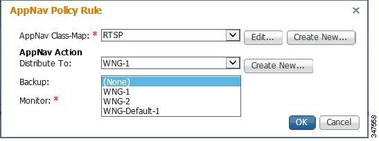
Step 5![]() From the AppNav Class-Map drop-down list, choose the class map to which this policy rule applies.
From the AppNav Class-Map drop-down list, choose the class map to which this policy rule applies.
The workflow is the same as described in Configuring a Class Map on an AppNav-XE Cluster.
Step 6![]() From the Distribute To drop-down list, choose the distribution action to apply to the class map. The list includes WNGs and the choices None, for no action, and Passthrough, to pass through this type of traffic. Here, the meaning of None is the same as Passthrough. For the default policy map, the WNG list includes the default WNG and any custom WNG that is a part of the assigned context. For a custom policy map, the WNG list includes default and custom WNGs that are not already assigned to another context.
From the Distribute To drop-down list, choose the distribution action to apply to the class map. The list includes WNGs and the choices None, for no action, and Passthrough, to pass through this type of traffic. Here, the meaning of None is the same as Passthrough. For the default policy map, the WNG list includes the default WNG and any custom WNG that is a part of the assigned context. For a custom policy map, the WNG list includes default and custom WNGs that are not already assigned to another context.
When you choose a WNG, other settings appear. To create a new WNG, click Create New. The workflow is the same as described in Adding a New WAAS Node Group to the Cluster. The newly created WNG appears in the Distribute To drop-down list.
Step 7![]() (Optional) From the Backup drop-down list, choose the backup WNG to use for distribution if the primary WNG is unavailable or overloaded.
(Optional) From the Backup drop-down list, choose the backup WNG to use for distribution if the primary WNG is unavailable or overloaded.
Consider the following operating guidelines for the backup WNG:
- The Backup WNG option is available only for cluster/s that have XE3.13 devices or later.
It is recommended that prior to downgrading the Cisco WAAS Central Manager to a release up to 5.2.1, the Backup WNG must be removed from the AppNav-XE cluster and make sure Cisco WAAS Central Manager and AppNav-XE device configuration is in sync. - PreXE3.13 controllers cannot be added to the cluster policy that has been configured with a backup WNG. A validation message is displayed while adding preXE3.13 controller to a cluster with backup WNG policy.
A cluster having PreXE3.13 devices cannot be configured with backup WNG. The option for backup WNG will not be visible if the cluster has at least one pre-3.13 XE device.
Step 8![]() (Optional) From the Monitor drop-down list, choose the application accelerator to monitor. When you monitor an application accelerator, the ANC checks for overload on that application accelerator and does not send new flows to a WAAS node that is overloaded. If you choose None, a specific application accelerator is not monitored, only the maximum connection limit of the device is monitored.
(Optional) From the Monitor drop-down list, choose the application accelerator to monitor. When you monitor an application accelerator, the ANC checks for overload on that application accelerator and does not send new flows to a WAAS node that is overloaded. If you choose None, a specific application accelerator is not monitored, only the maximum connection limit of the device is monitored.
Step 9![]() Click OK to create the policy rule and return to the policy configuration window.
Click OK to create the policy rule and return to the policy configuration window.
Managing AppNav Policies
Managing Cisco WAAS Appliance Policies
To create or delete AppNav policies or configure the ANCs to which policies apply in a WAAS appliance AppNav cluster, follow these steps:
Step 1![]() From the WAAS Central Manager menu, choose AppNav Clusters > cluster-name.
From the WAAS Central Manager menu, choose AppNav Clusters > cluster-name.
Step 2![]() Choose Configure > AppNav Cluster > AppNav Policies.
Choose Configure > AppNav Cluster > AppNav Policies.
The AppNav Policy window appears.
Step 3![]() Choose the policy to view from the AppNav Policy drop-down list at the top.
Choose the policy to view from the AppNav Policy drop-down list at the top.
For details on using the AppNav Policy Rules area see Configuring AppNav Policy Rules on a Cisco WAAS Appliance AppNav Cluster.
Figure 4-15 Manage AppNav Policies Pane
From the Manage AppNav Policies pane, you can perform the following tasks:
- From the Show drop-down list, choose a filter to filter the policy list as needed. You can use a Quick Filter or Show All Policies.
- Edit a policy and configure the ANCs to which it applies by selecting it and clicking the Edit taskbar icon.
- Delete a policy by selecting it and clicking the Delete taskbar icon.
- Add a new policy, as described in the following steps.
Step 5![]() Click the Add Policy taskbar icon.
Click the Add Policy taskbar icon.
Figure 4-16 AppNav Policy Pane
Step 6![]() In the Name field, enter a name for the policy. A maximum of 40 alphanumeric characters, including an underscore, can be entered.
In the Name field, enter a name for the policy. A maximum of 40 alphanumeric characters, including an underscore, can be entered.
Step 7![]() (Optional) In the Description field, enter a description for the policy. A maximum of 200 alphanumeric characters, including underscore and space, can be entered.
(Optional) In the Description field, enter a description for the policy. A maximum of 200 alphanumeric characters, including underscore and space, can be entered.
Step 8![]() (Optional) Check the check box next to each ANC that you want to assign to this policy. To unassign any assigned devices, uncheck the check box.
(Optional) Check the check box next to each ANC that you want to assign to this policy. To unassign any assigned devices, uncheck the check box.
Assigning a policy to an ANC makes the policy active on that ANC (only one policy can be active on an ANC) and removes the association of any previously active policy on that ANC. It is not necessary to assign a policy to an ANC if you want to create the policy as an alternative. You can assign it to ANCs later, as required.
Step 9![]() Click OK to save the policy and return to the Manage AppNav Policies pane.
Click OK to save the policy and return to the Manage AppNav Policies pane.
Step 10![]() Click Close to return to the Policy Configuration window.
Click Close to return to the Policy Configuration window.
Step 11![]() Add policy rules to the new policy as described in Configuring AppNav Policy Rules on a Cisco WAAS Appliance AppNav Cluster.
Add policy rules to the new policy as described in Configuring AppNav Policy Rules on a Cisco WAAS Appliance AppNav Cluster.
To restore the default class maps and policy maps to your cluster, click the Restore Default taskbar icon at the top of the AppNav Policies window. This action removes all the existing class and policy map configurations and restores the default class and policy maps. All the WAAS nodes assigned to WNGs are moved to the default WNG, and other WNGs are removed.
Managing AppNav-XE Policies
To create or delete AppNav policies or unassign a policy from a context in an AppNav-XE cluster, follow these steps:
Step 1![]() From the Cisco WAAS Central Manager menu, choose AppNav Clusters > cluster-name.
From the Cisco WAAS Central Manager menu, choose AppNav Clusters > cluster-name.
Step 2![]() Choose Configure > AppNav Cluster > AppNav Policies.
Choose Configure > AppNav Cluster > AppNav Policies.
The AppNav Policy window appears.
Step 3![]() Click the radio button next to the policy to modify, in the AppNav Policies table at the top of the window.
Click the radio button next to the policy to modify, in the AppNav Policies table at the top of the window.
From the AppNav Policies table, you can perform the following tasks:
- From the Show drop-down list, choose a filter to the rule list as required. You can use Quick Filter or Show All Rules.
- Edit a policy by selecting it and clicking the Edit taskbar icon.
- Delete a policy by selecting it and clicking the Delete taskbar icon.
- Unassign a policy from a context by selecting it and clicking the Unassign Policy taskbar icon. Unassigning a policy from a context also disables the context and unassigns all the WNGs from the context. Click OK again to confirm that you want to proceed.
- Add a new policy, as described in the steps that follow.
For details on using the AppNav Policy Rules area, see Configuring AppNav-XE Policy Rules on an AppNav-XE Cluster.
Step 4![]() Click the Add Policy taskbar icon.
Click the Add Policy taskbar icon.
Figure 4-17 AppNav Policy Pane
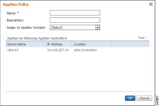
Step 5![]() In the Name field enter a name for the policy. A maximum of up to 227 characters, excluding a space or question mark (?), can be entered. Do not use a name of the format APPNAV- n -PMAP, which is used for default policy maps.
In the Name field enter a name for the policy. A maximum of up to 227 characters, excluding a space or question mark (?), can be entered. Do not use a name of the format APPNAV- n -PMAP, which is used for default policy maps.
Step 6![]() (Optional) In the Description field, enter a description for the policy. A maximum of up to 200 characters, not including a question mark (?), can be entered.
(Optional) In the Description field, enter a description for the policy. A maximum of up to 200 characters, not including a question mark (?), can be entered.
Step 7![]() From the Assign to AppNav Context drop-down list, choose the context to which to assign the new policy.
From the Assign to AppNav Context drop-down list, choose the context to which to assign the new policy.
Assigning the policy to a context makes the policy active on all the ANCs that are a part of the context. Only contexts that do not already have an assigned policy are listed.
For default policy maps, only one context is displayed, based on the context ID. For example, for APPNAV-4-PMAP, only waas/4 is displayed (in case it is not already assigned).
Step 8![]() Click OK to save the policy and return to the AppNav Policies window.
Click OK to save the policy and return to the AppNav Policies window.
Step 9![]() Add policy rules to the new policy as described in Configuring AppNav-XE Policy Rules on an AppNav-XE Cluster.
Add policy rules to the new policy as described in Configuring AppNav-XE Policy Rules on an AppNav-XE Cluster.
To restore the default class maps and policy maps to your cluster, click the Restore Default taskbar icon at the top of the AppNav Policies window. This action removes all the existing class and policy map configurations and restores the default class and policy maps. All the WAAS nodes assigned to each context are moved to their respective default WNGs and all the unassigned WNGs are removed.
Configuring Cisco WAAS Node Optimization Policy
The WAAS node optimization policy controls how traffic that is distributed to the WAAS nodes is optimized. The optimization policy is configured on the WAAS nodes and the ANCs that are also acting as optimizing nodes.
All the WAAS nodes in one WNG must have an identical optimization policy configured on them. Otherwise, optimization of flows is not predictable. The optimization policy can be different for different WNGs.
For information on how to configure the optimization policy, see “Configuring Application Acceleration” .
The default optimization policy is listed in Appendix A, “Predefined Optimization Policy.”
Configuring AppNav Controller ACLs
An AppNav Controller ACL controls what traffic is intercepted by a Cisco WAAS appliance ANC. You may want to configure an ANC interception ACL for each Cisco WAAS appliance ANC in an AppNav Cluster.
For information on how to configure an ANC interception ACL, see Configuring Interception Access Control Lists in the chapter “Configuring Traffic Interception” .
Configuring AppNav Cluster Settings
To configure AppNav Cluster settings for an AppNav cluster, follow these steps:
Step 1![]() From the Cisco WAAS Central Manager menu, choose AppNav Clusters > All AppNav Clusters.
From the Cisco WAAS Central Manager menu, choose AppNav Clusters > All AppNav Clusters.
The Manage AppNav Clusters window showing the status of each cluster appears.
From this window, you can perform the following tasks:
- Create a new AppNav Cluster. The workflow is the same as described in Creating a New AppNav Cluster with the AppNav Cluster Wizard.
- Delete an AppNav Cluster by selecting an AppNav Cluster and clicking the Delete icon in the taskbar of the Manage AppNav Clusters area.
- View an AppNav Cluster topology and edit its settings as described in the following steps:
Step 2![]() Click the name of the cluster whose settings you want to edit.
Click the name of the cluster whose settings you want to edit.
The cluster topology diagram appears.
Step 3![]() Choose Configure > AppNav Cluster > AppNav Cluster.
Choose Configure > AppNav Cluster > AppNav Cluster.
The Cluster Configuration window appears.
Figure 4-18 Cluster Configuration Window
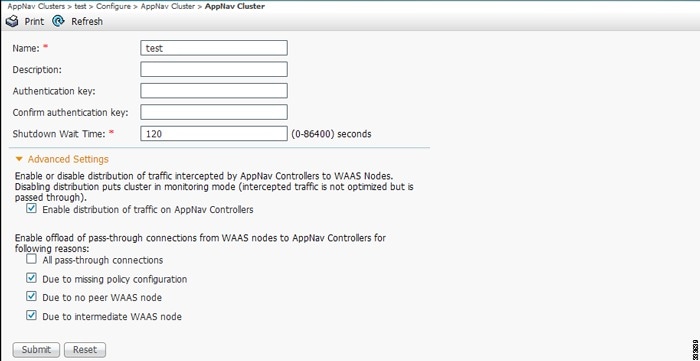
Step 4![]() In the Name field, enter a new name for the cluster if you want to rename it. (This feature is not available on AppNav-XE clusters.)
In the Name field, enter a new name for the cluster if you want to rename it. (This feature is not available on AppNav-XE clusters.)
Step 5![]() (Optional) In the Description field, enter the cluster description. Use only letters and numbers, up to a maximum of 200 characters. (This feature is not available on AppNav-XE clusters.)
(Optional) In the Description field, enter the cluster description. Use only letters and numbers, up to a maximum of 200 characters. (This feature is not available on AppNav-XE clusters.)
Step 6![]() (Optional) In the Authentication Key and Confirm Authentication Key fields, enter an authentication key that is used to authenticate communications between the Cisco WAAS devices in the cluster. Use only letters and numbers, up to a maximum of 64 characters.
(Optional) In the Authentication Key and Confirm Authentication Key fields, enter an authentication key that is used to authenticate communications between the Cisco WAAS devices in the cluster. Use only letters and numbers, up to a maximum of 64 characters.
Step 7![]() (Optional) In the Shutdown Wait Time field, enter the number of seconds that the WAAS nodes in the cluster should wait for all the connections to get terminated before shutting down. The default is 120 seconds.
(Optional) In the Shutdown Wait Time field, enter the number of seconds that the WAAS nodes in the cluster should wait for all the connections to get terminated before shutting down. The default is 120 seconds.
Step 8![]() (Optional) To configure cluster distribution and off-loading of pass-through connections, expand the Advanced Settings section by clicking it.
(Optional) To configure cluster distribution and off-loading of pass-through connections, expand the Advanced Settings section by clicking it.
Step 9![]() (Optional) To enable distribution of traffic from the ANCs in the cluster to WAAS nodes, ensure that the Enable distribution of traffic on AppNav Controllers check box is checked. To disable distribution of traffic, uncheck this box. When distribution is disabled, the cluster operates in monitoring mode where it continues to intercept traffic and, instead of distributing it to WAAS nodes, passes it through. This mode can be useful for monitoring traffic statistics without optimizing the traffic. (Not available on AppNav-XE clusters.)
(Optional) To enable distribution of traffic from the ANCs in the cluster to WAAS nodes, ensure that the Enable distribution of traffic on AppNav Controllers check box is checked. To disable distribution of traffic, uncheck this box. When distribution is disabled, the cluster operates in monitoring mode where it continues to intercept traffic and, instead of distributing it to WAAS nodes, passes it through. This mode can be useful for monitoring traffic statistics without optimizing the traffic. (Not available on AppNav-XE clusters.)
Step 10![]() (Optional) To configure offloading of pass-through connections from WAAS nodes to ANCs, check the check boxes in the Enable offload of pass-through connections from WAAS nodes to AppNav Controllers for following reasons section. This feature allows pass-through connections to be passed through at the ANC instead of being distributed to the WAAS node and then passed through. Configure pass-through offload as follows:
(Optional) To configure offloading of pass-through connections from WAAS nodes to ANCs, check the check boxes in the Enable offload of pass-through connections from WAAS nodes to AppNav Controllers for following reasons section. This feature allows pass-through connections to be passed through at the ANC instead of being distributed to the WAAS node and then passed through. Configure pass-through offload as follows:
a.![]() To offload all pass-through connections, which includes connections passed through due to error conditions, check the All pass-through connections check box. Check this check box only if you do not require application visibility on the WNs into pass-through traffic due to error conditions. The default is unchecked.
To offload all pass-through connections, which includes connections passed through due to error conditions, check the All pass-through connections check box. Check this check box only if you do not require application visibility on the WNs into pass-through traffic due to error conditions. The default is unchecked.
b.![]() To offload connections passed through due to missing policy configuration, check the Due to missing policy configuration check box. By default, it is checked.
To offload connections passed through due to missing policy configuration, check the Due to missing policy configuration check box. By default, it is checked.
c.![]() To offload connections passed through due to the absence of peer WAAS node, check the Due to no peer WAAS node check box. By default, it is checked.
To offload connections passed through due to the absence of peer WAAS node, check the Due to no peer WAAS node check box. By default, it is checked.
d.![]() To offload connections passed through due to an intermediate WAAS node, check the Due to intermediate WAAS node check box. By default, it is checked.
To offload connections passed through due to an intermediate WAAS node, check the Due to intermediate WAAS node check box. By default, it is checked.
e.![]() If some of the WAAS nodes use different pass-through offload settings, you can synchronize the settings on all the WAAS nodes to match the configuration shown here by checking the Synchronize settings on all devices check box. This check box is shown only if the settings on some WAAS nodes are different. The default is unchecked.
If some of the WAAS nodes use different pass-through offload settings, you can synchronize the settings on all the WAAS nodes to match the configuration shown here by checking the Synchronize settings on all devices check box. This check box is shown only if the settings on some WAAS nodes are different. The default is unchecked.
The lower part of this window includes tabs that show lists of the ANCs, WAAS nodes, and WNGs that are a part of the cluster. On AppNav-XE devices, there is an additional AppNav Contexts tab that displays contexts. The controls in these parts of this window work as described in the following sections:
- AppNav Controllers: Configuring AppNav Controller Settings
- AppNav Contexts: Configuring AppNav Contexts
- WAAS Nodes: Configuring WAAS Node Settings
- WAAS Node Groups: Configuring Cisco WAAS Node Group Settings
To configure AppNav Cluster settings for an individual WAAS node, see ConfiguringCisco AppNav Cluster Settings for a Cisco WAAS Node. If you are using an authentication key to authenticate communications, you must configure the cluster and each WAAS node with the same key.
Configuring AppNav Controller Settings
Configuring AppNav Controller Settings for a Cisco WAAS Appliance
To configure ANC settings for a WAAS appliance, follow these steps:
Step 1![]() From the Cisco WAAS Central Manager menu, choose AppNav Clusters > cluster-name.
From the Cisco WAAS Central Manager menu, choose AppNav Clusters > cluster-name.
Step 2![]() Click the AppNav Controllers tab below the topology diagram.
Click the AppNav Controllers tab below the topology diagram.
All the ANCs in the cluster are listed, along with the name, location, IP address, and interface used for intracluster traffic, and enabled status.
From this list, you can perform the following tasks:
- Edit the interface settings for an ANC by choosing the ANC and clicking the Edit taskbar icon, as described in Step 3 through Step 7.
- Delete an ANC by choosing the ANC and clicking the Delete taskbar icon.
- Add a new ANC to the cluster by clicking the Add AppNav Controller taskbar icon. See Adding an ANC to a Cluster.
- Enable a disabled ANC by choosing the cluster and clicking the Enable taskbar icon.
- Disable an ANC by choosing the ANC and clicking the Disable taskbar icon.
Step 3![]() Click the radio button next to the ANC that you want to edit and click the Edit taskbar icon.
Click the radio button next to the ANC that you want to edit and click the Edit taskbar icon.
The Edit AppNav Controller pane appears.
Step 4![]() Configure the internal Cisco WAAS node settings:
Configure the internal Cisco WAAS node settings:
a.![]() To enable optimization on the ANC, check the Enable WAN optimization (Internal WAAS Node) check box.
To enable optimization on the ANC, check the Enable WAN optimization (Internal WAAS Node) check box.
b.![]() If you enabled WAN optimization, from the WAAS Node Group drop-down list, choose the WNG to which the internal WAAS node should belong.
If you enabled WAN optimization, from the WAAS Node Group drop-down list, choose the WNG to which the internal WAAS node should belong.
Step 5![]() (Optional) Configure the WCCP settings for the ANC. This window does not appear if the ANC is configured for inline interception. For more information on the WCCP fields, see the Configuring or Viewing the WCCP Settings on ANCs in the chapter “Configuring Traffic Interception” .
(Optional) Configure the WCCP settings for the ANC. This window does not appear if the ANC is configured for inline interception. For more information on the WCCP fields, see the Configuring or Viewing the WCCP Settings on ANCs in the chapter “Configuring Traffic Interception” .
When finished with the WCCP settings, click Next.
The graphical interface wizard appears.
Step 6![]() Configure the interception and cluster interface settings:
Configure the interception and cluster interface settings:
a.![]() In the graphical interface view, configure interception interfaces on the AppNav Controller Interface Module, as required. For details on how to use the wizard, see Configuring Interfaces with the Graphical Interface Wizard.
In the graphical interface view, configure interception interfaces on the AppNav Controller Interface Module, as required. For details on how to use the wizard, see Configuring Interfaces with the Graphical Interface Wizard.
b.![]() From the Cluster Interface drop-down list, choose the interface to be used for intracluster traffic.
From the Cluster Interface drop-down list, choose the interface to be used for intracluster traffic.
c.![]() (Optional) To enable swapping of client and Cisco WAAS device source IP address fields in intra-cluster traffic, check the Enable swapping of source IP address in intra-cluster traffic check box.
(Optional) To enable swapping of client and Cisco WAAS device source IP address fields in intra-cluster traffic, check the Enable swapping of source IP address in intra-cluster traffic check box.
You may want to enable this option if you are using a port channel for the cluster interface or there is a load-balancing device between the ANC and WAAS node. This option can improve the load balancing of the traffic that the ANC distributes to WNs for optimization because it load balances based on the client IP address rather than the ANC IP address. (For traffic from the server to the client, it swaps the server IP address with the ANC IP address.) The Cisco WAAS Central Manager enables this feature automatically if any existing ANCs have port channel cluster interfaces.
Configuring ANC Settings for an AppNav-XE Device
To configure ANC settings for an AppNav-XE device, follow these steps:
Step 1![]() From the Cisco WAAS Central Manager menu, choose AppNav Clusters > cluster-name.
From the Cisco WAAS Central Manager menu, choose AppNav Clusters > cluster-name.
Step 2![]() Click the AppNav Controllers tab below the topology diagram.
Click the AppNav Controllers tab below the topology diagram.
All the ANCs in the cluster are listed, along with the name, location, IP address, interface used for intracluster traffic, and enabled status.
From this list, you can perform the following tasks:
- Edit the interface settings for an ANC by choosing the ANC and clicking the Edit taskbar icon, as described in the following steps.
- Delete an ANC by choosing the ANC and clicking the Delete taskbar icon.
- Add a new ANC to the cluster by clicking the Add AppNav Controller taskbar icon. See Adding an ANC to a Cluster.
Step 3![]() Click the radio button next to the ANC that you want to edit and click the Edit taskbar icon.
Click the radio button next to the ANC that you want to edit and click the Edit taskbar icon.
The Edit AppNav Controller pane appears.
Step 4![]() On an AppNav-XE cluster, configure the interception and cluster interface settings:
On an AppNav-XE cluster, configure the interception and cluster interface settings:
a.![]() Choose the WAN interfaces on which traffic interception is to be enabled. Interfaces must already be configured on the AppNav-XE devices; only those on which service insertion can be enabled are listed.
Choose the WAN interfaces on which traffic interception is to be enabled. Interfaces must already be configured on the AppNav-XE devices; only those on which service insertion can be enabled are listed.
b.![]() From the Cluster Interface drop-down list, choose the interface to be used for intra-cluster traffic.
From the Cluster Interface drop-down list, choose the interface to be used for intra-cluster traffic.
Configuring AppNav Contexts
An AppNav-XE cluster can have up to 32 contexts. A WAAS appliance AppNav cluster can have only one context, which is defined by the cluster settings; the ability to add contexts is not available.
To configure AppNav contexts, follow these steps:
Step 1![]() From the Cisco WAAS Central Manager menu, choose AppNav Clusters > cluster-name.
From the Cisco WAAS Central Manager menu, choose AppNav Clusters > cluster-name.
Step 2![]() Click the AppNav Contexts tab below the topology diagram.
Click the AppNav Contexts tab below the topology diagram.
All the AppNav contexts in the cluster are listed, along with the name, associated WNGs, VRFs, the AppNav policy, and enabled status.
From this list, you can perform the following tasks:
- Edit a context by choosing the context and clicking the Edit taskbar icon.
- Delete a context by choosing the context and clicking the Delete taskbar icon.
- Enable a disabled context by choosing the context and clicking the Enable taskbar icon.
- Disable a context by choosing the context and clicking the Disable taskbar icon.
- Add a new context as described in the steps that follow. (This feature is not allowed for WAAS appliance clusters.)
Step 3![]() Click the Add AppNav Context taskbar icon.
Click the Add AppNav Context taskbar icon.
Step 4![]() From the WAAS Cluster ID drop-down list, choose the cluster ID to assign to this context. The first available ID is initially selected.
From the WAAS Cluster ID drop-down list, choose the cluster ID to assign to this context. The first available ID is initially selected.
Step 5![]() (Optional) In the AppNav Policy Name field, specify the name of the AppNav policy to associate with the cluster. A default suggested policy name initially appears in the field, which you can change if you want to. If you enter the name of a policy that does not exist, it is created.
(Optional) In the AppNav Policy Name field, specify the name of the AppNav policy to associate with the cluster. A default suggested policy name initially appears in the field, which you can change if you want to. If you enter the name of a policy that does not exist, it is created.
Note![]() You cannot specify a name that uses the same form as the default name but with a number that is different from the context ID, because such names are reserved for the default policy maps associated with contexts.
You cannot specify a name that uses the same form as the default name but with a number that is different from the context ID, because such names are reserved for the default policy maps associated with contexts.
Step 6![]() (Optional) In the WAAS Node Group field, specify the name of the WNG to associate with the context. A default suggested WNG name initially appears in the field, which you can change if desired. If you enter the name of a WNG that does not exist, it is created. To associate a WNG with a context, the WNG must be used in policy rules that are used in the context.
(Optional) In the WAAS Node Group field, specify the name of the WNG to associate with the context. A default suggested WNG name initially appears in the field, which you can change if desired. If you enter the name of a WNG that does not exist, it is created. To associate a WNG with a context, the WNG must be used in policy rules that are used in the context.
You cannot specify a name that uses the same form as the default name but with a number different than the context ID, because such names are reserved for the default WNGs associated with contexts.
Step 8![]() Select one or more VRFs to associate with the context. Follow these steps:
Select one or more VRFs to associate with the context. Follow these steps:
a.![]() From the Show drop-down list, choose a filter the VRF list, as required. You can use Quick Filter or Show All VRFs. The lower part of the pane lists ineligible VRFs, along with the reason why each is ineligible.
From the Show drop-down list, choose a filter the VRF list, as required. You can use Quick Filter or Show All VRFs. The lower part of the pane lists ineligible VRFs, along with the reason why each is ineligible.
b.![]() Check the check box next to each VRF that you want to associate with the context.
Check the check box next to each VRF that you want to associate with the context.
Step 9![]() Choose the WAAS node devices that you want to be a part of the WNG associated with the context:
Choose the WAAS node devices that you want to be a part of the WNG associated with the context:
a.![]() Choose WAAS nodes in the WAAS Nodes device list by checking the check box next to the device names. You can use the filter settings in the taskbar to filter the device list.
Choose WAAS nodes in the WAAS Nodes device list by checking the check box next to the device names. You can use the filter settings in the taskbar to filter the device list.
If there are devices that are ineligible to join the cluster, click Show Ineligible Devices to see them and the reasons why they are ineligible. You can use the filter settings to filter the list.
Step 10![]() Configure the cluster interface settings for each WAAS node device in the context.
Configure the cluster interface settings for each WAAS node device in the context.
The Cluster Interface Wizard appears, with one window for each WAAS node in the context:
a.![]() Configure individual interfaces, as required, on the device by using the Graphical Interface Wizard. For details on how to use the wizard, see Configuring Interfaces with the Graphical Interface Wizard.
Configure individual interfaces, as required, on the device by using the Graphical Interface Wizard. For details on how to use the wizard, see Configuring Interfaces with the Graphical Interface Wizard.
b.![]() From the Cluster Interface drop-down list, choose the interface to be used for intracluster traffic.
From the Cluster Interface drop-down list, choose the interface to be used for intracluster traffic.
If you are configuring multiple WAAS nodes, a similar window is shown for each device.
Step 11![]() Click Finish to save the context configuration.
Click Finish to save the context configuration.
Configuring WAAS Node Settings
All the WAAS nodes in a Cisco WAAS appliance cluster must be configured with application-accelerator device mode and appnav-controller interception mode. If you created the cluster with the Cisco WAAS Central Manager AppNav Wizard, both of these settings are already in place. (The wizard sets the interception, and the device mode would have been set before the wizard is run.)
From within the AppNav Cluster, you can configure the following settings for a WAAS node:
- WNG to which a WAAS node belongs
- AppNav Controller Interface Module interface settings (including configuring port channel, standby, and bridge group interfaces)
- Cluster interface used for intracluster traffic
To configure Cisco WAAS node settings, follow these steps:
Step 1![]() From the Cisco WAAS Central Manager menu, choose AppNav Clusters > cluster-name.
From the Cisco WAAS Central Manager menu, choose AppNav Clusters > cluster-name.
Step 2![]() Click the WAAS Nodes tab below the topology diagram.
Click the WAAS Nodes tab below the topology diagram.
All the WAAS nodes in the cluster are listed, along with the name, location, IP address, interface in use, WNG to which the node belongs, and enabled status.
From this list, you can perform the following tasks:
- Edit the settings for a WAAS node by choosing the WAAS node and clicking the Edit taskbar icon.
- Delete a WAAS node by choosing the WAAS node and clicking the Delete taskbar icon.
- Add a new WAAS node to the cluster by clicking the Add WAAS Node taskbar icon. See Adding a New WAAS Node to the Cluster.
- Enable a disabled WAAS node by choosing the node and clicking the Enable taskbar icon.
- Disable a WAAS node by choosing the node and clicking the Disable taskbar icon.
Step 3![]() Click the radio button next to the WAAS node that you want to edit and click the Edit taskbar icon.
Click the radio button next to the WAAS node that you want to edit and click the Edit taskbar icon.
Step 4![]() From the WAAS Node Group drop-down list, choose the WNG to which you want to assign the node.
From the WAAS Node Group drop-down list, choose the WNG to which you want to assign the node.
Step 5![]() In the graphical interface view, configure interfaces on the device, as required. For details on how to use the wizard, see Configuring Interfaces with the Graphical Interface Wizard.
In the graphical interface view, configure interfaces on the device, as required. For details on how to use the wizard, see Configuring Interfaces with the Graphical Interface Wizard.
Step 6![]() From the Cluster Interface drop-down list, select the interface to be used for intra-cluster traffic.
From the Cluster Interface drop-down list, select the interface to be used for intra-cluster traffic.
Step 7![]() (Optional) To enable swapping of client and WAAS device source IP address fields in intra-cluster traffic, check the Enable swapping of source IP address in intra-cluster traffic check box. (This option is not available for WNs used in an AppNav-XE cluster.)
(Optional) To enable swapping of client and WAAS device source IP address fields in intra-cluster traffic, check the Enable swapping of source IP address in intra-cluster traffic check box. (This option is not available for WNs used in an AppNav-XE cluster.)
Enable this option if you are using a port channel for the cluster interface or there is a load-balancing device between the ANC and WAAS node. This option can improve load balancing of the traffic that the ANC distributes to WAAS nodes for optimization because it load balances based on the client IP address rather than the ANC IP address. (For traffic from the server to the client, it swaps the server IP address with the ANC IP address.) The Cisco WAAS Central Manager enables this feature automatically if any existing ANCs have port channel cluster interfaces.
Step 8![]() Click OK to save the settings.
Click OK to save the settings.
Configuring Cisco WAAS Node Group Settings
To configure WNG settings, follow these steps:
Step 1![]() From the Cisco WAAS Central Manager menu, choose AppNav Clusters > cluster-name.
From the Cisco WAAS Central Manager menu, choose AppNav Clusters > cluster-name.
Step 2![]() Click the WAAS Node Groups tab below the topology diagram.
Click the WAAS Node Groups tab below the topology diagram.
All the WNGs in the cluster are listed, along with the name, description, and the WAAS nodes contained in the group. In an AppNav-XE cluster, the list also shows the WAAS cluster ID.
From this list, you can perform the following tasks:
- Edit the settings for a WNG by choosing the WNG and clicking the Edit taskbar icon.
- Delete a WNG by choosing the WNG and clicking the Delete taskbar icon.
- Add a new WNG to the cluster by clicking the Add WAAS Node Group taskbar icon. See Adding a New WAAS Node Group to the Cluster.
Step 3![]() Click the radio button next to the WNG that you want to edit and click the Edit taskbar icon.
Click the radio button next to the WNG that you want to edit and click the Edit taskbar icon.
Step 4![]() (Optional) In the Description field, enter a description of the WNG, with up to 32 alphanumeric characters on a Cisco WAAS appliance cluster. For an AppNav-XE cluster, you can enter up to 241 characters, not including a space.
(Optional) In the Description field, enter a description of the WNG, with up to 32 alphanumeric characters on a Cisco WAAS appliance cluster. For an AppNav-XE cluster, you can enter up to 241 characters, not including a space.
Step 5![]() Click OK to save the settings.
Click OK to save the settings.
To associate a newly created WNG with the desired context in an AppNav-XE cluster, you must use it in the AppNav policy rules of the context. For one or more rules, choose the WNG for the Distribute To action of the policy rule.
ConfiguringCisco AppNav Cluster Settings for a Cisco WAAS Node
The WAAS Node Configuration window is available for a WAAS node only if the device mode is configured as appnav-controller. This window is editable only if the WN is running Cisco WAAS Version 5.2.1 or later, and is not a part of an AppNav cluster.
To configure AppNav Cluster settings at the WAAS node level, follow these steps:
Step 1![]() From the Cisco WAAS Central Manager menu, choose Devices > device-name.
From the Cisco WAAS Central Manager menu, choose Devices > device-name.
Step 2![]() Choose Configure > AppNav Cluster > AppNav Cluster.
Choose Configure > AppNav Cluster > AppNav Cluster.
The WAAS Node Configuration window appears.
Figure 4-19 WAAS Node Configuration Window
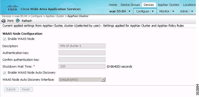
Step 3![]() (Optional) To enable this WAAS node to handle traffic distributed by the ANC, check the Enable WAAS Node check box.
(Optional) To enable this WAAS node to handle traffic distributed by the ANC, check the Enable WAAS Node check box.
Step 4![]() (Optional) In the Description field, enter the WAAS node description. Use only letters and numbers, up to a maximum of 200 characters are allowed.
(Optional) In the Description field, enter the WAAS node description. Use only letters and numbers, up to a maximum of 200 characters are allowed.
Step 5![]() (Optional) In the Authentication Key and Confirm Authentication Key fields, enter an authentication key that is used to authenticate communications between the WAAS node and the ANC. Use only letters and numbers, up to a maximum of 64 characters.
(Optional) In the Authentication Key and Confirm Authentication Key fields, enter an authentication key that is used to authenticate communications between the WAAS node and the ANC. Use only letters and numbers, up to a maximum of 64 characters.
Step 6![]() (Optional) In the Shutdown Wait Time field, enter the number of seconds that the WAAS node should wait for all the connections to be terminated before shutting down. The default is 120 seconds.
(Optional) In the Shutdown Wait Time field, enter the number of seconds that the WAAS node should wait for all the connections to be terminated before shutting down. The default is 120 seconds.
Step 7![]() (Optional) To enable automatic discovery of this WAAS node by the ANC, check the Enable WAAS Node Auto Discovery check box. (This feature is not used on WAAS nodes with Cisco WAAS Version 5.1 and earlier.)
(Optional) To enable automatic discovery of this WAAS node by the ANC, check the Enable WAAS Node Auto Discovery check box. (This feature is not used on WAAS nodes with Cisco WAAS Version 5.1 and earlier.)
This setting is intended to allow an AppNav-XE ANC to discover WAAS nodes that are to participate in a cluster that is created by the Cisco WAAS CLI and not configured by the Cisco WAAS Central Manager.
Step 8![]() From the WAAS Node Auto Discovery Interface drop-down list, choose the WN interface that is to be used for auto discovery. (This feature is not used on WAAS nodes with Cisco WAAS version 5.1 and earlier.)
From the WAAS Node Auto Discovery Interface drop-down list, choose the WN interface that is to be used for auto discovery. (This feature is not used on WAAS nodes with Cisco WAAS version 5.1 and earlier.)
To configure AppNav Cluster settings at the cluster level, see Configuring AppNav Cluster Settings. If you are using an authentication key to authenticate communications, you must configure the cluster and each WAAS node with the same key.
Note![]() Do not use both automatic node discovery and the Cisco WAAS Central Manager to add a WAAS node to an AppNav-XE cluster. We recommend that you disable automatic node discovery in AppNav-XE and then register the device and add it to the cluster with the Cisco WAAS Central Manager.
Do not use both automatic node discovery and the Cisco WAAS Central Manager to add a WAAS node to an AppNav-XE cluster. We recommend that you disable automatic node discovery in AppNav-XE and then register the device and add it to the cluster with the Cisco WAAS Central Manager.
Adding and Removing Devices from the AppNav Cluster
Adding an ANC to a Cluster
To add a new ANC to an AppNav Cluster, follow these steps:
Step 1![]() Configure the basic device and network settings on each new ANC, and ensure that the device mode is set to appnav-controller on a Cisco WAAS appliance.
Configure the basic device and network settings on each new ANC, and ensure that the device mode is set to appnav-controller on a Cisco WAAS appliance.
Step 2![]() From the Cisco WAAS Central Manager menu, choose AppNav Clusters > cluster-name.
From the Cisco WAAS Central Manager menu, choose AppNav Clusters > cluster-name.
Step 3![]() Click the AppNav Controllers tab below the topology diagram.
Click the AppNav Controllers tab below the topology diagram.
Step 4![]() Click the Add AppNav Controller taskbar icon.
Click the Add AppNav Controller taskbar icon.
The Add AppNav Controllers pane appears.
Step 5![]() Select the ANC devices to add:
Select the ANC devices to add:
a.![]() Select one or more ANCs in the AppNav Controller device list by checking the check boxes next to the device names. You can use the filter settings in the taskbar to filter the device list.
Select one or more ANCs in the AppNav Controller device list by checking the check boxes next to the device names. You can use the filter settings in the taskbar to filter the device list.
If there are devices that are ineligible to join the cluster, click Show Ineligible Devices to see them and the reasons why they are ineligible. You can use the filter settings to filter the list.
Step 6![]() Configure the interception method, policy, WCCP settings (if using WCCP interception), VRFs, and interfaces for each ANC device you are adding (different screens and options appear for Cisco WAAS appliance and AppNav-XE clusters):
Configure the interception method, policy, WCCP settings (if using WCCP interception), VRFs, and interfaces for each ANC device you are adding (different screens and options appear for Cisco WAAS appliance and AppNav-XE clusters):
a.![]() From the Interception Method drop-down list, choose WCCP or Inline. (This feature is not used on AppNav-XE clusters.)
From the Interception Method drop-down list, choose WCCP or Inline. (This feature is not used on AppNav-XE clusters.)
b.![]() From the AppNav Policy-Map drop-down list, choose the AppNav policy to apply to the ANC. (Not used on AppNav-XE clusters.)
From the AppNav Policy-Map drop-down list, choose the AppNav policy to apply to the ANC. (Not used on AppNav-XE clusters.)
c.![]() (Optional) To enable optimization on the ANC devices, check the Enable WAN optimization (Internal WAAS Node) check box. (This feature is not used on AppNav-XE clusters.)
(Optional) To enable optimization on the ANC devices, check the Enable WAN optimization (Internal WAAS Node) check box. (This feature is not used on AppNav-XE clusters.)
d.![]() (Optional) If you enabled WAN optimization, from the WAAS Node Group drop-down list, choose the WNG to which the internal WAAS node should belong. (This feature is not used on AppNav-XE clusters.)
(Optional) If you enabled WAN optimization, from the WAAS Node Group drop-down list, choose the WNG to which the internal WAAS node should belong. (This feature is not used on AppNav-XE clusters.)
f.![]() (Optional) If you chose WCCP interception, configure the WCCP settings on the WCCP settings pane that appears. For details on WCCP settings, see Configuring or Viewing the WCCP Settings on ANCs in the chapter “Configuring Traffic Interception” .
(Optional) If you chose WCCP interception, configure the WCCP settings on the WCCP settings pane that appears. For details on WCCP settings, see Configuring or Viewing the WCCP Settings on ANCs in the chapter “Configuring Traffic Interception” .
Note![]() Remember to check the Enable WCCP Service check box to enable WCCP.
Remember to check the Enable WCCP Service check box to enable WCCP.
g.![]() If you configured WCCP settings, click Next.
If you configured WCCP settings, click Next.
h.![]() On an AppNav-XE cluster, choose the VRF instances to associate with the service context by checking the check box next to each VRF instance that you want to use. If you choose the VRF default, you cannot choose other VRFs. If you choose multiple VRFs, they must not have overlapping source IP addresses. Only VRFs that are available on all the ANCs are listed.
On an AppNav-XE cluster, choose the VRF instances to associate with the service context by checking the check box next to each VRF instance that you want to use. If you choose the VRF default, you cannot choose other VRFs. If you choose multiple VRFs, they must not have overlapping source IP addresses. Only VRFs that are available on all the ANCs are listed.
j.![]() Configure the ANC interception interfaces. On a Cisco WAAS appliance cluster, you use the Cluster Interface Wizard graphical interface and on an AppNav-XE cluster, choose from a list of router interfaces.
Configure the ANC interception interfaces. On a Cisco WAAS appliance cluster, you use the Cluster Interface Wizard graphical interface and on an AppNav-XE cluster, choose from a list of router interfaces.
If you chose inline interception on a Cisco WAAS appliance, you must configure a bridge group interface. For details on using the wizard, see the Configuring Interfaces with the Graphical Interface Wizard.
k.![]() From the Cluster Interface drop-down list, choose the interface to be used for intracluster traffic.
From the Cluster Interface drop-down list, choose the interface to be used for intracluster traffic.
l.![]() (Optional) To enable swapping of client and WAAS device source IP address fields in intracluster traffic, check the Enable swapping of source IP address in intra-cluster traffic check box. (Not available on AppNav-XE clusters.)
(Optional) To enable swapping of client and WAAS device source IP address fields in intracluster traffic, check the Enable swapping of source IP address in intra-cluster traffic check box. (Not available on AppNav-XE clusters.)
Enable this option if you are using a port channel for the cluster interface or there is a load-balancing device between the ANC and WAAS node. This option can improve load balancing of the traffic that the ANC distributes to WAAS nodes for optimization because it load balances based on the client IP address rather than the ANC IP address. (For traffic from the server to the client, it swaps the server IP address with the ANC IP address.)
Note![]() The Cisco WAAS Central Manager enables this feature automatically if any existing ANCs have port channel cluster interfaces.
The Cisco WAAS Central Manager enables this feature automatically if any existing ANCs have port channel cluster interfaces.
m.![]() Click Next to save the settings and continue with the next ANC you are adding. If this is the last ANC being added, click Finish.
Click Next to save the settings and continue with the next ANC you are adding. If this is the last ANC being added, click Finish.
After a convergence waiting period of up to two minutes, the new ANCs are available in the cluster for traffic interception and distribution. Traffic interception on the new ANCs is prevented until the devices have fully joined the cluster. You can monitor the ANC status as described in Monitoring an AppNav Cluster.
Removing or Disabling an ANC from a Cluster
To gracefully remove an ANC from an AppNav Cluster, follow these steps:
Step 1![]() Disable the traffic interception path on the ANC. For an inline ANC, shut down the in-path interfaces, and for an ANC using WCCP, disable WCCP.
Disable the traffic interception path on the ANC. For an inline ANC, shut down the in-path interfaces, and for an ANC using WCCP, disable WCCP.
Traffic that was previously routed to this ANC is rerouted to other ANCs in the cluster.
Step 2![]() Disable the ANC (not necessary on an AppNav-XE cluster):
Disable the ANC (not necessary on an AppNav-XE cluster):
a.![]() From the Cisco WAAS Central Manager menu, choose AppNav Clusters > cluster-name.
From the Cisco WAAS Central Manager menu, choose AppNav Clusters > cluster-name.
b.![]() Click the AppNav Controllers tab below the topology diagram.
Click the AppNav Controllers tab below the topology diagram.
c.![]() Click the radio button next to the ANC that you want to disable and then click the Disable taskbar icon.
Click the radio button next to the ANC that you want to disable and then click the Disable taskbar icon.
The ANC is disabled and the service unreachable alarm is raised on the other ANCs in the cluster.
–![]() Click the radio button next to the ANC that you want to remove.
Click the radio button next to the ANC that you want to remove.
–![]() Click the Delete taskbar icon.
Click the Delete taskbar icon.
The ANC is removed from the ANCG on all the other ANCs and clears the service unreachable alarm on the other ANCs.
If the ANC is configured for WCCP interception, all the WCCP settings on the device are removed. If the ANC is also configured as a WN, the WN is removed from the cluster.
Step 3![]() (Optional) Power down the ANC.
(Optional) Power down the ANC.
Adding a New WAAS Node to the Cluster
To add a new WAAS node to a cluster, follow these steps:
Step 1![]() From the Cisco WAAS Central Manager menu, choose AppNav Clusters > cluster-name.
From the Cisco WAAS Central Manager menu, choose AppNav Clusters > cluster-name.
Step 2![]() Click the WAAS Nodes tab below the topology diagram.
Click the WAAS Nodes tab below the topology diagram.
Step 3![]() Click the Add WAAS Node taskbar icon.
Click the Add WAAS Node taskbar icon.
The Add WAAS Nodes pane appears.
Step 4![]() Select one or more WAAS nodes in the WAAS Nodes device list by checking the check boxes next to the device names. You can use the filter settings in the taskbar to filter the device list.
Select one or more WAAS nodes in the WAAS Nodes device list by checking the check boxes next to the device names. You can use the filter settings in the taskbar to filter the device list.
If there are devices that are ineligible to join the cluster, click Show Ineligible Devices to see them and the reasons why they are ineligible. You can use the filter settings to filter the list.
Step 6![]() Configure the WNG and interfaces for each WN device you are adding:
Configure the WNG and interfaces for each WN device you are adding:
a.![]() From the WAAS Node Group drop-down list, choose the WNG to which you want to add the new WAAS nodes. The list shows only the defined WNGs.
From the WAAS Node Group drop-down list, choose the WNG to which you want to add the new WAAS nodes. The list shows only the defined WNGs.
c.![]() Use the Cluster Interface Wizard graphical interface to configure the WAAS node interfaces. For details on using this wizard, see Configuring Interfaces with the Graphical Interface Wizard.
Use the Cluster Interface Wizard graphical interface to configure the WAAS node interfaces. For details on using this wizard, see Configuring Interfaces with the Graphical Interface Wizard.
d.![]() From the Cluster Interface drop-down list, choose the interface to be used for intra-cluster traffic.
From the Cluster Interface drop-down list, choose the interface to be used for intra-cluster traffic.
e.![]() (Optional) To enable swapping of client and Cisco WAAS device source IP address fields in intra-cluster traffic, check the Enable swapping of source IP address in intra-cluster traffic check box. (Not available for AppNav-XE clusters.)
(Optional) To enable swapping of client and Cisco WAAS device source IP address fields in intra-cluster traffic, check the Enable swapping of source IP address in intra-cluster traffic check box. (Not available for AppNav-XE clusters.)
Enable this option if you are using a port channel for the cluster interface, or there is a load-balancing device between the ANC and WAAS node. This option can improve load balancing of the traffic that the ANC distributes to WNs for optimization because it load balances based on the client IP address rather than the ANC IP address. (For traffic from the server to the client, it swaps the server IP address with the ANC IP address.)
Note![]() The Cisco WAAS Central Manager enables this feature automatically if any existing ANCs have port channel cluster interfaces.
The Cisco WAAS Central Manager enables this feature automatically if any existing ANCs have port channel cluster interfaces.
f.![]() Click Next to save the settings and continue with the next WN you are adding.
Click Next to save the settings and continue with the next WN you are adding.
If this is the last WN being added, click Finish.
Step 7![]() Configure and enable optimization on the WNs. For details on configuring optimization, see Chapter12, “Configuring Application Acceleration”
Configure and enable optimization on the WNs. For details on configuring optimization, see Chapter12, “Configuring Application Acceleration”
After a convergence waiting period of up to two minutes, the new WNs are available on all the ANCs for optimization.
Removing a WAAS Node from a Cluster
To remove a WAAS node from a cluster, follow these steps:
Step 1![]() From the WAAS Central Manager menu, choose AppNav Clusters > cluster-name.
From the WAAS Central Manager menu, choose AppNav Clusters > cluster-name.
Step 2![]() Click the WAAS Nodes tab below the topology diagram.
Click the WAAS Nodes tab below the topology diagram.
Step 3![]() Choose the node and click the Disable taskbar icon.
Choose the node and click the Disable taskbar icon.
This causes a graceful exit of the WAAS node from the cluster. The ANCs stop sending new flows to the WAAS node but continue to distribute existing flows to it until the connection count reaches zero, or the maximum shutdown wait time expires.
Note![]() The default shutdown wait time is 120 seconds. You can configure it from the Shutdown Wait Time field in the AppNav Cluster tab.
The default shutdown wait time is 120 seconds. You can configure it from the Shutdown Wait Time field in the AppNav Cluster tab.
Step 4![]() (Optional) When the graceful exit process on the WAAS node is complete (all existing connections have terminated), remove the WAAS node from the WNG on the ANCs by choosing the node and clicking the Delete taskbar icon.
(Optional) When the graceful exit process on the WAAS node is complete (all existing connections have terminated), remove the WAAS node from the WNG on the ANCs by choosing the node and clicking the Delete taskbar icon.
You can monitor the node status in the topology diagram in the upper part of the window. The colored status light indicator on the device turns gray when the node is no longer processing connections.
Step 5![]() (Optional) Power down the WAAS node.
(Optional) Power down the WAAS node.
Adding a New WAAS Node Group to the Cluster
To add a new WNG to a cluster, follow these steps:
Step 1![]() From the Cisco WAAS Central Manager menu, choose AppNav Clusters > cluster-name.
From the Cisco WAAS Central Manager menu, choose AppNav Clusters > cluster-name.
Step 2![]() Click the WAAS Node Groups tab below the topology diagram.
Click the WAAS Node Groups tab below the topology diagram.
Step 3![]() Click the Add WAAS Node Group taskbar icon.
Click the Add WAAS Node Group taskbar icon.
The Add WAAS Node Group pane appears.
Step 4![]() In the Name field, enter the name of the WNG. On a WAAS appliance cluster, you can enter up to 32 alphanumeric characters, and on an AppNav-XE cluster, you can enter up to 64 characters, excluding a space.
In the Name field, enter the name of the WNG. On a WAAS appliance cluster, you can enter up to 32 alphanumeric characters, and on an AppNav-XE cluster, you can enter up to 64 characters, excluding a space.
Step 5![]() (Optional) In the Description field, enter a description of the WNG. You can enter up to 200 alphanumeric characters, including ' | \ ; ` on a WAAS appliance cluster. In an AppNav-XE cluster, you can enter up to 241 characters, excluding a space.
(Optional) In the Description field, enter a description of the WNG. You can enter up to 200 alphanumeric characters, including ' | \ ; ` on a WAAS appliance cluster. In an AppNav-XE cluster, you can enter up to 241 characters, excluding a space.
Step 6![]() Click OK to save the settings.
Click OK to save the settings.
Step 7![]() Add one or more WAAS nodes to the new WNG. To add a new WAAS node, see Adding a New WAAS Node to the Cluster, or to reassign an existing WAAS node to the new WNG, see Configuring WAAS Node Settings.
Add one or more WAAS nodes to the new WNG. To add a new WAAS node, see Adding a New WAAS Node to the Cluster, or to reassign an existing WAAS node to the new WNG, see Configuring WAAS Node Settings.
After a convergence waiting period of up to two minutes, the new WNG is available on all the ANCs for optimization.
Removing a WAAS Node Group from a Cluster
To remove a WAAS node group (WNG) from a cluster, follow these steps:
Step 1![]() From the Cisco WAAS Central Manager menu, choose AppNav Clusters > cluster-name.
From the Cisco WAAS Central Manager menu, choose AppNav Clusters > cluster-name.
Step 2![]() Click the WAAS Nodes tab below the topology diagram.
Click the WAAS Nodes tab below the topology diagram.
Step 3![]() Click the radio button next to the node name you want to disable and click the Disable taskbar icon. This causes a graceful exit of each WAAS node from the cluster.
Click the radio button next to the node name you want to disable and click the Disable taskbar icon. This causes a graceful exit of each WAAS node from the cluster.
Step 4![]() After all WAAS nodes have completed a graceful exit from the cluster, click the WAAS Node Groups tab.
After all WAAS nodes have completed a graceful exit from the cluster, click the WAAS Node Groups tab.
You can monitor the node status in the topology diagram in the upper part of the window. The colored status light indicator on the device turns gray when the node is no longer processing connections.
Step 5![]() (Optional) Choose the WNG you want to remove, and click the Delete taskbar icon.
(Optional) Choose the WNG you want to remove, and click the Delete taskbar icon.
Monitoring an AppNav Cluster
To monitor an AppNav Cluster, follow these steps:
Step 1![]() From the Cisco WAAS Central Manager menu, choose AppNav Clusters > cluster-name.
From the Cisco WAAS Central Manager menu, choose AppNav Clusters > cluster-name.
The Cluster home window displays the cluster topology and device status (see Figure 4-20).
Figure 4-20 AppNav Cluster Topology and Status
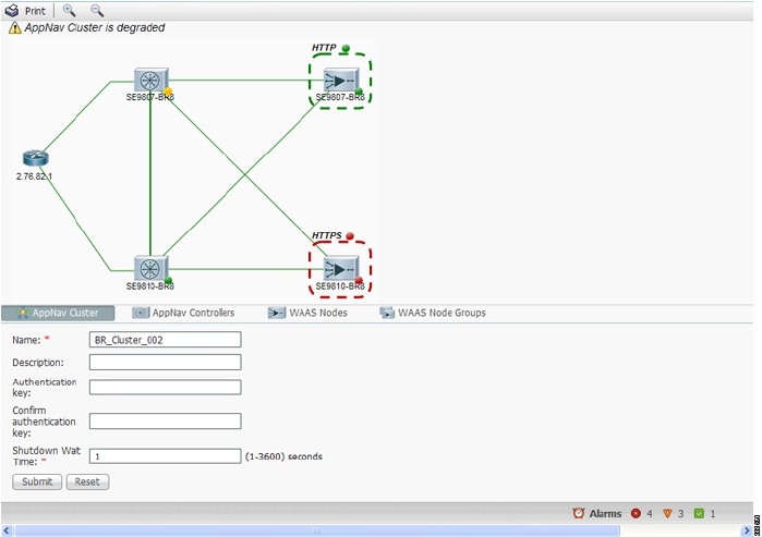
To zoom in or out on the topology diagram, click the + or – magnifying glass icons in the taskbar. You can also click on the diagram and drag it within the window to reposition it.
To change the cluster settings, edit any of the fields in the Cluster Settings tab below the topology diagram and click Submit.
Note![]() On AppNav-XE clusters, the Name and Description fields are not shown.
On AppNav-XE clusters, the Name and Description fields are not shown.
To see all the AppNav contexts, click the AppNav Contexts tab below the diagram. From this tab, you can edit, delete, add, enable, or disable an AppNav context. This tab is not shown on WAAS appliance clusters.
To see all the ANCs, click the AppNav Controllers tab below the diagram. From this tab, you can edit, delete, add, enable, or disable an ANC in the cluster.
To see all the WAAS nodes, click the WAAS Nodes tab below the diagram. From this tab, you can edit, delete, add, enable, or disable a WAAS node in the cluster.
To see all the WNGs, click the WAAS Node Groups tab below the diagram. From this tab, you can edit, delete, or add a WNG in the cluster.
The overall cluster status is shown in the top left corner of the diagram, as follows:
- Green: All the ANCs are operational with no error conditions.
- Yellow: Degraded because one or more ANCs have operational issues. This is also the initial state before all the nodes have sent status updates.
- Red: Cluster is down because all the ANCs are down, or indicates a split cluster where there is no connectivity between one or more ANCs.
The overall cluster status does not include administratively disabled ANCs.
The colored status light indicators on each device and dotted lines around each WNG show the status of the device or group:
- Green: Operational with no error conditions
- Yellow: Degraded (overloaded, joining cluster, or has other noncritical operational issues)
- Red: Critical (one or more processes is in a critical state)
- Gray: Disabled
- Black: Unknown status
The colored lines between each device show the status of the link between devices:
A red plus symbol (+) is shown on the upper right corner of any device that is added to an AppNav-XE cluster by automatic node discovery. The cluster configuration of such a device is not being managed by the Cisco WAAS Central Manager and you should verify that its configuration is correct. Additionally, statistics from the device are not aggregated in any Cisco WAAS Central Manager reports if the device is not registered to the Cisco WAAS Central Manager; if the device is registered to the Central Manager, its optimization (but not AppNav) statistics are included in Cisco WAAS Central Manager reports.
Note![]() Do not use both automatic node discovery and the Cisco WAAS Central Manager to add a WAAS node to an AppNav-XE cluster. We recommend that you disable automatic node discovery in AppNav-XE and then register the device and add it to the cluster with the Cisco WAAS Central Manager. For details on configuring auto discovery, see ConfiguringCisco AppNav Cluster Settings for a Cisco WAAS Node.
Do not use both automatic node discovery and the Cisco WAAS Central Manager to add a WAAS node to an AppNav-XE cluster. We recommend that you disable automatic node discovery in AppNav-XE and then register the device and add it to the cluster with the Cisco WAAS Central Manager. For details on configuring auto discovery, see ConfiguringCisco AppNav Cluster Settings for a Cisco WAAS Node.
An orange triangle  warning indicator is shown on any device for which the Cisco WAAS Central Manager may not have current information because the device has not responded within the last 60 seconds (the device could be offline or unreachable).
Note![]() A recently removed device still appears in the topology diagram for a few minutes until all the devices agree on the new cluster topology.
A recently removed device still appears in the topology diagram for a few minutes until all the devices agree on the new cluster topology.
To view a more comprehensive device status display, hover your cursor over a device icon to see the 360-degree Network Device View dialog box (Figure 4-21). (The dialog box for a WAAS node device is similar.)
Figure 4-21 ANC 360-Degree Network Device View
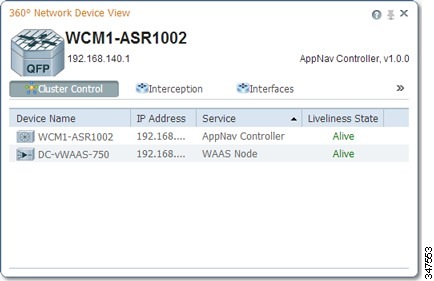
The 360-degree Network Device View dialog box shows the following status information:
- Device name and IP address.
- Device type and software version.
- (ANC only) Interception tab that displays the interception method for a WAAS appliance (Inline or WCCP). For inline, this tab shows the bridge groups defined for interception, their member interfaces, and their status. For WCCP, this tab lists the defined WCCP service IDs, their associated client IP addresses, router IP address, and notes about problems. For an AppNav-XE device, this tab shows the router interfaces on which interception is enabled and their status.
- (ANC only) Overloaded Policies tab that lists monitored AppNav policies that are overloaded. (Not shown on AppNav-XE devices.)
- (ANC only) Cluster Control tab that lists all the devices in the cluster, along with device name, IP address, service type, liveliness state, and reason for any error condition.
- (WN only) Optimization tab that lists the application accelerators and their status.
- Alarms tab that lists pending alarms on the device. (Not shown on AppNav-XE devices.)
- Interfaces tab that lists the device interfaces and status. You can filter the list by choosing a filter type from the drop-down list above the interface list, entering filter criteria, and clicking the filter icon.
You can pin the status dialog box so it stays open by clicking the pin icon in the upper right corner. You can also drag the dialog box to any location within your browser window.
For additional cluster status, you can view the Monitor > AppNav > AppNav Report, as described in the AppNav Report in the chapter “Monitoring Your Cisco WAAS Network” .
If you have multiple AppNav Clusters, you can see the brief status for all of them at once by choosing AppNav Clusters > All AppNav Clusters from the menu.
To trace connections in a WAAS appliance cluster, see AppNav Connection Tracing.
To view connection statistics in an AppNav-XE cluster, see AppNav Connection Statistics.
Note![]() You may see a taskbar icon named Force Settings on all the devices in a group if the configuration across all the ANCs in the cluster becomes unsynchronized. If you see the icon, it means that the cluster settings, ANC configuration, WAAS node configuration, and WNG configuration do not match on all the ANCs in the cluster. This scenario may occur if you configure a device outside the Cisco WAAS Central Manager by using the Cisco WAAS CLI. Click the Force Settings taskbar icon to update all the devices with the configuration that is currently shown in the Cisco WAAS Central Manager for the cluster.
You may see a taskbar icon named Force Settings on all the devices in a group if the configuration across all the ANCs in the cluster becomes unsynchronized. If you see the icon, it means that the cluster settings, ANC configuration, WAAS node configuration, and WNG configuration do not match on all the ANCs in the cluster. This scenario may occur if you configure a device outside the Cisco WAAS Central Manager by using the Cisco WAAS CLI. Click the Force Settings taskbar icon to update all the devices with the configuration that is currently shown in the Cisco WAAS Central Manager for the cluster.
Note![]() The Force Device Group icon appears in the AppNav XE Cluster page when you downgrade the router from a PassThrough FlowSync supported software version, such as Cisco IOS XE 17.2 to a non-supported software version, Cisco IOS XE 16.9.3. To prevent this from happening, de-select the Disable PassThrough FlowSync check box before performing the downgrade.
The Force Device Group icon appears in the AppNav XE Cluster page when you downgrade the router from a PassThrough FlowSync supported software version, such as Cisco IOS XE 17.2 to a non-supported software version, Cisco IOS XE 16.9.3. To prevent this from happening, de-select the Disable PassThrough FlowSync check box before performing the downgrade.
AppNav Connection Tracing
To assist in troubleshooting AppNav flows in a WAAS appliance cluster, use the Connection Trace tool in the Cisco WAAS Central Manager. This tool shows the following information for a particular connection:
- Whether the connection was passed through or distributed to a WNG
- Pass-through reason, if applicable
- The WNG and WAAS node to which the connection was distributed
- Accelerator monitored for the connection
- Class-map applied
To use the Connection Trace tool, follow these steps:
Step 1![]() From the Cisco WAAS Central Manager menu, choose AppNav Clusters > cluster-name.
From the Cisco WAAS Central Manager menu, choose AppNav Clusters > cluster-name.
Step 2![]() Choose Monitor > Tools > Connection Trace.
Choose Monitor > Tools > Connection Trace.
Step 3![]() From the AppNav Controller drop-down list, choose the ANC that has the connection that you want to trace.
From the AppNav Controller drop-down list, choose the ANC that has the connection that you want to trace.
Step 4![]() From the Site (Remote Device) drop-down list, choose the peer WAAS device at the remote site.
From the Site (Remote Device) drop-down list, choose the peer WAAS device at the remote site.
Step 5![]() In one or more of the Source IP, Source Port, Destination IP, and Destination Port fields, enter matching criteria for one or more connections.
In one or more of the Source IP, Source Port, Destination IP, and Destination Port fields, enter matching criteria for one or more connections.
Step 6![]() Click Trace to display the connections that match the IP address and port criteria.
Click Trace to display the connections that match the IP address and port criteria.
Connections are displayed in the Connection Tracing Results table below the fields. Use the filter settings in the Show drop-down list to filter the connections, as required. You can use Quick Filter to filter on any value or Show All Connections.
You can display flow distribution information from the Cisco WAAS CLI by using the show appnav-controller flow-distribution EXEC command.
Another troubleshooting tool that you can use to trace connections on a WAAS appliance AppNav cluster is the WAAS TCP Traceroute tool. For details, see Using WAASTCP Traceroute in the chapter “Troubleshooting Your Cisco WAAS Network” .
AppNav Connection Statistics
To view AppNav connection statistics in an AppNav-XE cluster, follow these steps:
Step 1![]() From the Cisco WAAS Central Manager menu, choose AppNav Clusters > cluster-name.
From the Cisco WAAS Central Manager menu, choose AppNav Clusters > cluster-name.
Step 2![]() Choose Monitor > Tools > Connection Statistics.
Choose Monitor > Tools > Connection Statistics.
Step 3![]() From the AppNav Controller drop-down list, choose the ANC from which you want to view statistics.
From the AppNav Controller drop-down list, choose the ANC from which you want to view statistics.
Step 4![]() In the Source IP Address, Source Port, Destination IP Address, Destination Port, and Vrf Name fields, enter matching criteria for one or more connections.
In the Source IP Address, Source Port, Destination IP Address, Destination Port, and Vrf Name fields, enter matching criteria for one or more connections.
Step 5![]() Click Submit to display the connection statistics that match the IP address and port criteria.
Click Submit to display the connection statistics that match the IP address and port criteria.
Connections are displayed in the Connection Statistics table below the fields. Use the filter settings in the Show drop-down list to filter the connections, as required. You can use Quick Filter to filter on any value or Show All Connections.
You can display connection statistics from the Cisco WAAS CLI by using the show service-insertion statistics connection EXEC command.
 Feedback