Introduction
This document describes new memory features introduced in UCS M7 and M8 Generation Servers and steps to Understand & Troubleshoot memory errors
Prerequisites
Requirements
Cisco recommends that you have knowledge of these topics.
- Basic understanding of UCS.
- Basic understanding of Memory Architecture.
Components Used
The information in this document is based on these software and hardware versions:
- UCS Family Servers M7 and M8
- UCS Manager
- Cisco Integrated Management Controller (CIMC)
- Cisco Intersight Managed Mode (IMM)
The information in this document was created from the devices in a specific lab environment. All of the devices used in this document started with a cleared (default) configuration. If your network is live, ensure that you understand the potential impact of any command.
Background Information
Overview of memory errors
Memory errors are among the most common types of errors on modern servers. Errors are often discovered when an attempt is made to read a memory location and the value read does not match the value last written.
Memory errors can be soft or hard. Some errors are correctable, but multiple simultaneous soft or hard errors on a single memory access can be uncorrectable.
Cisco UCS M7/M8 Memory RAS features
Cisco UCS M7 & M8 servers have a robust set of RAS features, as detailed here. These minimize the impact of memory errors on performance and system uptime.
System-level ECC
All Cisco UCS M7 servers use memory modules with ECC codes that can correct any error confined to a single x4 DRAM chip and detect any double-bit error in up to two devices. This is now referred to as system-level ECC, as in older-generation servers
.
Virtual Lock-Step (VLS) / Adaptive Double Device Data Correction (ADDDC) Sparing
ADDDC Sparing can correct two successive DRAM failures if they reside in the same region. This feature tracks correctable errors and dynamically maps out failing bits by spare-copying (“sparing”) contents into a “buddy” cache line. This mechanism can mitigate correctable errors that, if left untreated, could become uncorrectable. This feature uses virtual lockstep (VLS) to assign cache-line buddy pairs within the same memory channel at either the DRAM bank-level using bank VLS or the DRAM device-level using rank VLS.
.
On-die ECC
On-die ECC is a new feature in DDR5. This feature is enabled by default. All single-bit errors (hard and soft) are corrected by DRAM before data is transmitted to the host. However, this corrected data is not written back to DRAM. Error Check and Scrub (ECS) is the feature used to scrub and correct single-bit errors in memory.
Error Check and Scrub (ECS)
ECS checks for errors in the background by scrubbing each DRAM die periodically (every 24 hours), correcting them by writing data back to the array and providing a count of the errors found during the scrub. This feature is enabled by default.
Post Package Repair (PPR)
Post package repair is a feature where spare rows are used to replace a bad cell or row in a DRAM device.
There are three types:Soft PPR(reconfigurable),Hard PPR(permanent), andRuntime PPR.
- Cisco UCS M7 servers with Intel CPUs support “hard” PPR. This is a permanent repair and is carried out during reboot based on the error data collected during the previous runtime or if any row errors are encountered during EMT.
- Repairs typically occur during warm/cold resets or AC cycles.
- On the UCS M8 support all three type of PPR ,Hard PPR is enabled by default, whileRuntime PPR is disabled.
- Runtime PPRallows repairs to happen during system operation without affecting uptime.
- If both Hard and Runtime PPR are enabled, all PPR features are utilized. If Hard PPR is disabled but Runtime PPR is enabled, the system defaults to Soft PPR.
- PPR is closely linked with correctable errors, and each correctable error generate a SEL record when PPR is enabled.
PMIC (Power Management Integrated Circuit)
The PMIC on a DIMM is a key feature of DDR5 memory modules. This integration moves the power management function from the motherboard onto the memory module itself, offering several significant advantages.
For DDR5 memory, PMIC error handling is enabled.
- PMIC failures generate CELL records during both runtime and post-boot.
- During memory training, if a PMIC failure is detected in a memory channel, the affected DIMM is mapped out, and the system continues to boot with reduced memory
Log Analysis
Files to Check in Tech Support
UCSM_X_TechSupport > sam_techsupportinfo provides information about DIMM and memory array.
Chassis/server tech support
CIMCX_TechSupport\tmp\CICMX_TechSupport.txt -> Generic tech support information about sever X.
CIMCX_TechSupport\obfl\obfl-log -> OBFL logs provide an ongoing logs about status and boot of server X.
CIMCX_TechSupport\var\log\sel -> SEL logs for server X.
Based on the platform/version, navigate to the files in tech support bundle.
RAS -For ECS (error Check and Scrub) CE error locationetc. collected during runtime on every scrub
/nv/etc/BIOS/bt/DDR5_CISCO_ECS
AMT Auto Executes in the next boot if hits CE & UCE Error on DIMMs
nv/etc/BIOS/bt/MrcOut.
AMT_TEST_PATTERN:
ADV_MT_SAMSUNG
AMT_RESULT: PASSED.
PMIC error: /nv/etc/DIMM-PMIC.txt
M8 server contains :-
nv/etc/BIOS/bt >MrcOut
These files provide information about memory as seen from BIOS level.
Information there can be cross-referenced again with DIMM states report tables.
Example from AMD server :-
nv/etc/BIOS/bt >MrcOut
It contains :
- BIOS version, build date and time
- PSP firmware versions
- DIMM Presence and status (indicates DIMM is present or not)
- DIMM configuration details.
2025/08/14 13:44:34

BIOS ID : C245M8.4.3.6b.0 Built 04/28/2025 14:15:22

=====================
PSP Firmware Versions
=====================
ABL Version: 100E8012
PSP: 0.29.0.9B
PFMW (SMU): 4.71.126.0
SEV: 1.1.37.28
PHY: 0.1.38.0
MPIO: 1.0.2D.C4
TF MPDMA: 0.47.3.0
PM MPDMA: 0.47.46.0
GMI: AB.1.27.0
RIB: 2.0.8.39
SEC: D.E.90.71
PMU: 0.0.90.4E
EMCR: 0.0.E0.4E
uCode B1: 0xA101154


DIMM Status:
|=======================|
| Memory | DIMM Status |
| Channel | |
|=======================|
| P1_A | 01 |
| P1_B | 01 |
| P1_C | 01 |
| P1_D | 01 |
| P1_E | 01 |
| P1_F | 00 |
| P1_G | 01 |
| P1_H | 01 |
| P1_I | 01 |
| P1_J | 01 |
| P1_K | 01 |
| P1_L | 00 |
| P2_A | 01 |
| P2_B | 01 |
| P2_C | 01 |
| P2_D | 01 |
| P2_E | 01 |
| P2_F | 00 |
| P2_G | 01 |
| P2_H | 01 |
| P2_I | 01 |
| P2_J | 01 |
| P2_K | 01 |
| P2_L | 00 |
|=======================|


DIMM Configuration:
=================================================
MbistTest = Disabled
MbistAggressor = Disabled
MbistPerBitSlaveDieReport = Enabled
DramTempControlledRefreshEn = Disabled
UserTimingMode = Disabled
UserTimingValue = Disabled
MemBusFreqLimit = Disabled
EnablePowerDown = Disabled
DramDoubleRefreshRate = Disabled
PmuTrainMode = 0x0000
EccSymbolSize = 0x0000
UEccRetry = Disabled
IgnoreSpdChecksum = Disabled
EnableBankGroupSwapAlt = Disabled
EnableBankGroupSwap = Disabled
DdrRouteBalancedTee = Disabled
OdtsCmdThrotEn = Disabled
OdtsCmdThrotCyc = Disabled
=================================================

Enhanced Memory Context Restore : APOB_SAVED

2025/08/14 13:44:34
MCA out file inventory :-
This file contains information about MCA registers of all banks .
(Whenever UCE Error has been detected)
--- START OF MCA FILE ---
Timestamp H:M:S 13:44:15 D:M:Y 14:8:2025

--- Note ---
The legacy MCA registers include:
MCA_CTL - Enables error reporting via machine check exception.
MCA_STATUS - Logs information associated with errors.
MCA_ADDR - Logs address information associated with errors. The use of AMD Secure Memory Encryption may change the information logged in the address register.
MCA_MISC0 - Logs miscellaneous information associated with errors.
The MCA Extension registers include:
MCA_CONFIG - Provide configuration capabilities for this MCA bank.
MCA_IPID - Provides information on the block associated with this MCA bank.
MCA_SYND - Logs physical location information associated with a logged error.
MCA_DESTATUS - Logs status information associated with a deferred error.
MCA_DEADDR - Logs address information associated with a deferred error.
MCA_MISC[1:4] - Provides additional threshold counters within an MCA bank.
MCA_TRANSSYND - Logs location information associated with a transparent error.
MCA_TRANSADDR - Logs address information associated with a transparent error.


LS - Load-Store Unit -> Bank 0
IF - Instruction Fetch Unit -> Bank 1
L2 - L2 Cache Unit -> Bank 2
DE - Decode Unit -> Bank 3
Empty/Unused bank -> Bank 4
EX - Execution Unit -> Bank 5
FP - Floating Point Unit -> Bank 6
L3 - L3 Cache Unit -> Bank 7 to 14
MP5 - Microprocessor5 Management Controller -> Bank 15
PB - Parameter Block -> Bank 16
PCS-GMI - GMI Controller -> Bank 17 to 18
KPX-GMI - High Speed Interface Unit(GMI) -> Bank 19 to 20
UMC - Unified Memory Controller -> Bank 21 to 22
CS - Coherent Station -> Bank 23 to 24
NBIO - NorthBridge IO Unit -> Bank 25
PCIE - PCIe Root port -> Bank 26 to 27
PIE - Power Management, Interrupts, Etc -> Bank 28
SMU - System Management Controller Unit -> Bank 29
PCS_XGMI - XGMI Controller -> Bank 30
KPX_SERDES - High Speed Interface Unit(XGMI)-> Bank 31
Empty/Unused bank -> Bank 32 to 63

Total BankNumber = 32
MC Global Capability Value = 120
MC Global Status Value = 0
MC Global Control Value = 0
Number of processor = 64
ProcNum BankNum Socket CCD CCX Core Thread MCA Bank Status MCA Bank Address MCA Configuration MCA IPID MSR VAL MCA SYND MSR VAL MC MISC0 MSR VAL MC MISC1 MSR VAL MC DESTAT MSR VAL MC DEADDR MSR VAL MC SYND1 MSR VAL MC SYND2 MSR VAL


Timestamp H:M:S 13:44:32 D:M:Y 14:8:2025
--- END OF MCA FILE ---
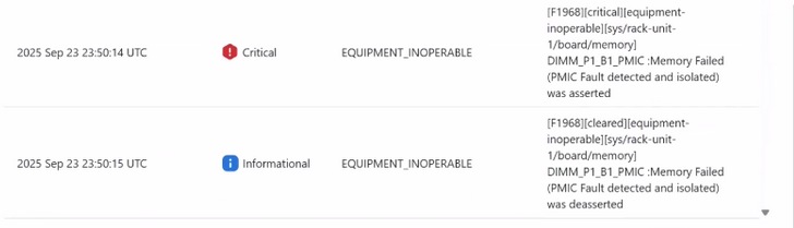
Example of PMIC failure in Sel logs :-
Whenever there is a runtime PMIC failure on the DIMM, SEL log will be generated as shown below, and the host is turned off.
- 2024-06-11 20:26:36 IST ◆Warning System Software event: Memory sensor, Memory Failed (PMIC Fault detected and isolated) was asserted, DIMM socket 1, Channel A, CPU 2. was asserted

The faulty DIMM is mapped out by the BIOS on next host power on . We see the below SEL

A fault is raised as shown below.

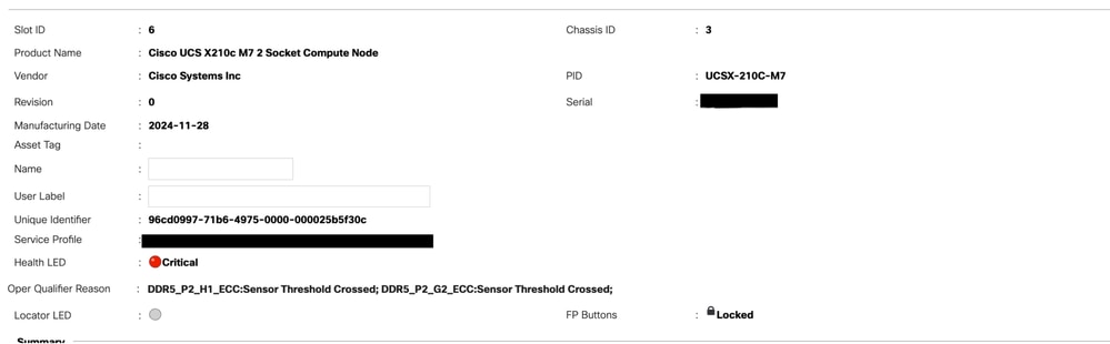
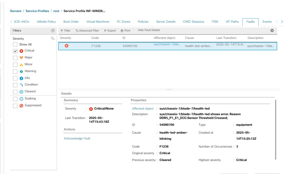
Troubleshooting RAS Faults
Generally, you see these faults in UCS Manager as an RAS event.
UCSM CLI commands to reset all memory error counters:
UCS-A# scope server x/y
UCS-A /chassis/server # reset-all-memory-errors
UCS-A /chassis/server* # commit
To clear the SPD data :
Power off the server
Then run the folloiwng commands from UCSM CLI :
UCS-A# connect cimc x/y
UCS-A /chassis/server # reset-all-memory-errors
UCS-A /chassis/server* # commit
Notable Bugs
1. Cisco bug ID CSCwo62396
2. Cisco bug ID CSCwq33148
3. Cisco bug ID CSCwh73760
 Feedback