Introduction
This document describes how to configure Secure Access with Catalyst SD-WAN Automated Tunnels for Secure Private Access.
Background Information
As organizations move beyond traditional perimeter based networks, securely accessing private resources becomes just as important as securing internet traffic. Applications are no longer confined to a single data center, they now live across on-premises environments, public clouds, and hybrid architectures. This shift requires a more flexible and modern approach to private access.
This is where a SASE based architecture and Cisco Secure Access come into play. Instead of relying on legacy VPN concentrators and flat network access, Cisco Secure Access provides private connectivity as a cloud delivered service, combining VPN-as-a-Service (VPNaaS) and Zero Trust Network Access (ZTNA).
For network-level private access, Cisco Secure Access integrates with SD-WAN using automated site-to-site IPsec tunnels. These tunnels allow private traffic to flow securely between Secure Access and on-premises or cloud networks, while keeping security inspection and policy enforcement centralized in the cloud. From an operational perspective, this removes the need to deploy and maintain traditional VPN headends and simplifies scaling as environments grow.
In a VPNaaS model, Secure Access acts as the VPN termination point in the cloud. SD-WAN handles intelligent routing and resiliency with Secure Access and ensures that traffic is protected and governed by consistent security policies before reaching private resources.
Cisco Secure Access also supports advanced site-to-site tunnel architectures, including multi-regional backhaul. This capability allows organizations to establish tunnels to multiple Secure Access regions simultaneously, providing geographic redundancy and higher availability. By connecting to different regions, traffic can fail over automatically in case of regional outages, latency degradation, or maintenance events.
For example, an organization can establish site-to-site tunnels from its SD-WAN environment to Secure Access regions in London and Germany. Both tunnels remain active, enabling resilient private access across regions and ensuring continuity even if one region becomes unavailable. This multi-regional design strengthens high availability, improves fault tolerance, and aligns with enterprise-grade resilience requirements.
For more granular access, Cisco Secure Access enforce Zero Trust Network Access (ZTNA) model. Instead of granting users broad network connectivity, ZTNA allows access only to specific applications, based on identity, device posture, and context. This approach significantly reduces the attack surface and aligns with Zero Trust principles.
ZTNA access is enabled through a combination of site-to-site tunnels and Resource Connectors. Resource Connectors are lightweight virtual appliances that establish outbound-only connections to Secure Access, meaning private resources never need to be exposed directly to the internet.
Network Diagram
Prerequisites
Requirements
- Secure Access Knowledge
- Cisco Catalyst SD-WAN Manager Release 20.18.2 and Cisco IOS XE Catalyst SD-WAN Release 17.18.2 or later
- Intermediate knowledge of routing and switching
- ECMP Knowledge
- VPN Knowledge
- Since this integration is on controlled availability, you need to submit a TAC case to ask to enable the feature in Cisco Secure Access
Components Used
- Secure Access Tenant
- Catalyst SD-WAN Manager Release 20.18.2 and Cisco IOS XE Catalyst SD-WAN Release 17.18.2
- Catalyst SD-WAN Manager
The information in this document was created from the devices in a specific lab environment. All of the devices used in this document started with a cleared (default) configuration. If your network is live, ensure that you understand the potential impact of any command.
Configure
Secure Access Configuration
API Creation
In order to create the automated tunnels with Secure Access check the next steps:
Navigate to Secure Access Dashboard.
- Click on
Admin > API Keys
- Click on
Add
- Choose the next options:
Deployments / Network Tunnel Group: Read/WritteDeployments / Tunnels: Read/WritteDeployments / Regions: Read-OnlyDeployments / Identities: Read-WritteExpiry Date: Never Expire
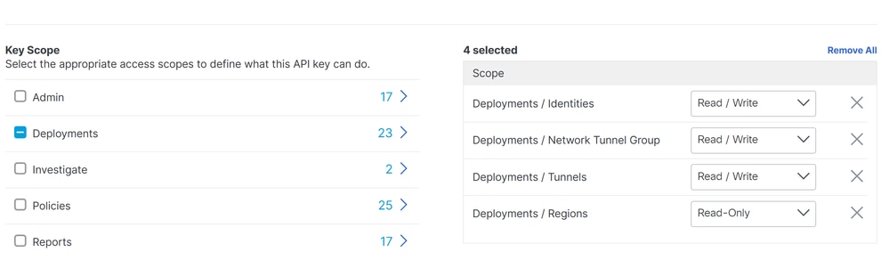
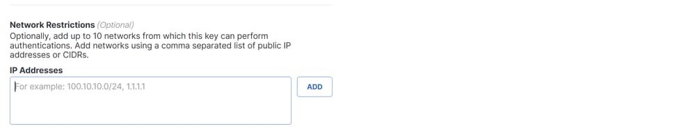


Note: Optionally, add up to 10 networks from which this key can perform authentications. Add networks using a comma separated list of public IP addresses or CIDRs.
- Click
CREATE KEY to finalize the creation of the API Key and Key Secret.


Caution: Copy them before you click ACCEPT AND CLOSE; otherwise, you need to create them again and delete the ones that were not copied.
Then to finalize click ACCEPT AND CLOSE.
SD-WAN Configuration
API Integration
Navigate to Catalyst SD-WAN Manager:
- Click on
Administration >Settings > Cloud Credentials
- Then click on
Cloud Provider Credentials and enable Cisco SSEand fill the API and Organtiazation Settings
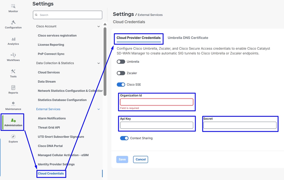
Then after that click on the Save button.
Note: Before you proceed with the next steps, you need to be sure that the SD-WAN Manager and the Catalyst SD-WAN Edges have DNS resolution and internet access.
To check if the DNS-Lookup is enabled please navigate to:
- Click on Configuration > Configuration Groups
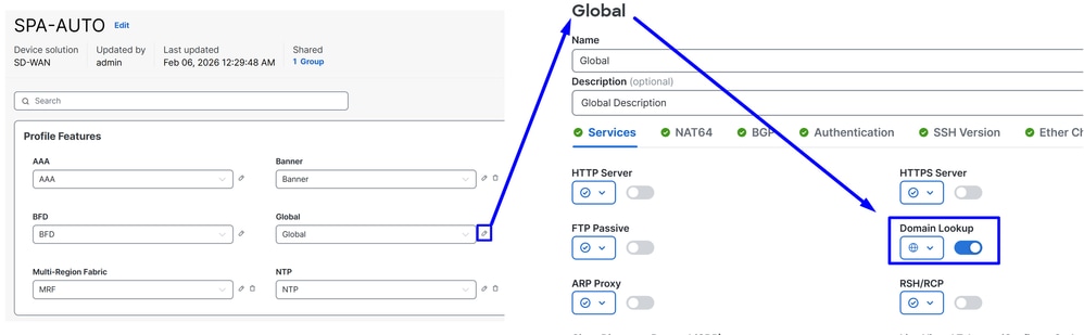
- Click on the profile of your Edge Devices and edit the System Profile
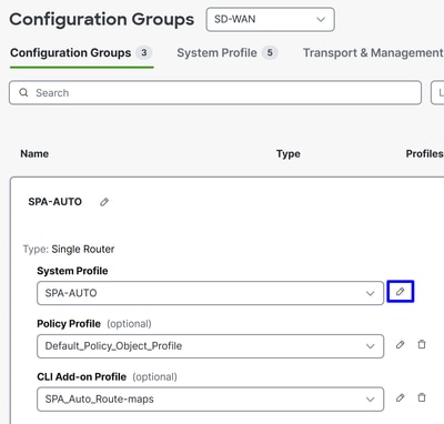
- Then Edit the Global option and be sure the option Domain Resolution is enabled
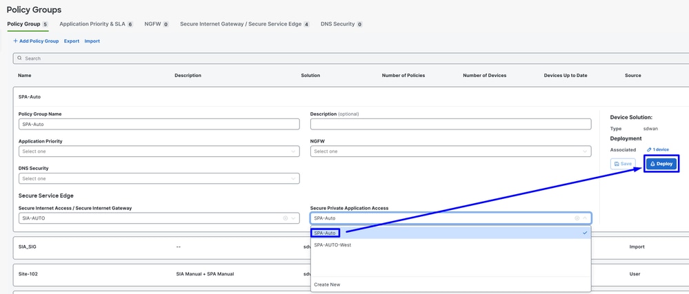
Configure Policy Group
Navigate toConfiguration > Policy Groups:
- Click on
Secure Internet Gateway / Secure Service Edge>Add Secure Private Access
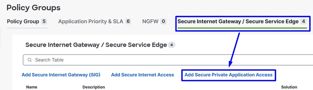
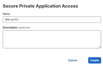
- Configure a name and click on
Create
The next configurations allows you to create the tunnels after you deploy the configuration in your Catalyst SD-WAN Edges:
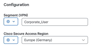
Configuration
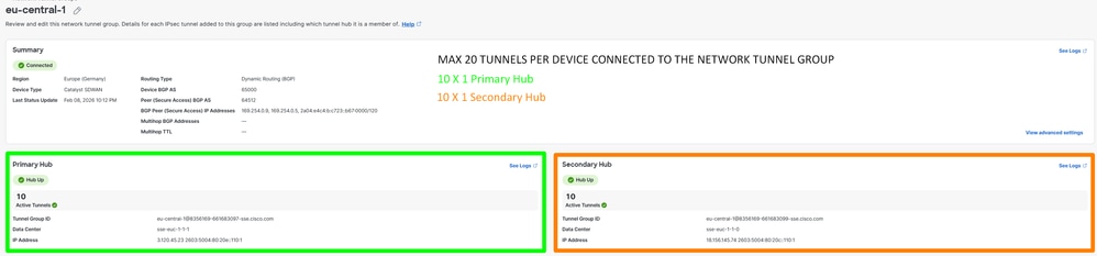
Segment (VPN): Choose the VRF that hosts the application(s) to be accessed through Secure AccessCisco Secure Access Region: Choose the region closest to the SD-WAN hub or branch where the applications are hosted
Next, define the tunnel configuration. Tunnels created to the Primary Secure Access Data Center are active, while tunnels created to the Secondary Secure Access Data Center operate as backup.
Under Tunnel Configuration click + Add Tunnel:

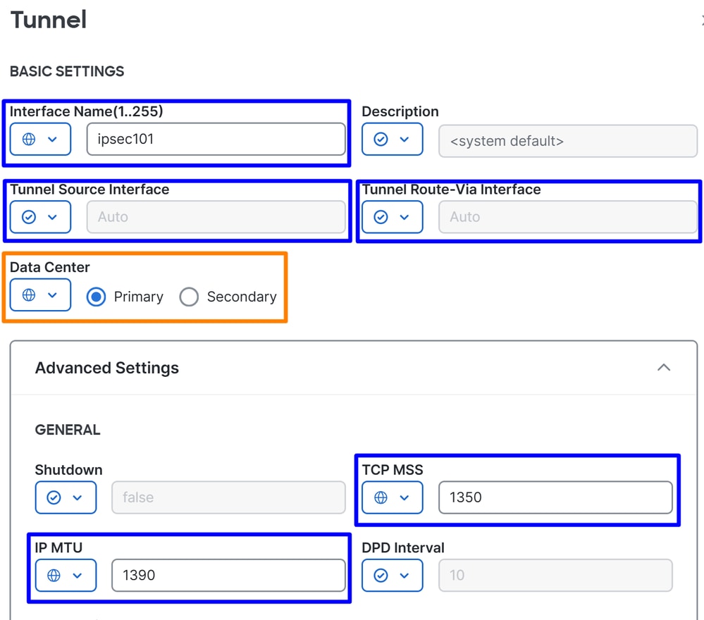
Tunnel
Interface Name: Specify tunnel name, it is automatically updated each time a new tunnel is addedTunnel Source Interface: You do not need to change this setting. When left as Auto, the system automatically creates a loopback interface with a /31 mask.Tunnel Route-Via Interface: You do not need to change this setting. By default, it uses the first NATed physical WAN interface on the edge router, but it can be changed if a specific WAN interface is requiredData Center: Select Primary or Secondary accordingly. If the primary tunnel is already configured, select Secondary. In normal scenarios, one tunnel can be configured as Primary and another as SecondaryAdvanced Settings
IP MTU: Use 1390TCP MSS: Use 1350
Note: If you want to create multiple tunnels to enable ECMP and increase tunnel capacity, you can configure up to 10 active/10 backup tunnels per router. This provides up to 10 × 4 Gbps per NTG.
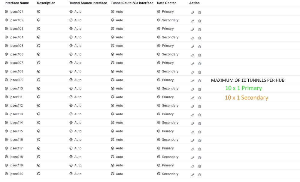
Note:If deploying multiple tunnels per router, ensure that the transport interface can sustain the aggregate bandwidth of all active tunnels combined. For example, if two tunnels are expected to carry up to 1 Gbps each, the transport link must support at least 2 Gbps of throughput.
Once the tunnels are configured, proceed with the BGP configuration.
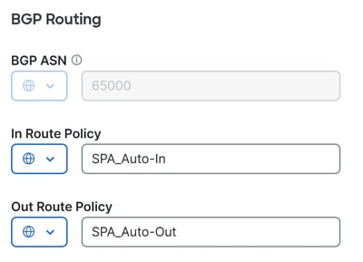
BGP Routing
BGP ASN: Specify AS number for the SD-WAN hub. The AS 64512 is reserved for Secure Access and can not be used. For more information about BGP, see In Route Policy: The system automatically creates this inbound route policy with a deny all statement to prevent routing issues. It must be manually modified through a CLI Add-On Template to allow/deny the appropriate routes.Out Route Policy: The system create this outbound route policy with a deny all statement to avoid routing problems. It must be manually edited through a CLI Add-On Template to allow/deny the appropriate routes.

Warning: Starting November 2025, all newly created Secure Access organizations use the public ASN 32644 by default for BGP peering in network tunnel groups. Existing organizations established prior to November 2025 continue to use the private ASN 64512 that was previously reserved for Secure Access BGP peers. If the private AS number 64512 is assigned to a device on your network, it not be able to peer with a network tunnel group configured for Peer (Secure Access) BGP AS 64512.
The next BGP and route-map configuration is automatically created for every BGP neighbor after you Deploy the new policy in your Policy Group.
route-map SPA_Auto-In deny 65534
 description Default Deny Configured from Secure Private Application Access feature
route-map SPA_Auto-Out deny 65534
 description Default Deny Configured from Secure Private Application Access feature

R104#sh run | s r b
router bgp 65000
bgp log-neighbor-changes
!
address-family ipv4 vrf 10
 neighbor 169.254.0.3 remote-as 64512
 neighbor 169.254.0.3 activate
 neighbor 169.254.0.3 send-community both
 neighbor 169.254.0.3 route-map SPA_Auto-In in
 neighbor 169.254.0.3 route-map SPA_Auto-Out out
 ...
 maximum-paths 32
exit-address-family
After this, click Save and proceed with the policy deployment to bring the tunnels up.
- Click on
Configuration > Policy Groups
- Choose under your
Policy > Secure Service Edge > Secure Private Application Access and click on the recent profile created for SPA.
- Click
Deploy to finalize
To verify inSecure Access, perform the next steps:
- Click on
Connect> Network Connections
TUNNEL ESTABLISHMENT
Configure Routing
Navigate to Configure > Configuration Groups
- Click on your
Configuration Group and Create/Edit your CLI Add-on Profile
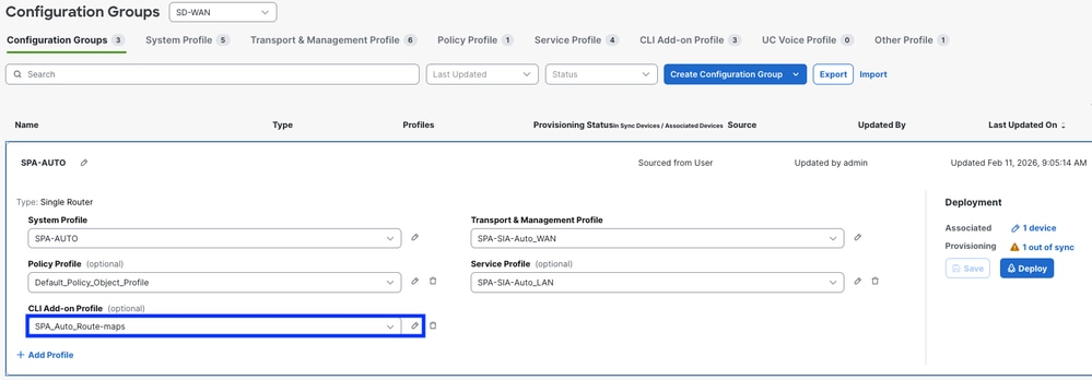
To allow BGP routes exchange, use the previously configured In Route Policy and Out Route Policy. You can find a basic example for the CLI Add-On route configuration. This template provides a starting point and must be customized as needed:
ip bgp-community new-format
ip prefix-list ALL-ROUTES seq 5 permit 0.0.0.0/0 le 32

route-map SPA_Auto-In permit 10
match ip address prefix-list ALL-ROUTES
route-map SPA_Auto-In deny 65534
description Default Deny Configured from Secure Private Application Access feature

route-map SPA_Auto-Out permit 10
match ip address prefix-list ALL-ROUTES
description Default Deny Configured from Secure Private Application Access feature
route-map SPA_Auto-Out deny 65534
description Default Deny Configured from Secure Private Application Access feature

router bgp 65000
bgp log-neighbor-changes
!
address-family ipv4 vrf 10
network 172.16.104.0 mask 255.255.255.0
Warning: Careful planning is required when defining the networks permitted in and out through BGP route-maps. Permitting all routes, as shown in the example above, can introduce unintended routing behavior. For optimal deployment, explicitly specify only the necessary networks in your route-maps to ensure controlled and predictable routing outcomes
Now you can proceed to Deploy the changes
To verify if BGP routes are received inSecure Access, check the next steps:
- Click on
Connect> Network Connections > Network Tunnel Groups and select the NTG name
ROUTING ESTABLISHMENT
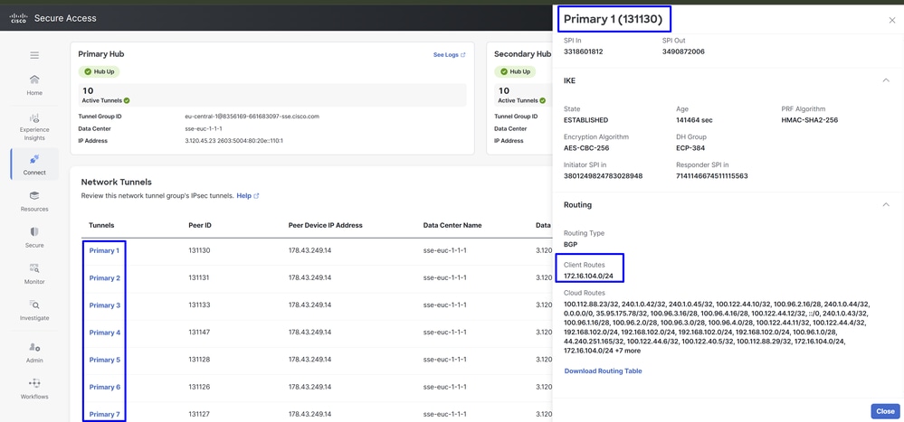
Note: In this example, the corporate user subnet 172.16.104.0/24 is advertised to Secure Access through BGP. This allows proper routing between Catalyst SD-WAN and the SSE environment.
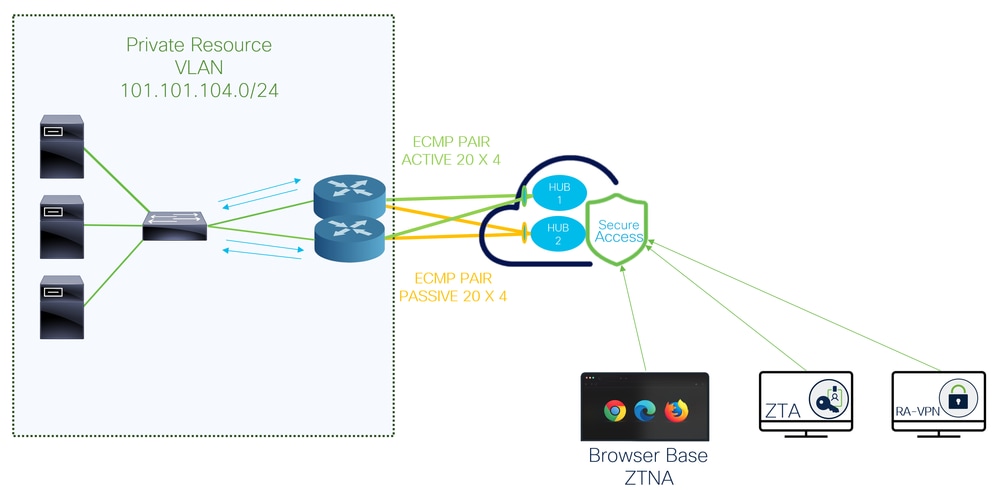
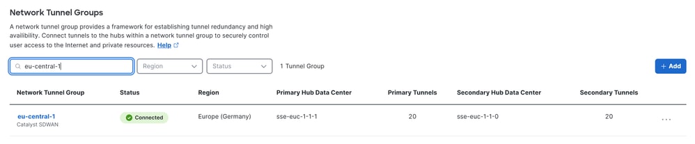
The same policy can be applied to both WAN edges in the Catalyst SD-WAN hubs, resulting in 20 active tunnels and 20 standby tunnels. The total number of tunnels depends on how many are configured on each edge. Any router connected to both Secure Access hubs (Hub 1 and Hub 2) forms an ECMP pair across all established tunnels.
For example, if Catalyst SD-WAN Edge 1 has 10 tunnels and Catalyst SD-WAN Edge 2 has 10 tunnels, Secure Access forms ECMP across the 20 active tunnels. The same behavior applies to the secondary SSE hub.
Verify
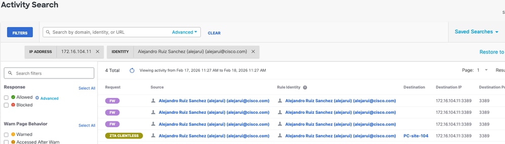
in order to verify if the traffic is going through Cisco Secure Access, navigate to Eventsor Activity Search or Network-Wide Path Insightsand filter by your tunnel identity:
Secure Access - Activity Search
Navigate to Monitor>Activity Search :
Secure Access - Events
Navigate to Monitor>Events:
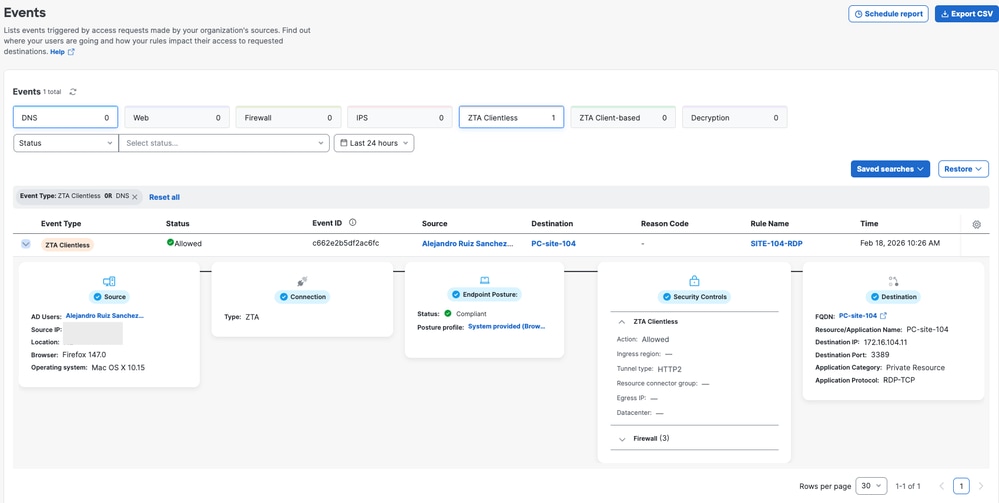
Note: Be sure you have your default policy with logging enabled, by default is disabled.
Catalyst SD-WAN Manager - Network-Wide Path Insights
Navigate to Catalyst SD-WAN Manager:
- Click on
Tools> Network-Wide Path Insights
- Click on
New Trace
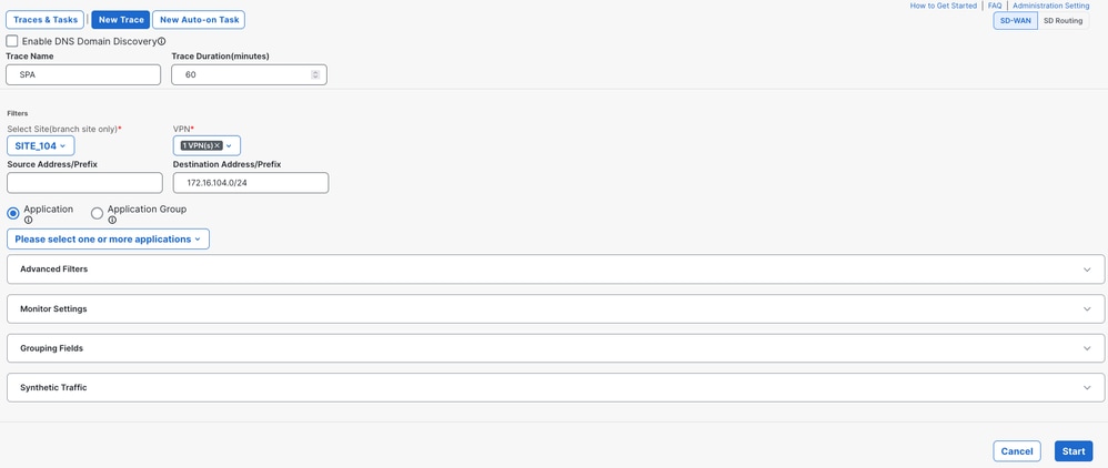
VPN: Choose the VPN ID where the private resource is locatedSource/Destination Address: (Optional) Enter the IP or leave it on blanck to capture all the traffic filtered based on Siteand VPNchoosen
Start the trace
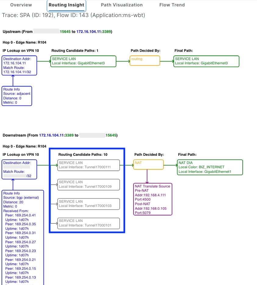
Locate the traffic flow and click View on the Insights column
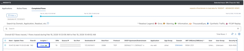
The routing Insights column display the candidate paths and display the IPSec tunnels to Secure Access
Related Information
 Feedback