Introduction
This document describes how to configure Secure Access with SD-WAN Automated Tunnels for Secure Internet Access.
Background Information
As organizations increasingly adopt cloud-based applications and support distributed workforces, network architectures must evolve to provide secure, reliable, and scalable access to resources. Secure Access Service Edge (SASE) is a framework that converges networking and security into a single cloud-delivered service, combining SD-WAN capabilities with advanced security functions such as Secure Web Gateway (SWG), Cloud Access Security Broker (CASB), DNS-layer security, Zero Trust Network Access (ZTNA) or integrated VPN for secure remote access.
Integrating Cisco Secure Access with SD-WAN through automated tunnels enables organizations to route internet traffic securely and efficiently. SD-WAN provides intelligent path selection and optimized connectivity across distributed locations, while Cisco Secure Access ensures that all traffic is inspected and protected according to corporate security policies before reaching the internet.
By automating tunnel configuration between SD-WAN devices and Secure Access, organizations can simplify deployment, improve scalability, and ensure consistent security enforcement for users-no matter where they are located. This integration is a key component of a modern SASE architecture, enabling secure internet access for branch offices, remote sites, and mobile users.
Network Diagram
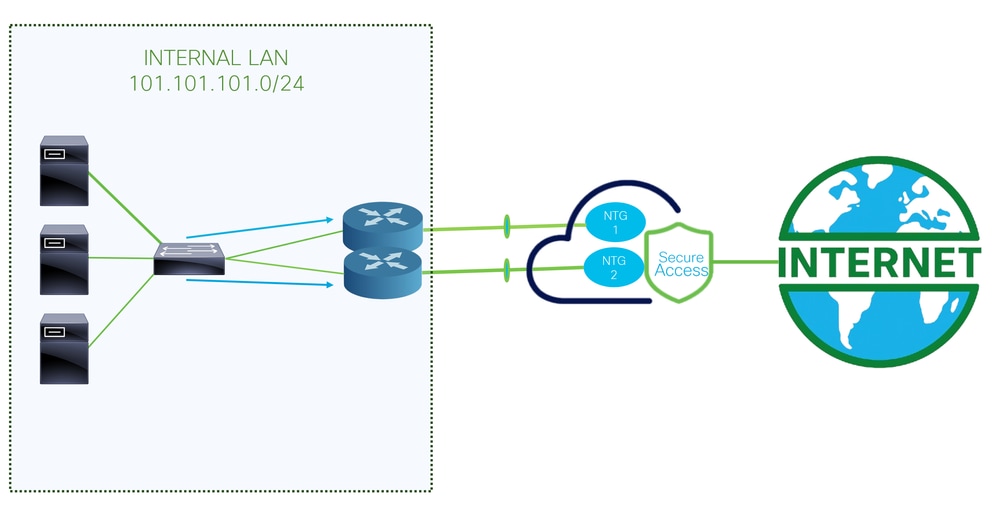
This is the architecture used for this configuration example. As you can see, there are two edge routers:
If you choose to deploy the policies to two different devices, an NTG is configured for each router, and NAT is enabled on the Secure Access side. This allows both routers to send traffic from the same source through the tunnels. Normally, this is not permitted; however, enabling the NAT option for these tunnels allows two edge routers to send traffic originating from the same source address.
Prerequisites
Requirements
- Secure Access Knowledge
- Cisco Catalyst SD-WAN Manager Release 20.15.1 and Cisco IOS XE Catalyst SD-WAN Release 17.15.1 or later
- Intermediate knowledge of routing and switching
- ECMP Knowledge
- VPN Knowledge
Components Used
- Secure Access Tenant
- Catalyst SD-WAN Manager Release 20.18.1 and Cisco IOS XE Catalyst SD-WAN Release 17.18.1
- Catalyst SD-WAN Manager
The information in this document was created from the devices in a specific lab environment. All of the devices used in this document started with a cleared (default) configuration. If your network is live, ensure that you understand the potential impact of any command.
Configure
Secure Access Configuration
API Creation
In order to create the automated tunnels with Secure Access check the next steps:
Navigate to Secure Access Dashboard.
- Click on
Admin > API Keys
- Click on
Add
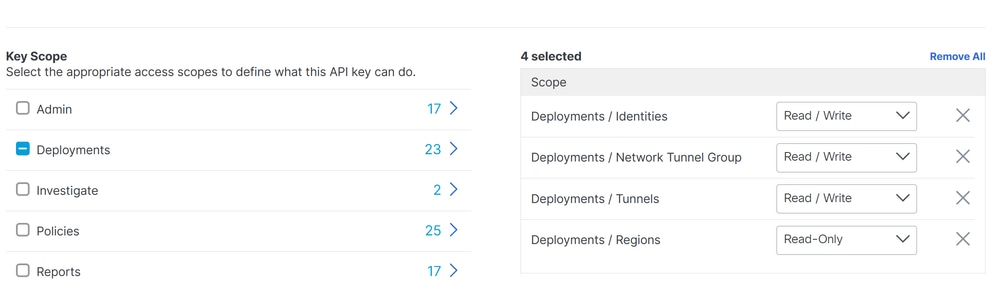
- Choose the next options:
Deployments / Network Tunnel Group: Read/WritteDeployments / Tunnels: Read/WritteDeployments / Regions: Read-OnlyDeployments / Identities: Read-WritteExpiry Date: Never Expire
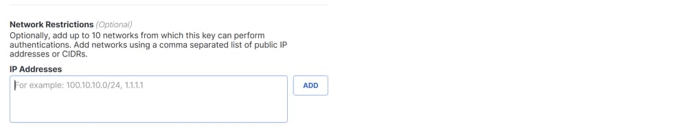


Note: Optionally, add up to 10 networks from which this key can perform authentications. Add networks using a comma separated list of public IP addresses or CIDRs.
- Click
CREATE KEY to finalize the creation of the API Key and Key Secret.


Caution: Copy them before you click ACCEPT AND CLOSE; otherwise, you need to create them again and delete the ones that were not copied.
Then to finalize click ACCEPT AND CLOSE.
SD-WAN Configuration
API Integration
Navigate to Catalyst SD-WAN Manager:
- Click on
Administration >Settings > Cloud Credentials
- Then click on
Cloud Provider Credentials and enable Cisco SSEand fill the API and Organtiazation Settings
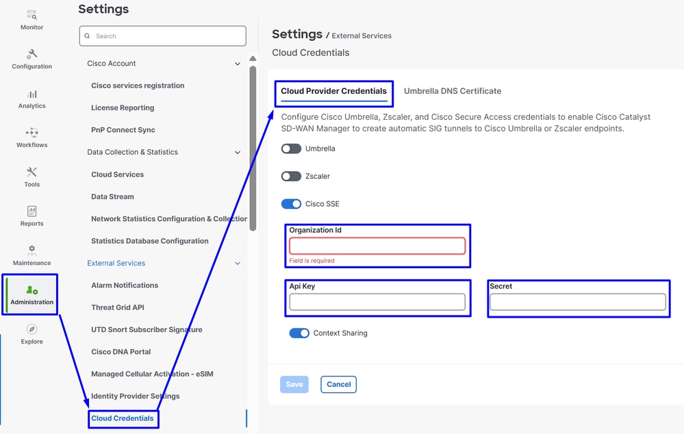
Then after that click on the Save button.
Note: Before you proceed with the next steps, you need to be sure that the SD-WAN Manager and the Catalyst SD-WAN Edges have DNS resolution and internet access.
To check if the DNS-Lookup is enabled please navigate to:
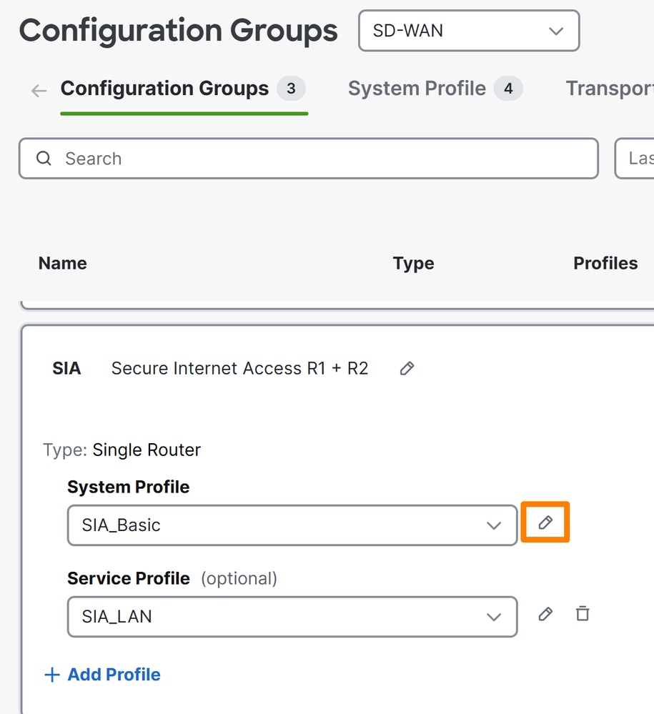
- Click on Configuration > Configuration Groups
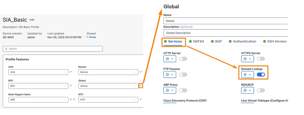
- Click on the profile of your Edge Devices and edit the System Profile
- Then Edit the Global option and be sure the option Domain Resolution is enabled
Configure Policy Group
Navigate to Configuration > Policy Groups:
- Click on
Secure Internet Gateway / Secure Service Edge > Add Secure Internet Access
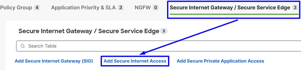
Note: In releases lower than 20.18 this option is called Add Secure Service Edge (SSE)
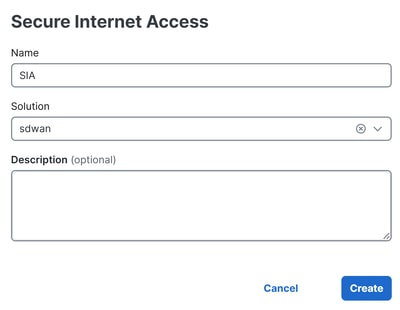
- Configure a name, solution and click on
Create
The next configurations allow you to create the tunnels after you deploy the configuration in your Catalyst SD-WAN Edges:
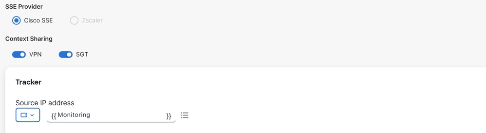
SSE Provider: SSEContext Sharing: Choose VPN or/and SGT depends of your needsTracker
Source IP Address: Choose Device Specific (This permit you to modify it per device and identify the use case for it in the deployment stage)
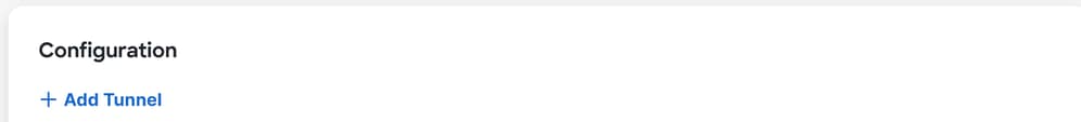
Under the Configuration step you set up the tunnels:
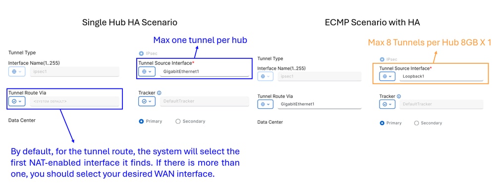
Single Hub HA Scenario: In this scenario, you can configure high availability using one NTG as active and another as passive, with a maximum throughput of 1Gbps per NTGECMP Scenario with HA: In this scenario, you can configure up to 8 tunnels per hub, supporting a total of up to 16 tunnels per NTG. This setup allows for higher throughput across the tunnels
Note: If your network interfaces have a throughput greater than 1Gbps and you require scalability, you must use loopback interfaces. Otherwise, you can use standard interfaces on your device. This is to enable ECMP from Secure Access side.

Warning: If you want to configure loopback interfaces for an ECMP scenario, you must first set up the loopback interfaces in Configuration Groups > Transport & Management Profile, under the policy that you use in your router.
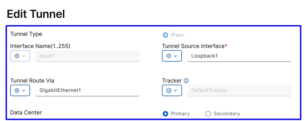
Interface Name: ipsec1, ipsec2, ipsec3 and so onTunnel Source Interface: Choose Loopback Interfaces or specific one from where you stablish the tunnelTunnel Route Via: If you choose Loopback, you need to select the physical interface from which you want to route the traffic. If you do not select Loopback, this option appeared grayed out, and use the first NAT enabled interface the system founds. If there is more than one, you must select your desired WAN interfaceData Center: This means to which Hub in Secure Access you stablish the connection
The next part of the tunnel configuration you configure the tunnels with the best practices provided by Cisco.
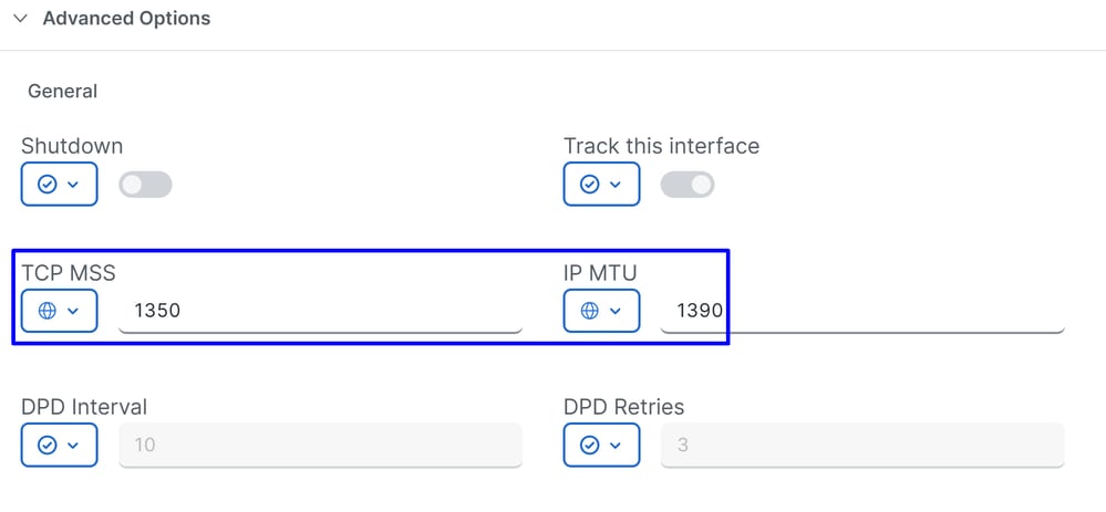

TCP MSS: 1350IP MTU: 1390IKE Diffie-Hellman Group: 20
After that you must configure the Secondary Tunnel pointing to the Secondary Datacenter.
SINGLE HUB HA SCENARIO
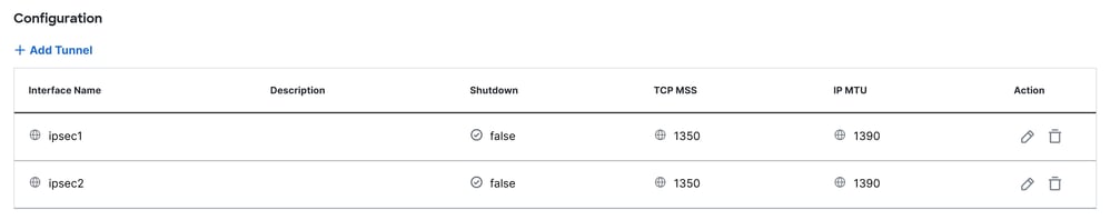
This is the final result when you use the normal scenario deployment.
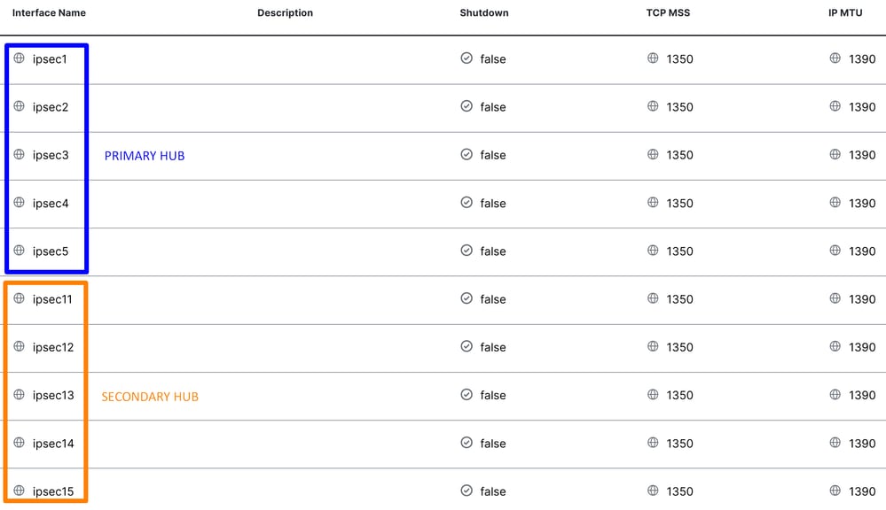
ECMP SCENARIO WITH HA
Then, you need to configure High Availability in the Secure Internet Policy.

Click on Add Interface Pair:
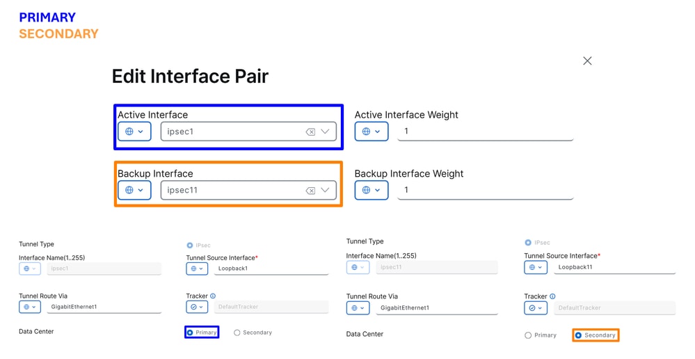
In this step, you need to configure the primary and secondary tunnel for each tunnel pair you are setting up. This means that each tunnel have its own backup. Remember, these tunnels were created as Primary and Secondary for this exact purpose.
"Active interface" refers to the Primary tunnel, while "Backup interface" refers to the Secondary tunnel:
Active Interface: PrimaryBackup Interface: Secondary
Warning: If this step is skipped, the tunnels do not come up, and no connection is established from the routers to Secure Access.
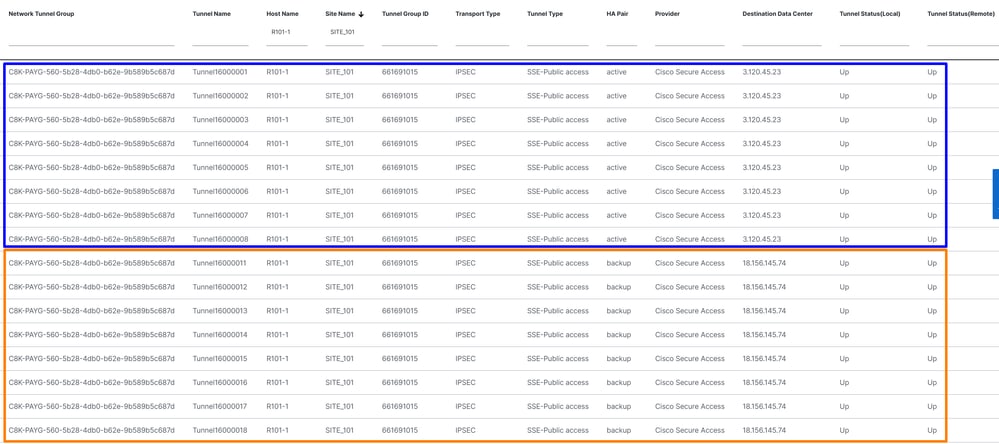
After High Availability is configured for the tunnels, the setup is displayed as shown in the image below. In the lab example used for this guide, five tunnels are shown in HA. The number of tunnels can be adjusted as needed.
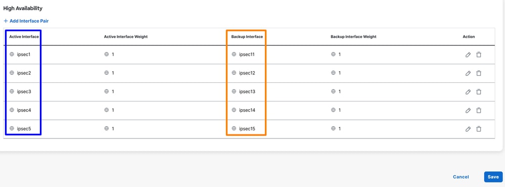
Note: A maximum of 8 tunnel pairs (16 tunnels: 8 primary and 8 secondary) can be configured in SD-WAN Catalyst vManage. Cisco Secure Access supports up to 10 tunnel pairs.
After this point, if everything is correctly configured, the tunnels appear as UP in the SD-WAN Manager and Secure Access.
To verify in SD-WAN, check he next steps:
- Click on
Monitor > Tunnels
- Then Click on
SIG/SSE Tunnels
And you are able to see the tunnels stablished to Cisco Secure Access UP or not.
To verify in Secure Access, check the next steps:
- Click on
Connect > Network Connections
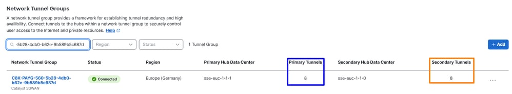
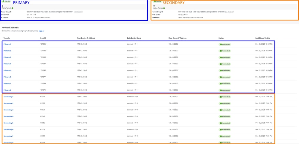
In a detailed view, click the name of the tunnel:
Afther this, you can move to the step, Create your Custom Bypass FQDN or APP in SD-WAN
Create your Custom Bypass FQDN or APP in SD-WAN (OPTIONAL)
There are special use cases where you need to create Application Bypass and FQDN or IP that you can apply to your routing policies:
Navigate to SD-WAN Manager portal:
- Click on
Configuration > Application Catalog > Applications
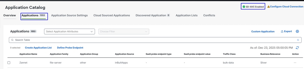

Tip: If running a version lower than 20.15, custom applications can be created under Policy Lists
Note: In order to have access to the Application Catalog you must enable SD-AVC.
- Click on
Custom Application

At this stage, a basic exclusion is configured using the Secure Client – Umbrella Module SWG FQDN:
ProxySecureAccess
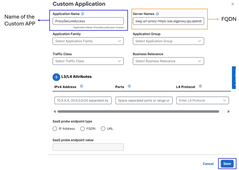
Server Name: Use the FQDN that you would like to bypass (In this example FQDN of SWG are configured)
- swg-url-proxy-https-sse.sigproxy.qq.opendns.com
- swg-url-proxy-https-ORGID.sseproxy.qq.opendns.com
- Click on
Save
Note: Change ORGID with your SSE organization number.
Next, a basic exclusion is created; in this case, the Umbrella DNS servers:
UmbrellaDNS
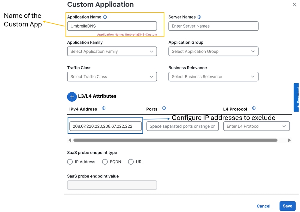
Now you can proceed with the configurations of the routing policies.
Routing your Traffic
In this step, you need to route internet traffic through the tunnels to protect it via Cisco Secure Access. In this case, you use a flexible routing policy that allows us to bypass certain traffic-helping to prevent sending unwanted traffic through Secure Access or to avoid potential bad practices.
First, let it define the two routing methods that can be used:
Configuration > Configuration Groups > Service Profile > Service Route: This method provides routing to Secure Access, but lacks flexibility.Configuration > Policy Groups > Application Priority & SLA: This method offers various routing options within SD-WAN and, most importantly, allows you to bypass specific traffic so it is not sent through Secure Access.
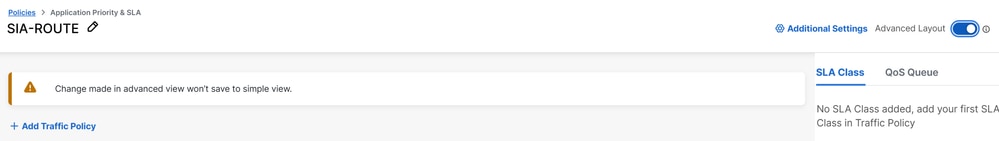
For flexibility and alignment with best practices, this configuration is used, Application Priority & SLA:
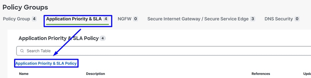
- Click on
Configuration > Policy Groups > Application Priority & SLA
- Then click on
Application Priority & SLA Policy
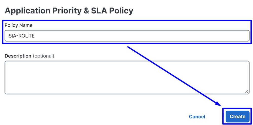
- Configure a Policy Name and click
Create
- Enable
Advanced Layout
- Click on
+ Add Traffic Policy
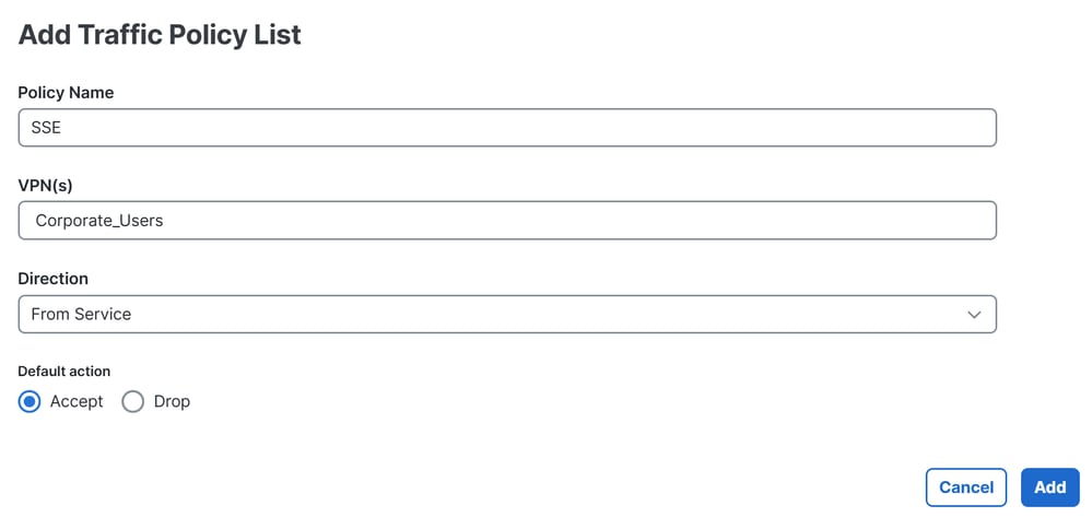
Policy Name: Name that adjust this to the purpose of this Traffic Policy ListVPN(s): Choose the Service VPN of user from where you route the trafficDirection: From ServiceDefault action: Accept
After that you are able to start the creation of the Traffic Policy:
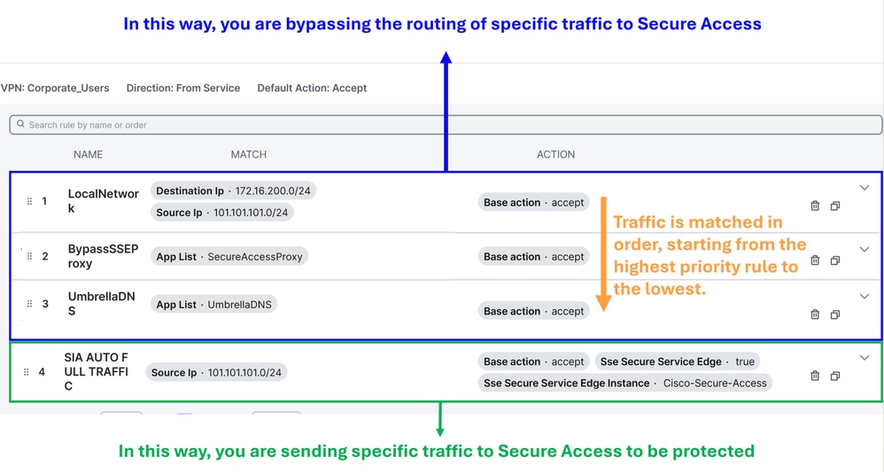
Local Network Policy (Optional): Source 101.101.101.0/24, Destination 172.16.200.0/24. This route prevents intra-network traffic from being sent to Cisco Secure Access. Typically, customers do not do this, as internal routing is usually handled by the distribution router in SD-WAN deployments. This configuration ensures that internal traffic between these subnets is not routed to Secure Access, depending on whether your scenario requires it (Optional, depends of your network enviroment)BypassSSEProxy (Optional): This policy prevents internal computers with the Cisco Umbrella module in Secure Client and SWG enabled from sending proxy traffic back to the cloud. Routing proxy traffic to the cloud again is not considered best practice.UmbrellaDNS (Best Practice): This policy prevents DNS queries destined for the internet from being sent through the tunnel. Sending DNS queries to Umbrella resolvers (208.67.222.222,208.67.220.220) via the tunnel is not recommended.SIA AUTO FULL TRAFFIC: This policy routes all traffic from the source 101.101.101.0/24 to the internet through the SSE tunnels you previously created, ensuring this traffic is protected in the cloud.
Verify
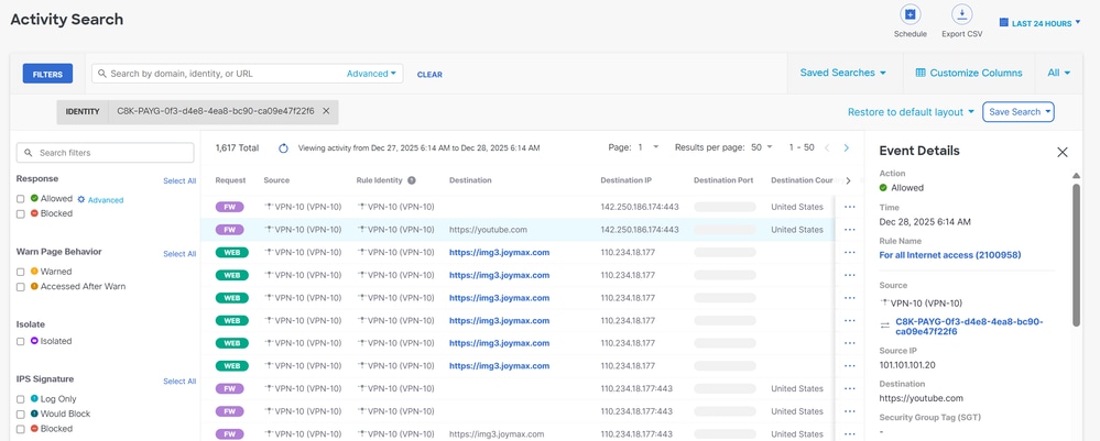
in order to verify if the traffic is flooding already through Cisco Secure Access, navigate to Events or Activity Search or Network-Wide Path Insights and filter by your tunnel identity:
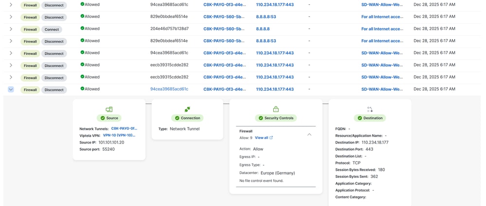
Secure Access - Activity Search
Navigate to Monitor > Activity Search:
Secure Access - Events
Navigate to Monitor > Events:
Note: Be sure you have your default policy with logging enabled, by default is disabled.
Catalyst SD-WAN Manager - Network-Wide Path Insights
Navigate to Catalyst SD-WAN Manager:
- Click on
Tools > Network-Wide Path Insights
- Click on
New Trace
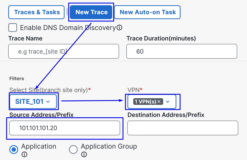
Site: Choose the site from where your traffic is eggressingVPN: Choose the VPN ID of your subnet from where your traffic is eggressingSource: Put the IP or let it on blanck to filter all the traffic filtered by the Site and VPN choosen
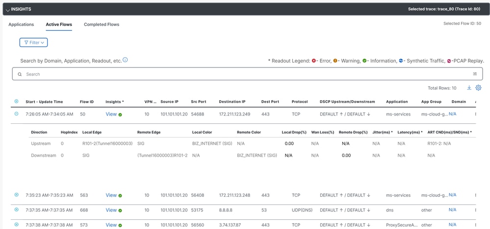
Then in Insights you are able to see the traffic flooding through the tunnels and the type of traffic going to Secure Access:
Related Information
 Feedback