Introduction
This document describes how to install and deploy Cisco FirePOWER software on a Cisco Unified Computing System E Series (UCS-E) blade platform in Intrusion Detection System (IDS) mode. The configuration example that is described in this document is a supplement to the official user guide.
Prerequisites
Requirements
There are no specific requirements for this document.
Components Used
The information in this document is based on these software and hardware versions:
- Cisco Integrated Services Routers (ISR) XE image 3.14 or later
- Cisco Integrated Management Controller (CIMC) Version 2.3 or later
- Cisco FireSIGHT Management Center (FMC) Version 5.2 or later
- Cisco FirePOWER Virtual Device (NGIPSv) Version 5.2 or later
- VMware ESXi Version 5.0 or later
The information in this document was created from the devices in a specific lab environment. All of the devices used in this document started with a cleared (default) configuration. If your network is live, ensure that you understand the potential impact of any command.
Note: Before you upgrade the code to Version 3.14 or later, ensure that the system has sufficient memory, disk space, and a license for the upgrade. Refer to the Example 1: Copy the image to flash: from TFTP server section of the Access Routers Software Upgrade Procedures Cisco document in order to learn more about code upgrades.
Note: In order to upgrade the CIMC, BIOS, and other firmware components, you can use either the Cisco Host Upgrade Utility (HUU), or you can upgrade the firmware components manually. In order to learn more about the firmware upgrade, refer to the Upgrading the Firmware on Cisco UCS E-Series Servers section of the Host Upgrade Utility User Guide for Cisco UCS E-Series Servers and the Cisco UCS E-Series Network Compute Engine.
Background Information
This section provides information about the supported hardware platforms, licenses, and limitations in regards to the components and procedures that are described in this document.
Supported Hardware Platforms
This section lists the supported hardware platforms for G2 and 4000 Series devices.
ISR G2 Devices with UCS-E Blades
These ISR G2 Series devices with UCS-E Series blades are supported:
| Product |
Platform |
UCS-E Model |
| Cisco 2900 Series ISR |
2911 |
UCS-E 120/140 single wide option |
| 2921 |
UCS-E 120/140/160/180 single or double wide option |
| 2951 |
UCS-E 120/140/160 single or double wide option |
| Cisco 3900 Series ISR |
3925 |
UCS-E 120/140/160 single and double wide option or 180 double wide |
| 3925E |
UCS-E 120/140/160 single and double wide option or 180 double wide |
| 3945 |
UCS-E 120/140/160 single and double wide option or 180 double wide |
| 3945E |
UCS-E 120/140/160 single and double wide option or 180 double wide |
ISR 4000 Devices with UCS-E Blades
These ISR 4000 Series devices with UCS-E Series blades are supported:
| Product |
Platform |
UCS-E Model |
| Cisco 4400 Series ISR |
4451 |
UCS-E 120/140/160 single and double wide option or 180 double wide |
| 4431 |
UCS-E Network Interface Module |
| Cisco 4300 Series ISR |
4351 |
UCS-E 120/140/160/180 single and double wide option or 180 double wide |
| 4331 |
UCS-E 120/140 single wide option |
| 4321 |
UCS-E Network Interface Module |
Licenses
The ISR must have a security K9 license, as well as an appx license, in order to enable the service.
Limitations
Here are the two limitations with regards to the information that is described in this document:
- Multicast is not supported
- Only 4,096 Bridge Domain Interfaces (BDI) are supported for each system
The BDIs do not support these features:
- Bidirectional Forwarding Detection (BFD) protocol
- Netflow
- Quality of Service (QoS)
- Network-Based Application Recognition (NBAR) or Advanced Video Coding (AVC)
- Zone Based Firewall (ZBF)
- Cryptographic VPNs
- Multiprotocol Label Switching (MPLS)
- Point-to-Point Protocol (PPP) over Ethernet (PPPoE)
Note: For a BDI, the Maximum Transmission Unit (MTU) size can be configured with any value between 1,500 and 9,216 bytes.
Configure
This section describes how to configure the components that are involved with this deployment.
Network Diagram
The configuration that is described in this document uses this network topology:
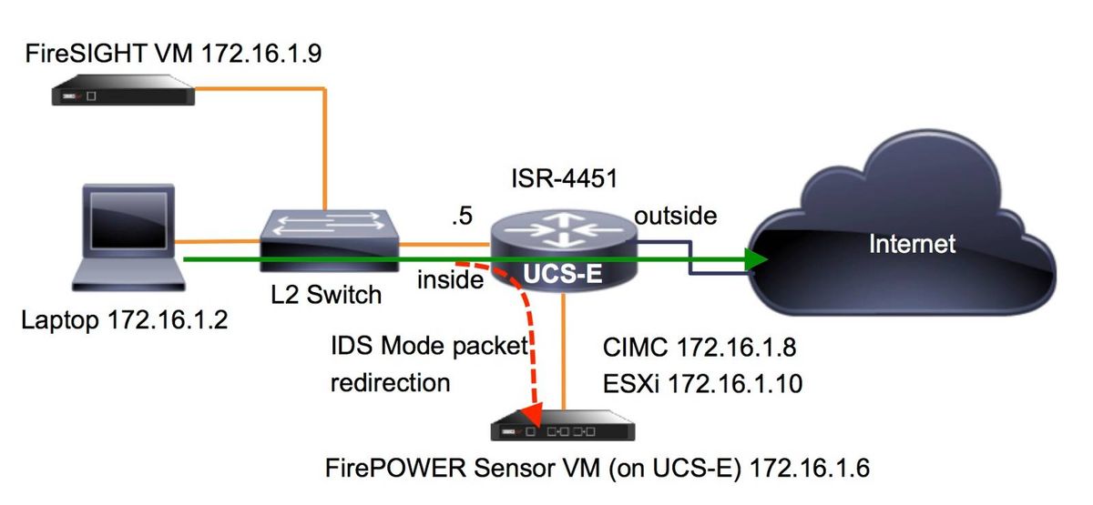
Workflow for FirePOWER Services on UCS-E
Here is the workflow for FirePOWER services that run on a UCS-E:
- The data-plane pushes traffic for inspection out from the BDI/UCS-E interface (works for G2 and G3 Series devices).
- The Cisco IOS®-XE CLI activates packet redirection for analysis (options for all interfaces or per-interface).
- The sensor CLI setup startup script simplifies the configuration.
Configure CIMC
This section describes how to configure the CIMC.
Connect to CIMC
There are multiple ways to connect to the CIMC. In this example, the connection to the CIMC is completed via a dedicated management port. Ensure that you connect the M port (dedicated) to the network with the use of an Ethernet cable. Once connected, run the hw-module subslot command from the router prompt:
ISR-4451#hw-module subslot 2/0 session imc

IMC ACK: UCSE session successful for IMC
Establishing session connect to subslot 2/0
To exit, type ^a^q

picocom v1.4

port is        : /dev/ttyDASH1
flowcontrol    : none
baudrate is    : 9600
parity is      : none
databits are   : 8
escape is      : C-a
noinit is      : no
noreset is     : no
nolock is      : yes
send_cmd is    : ascii_xfr -s -v -l10
receive_cmd is : rz -vv

Terminal ready
Tip 1: In order to exit, run ^a^q.
Tip 2: Default username is admin and password <password>. Password reset process is described here: https://www.cisco.com/c/en/us/td/docs/unified_computing/ucs/e/3-1-1/gs/guide/b_Getting_Started_Guide/b_3_x_Getting_Started_Guide_appendix_01011.html#GUID-73551F9A-4C79-4692-838A-F99C80E20A28
Configure CIMC
Use this information in order to complete the configuration of the CIMC:
Unknown# scope cimc
Unknown /cimc # scope network
Unknown /cimc/network # set dhcp-enabled no
Unknown /cimc/network *# set dns-use-dhcp no
Unknown /cimc/network *# set mode dedicated
Unknown /cimc/network *# set v4-addr 172.16.1.8
Unknown /cimc/network *# set v4-netmask 255.255.255.0
Unknown /cimc/network *# set v4-gateway 172.16.1.1
Unknown /cimc/network *# set preferred-dns-server 64.102.6.247
Unknown /cimc/network *# set hostname 4451-UCS-E
Unknown /cimc/network *# commit
Caution: Enure that you run the commit command in order to save the changes.
Note: The mode is set to dedicated when the management port is used.
Run the show detail command in order to verify the detail settings:
4451-UCS-E /cimc/network # show detail
  Network Setting:
  IPv4 Address: 172.16.1.8
  IPv4 Netmask: 255.255.255.0
  IPv4 Gateway: 172.16.1.1
  DHCP Enabled: no
  Obtain DNS Server by DHCP: no
  Preferred DNS: 64.102.6.247
  Alternate DNS: 0.0.0.0
  VLAN Enabled: no
  VLAN ID: 1
  VLAN Priority: 0
  Hostname: 4451-UCS-E
  MAC Address: E0:2F:6D:E0:F8:8A
  NIC Mode: dedicated
  NIC Redundancy: none
  NIC Interface: console
4451-UCS-E /cimc/network #
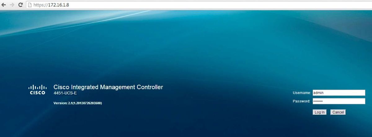
Launch the web interface of the CIMC from a browser with the default username and password as shown in the image. The default username and password are:
- Username: admin
- Password: <password>
Install ESXi
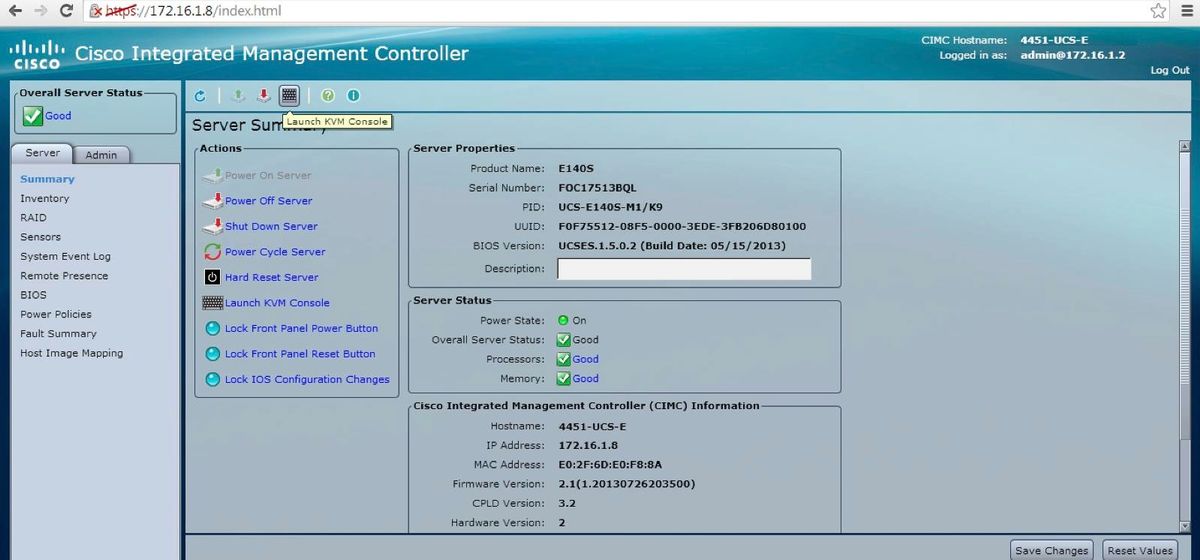
After you log into the user interface of the CIMC, you are able to view a page similar to that shown in this image. Click the Launch KVM Console icon, click add image, and then map the ESXi ISO as the virtual media:
Click the Virtual Media tab, and then click Add Image in order to map the virtual media as shown in the image.
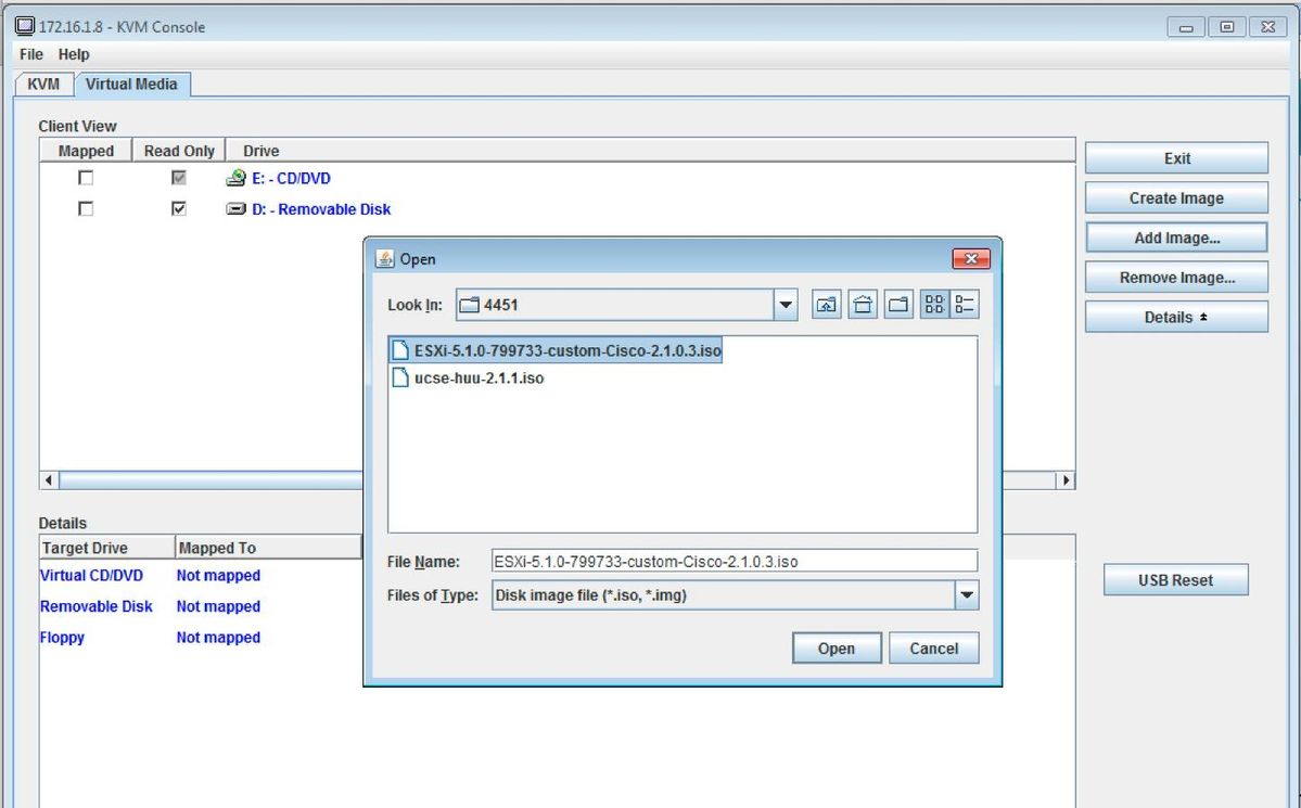
After the virtual media is mapped, click Power Cycle Server from the CIMC home page in order to power-cycle the UCS-E. The ESXi setup launches from the virtual media. Complete the ESXi install.
Note: Record the ESXi IP address, Username, and Password for future reference.
Install vSphere Client
This section describes how to install the vSphere client.
Download vSphere Client
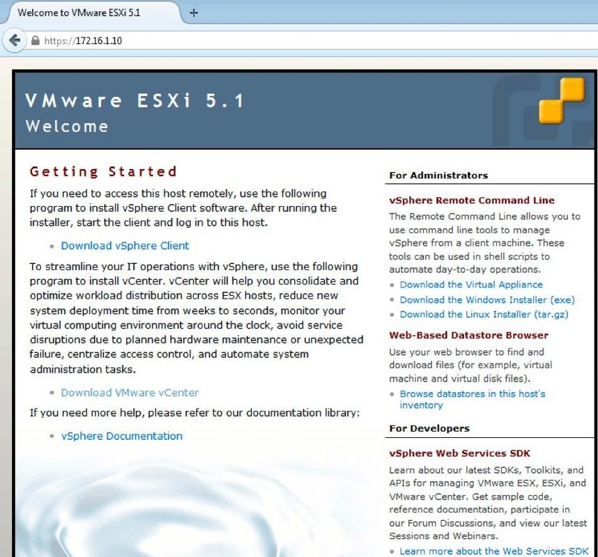
Launch ESXi and use the Download VSphere Client link in order to download the vSphere client. Install it on your computer.
Launch vSphere Client
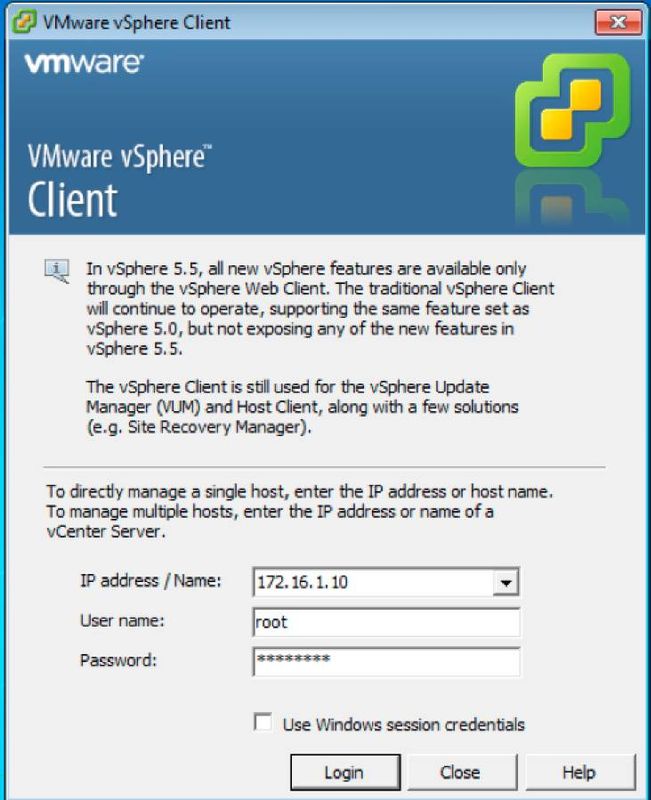
Launch the vSphere Client from your computer. Log in with the username and password that you created during installation and as shown in the image:
Deploy FireSIGHT Management Center and FirePOWER Devices
Complete the procedures that are described in the Deployment of FireSIGHT Management Center on VMware ESXi Cisco document in order to deploy a FireSIGHT Management Center on the ESXi.
Note: The process that is used in order to deploy a FirePOWER NGIPSv device is similar to the process that is used in order to deploy a Management Center.
Interfaces
On the Dual-Wide UCS-E, there are four interfaces:
- The highest MAC address interface is Gi3 on the front panel
- The second highest MAC address interface is Gi2 on the front panel
- The last two that appear are the internal interfaces
On the Single-Wide UCS-E, there are three interfaces:
- The highest MAC address interface is Gi2 on the front panel
- The last two that appear are the internal interfaces
Both of the UCS-E interfaces on the ISR4K are trunk ports.
The UCS-E 120S and 140S have three Network Adaptor plus Management Ports:
- The vmnic0 is mapped to UCSEx/0/0 on the router backplane
- The vmnic1 is mapped to UCSEx/0/1 on the router backplane
- The vmnic2 is mapped to the UCS-E front plane GE2 interface
- The front-panel management (M) port can only be used for the CIMC.
The UCS-E 140D, 160D, and 180D have four Network Adaptors:
- The vmnic0 is mapped to UCSEx/0/0 on the router backplane.
- The vmnic1 is mapped to UCSEx/0/1 on the router backplane.
- The vmnic2 is mapped to the UCS-E front plane GE2 interface.
- The vminc3 is mapped to the UCS-E front plane GE3 interface.
- The front-panel management (M) port can only be used for the CIMC.
vSwitch Interfaces on ESXi
The vSwitch0 on the ESXi is the management interface through which the ESXi, FireSIGHT Management Center, and the FirePOWER NGIPSv device communicate to the network. Click Properties for the vSwitch1 (SF-Inside) and the vSwitch2 (SF-Outside) in order to make any changes.
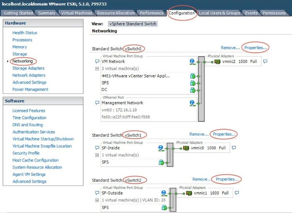
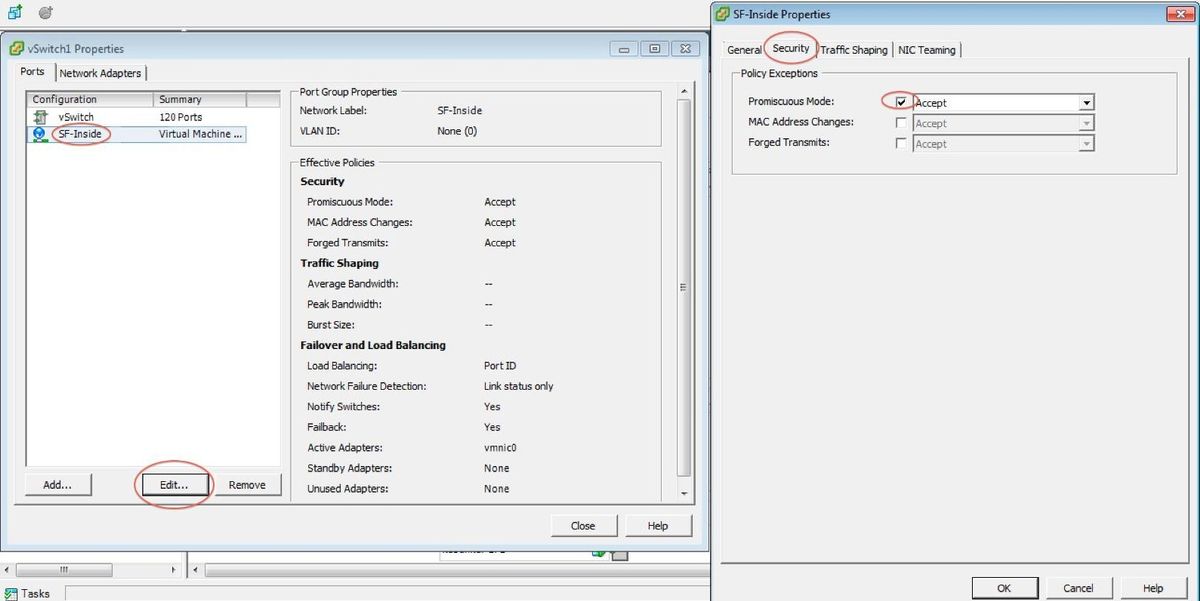
This image shows the properties of the vSwitch1 (you must complete the same steps for the vSwitch2):
Note: Ensure that the VLAN ID is configured to 4095 for NGIPSv, this is required according to NGIPSv document: http://www.cisco.com/c/en/us/td/docs/security/firepower/60/quick_start/ngips_virtual/NGIPSv-quick/install-ngipsv.html
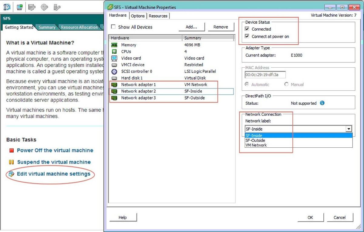
The vSwtich configuration on the ESXi is complete. Now you must verify the interface settings:
- Navigate to the virtual machine for the FirePOWER device.
- Click Edit virtual machine settings.
- Verify all of the three network adapters.
- Ensure that they are properly chosen, as shown in the image here:
Register FirePOWER Device with FireSIGHT Management Center
Complete the procedures that are described in the Cisco document in order to register a FirePOWER device with a FireSIGHT Management Center.
Redirect and Verify Traffic
Use this section in order to confirm that your configuration works properly.
This section describes how to redirect traffic and how to verify the packets.
Redirect Traffic from ISR to Sensor on UCS-E
Use this information in order to redirect the traffic:
interface GigabitEthernet0/0/1
 ip address dhcp
 negotiation auto
!
interface ucse2/0/0
 no ip address
 no negotiation auto
 switchport mode trunk
 no mop enabled
 no mop sysid
 service instance 1 ethernet
  encapsulation untagged
  bridge-domain 1
!
interface BDI1
 ip unnumbered GigabitEthernet0/0/1
end
!
utd
 mode ids-global
 ids redirect interface BDI1
Note: If you currently run Version 3.16.1 or later, run the utd engine advanced command instead of the utd command.
Verify Packet Redirection
From the ISR console, run this command in order to verify whether the packet counters increment:
cisco-ISR4451#  show plat hardware qfp active feature utd stats

Drop Statistics:
 Stats were all zero
General Statistics:
Pkts Entered Policy                                                        6
Pkts Entered Divert                                                        6
Pkts Entered Recycle Path                                                  6
Pkts already diverted                                                      6
Pkts replicated                                                            6
Pkt already inspected, policy check skipped                                6
Pkt set up for diversion                                                   6
Verify
You can run these show commands in order to verify that your configuration works properly:
- show plat software utd global
- show plat software utd interfaces
- show plat software utd rp active global
- show plat software utd fp active global
- show plat hardware qfp active feature utd stats
- show platform hardware qfp active feature utd
Troubleshoot
This section provides information you can use in order to troubleshoot your configuration.
You can run these debug commands in order to troubleshoot your configuration:
- debug platform condition feature utd controlplane
- debug platform condition feature utd dataplane submode
Related Information

 Feedback