Overview
This document provides troubleshooting information for Cisco UCS E-Series Servers (E-Series Servers) and the Cisco UCS E-Series Network Compute Engine (NCE).
Documentation is sometimes updated after original publication; therefore, review the documentation on Cisco.com for any updates.
Link to Product Documentation
For links to the all Cisco UCS E-Series Servers and the Cisco UCS E-Series Network Compute Engine documents, see: Documentation Guide for Cisco UCS E-Series Servers
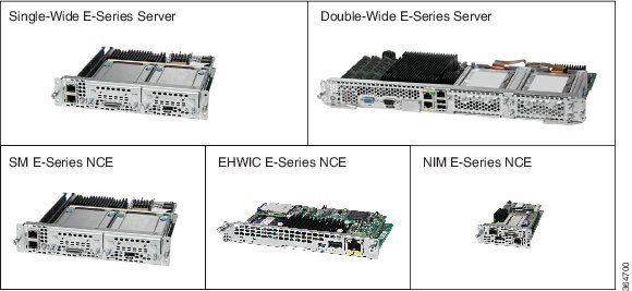
Types of E-Series Servers and NCEs
-
Single-wide E-Series Servers
-
Double-wide E-Series Servers
-
SM E-Series NCE
-
EHWIC E-Series NCE
-
NIM E-Series NCE
The following M1 E-Series Servers are supported:
- UCS-E140S-M1—Single-wide E-Series Server, 4-cores CPU, 1.0-GHz clock speed
- UCS-E140D-M1—Double-wide E-Series Server, 4-cores CPU, 2.0-GHz clock speed
- UCS-E160D-M1—Double-wide E-Series Server, 6-cores CPU, 1.8-GHz clock speed
- UCS-E140DP-M1—Double-wide E-Series Server, 4-cores CPU, with PCIe, 2.0-GHz clock speed
- UCS-E160DP-M1—Double-wide E-Series Server, 6-cores CPU, with PCIe, 1.8-GHz clock speed
The following M2 E-Series Servers and SM E-Series NCE are supported:
- UCS-EN120S-M2—SM E-Series NCE, 2-cores CPU, 2.0-GHz clock speed
- UCS-E140S-M2—Single-wide E-Series Server, 4-cores CPU, 1.8-GHz clock speed
- UCS-E160D-M2—Double-wide E-Series Server, 6-cores CPU, 2.0-GHz clock speed
- UCS-E180D-M2—Double-wide E-Series Server, 8-cores CPU, 1.8-GHz clock speed
The following M3 E-Series Servers are supported:
- UCS-E160S-M3—Single-wide E-Series Server, 6-cores CPU, 2.0-GHz clock speed
-
UCS-E180D-M3—Double-wide E-Series Server, 8-cores CPU, 1.5-GHz clock speed
-
UCS-E1120D-M3—Double-wide E-Series Server, 12-cores CPU, 1.6-GHz clock speed
 Note |
The M1, M2, and M3 E-Series Servers naming terminology indicates different generations of Intel processors within the respective servers. |
The following EHWIC E-Series NCE is supported:
- UCS-EN120E—EHWIC E-Series NCE, 2-cores CPU, 1.7-GHz clock speed
The following NIM E-Series NCE is supported:
- UCS-EN140N-M2—NIM E-Series NCE, 4-cores CPU, 1.7-GHz clock speed
General Troubleshooting
Cannot Access the E-Series Server or NCE
See the “Troubleshooting E-Series Server or NCE Access Issues” section in the “Firmware Management” chapter in the CLI Configuration Guide for Cisco UCS E-Series Servers and the Cisco UCS E-Series Network Compute Engine Integrated Management Controller, Release 3.2,x
CIMC Hangs
To resolve this problem, do the following:
- Use IPMI to reboot CIMC. If using IPMI does not resolve the problem, power cycle the E-Series Server.
- Verify that there is an SD card in the SD0 card slot. The SD card in the SD0 card slot contains the CIMC software and should always be present.
Note |
SD card is applicable to M1 and M2 servers. M3 servers have a dedicated SSD flash disk based on eMMC technology. This eMMC storage is not a user replaceable component. This replaces the SD card functionality that was used on M1 and M2 servers. |
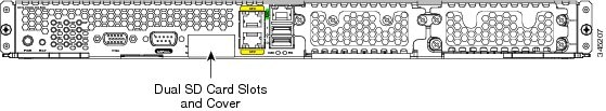
The below figure shows the location of the SD0 card slot in a single-wide E-Series Server.

The below figure shows the location of the dual SD card slots in a double-wide E-Series Server.
Note |
The SD0 card is the lower card, located in the bottom SD card slot. |
- Power down the E-Series Server to check whether the SD card has come
out of the slot. If it has, reinsert the SD card. Do the following:
- If the E-Series Server is installed in a Cisco 3900 series router, use the hw-module sm slot oir-stop command to power down the server, reinsert the SD card, and then use the hw-module sm slot oir-start command to start the server.
- If the E-Series Server is installed in a Cisco 2900 series router, power cycle the router.
Note |
Do not remove the SD card when the system is in operation. |
CIMC Upgrade Fails When Upgrading from Version 2.2 to 3.1.x
If you are running CIMC version 2.2.x, first upgrade to version 2.3.2 and then upgrade to 3.1.x.
If you have already upgraded to CIMC version 3.1.x, type *** to get into the recovery shell and then install the image 3.1.x from the recovery shell.
Cannot Download the Host Image
To resolve this problem, verify the following:
- The FTP server on which you want to download the host image is running.
- The FTP server path to the image files is correct.
Cannot Power on the E-Series Server
To resolve this problem, clear the server's BIOS CMOS memory using the CIMC GUI or the CIMC CLI:
Clearing the BIOS CMOS Using the CIMC GUI
Before You Begin
- Log into the CIMC GUI as a user with admin privileges.
- Power off the server.
SUMMARY STEPS
- In the Navigation pane, click the Server tab.
- On the Server tab, click BIOS.
- In the Actions area, click Clear BIOS CMOS.
- In the confirmation window, click OK.
DETAILED STEPS
| Step 1 |
In the Navigation pane, click the Server tab. |
| Step 2 |
On the Server tab, click BIOS. |
| Step 3 |
In the Actions area, click Clear BIOS CMOS. |
| Step 4 |
In the confirmation window, click OK. |
Clearing the BIOS CMOS Using the CIMC CLI
SUMMARY STEPS
- Enter the BIOS command mode. Use the scope bios command:
- Clear the BIOS CMOS memory. Use the clear cmos command:
- At the confirmation prompt, enter y to confirm
DETAILED STEPS
| Step 1 |
Enter the BIOS command mode. Use the scope bios command: Example: |
| Step 2 |
Clear the BIOS CMOS memory. Use the clear cmos command: Example: |
| Step 3 |
At the confirmation prompt, enter y to confirm Example: |
Cannot Configure Power Restore Policy on ISR 4K Platforms
Due to hardware differences between the ISR G2 and ISR 4K platforms, the BIOS setting for Power Restore Policy is not applicable on ISR 4K platforms. Instead, the CIMC automatically enacts a “Restore Last State” policy on ISR 4K.
Note |
On ISR 4K platforms, Power Restore Policy settings will be configurable in CIMC beginning with the Release 3.1.3. On ISR G2 platforms, Power Restore Policy settings are still configured through the BIOS settings in CIMC. |
Boot Order Configuration is not Saved after a Server Reboot
Make sure that you configure boot order through the CIMC, and save the changes (“commit” in CLI or “save changes” in GUI). Do not configure boot order through the BIOS setup (<F2>) menu. If you configure boot order through the BIOS setup, the CIMC configuration will overwrite the boot order configuration.
Recovering From a Corrupted CIMC Firmware Image
See the “Troubleshooting E-Series Server or NCE Access Issues” section in the “Firmware Management” chapter in the CLI Configuration Guide for Cisco UCS E-Series Servers and the Cisco UCS E-Series Network Compute Engine Integrated Management Controller, Release 3.2,x.
Recovering From a Faulty SD Drive
See the “Troubleshooting E-Series Server or NCE Access Issues” section in the “Firmware Management” chapter in the CLI Configuration Guide for Cisco UCS E-Series Servers and the Cisco UCS E-Series Network Compute Engine Integrated Management Controller, Release 3.2,x.
Recovering From a Corrupted File System
See the “Troubleshooting E-Series Server or NCE Access Issues” section in the “Firmware Management” chapter in the CLI Configuration Guide for Cisco UCS E-Series Servers and the Cisco UCS E-Series Network Compute Engine Integrated Management Controller, Release 3.2,x.
Verifying and Upgrading to the Latest Firmware Image
Use the Cisco Host Upgrade Utility to verify and upgrade to the latest firmware image. See the Host Upgrade Utility Guide for Cisco UCS E-Series Servers and the Cisco UCS E-Series Network Compute Engine.
ESXi 7.0 (Original Release) Not Supported on UCSE
Up to ESXi 6.7U3, tg3 driver is supported and UCSE internal NICs are detected. ESXi 7.0 (original release) does not support tg3 driver, and therefore does not detect internal NIC on UCSE M3.
Workaround: ESXi 7.0U1is supported on UCSE modules.VMNIC Interface Ordering does not Start with Lowest MAC Address
Workaround for ESXi versions 6.7U1,6.7U2,6.0U2, and 6.0U3:
To make VMNIC interface ordering start with the lowest MAC address, follow these steps:
-
Enable Shell and SSH in ESXi.
-
SSH into ESXi.
-
Use esxcli network nic list command to display VMNIC number and its corresponding MAC address.
-
Use localcli --plugin-dir /usr/lib/vmware/esxcli/int/ deviceInternal alias list command to display the Bus address and VMNIC number mappings.
-
Use localcli command to remap VMNIC number to Bus address that has the lowest MAC address.
-
Reboot ESXi.
-
SSH into ESXi and verify the changes.
This example shows how to display VMNIC number and its MAC address:
~ # esxcli network nic list
Name    PCI Device     Driver  Link  Speed  Duplex  MAC Address         MTU  Description
------  -------------  ------  ----  -----  ------  -----------------  ----  -------------------------------------------------------
vmnic0  0000:04:00.0  ixgben  Up            Up            1000  Full    00:f6:63:b9:65:d6  1500  Intel(R) Ethernet Connection X552/X557-AT 10GBASE-T
vmnic1  0000:04:00.1  ixgben  Up            Up            1000  Full    00:f6:63:b9:65:d7  1500  Intel(R) Ethernet Connection X552/X557-AT 10GBASE-T
vmnic2  0000:09:00.0  tg3     Up            Up            1000  Full    00:f6:63:b9:65:d4  1500  Broadcom Corporation NetXtreme BCM5719 Gigabit Ethernet
vmnic3  0000:09:00.1  tg3     Up            Up            1000  Full    00:f6:63:b9:65:d5  1500  Broadcom Corporation NetXtreme BCM5719 Gigabit Ethernet
This example shows how to display Bus address and VMNIC name mapping:
~ # localcli --plugin-dir /usr/lib/vmware/esxcli/int/ deviceInternal alias list
Bus type  Bus address          Alias
------------------------------------
pci       p0000:09:00.1        vmnic3
pci       p0000:09:00.0        vmnic2
pci       p0000:07:00.0        vmhba0
pci       p0000:04:00.1        vmnic1
pci       p0000:04:00.0        vmnic0
logical   pci#p0000:04:00.1#0  vmnic1
logical   pci#p0000:04:00.0#0  vmnic0
logical   pci#p0000:07:00.0#0  vmhba0
This example shows how to remap VMNIC number to Bus address that has the lowest MAC address:
[root@localhost:~] localcli --plugin-dir /usr/lib/vmware/esxcli/int/ deviceInternal alias store --alias vmnic0 --bus-address p0000:09:00.0 --bus-type pci
[root@localhost:~]  localcli --plugin-dir /usr/lib/vmware/esxcli/int/ deviceInternal alias store --alias vmnic1 --bus-address p0000:09:00.1 --bus-type pci
[root@localhost:~]  localcli --plugin-dir /usr/lib/vmware/esxcli/int/ deviceInternal alias store --alias vmnic2 --bus-address p0000:04:00.0 --bus-type pci
[root@localhost:~] localcli --plugin-dir /usr/lib/vmware/esxcli/int/ deviceInternal alias store --alias vmnic3 --bus-address p0000:04:00.1 --bus-type pci
[root@localhost:~]  localcli --plugin-dir /usr/lib/vmware/esxcli/int/ deviceInternal alias store --alias vmnic2 --bus-address pci#p0000:04:00.0#0 --bus-type logical
[root@localhost:~] localcli --plugin-dir /usr/lib/vmware/esxcli/int/ deviceInternal alias store --alias vmnic3 --bus-address pci#p0000:04:00.1#0 --bus-type logical
[root@localhost:~] reboot
After a reboot, the VMNIC interface number begins with the lowest MAC address. This example shows the output after the reboot:
~ # esxcli network nic list
Name    PCI Device     Driver  Link  Speed  Duplex  MAC Address         MTU  Description
vmnic0  0000:09:00.0  tg3     Up            Up            1000  Full    00:f6:63:b9:65:d4  1500  Broadcom Corporation NetXtreme BCM5719 Gigabit Ethernet
vmnic1  0000:09:00.1  tg3     Up            Up            1000  Full    00:f6:63:b9:65:d5  1500  Broadcom Corporation NetXtreme BCM5719 Gigabit Ethernet
vmnic2  0000:04:00.0  ixgben  Up            Up            1000  Full    00:f6:63:b9:65:d6  1500  Intel(R) Ethernet Connection X552/X557-AT 10GBASE-T
vmnic3  0000:04:00.1  ixgben  Up            Up            1000  Full    00:f6:63:b9:65:d7  1500  Intel(R) Ethernet Connection X552/X557-AT 10GBASE-T
Workaround for ESXi versions 6.5,6.5U1, and 6.5U2:
To make VMNIC interface ordering start with the lowest MAC address, follow these steps:
-
Enable Shell and SSH in ESXi.
-
SSH into ESXi.
-
Use esxcli network nic list command to display VMNIC number and its corresponding MAC address.
-
Use localcli --plugin-dir /usr/lib/vmware/esxcli/int/ deviceInternal alias list command to display the Bus address and VMNIC number mappings.
-
Use localcli command to remap VMNIC number to Bus address that has the lowest MAC address.
-
Reboot ESXi.
-
SSH into ESXi and verify the changes.
This example shows how to display VMNIC number and its MAC address:
~ # esxcli network nic list
Name    PCI Device     Driver  Link  Speed  Duplex  MAC Address         MTU  Description
------  -------------  ------  ----  -----  ------  -----------------  ----  -------------------------------------------------------
vmnic0  0000:004:00.0  ixgbe   Up     1000  Full    a8:9d:21:fc:61:12  1500  Intel(R) Ethernet Connection X552/X557-AT 10GBASE-T
vmnic1  0000:004:00.1  ixgbe   Up     1000  Full    a8:9d:21:fc:61:13  1500  Intel(R) Ethernet Connection X552/X557-AT 10GBASE-T
vmnic2  0000:008:00.0  tg3     Up     1000  Full    a8:9d:21:fc:61:10  1500  Broadcom Corporation NetXtreme BCM5719 Gigabit Ethernet
vmnic3  0000:008:00.1  tg3     Up     1000  Full    a8:9d:21:fc:61:11  1500  Broadcom Corporation NetXtreme BCM5719 Gigabit Ethernet
This example shows how to display Bus address and VMNIC name mapping:
~ # localcli --plugin-dir /usr/lib/vmware/esxcli/int/ deviceInternal alias list
Bus type  Bus address          Alias
------------------------------------
pci       p0000:06:00.0        vmhba0
pci       p0000:08:00.0        vmnic2
pci       p0000:08:00.1        vmnic3
pci       p0000:04:00.1        vmnic1
pci       p0000:04:00.0        vmnic0
logical   pci#p0000:06:00.0#0  vmhba0
This example shows how to remap VMNIC number to Bus address that has the lowest MAC address:
~ # localcli --plugin-dir /usr/lib/vmware/esxcli/int/ deviceInternal alias store --alias vmnic0 --bus-address p0000:08:00.0 --bus-type pci
~ # localcli --plugin-dir /usr/lib/vmware/esxcli/int/ deviceInternal alias store --alias vmnic1 --bus-address p0000:08:00.1 --bus-type pci
~ # localcli --plugin-dir /usr/lib/vmware/esxcli/int/ deviceInternal alias store --alias vmnic2 --bus-address p0000:04:00.0 --bus-type pci
~ # localcli --plugin-dir /usr/lib/vmware/esxcli/int/ deviceInternal alias store --alias vmnic3 --bus-address p0000:04:00.1 --bus-type pci
~ # reboot
After a reboot, the VMNIC interface number begins with the lowest MAC address. This example shows the output after the reboot:
~ # esxcli network nic list
Name    PCI Device     Driver  Link  Speed  Duplex  MAC Address         MTU  Description
------  -------------  ------  ----  -----  ------  -----------------  ----  -------------------------------------------------------
vmnic0  0000:008:00.0  tg3     Up     1000  Full    a8:9d:21:fc:61:10  1500  Broadcom Corporation NetXtreme BCM5719 Gigabit Ethernet
vmnic1  0000:008:00.1  tg3     Up     1000  Full    a8:9d:21:fc:61:11  1500  Broadcom Corporation NetXtreme BCM5719 Gigabit Ethernet
vmnic2  0000:004:00.0  ixgbe   Up     1000  Full    a8:9d:21:fc:61:12  1500  Intel(R) Ethernet Connection X552/X557-AT 10GBASE-T
vmnic3  0000:004:00.1  ixgbe   Up     1000  Full    a8:9d:21:fc:61:13  1500  Intel(R) Ethernet Connection X552/X557-AT 10GBASE-T
~ # localcli --plugin-dir /usr/lib/vmware/esxcli/int/ deviceInternal alias list
Bus type  Bus address          Alias
------------------------------------
pci       p0000:06:00.0        vmhba0
pci       p0000:08:00.0        vmnic0
pci       p0000:08:00.1        vmnic1
pci       p0000:04:00.1        vmnic3
pci       p0000:04:00.0        vmnic2
logical   pci#p0000:06:00.0#0  vmhba0
~ #
To Enable ixgbe Driver
After you install or upgrade the ESXi version to specific builds of 6.5 and 6.7 in the UCS-E M3 modules, either the Intel 10Gig NICs (external port) disappear or they remain in downstate. To fix this issue, follow these steps:
# esxcfg-module-d ixgben
# esxcfg-module-e ixgbe
# Reboot the host
UCS-E Module Booting Issues
Normal Working Scenario
4351-2002#show platform
Chassis type: ISR4351/K9

Slot      Type                State                 Insert time (ago)
--------- ------------------- --------------------- -----------------
0         ISR4351/K9          ok                    4w0d
 0/0      ISR4351-3x1GE       ok                    4w0d
 0/1      UCS-EN140N-M2/K9    ok                    4w0d
1         ISR4351/K9          ok                    4w0d
 1/0      UCS-E160D-M2/K9     ok                    4w0d
2         ISR4351/K9          ok                    4w0d
R0        ISR4351/K9          ok, active            4w0d
F0        ISR4351/K9          ok, active            4w0d
P0        PWR-4450-AC         ok                    4w0d
P2        ACS-4450-FANASSY    ok                    4w0d

Slot      CPLD Version        Firmware Version
--------- ------------------- ---------------------------------------
0         14080523            16.12(2r)
1         14080523            16.12(2r)
2         14080523            16.12(2r)
R0        14080523            16.12(2r)
F0        14080523            16.12(2r)
Failed Scenarios
Scenario 1:
Frame errors, which are specific to UCS-E M3 double-wide modules does not display online.
Note |
The below failure error may not be seen immediately during bootup, but can be seen later too. |
*May 9 04:12:55.963: %SPA_OIR-6-ONLINECARD: SPA (UCS-E180D-M3/K9) online in subslot 1/0
*May 9 04:12:57.913: %LINK-3-UPDOWN: Interface ucse1/0/0, changed state to up
*May 9 04:12:58.914: %LINEPROTO-5-UPDOWN: Line protocol on Interface ucse1/0/0, changed state to up
*May 9 04:13:26.608: %IOMD-3-MODULE_MESSAGE: R0/0: iomd: UCS-E180D-M3/K9[1/0] NGIO control packet loss detected: Router not initiating module recovery. Control plane andSolution:
Fix available in 3.2.11.1 CIMC version
Scenario 2:
The UCS-E M3 double-wide modules momentarily go offline for under 20 secs once in a while, it is a false alarm. These modules come back online on its own.
Nov 2 13:53:33.265 CDT: %SPA_OIR-3-HW_SIGNAL_DEASSERTED: subslot 1/0 <<<<<<<<<<<<<<<<<<<<<<<<<<<<<<<<<<<
Nov 2 13:53:33.275 CDT: %LINK-3-UPDOWN: Interface BDI2, changed state to down
Nov 2 13:53:34.275 CDT: %LINEPROTO-5-UPDOWN: Line protocol on Interface BDI2, changed state to down
Nov 2 13:53:36.265 CDT: %LINEPROTO-5-UPDOWN: Line protocol on Interface ucse1/0/1, changed state to down
Nov 2 13:53:36.386 CDT: %LINEPROTO-5-UPDOWN: Line protocol on Interface Tunnel1, changed state to down
Nov 2 13:53:38.086 CDT: %APPNAV_CONTROLLER-4-SNG_UNAVAILABLE: APPNAV-CONTROLLER: Alarm #30001, Severity: Major
Nov 2 13:53:38.086 CDT: %APPNAV_CONTROLLER-4-SC_SN_UNREACHABLE: APPNAV-CONTROLLER: Alarm #29007, Severity: Major
Nov 2 13:53:38.265 CDT: %SPA_OIR-3-RECOVERY_RELOAD: subslot 1/0: Attempting recovery by reloading SPA
Nov 2 13:53:38.266 CDT: %SPA_OIR-6-OFFLINECARD: SPA (UCS-E180D-M2/K9) offline in subslot 1/0
Nov 2 13:53:46.502 CDT: %SPA_OIR-6-ONLINECARD: SPA (UCS-E180D-M2/K9) online in subslot 1/0 <<<<<<<<<<<<<<<<<<<<<<
Nov 2 13:53:48.451 CDT: %LINK-3-UPDOWN: Interface ucse1/0/0, changed state to up Nov 2 13:53:48.501 CDT: %LINK-3-UPDOWN: Interface ucse1/0/1, changed state to upSolution:
Fix available in IOS 16.9.4, it has been addressed through CSCvn20913 - UCSE modules have seen false SPA_OIR-3-HW_SIGNAL_DEASSERTED
Scenario 3:
CIMC reboots due to some errors, such as memory leak in CIMC software.
Jun 20 02:07:49.932 GMT: %SPA_OIR-3-HW_SIGNAL_DEASSERTED: subslot 3/0
Jun 20 02:07:51.931 GMT: %LINK-5-CHANGED: Interface ucse3/0/0, changed state to administratively down
Jun 20 02:07:52.932 GMT: %LINEPROTO-5-UPDOWN: Line protocol on Interface ucse3/0/0, changed state to down
Jun 20 02:07:54.932 GMT: %SPA_OIR-3-RECOVERY_RELOAD: subslot 3/0: Attempting recovery by reloading SPA
Jun 20 02:07:54.933 GMT: %SPA_OIR-6-OFFLINECARD: SPA (UCS-E1120D-M3/K9) offline in subslot 3/0
Jun 20 02:09:36.802 GMT: %SPA_OIR-6-ONLINECARD: SPA (UCS-E1120D-M3/K9) online in subslot 3/0
Jun 20 02:09:38.770 GMT: %LINK-3-UPDOWN: Interface ucse3/0/0, changed state to up
Jun 20 02:09:39.770 GMT: %LINEPROTO-5-UPDOWN: Line protocol on Interface ucse3/0/0, changed state to upSolution:
All known issues are addressed with the CIMC 3.2.9 release.
Scenario 4:
CIMC looses connectivity from IOS when the server finishes booting with NFVIS.
Solution:
Fix is available in NFVIS 4.1 release.
Verify the Functioning of the UCS-E M3 Double-Wide Modules
Device# test platform software tdl ping subslot 1/0 module endpoint 0
Type escape sequence to abort.
Sending 5, 100-byte TDL Echos to subslot 1/0, timeout is 1 seconds:
!!!!!
Success rate is 100 percent (5/5), round-trip min/avg/max = 10/16/24 ms
Module round-trip min/avg/max = 9/15/22 ms
VMware License Troubleshooting
Cannot Apply VMware FL-SRE-V-HOST License
This problem occurs if you are using more than 32 GB of RAM with VMware vSphere Hypervisor ™ 5.x. To resolve this problem, reduce the RAM to 32 GB or less, or upgrade your license to FL-SRE-V-HOSTVC.
Microsoft Windows Installation Troubleshooting
VMware Boots After Microsoft Windows Installation
This problem occurs if you had first installed VMware, and then installed Microsoft Windows. To resolve this problem, do the following:
- Change the state of the physical drive to JBOD. See the “Changing the Physical Drive State” section in the configuration guides for the version of the CIMC that you are using.
- Configure RAID to clear partitions. See the “Configuring RAID Using the CIMC GUI” section in the configuration guides for the version of the CIMC that you are using.
The configuration guides are available at: http://www.cisco.com/c/en/us/support/servers-unified-computing/ucs-e-series-servers/products-installation-and-configuration-guides-list.html.
Microsoft Windows Installation Displays VMware Partitions
During the Microsoft Windows installation, the “Where do you want to install Windows” dialog box appears (see figure below, which displays partitions that were previously created by VMware. This dialog box also displays the following warning message:
Warning: Windows Cannot be Installed to Disk x
 Partition x
To resolve this problem, clear the old partitions by clicking Drive options (advanced) , and then resume with the Microsoft Windows installation.

Host Login and CIMC Login Troubleshooting
Cannot Session into the E-Series Server (Host)
The ucse slot session host command does not allow you to log into the E-Series Server. To resolve this problem, do the following:
Procedure
SUMMARY STEPS
- Verify that the line speed value is 9600. Use the show line command to verify the line speed value:
- If the line speed value is correct, verify that the Baud rate value is 9.6K and the terminal type is compatible. Use the show detail command from /bios/server-management to verify the Baud rate and terminal type:
- Verify that the Enabled option in Serial over LAN (sol) is configured as no. Use the show detail command from /sol to verify the sol configuration:
DETAILED STEPS
| Step 1 |
Verify that the line speed value is 9600. Use the show line command to verify the line speed value: Example: |
| Step 2 |
If the line speed value is correct, verify that the Baud rate value is 9.6K and the terminal type is compatible. Use the show detail command from /bios/server-management to verify the Baud rate and terminal type: Example: |
| Step 3 |
Verify that the Enabled option in Serial over LAN (sol) is configured as no. Use the show detail command from /sol to verify the sol configuration: Example: |
Cannot Session into CIMC with Active Directory Authentication
This problem occurs if you did not provide your full domain name followed by your username. To resolve this problem, provide your full domain name followed by your username. For example:
CIMC login: cert.cisco.com\adadmin
Password:
PING 172.19.159.52 (172.19.159.52): 56 data bytes
64 bytes from 172.19.159.52: seq=0 ttl=128 time=0.000 ms
--- 172.19.159.52 ping statistics ---
1 packets transmitted, 1 packets received, 0% packet loss
round-trip min/avg/max = 0.000/0.000/0.000 ms
Determining Version Information
Determining the Cisco IOS Version Installed on the Router
Note |
The supported Cisco IOS software version on E-Series Servers is 15.2(4)M and later versions. For details, see the “Verifying the Router, E-Series Server, and Cisco IOS Software Version Compatibility” section in the getting started guide for the version of the CIMC that you are using. The getting started guides are available at: http://www.cisco.com/c/en/us/support/servers-unified-computing/ucs-e-series-servers/products-installation-guides-list.html. |
To determine the Cisco IOS version, use the show version or the show inventory command from the router:
Router> show version
Cisco CISCO3945-CHASSIS (revision 1.0) with C3900-SPE150/K9 with 1048576K/63488K bytes of memory.
1 cisco UCSE Module(s)
Router>
 show inventory
NAME: “UCSE Server Module on Slot 4", DESCR: “UCSE Server Module”
PID: UCS-E140D-M1/K9   , VID: V00 , SN: FOC16161F5E
Determining Information About the E-Series Server Through Diagnostics
To determine the type of E-Series Server that is installed in the router and in which slot it is installed, use the show diag command from the router:
Router>
 show diag
Slot 4:
UCSE Double Wide Module Port adapter, 2 ports
Port adapter is analyzed
Port adapter insertion time 4d18h ago
Product (FRU) Number     : UCS-E140D-M1/K9
Determining the Hardware Version of the E-Series Server or the NCE
You can determine the hardware version of the E-Series Server or the NCE from the CIMC GUI or from the CIMC CLI:
Determining the Hardware Version of the E-Series Server or the NCE from the CIMC GUI
SUMMARY STEPS
- In the Navigation pane, click the Server tab.
- On the Server tab, click Summary. The Server Summary page appears.
- In the Cisco Integrated Management Controller (CIMC) Information area, the hardware version of the E-Series Server is displayed in the CPLD Version and the Hardware Version fields.
DETAILED STEPS
| Step 1 |
In the Navigation pane, click the Server tab. |
| Step 2 |
On the Server tab, click Summary. The Server Summary page appears. |
| Step 3 |
In the Cisco Integrated Management Controller (CIMC) Information area, the hardware version of the E-Series Server is displayed in the CPLD Version and the Hardware Version fields. |
Determining the Hardware Version of the E-Series Server or the NCE from the CIMC CLI
Enter the following commands:
Server# scope cimc
Server/cimc # scope firmware

Server/cimc/firmware # show detail
 Firmware Image Information:
    Update Stage: NONE
    Update Progress: 100%
    Current FW Version: 3.2(3.20180516084909)
    FW Image 1 Version: 3.2(3.20180516084909)
    FW Image 1 State: RUNNING ACTIVATED
    FW Image 2 Version: 3.2(5.20180712134324)
    FW Image 2 State: BACKUP INACTIVATED
    Boot-loader Version: 3.2(3.20180516084909).36
    CPLD Version: 4.0
    Hardware Version: 2
Determining the BIOS Version Installed on the E-Series Server or the NCE
You can determine the BIOS version of the E-Series Server or the NCE from the CIMC GUI or from the CIMC CLI.
Determining the BIOS Version Installed on the E-Series Server or the NCE from the CIMC GUI
To determine the BIOS version of the E-Series Server, do the following from the CIMC GUI.
SUMMARY STEPS
- In the Navigation pane, click the Server tab.
- On the Server tab, click BIOS . The BIOS page appears.
- In the BIOS Properties area, the BIOS version is displayed in the Running Version field.
DETAILED STEPS
| Step 1 |
In the Navigation pane, click the Server tab. |
| Step 2 |
On the Server tab, click BIOS . The BIOS page appears. |
| Step 3 |
In the BIOS Properties area, the BIOS version is displayed in the Running Version field. |
Determining the BIOS Version Installed on the E-Series Server or the NCE from the CIMC CLI
Enter the following commands:
Server # scope bios
Server /bios # show detailBIOS:
    BIOS Version: "UCSEM3_2.4 (Build Date: 09/05/2017)"
    Boot Order: CDROM:Virtual-CD,HDD:RAID
    FW Update/Recovery Status: None, OK
    Active BIOS on next reboot: main
    UEFI Secure Boot: disabled
Determining the CIMC Version Installed on the E-Series Server or the NCE
You can determine the CIM version installed on the E-Series Server or the NCE from the CIMC GUI or from the CIMC CLI.
Determining the CIMC Version Installed on the E-Series Server or the NCE from the CIMC GUI
To determine the CIMC version of the E-Series Server, do the following from the CIMC GUI.
SUMMARY STEPS
- In the Navigation pane, click the Admin tab.
- On the Admin tab, click Firmware Management . The Firmware Management page appears.
- In the CIMC Firmware area, the CIMC version is displayed in the Running Version field.
DETAILED STEPS
| Step 1 |
In the Navigation pane, click the Admin tab. |
| Step 2 |
On the Admin tab, click Firmware Management . The Firmware Management page appears. |
| Step 3 |
In the CIMC Firmware area, the CIMC version is displayed in the Running Version field. |
Determining the CIMC Version Installed on the E-Series Server or the NCE from the CIMC CLI
Enter the following commands:
Server# scope cimc
Server/cimc # scope firmware

Server/cimc/firmware # show detail
 Firmware Image Information:
    Update Stage: NONE
    Update Progress: 100%
    Current FW Version: 3.2(3.20180516084909)
    FW Image 1 Version: 3.2(3.20180516084909)
    FW Image 1 State: RUNNING ACTIVATED
    FW Image 2 Version: 3.2(5.20180712134324)
    FW Image 2 State: BACKUP INACTIVATED
    Boot-loader Version: 3.2(3.20180516084909).36
    CPLD Version: 4.0
    Hardware Version: 2
Determining the LSI Firmware Version—Applicable on CIMC Release 1.x
To determine the LSI firmware version, do the following from the CIMC GUI.
Procedure
SUMMARY STEPS
- In the Navigation pane, click the Server tab.
- On the Server tab, click Inventory. The Inventory page appears.
- Click the Storage tab.
- In the Storage Adapters area, the LSI firmware information is displayed in the Firmware Package Build column.
DETAILED STEPS
| Step 1 |
In the Navigation pane, click the Server tab. |
| Step 2 |
On the Server tab, click Inventory. The Inventory page appears. |
| Step 3 |
Click the Storage tab. |
| Step 4 |
In the Storage Adapters area, the LSI firmware information is displayed in the Firmware Package Build column. |
Determining the LSI Firmware Version—Applicable on CIMC Release 2.x
Note |
This procedure is applicable to E-Series Servers and the SM E-Series NCE. This section is not applicable to the EHWIC E-Series NCE. |
To determine the LSI firmware version, do the following from the CIMC GUI.
Procedure
SUMMARY STEPS
- In the Navigation pane, click the Server tab.
- On the Server tab, click RAID. The Storage Cards page appears.
- In the Storage Adapters area, the LSI firmware information is displayed in the Firmware Package Build column.
DETAILED STEPS
| Step 1 |
In the Navigation pane, click the Server tab. |
| Step 2 |
On the Server tab, click RAID. The Storage Cards page appears. |
| Step 3 |
In the Storage Adapters area, the LSI firmware information is displayed in the Firmware Package Build column. |
Cisco IOS and CIMC CLI Configuration Troubleshooting
Cisco IOS Configurations Not Applied to CIMC
This problem occurs if Lock IOS Configuration Changes is enabled in CIMC. Use the CIMC GUI or the CIMC CLI to resolve this problem.
Enabling Cisco IOS Configuration Changes to Be Applied to CIMC Using the GUI
To enable Cisco IOS configuration changes to be applied to CIMC, do the following from the CIMC GUI.
Procedure
SUMMARY STEPS
- In the Navigation pane, click the Server tab.
- On the Server tab, click Summary. The Server Summary page appears.
- From the Server Summary page, click the Lock IOS Configuration Changes button to unlock it.
DETAILED STEPS
| Step 1 |
In the Navigation pane, click the Server tab. |
| Step 2 |
On the Server tab, click Summary. The Server Summary page appears. |
| Step 3 |
From the Server Summary page, click the Lock IOS Configuration Changes button to unlock it. |
Enabling Cisco IOS Configuration to Be Applied to CIMC Using the CLI
Use the set ios-lockout unlocked command to enable the Cisco IOS configuration changes to be applied to CIMC:
Server /chassis # set ios-lockout unlocked
Server /chassis *# commit
Server /chassis # show detail
Chassis:
    Power: off
    Power Button: unlocked
    IOS Lockout: unlocked
    Serial Number: FOC16161F5E
    Product Name: E140D
    PID : UCS-E140D-M1/K9
    UUID: 1255F7F0-0F16-0000-E5A5-05EAA6AF20B5
    Description:
Cannot View Latest Configuration Changes in CIMC
To resolve this problem, after making changes to the configuration, click Refresh .
Cannot Commit CIMC CLI Configuration Changes
This problem occurs under the following conditions:
- If you assigned a static IP address for CIMC, and then left the values of DHCP Enabled and DNS-use-DHCP as Yes . To resolve this problem, change the value to No , and then assign the static IP address:
Server /cimc/network # set dns-use-dhcp no
Server /cimc/network *# set dhcp-enabled no
Server /cimc/network *# set v4-addr 192.168.100.78

Server /cimc/network *# commit
- If you made configuration changes in one scope, and then tried to commit those changes from another scope.
The commit command must be used to commit changes that are made within the same scope. If you try to use the commit command to submit changes made in a different scope, an error message displays. To resolve this problem, redo and recommit the changes in the same scope.
LED, DIMM, Video Port, USB Port, and CD/DVD Troubleshooting
LED Color Displays Amber—Applicable to the E-Series Servers and the SM E-Series NCE
At run time or during server start-up, the post diagnostic tests check the CPU, DIMM, and HDD. If any failure occurs, the failure notifications are sent to the system event logs (SEL). You can view these notification in the SEL or in the output of the show tech-support command. When errors occur, an amber diagnostic LED displays next to the failed component. To resolve the DIMM and HDD problem, power down the E-Series Server or SM E-Series NCE, and then verify if the DIMMs and the hard drives are installed correctly.
Procedure
SUMMARY STEPS
- If the E-Series Server or SM E-Series NCE is installed into a 3900 series router, power off the server using the hw-module sm slot oir stop command; otherwise, power down the router.
- Remove the server.
- Reinsert the DIMMs or hard drives as appropriate.
- Reinsert the server into the router.
- If the router was powered down, power it on.
DETAILED STEPS
| Step 1 |
If the E-Series Server or SM E-Series NCE is installed into a 3900 series router, power off the server using the hw-module sm slot oir stop command; otherwise, power down the router. |
| Step 2 |
Remove the server. |
| Step 3 |
Reinsert the DIMMs or hard drives as appropriate. |
| Step 4 |
Reinsert the server into the router. |
| Step 5 |
If the router was powered down, power it on. |
DIMM Not Functioning
To resolve this problem, do the following:
-
Make sure that the DIMMs are installed and are of the same capacity. Do the following:
- In the Navigation pane, click the Server tab.
- On the Server tab, click Inventory. The Inventory page appears.
- Click the Memory tab. The Capacity column in the Memory Details area allows you to determine the capacity of the DIMMs and whether the DIMM is installed or not.
Verify that the value in the Capacity column for the DIMMs is the same.
If the DIMMs are installed, the Capacity column displays a numerical value; otherwise, it displays Not Installed .
-
Check whether there are memory related system event logs. Do the following:
- In the Navigation pane, click the Server tab.
- On the Server tab, click System Event Log. The System Event Log page appears.
- In the Description column, look for events that start with FRU_RAM xxx .
-
Check if the DIMM is supported on that server model.
- Single-Wide E-Series Server—Supports DDR3 1333MHz VLP UDIMM 1.5 V, 4 GB, and 8 GB
- Double-Wide E-Series Server—Supports DDR3 1333 MHz RDIMM 1.35 V, 4 GB, 8 GB and 16 GB
- Double-wide with PCIE support—Supports DDR3 1333 MHz RDIMM 1.35 V, 4 GB, 8 GB, and 16 GB
- EHWIC E-Series NCE—Supports DDR3 1333 MHz SODIMM, 4 GB, 8 GB, and 16GB
- Check if the DIMM is correctly installed in the server slot, otherwise, remove and reinstall the DIMM.
Front Panel Video Port Does Not Work—Applicable to the E-Series Servers and the SM E-Series NCE
This problem occurs if the Enable Local Server Video checkbox is not checked. To resolve this problem, do the following from the CIMC GUI.
Procedure
SUMMARY STEPS
- In the Navigation pane, click the Server tab.
- On the Server tab, click Remote Presence .
- In the Remote Presence pane, click the Virtual KVM tab.
- In the vKVM Properties area, check the Enable Local Server Video checkbox.
DETAILED STEPS
| Step 1 |
In the Navigation pane, click the Server tab. |
| Step 2 |
On the Server tab, click Remote Presence . |
| Step 3 |
In the Remote Presence pane, click the Virtual KVM tab. |
| Step 4 |
In the vKVM Properties area, check the Enable Local Server Video checkbox. |
Front Panel USB Port Does Not Work
The light on the device that is connected to the front panel USB port is off. This problem occurs if the USB Port in the USB BIOS Settings is not enabled. To resolve this problem, do the following from the CIMC GUI.
Procedure
SUMMARY STEPS
- In the Navigation pane, click the Server tab.
- On the Server tab, click BIOS .
- In the Actions area, click Configure BIOS . The Configure BIOS Parameters dialog box appears.
- In the Configure BIOS Parameters dialog box, click the Advanced tab.
- Scroll down until you reach the USB BIOS Settings area.
- Verify if the USB Port 0 and USB Port 1 are enabled. If the ports are disabled, enable them.
DETAILED STEPS
| Step 1 |
In the Navigation pane, click the Server tab. |
| Step 2 |
On the Server tab, click BIOS . |
| Step 3 |
In the Actions area, click Configure BIOS . The Configure BIOS Parameters dialog box appears. |
| Step 4 |
In the Configure BIOS Parameters dialog box, click the Advanced tab. |
| Step 5 |
Scroll down until you reach the USB BIOS Settings area. |
| Step 6 |
Verify if the USB Port 0 and USB Port 1 are enabled. If the ports are disabled, enable them. |
Cannot Boot from the External CD/DVD Device
To resolve this problem, do the following:
- Verify that the USB Port to which the CD/DVD device is connected to, is enabled. See Front Panel USB Port Does Not Work.
- Verify that the power current used by the CD/DVD device does not exceed 700mA. If it exceeds 700mA, the USB port to which the CD/DVD device is connected to, might not stay stable. The USB port might go on or off; or might get disabled. To resolve this problem, try connecting the device to an externally-powered USB hub.
- Make sure that the CD/DVD ROM device is configured as the first boot device in the boot order table. For procedure, See Configuring the Boot Order Using the BIOS Setup Menu.
- Reboot the E-Series Server.
Configuring the Boot Order Using the BIOS Setup Menu
Use this procedure if you want the server to boot from an external bootable device, such as an USB or an
external CD ROM drive that is directly connected to the E-Series Server. Do the following from the CIMC GUI.
Procedure
SUMMARY STEPS
- In the Navigation pane, click the Server tab.
- On the Server tab, click Summary .
- From the Actions area, click Launch KVM Console . The KVM Console opens in a separate window.
- From the Server Summary page, click Power Cycle Server to reboot the server.
- When prompted, press F2 during bootup to access the BIOS setup menu. The Aptio Setup Utility appears, which provides the BIOS setup menu option.
- Use the Right or Left arrow keys on your keyboard to select the Boot tab.
- Scroll down to the bottom of the page below the Boot Options Priority area. The following boot option priorities are listed:
- Use the Up or Down arrow keys on your keyboard to highlight the appropriate option.
- Press Enter to select the highlighted field.
- Choose the appropriate device as Boot Option 1.
- Press F4 to save changes and exit.
DETAILED STEPS
| Step 1 |
In the Navigation pane, click the Server tab. |
| Step 2 |
On the Server tab, click Summary . |
| Step 3 |
From the Actions area, click Launch KVM Console . The KVM Console opens in a separate window. |
| Step 4 |
From the Server Summary page, click Power Cycle Server to reboot the server. |
| Step 5 |
When prompted, press F2 during bootup to access the BIOS setup menu. The Aptio Setup Utility appears, which provides the BIOS setup menu option. |
| Step 6 |
Use the Right or Left arrow keys on your keyboard to select the Boot tab. |
| Step 7 |
Scroll down to the bottom of the page below the Boot Options Priority area. The following boot option priorities are listed:
|
| Step 8 |
Use the Up or Down arrow keys on your keyboard to highlight the appropriate option. |
| Step 9 |
Press Enter to select the highlighted field. |
| Step 10 |
Choose the appropriate device as Boot Option 1. |
| Step 11 |
Press F4 to save changes and exit. The Main tab of the BIOS setup displays the device that you configured as Boot Option 1. |
KVM Troubleshooting
Cannot Mount vMedia
This problem can occur if you have not enabled virtual media. To resolve this problem, do the following from the CIMC GUI.
Procedure
SUMMARY STEPS
- In the Navigation pane, click the Server tab.
- On the Server tab, click Remote Presence. The Remote Presence page appears.
- Click the Virtual Media tab, and in the Virtual Media Properties area, check the Enabled check box.
- If this does not solve the problem, do the following:
DETAILED STEPS
| Step 1 |
In the Navigation pane, click the Server tab. |
| Step 2 |
On the Server tab, click Remote Presence. The Remote Presence page appears. |
| Step 3 |
Click the Virtual Media tab, and in the Virtual Media Properties area, check the Enabled check box. |
| Step 4 |
If this does not solve the problem, do the following:
|
Cannot Launch vKVM—Error Message: Connection Failed
If you try to launch vKVM through Proxy, you get a Connection Failed error message. To resolve this problem, disable Proxy.
Occasionally KVM Does Not Launch
To resolve this problem, do the following:
SUMMARY STEPS
- Restart your browser, and try again.
- Make sure that the Java version that is installed is at least 6.0.
- If this does not resolve the problem, clear the Java cache from the Java control panel.
DETAILED STEPS
| Step 1 |
Restart your browser, and try again. |
| Step 2 |
Make sure that the Java version that is installed is at least 6.0. |
| Step 3 |
If this does not resolve the problem, clear the Java cache from the Java control panel. |
Cannot Launch Broadcom FCOE Configuration
If Broadcom FCOE configuration does not launch when you press CTRl-S, reboot the E-Series Server and try again. For more information about configuring FCOE, see Broadcom NetXtreme II Network Adapter User Guide.
Storage Troubleshooting
Note |
The RAID feature is applicable to E-Series Servers and the SM E-Series NCE. The RAID feature is not applicable to the EHWIC E-Series NCE. |
Error Message: LSI OpROM: Battery Status: Not Present
Ignore this message.
Viewing Storage Event Logs
Note |
This procedure is applicable to E-Series Servers and the SM E-Series NCE. This procedure is not applicable to the EHWIC E-Series NCE. |
To view storage event logs, do the following from the CIMC GUI.
SUMMARY STEPS
- In the Navigation pane, click the Admin tab.
- On the Admin tab, click CIMC Log. The CIMC Log page appears.
- In the Source column, look for the logs that begin with BMC:storage .
DETAILED STEPS
| Step 1 |
In the Navigation pane, click the Admin tab. |
| Step 2 |
On the Admin tab, click CIMC Log. The CIMC Log page appears. |
| Step 3 |
In the Source column, look for the logs that begin with BMC:storage . |
Determining the Current Boot Drive—Applicable to CIMC Release 1.x
Note |
This procedure is applicable to E-Series Servers and the SM E-Series NCE. This procedure is not applicable to the EHWIC E-Series NCE. |
To determine which drive is bootable, do the following from the CIMC GUI.
SUMMARY STEPS
- In the Navigation pane, click the Server tab.
- On the Server tab, click Inventory. The Inventory page appears.
- Click the Storage tab.
- Click the Controller Info tab.
- In the Settings area, the current boot drive information is displayed in the Current Boot Drive field.
DETAILED STEPS
| Step 1 |
In the Navigation pane, click the Server tab. |
| Step 2 |
On the Server tab, click Inventory. The Inventory page appears. |
| Step 3 |
Click the Storage tab. |
| Step 4 |
Click the Controller Info tab. |
| Step 5 |
In the Settings area, the current boot drive information is displayed in the Current Boot Drive field. |
Determining the Current Boot Drive—Applicable to CIMC Release 2.x
Note |
This procedure is applicable to E-Series Servers and the SM E-Series NCE. This procedure is not applicable to the EHWIC E-Series NCE. |
To determine which drive is bootable, do the following from the CIMC GUI.
SUMMARY STEPS
- In the Navigation pane, click the Server tab.
- On the Server tab, click RAID. The Storage Card page appears.
- Click the Controller Info tab.
- In the Settings area, the current boot drive information is displayed in the Current Boot Drive field.
DETAILED STEPS
| Step 1 |
In the Navigation pane, click the Server tab. |
| Step 2 |
On the Server tab, click RAID. The Storage Card page appears. |
| Step 3 |
Click the Controller Info tab. |
| Step 4 |
In the Settings area, the current boot drive information is displayed in the Current Boot Drive field. |
Mouse and Keyboard Use in LSI WebBIOS Flaky
This is a known problem. To work around this problem, connect a physical mouse and keyboard.
When to Use LSI WebBIOS
Note |
This section is applicable to E-Series Servers and the SM E-Series NCE. This section is not applicable to the EHWIC E-Series NCE. |
Use the LSI WebBIOS under the following conditions:
- When the LSI warning message appears at OPROM, which requires drive configuration.
- To configure RAID arrays with SED drives.
- To change or remove security keys and pass phrase for SED.
- To configure foreign SED drives.
- To clear RAID configuration before installing a new operating system.
Show Inventory Command Output Displays Unknown xxx Error Message
Note |
This error message is applicable to E-Series Servers and the SM E-Series NCE. This error message is not applicable to the EHWIC E-Series NCE. |
Symptom—When you enter the show inventory command, the server is not recognized and you get the following error message:
Router> show inventory
NAME: “Unknown on Slot 4", DESCR: “Unknown”
PID: UCS-E140D-M1/K9   , VID: V00 , SN: FOC16161F5E
This problem occurs if you installed an unsupported version of Cisco IOS software. The supported Cisco IOS software version on E-Series Servers is 15.2(4)M and later versions. For details, see the “Verifying the Router, E-Series Server, and Cisco IOS Software Version Compatibility” section in the getting started guide for the version of the CIMC that you are using. The getting started guides are available at: http://www.cisco.com/c/en/us/support/servers-unified-computing/ucs-e-series-servers/products-installation-guides-list.html
RAID Operation is Stuck
Note |
This section is applicable to E-Series Servers and the SM E-Series NCE. This section is not applicable to the EHWIC E-Series NCE. |
Symptom—After the rebuild, reconstruction, and consistency checks trigger, the RAID operation does not proceed and remains at 0%, and the elapsed time displays 0 seconds.
This problem occurs because RAID operations rely on the memory of the host operating system to function properly. To resolve this problem, verify if the operating system has booted. If it has not booted, boot the operating system.
No Drives Available to Configure RAID
Note |
This section is applicable to E-Series Servers and the SM E-Series NCE. This section is not applicable to the EHWIC E-Series NCE. |
Symptom—When you click Create to configure RAID, you notice that no drives are available in the Select Drives area.
To resolve this problem, make sure that the state of the drive is unconfigured good. See “Changing the Physical Drive State” section in the configuration guides for the version of the CIMC that you are using.
The configuration guides are available at: http://www.cisco.com/c/en/us/support/servers-unified-computing/ucs-e-series-servers/products-installation-and-configuration-guides-list.html
RAID Array Disappeared From the CIMC GUI
Note |
This section is applicable to E-Series Servers and the SM E-Series NCE. This section is not applicable to the EHWIC E-Series NCE. |
Symptom—CIMC GUI does not show the RAID array that was originally present in the system.
This problem can occur if during bootup, at LSI OpROM, you concurrently entered wrong or empty pass phrase three times. Because of the “BIOS Continue on Error” feature, the booting process continues, but the drives cannot be accessed.
To resolve this problem, do the following:
- Reboot the system, and then enter the correct pass phrase.
- From LSI WebBIOS, configure the new pass phrase or remove security.
Physical Drives Changed State to Unconfigured Good
Note |
This section is applicable to E-Series Servers and the SM E-Series NCE. This section is not applicable to the EHWIC E-Series NCE. |
This problem can occur if during bootup, at LSI OpROM, you concurrently entered wrong or empty pass phrase three times. Because of the “BIOS Continue on Error” feature, the booting process continues, but the drives cannot be accessed.
To resolve this problem, do the following:
- Reboot the system, and then enter the correct pass phrase.
- From LSI WebBIOS, configure the new pass phrase or remove security.
Cannot Access Secure Drives
Note |
This section is applicable to E-Series Servers and the SM E-Series NCE. This section is not applicable to the EHWIC E-Series NCE. |
This problem can occur if during bootup, at LSI OpROM, you concurrently entered wrong or empty pass phrase three times. Because of the “BIOS Continue on Error” feature, the booting process continues, but the drives cannot be accessed.
To resolve this problem, do the following:
- Reboot the system, and then enter the correct pass phrase.
- From LSI WebBIOS, configure the new pass phrase or remove security.
Cannot Reconfigure Drives
Note |
This section is applicable to E-Series Servers and the SM E-Series NCE. This section is not applicable to the EHWIC E-Series NCE. |
This problem can occur if during bootup, at LSI OpROM, you concurrently entered wrong or empty pass phrase three times. Because of the “BIOS Continue on Error” feature, the booting process continues, but the drives cannot be accessed.
To resolve this problem, do the following:
- Reboot the system, and then enter the correct pass phrase.
- From LSI WebBIOS, configure the new pass phrase or remove security.
SNMP Troubleshooting
SNMP Does Not Respond
To resolve this problem, do the following from the CIMC GUI.
Procedure
SUMMARY STEPS
- In the Navigation pane, click the Admin tab.
- On the Admin tab, click Communication Services. The Communication Services page appears.
- Click the SNMP tab.
- In the SNMP Properties area, make sure that the SNMP Enabled checkbox is checked.
DETAILED STEPS
| Step 1 |
In the Navigation pane, click the Admin tab. |
| Step 2 |
On the Admin tab, click Communication Services. The Communication Services page appears. |
| Step 3 |
Click the SNMP tab. |
| Step 4 |
In the SNMP Properties area, make sure that the SNMP Enabled checkbox is checked. |
SNMP Not Sending Traps
To resolve this problem, do the following:
SUMMARY STEPS
- Make sure you have enabled SNMP. See SNMP Does Not Respond
- Configure SNMP Trap Settings. See the “Configuring SNMP Trap Settings” section in the configuration guides for the version of the CIMC that you are using. The configuration guides are available at: http://www.cisco.com/c/en/us/support/servers-unified-computing/ucs-e-series-servers/products-installation-and-configuration-guides-list.html
DETAILED STEPS
| Step 1 |
Make sure you have enabled SNMP. See SNMP Does Not Respond |
| Step 2 |
Configure SNMP Trap Settings. See the “Configuring SNMP Trap Settings” section in the configuration guides for the version of the CIMC that you are using. The configuration guides are available at: http://www.cisco.com/c/en/us/support/servers-unified-computing/ucs-e-series-servers/products-installation-and-configuration-guides-list.html |
Diagnostics Troubleshooting
Running Diagnostic Tests
See the “Diagnostic Tests” chapter in the configuration guides for the version of the CIMC that you are using. The configuration guides are available at: http://www.cisco.com/c/en/us/support/servers-unified-computing/ucs-e-series-servers/products-installation-and-configuration-guides-list.html
Show Diag Command Displays Unknown Port Adapter Error Message
Symptom—When you enter the show diag command, the server is not recognized and you get the following error message:
Router> show diag
Unknown (type 1889) Port adapter
Port adapter is disabled
Product (FRU) Number     : UCS-E140D-M1/K9
This problem occurs if you installed an unsupported version of Cisco IOS software. The supported Cisco IOS software version on E-Series Servers is 15.2(4)M and later versions. For details, see the “Verifying the Router, E-Series Server, and Cisco IOS Software Version Compatibility” section in the getting started guide for the version of the CIMC that you are using. The getting started guides are available at: http://www.cisco.com/c/en/us/support/servers-unified-computing/ucs-e-series-servers/products-installation-guides-list.html
Collecting Technical Support Data
You can use the CIMC GUI or the CIMC CLI to collect technical support data. Perform this task when requested by the Cisco Technical Assistance Center (TAC). This utility creates a summary report containing configuration information, logs and diagnostic data that will help TAC in troubleshooting and resolving a technical issue.
Collecting Technical Support Data Using the CIMC GUI
To collect technical support data, do the following from the CIMC GUI:
Procedure
SUMMARY STEPS
- In the Navigation pane, click the Admin tab.
- On the Admin tab, click Utilities.
- In the Actions area of the Utilities pane, click Export Technical Support Data.
- In the Export Technical Support Data dialog box, click the Export to a local file or the Export to TFTP server radio button as appropriate.
- Click Export.
- Provide the generated report file to Cisco TAC.
DETAILED STEPS
| Step 1 |
In the Navigation pane, click the Admin tab. |
||
| Step 2 |
On the Admin tab, click Utilities. |
||
| Step 3 |
In the Actions area of the Utilities pane, click Export Technical Support Data. |
||
| Step 4 |
In the Export Technical Support Data dialog box, click the Export to a local file or the Export to TFTP server radio button as appropriate. |
||
| Step 5 |
Click Export.
|
||
| Step 6 |
Provide the generated report file to Cisco TAC. |
Collecting Technical Support Data Using the CIMC CLI
From the CIMC CLI, enter the following commands:
Server# scope cimc
Server /cimc
 # scope tech-suppor
t
Server /cimc/tech-support #
 set tftp-ip tftp_server_ip_address Server /cimc/tech-support *# set path /user/user1/supportfile
Server /cimc/tech-support *#
 commit
S
erver /cimc/tech-support #
 start
Server /cimc/tech-support #
 show detail
 Feedback