Configure SD-WAN for Site-to-Site VPN over Secure Firewall
Available Languages
Download Options
Bias-Free Language
The documentation set for this product strives to use bias-free language. For the purposes of this documentation set, bias-free is defined as language that does not imply discrimination based on age, disability, gender, racial identity, ethnic identity, sexual orientation, socioeconomic status, and intersectionality. Exceptions may be present in the documentation due to language that is hardcoded in the user interfaces of the product software, language used based on RFP documentation, or language that is used by a referenced third-party product. Learn more about how Cisco is using Inclusive Language.
Contents
Introduction
This document describes route-based VPN deployment scenarios with BGP overlay routing using the SD-WAN feature on Secure Firewall.
Prerequisites
All the hubs and spokes are running FTD 7.6 or later software and are managed via the same FMC, which is also running 7.6 or later software.
Requirements
Cisco recommends that you have knowledge of these topics:
- IKEv2
- Route-based VPN
- Virtual Tunnel Interfaces (VTI)
- IPsec
- BGP
Components Used
The information in this document is based on:
- Cisco Secure Firewall Threat Defense 7.7.10
- Cisco Secure Firewall Management Center 7.7.10
The information in this document was created from the devices in a specific lab environment. All of the devices used in this document started with a cleared (default) configuration. If your network is live, ensure that you understand the potential impact of any command.
Feature Information
The Management Center simplifies the configuration of VPN tunnels and routing between centralized headquarters (hubs) and remote branch sites (spokes) by using the new SD-WAN wizard.
• Automates VPN configuration by leveraging DVTI (Dynamic Virtual Tunnel Interface) on hubs and SVTI (Static Virtual Tunnel Interface) on spokes, with overlay routing enabled through BGP.
• Automatically assigns SVTI IP addresses for spokes and pushes the complete VTI configuration, including crypto parameters.
• Provides easy, one-step routing configuration within the same wizard to enable BGP for overlay routing.
• Enables scalable and optimal routing by leveraging the route-reflector attribute for BGP.
• Allows multiple spokes to be added simultaneously with minimal user intervention.
Topologies Covered
In this article, multiple topologies are covered to ensure that users are aware of various deployment scenarios.
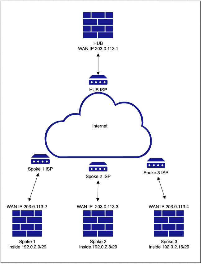
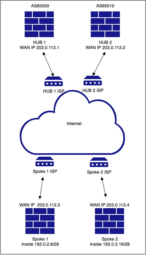
HUB & Spoke (Single ISP)
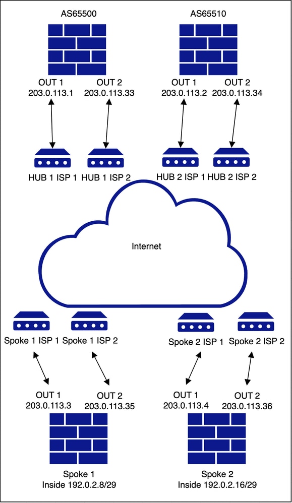
Network Diagram
Configurations
-
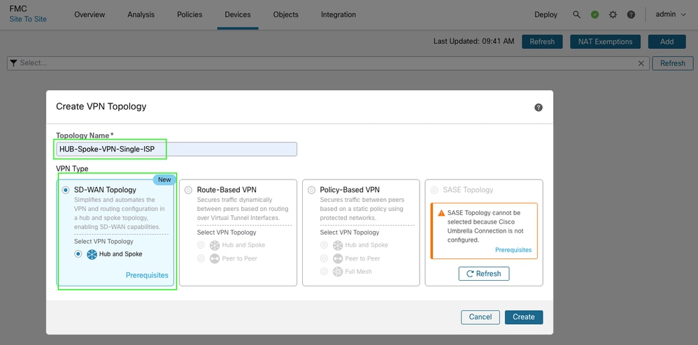
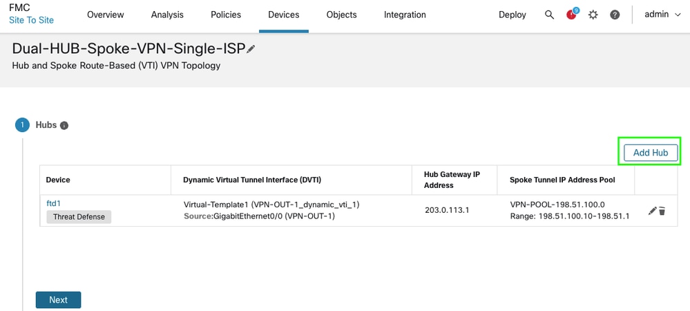
Navigate to Devices > VPN > Site to Site > Add > SD-WAN Topology > > Create.
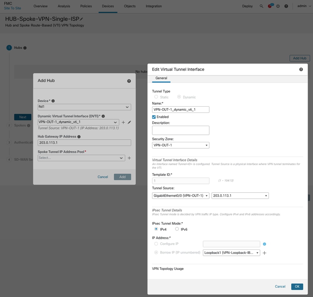
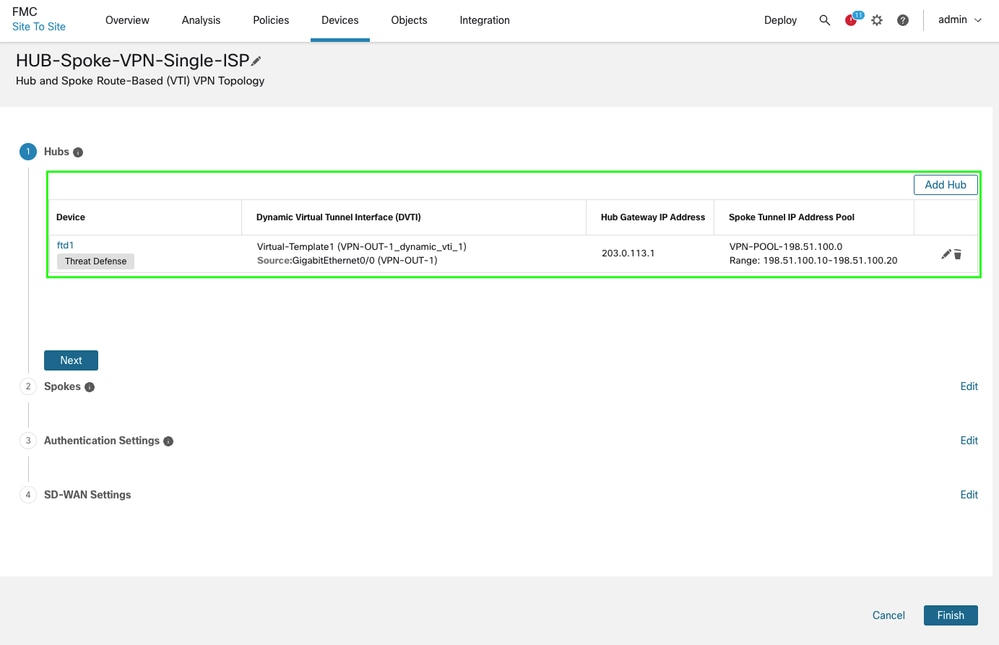
• Add a hub and create a DVTI at the hub end. As part of DVTI configuration, please ensure to select correct tunnel source interface as per the topology.
-
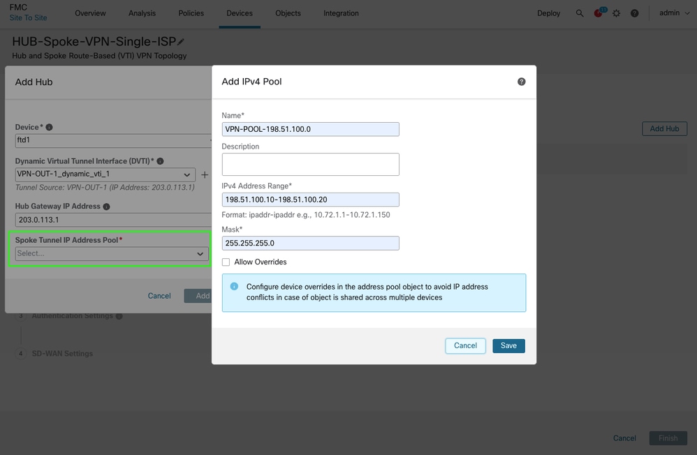
Create a Spoke Tunnel IP address pool and click Save and then Add. The ip address pool is used to assign VTI tunnel IP addresses to the spokes.
-
Click Next to proceed and add the spokes. You can leverage either bulk addition option if you have common interface / zone names or add spokes individually.
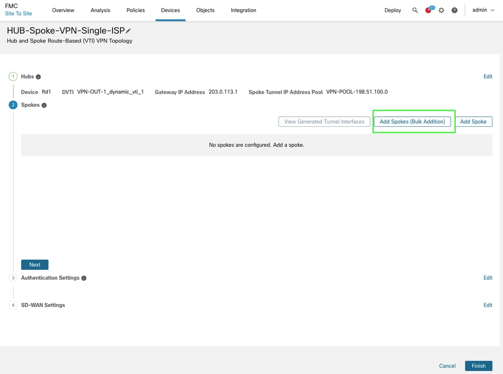
-
Select the devices and specify a naming pattern for the WAN/outside interface. If the devices share the same interface name, using initials is sufficient. Click Next, and if the validation is successful, click Add. For bulk additions, you can also use the zone name in the same way.
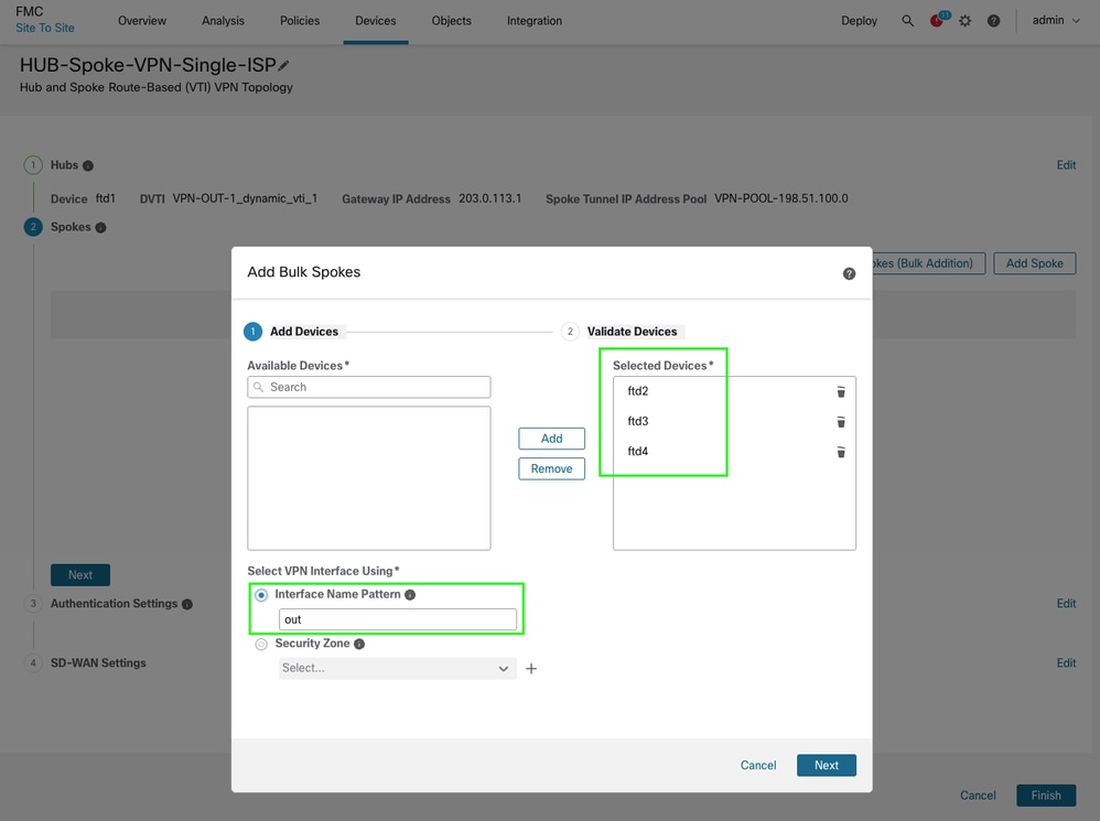
-
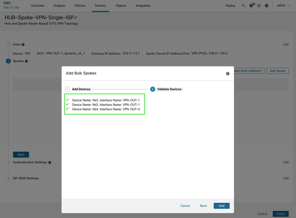
Verify the spokes and overlay interface details to ensure that the correct interfaces are selected, then click Next.
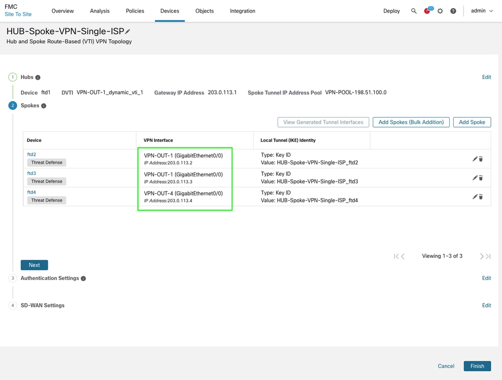
-
You can either retain the default parameters for the IPsec configuration or specify custom ciphers as required. Click Next to proceed. In this document, you are using the default parameters.
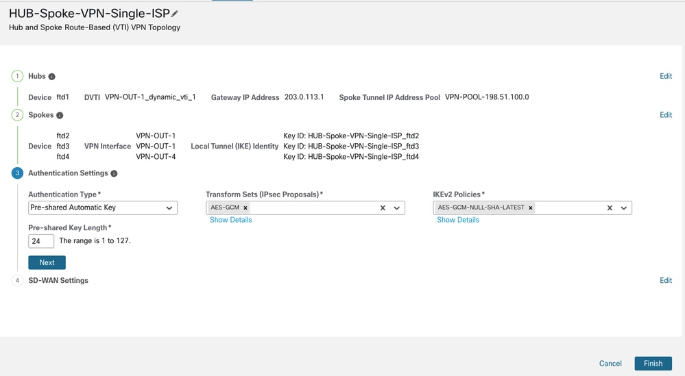
-
Finally, you can configure overlay routing within the same wizard for this topology by specifying the appropriate BGP parameters, such as the AS number, inside interface advertisement, and community tags for prefix filtering. Security zone can assist in traffic filtering via access control policies while you can also create an object for interfaces and use them in connected interfaces redistribution if the name is different than inside or is not symmetric across devices in the topology.
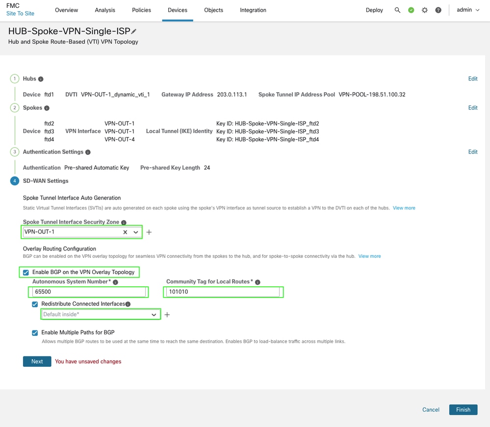
-
Click Next, then Finish, and finally Deploy to complete the process.
Verification
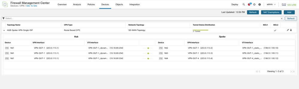
-
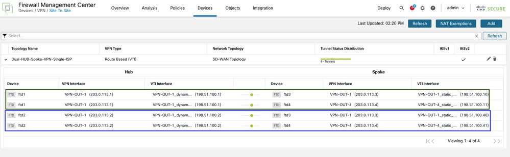
You can verify the tunnel status by navigating to Devices > VPN > Site to Site.
-
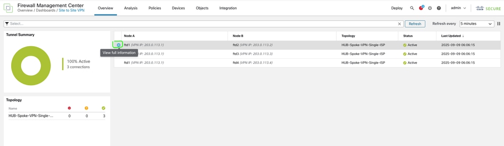
Additional details can be verified by navigating to Overview > Dashboards > Site to Site VPN.
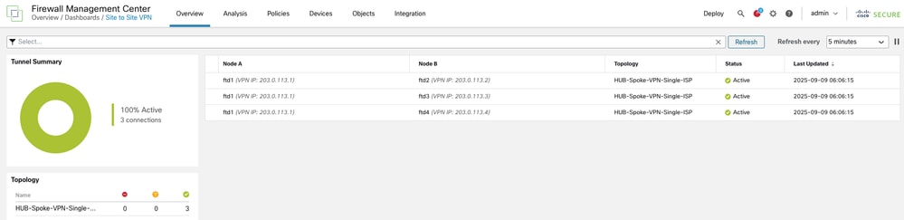
-
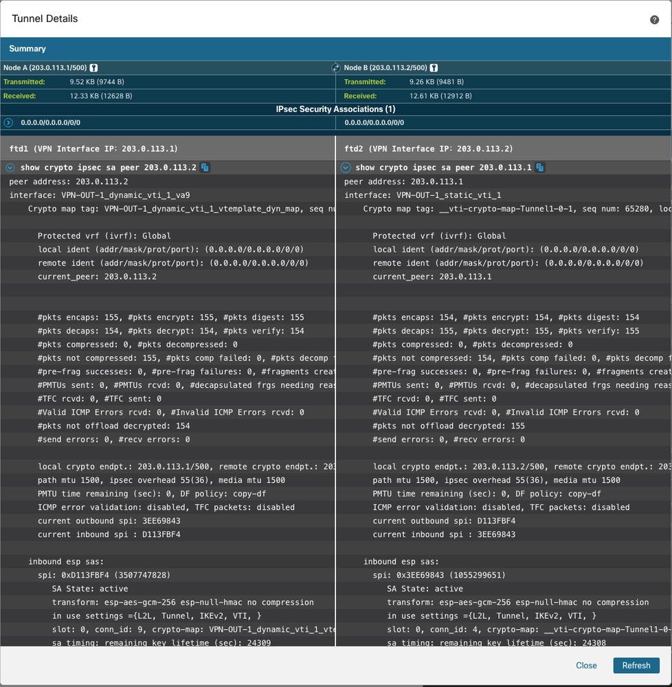
For further insights, select the tunnel and click View Full Information.
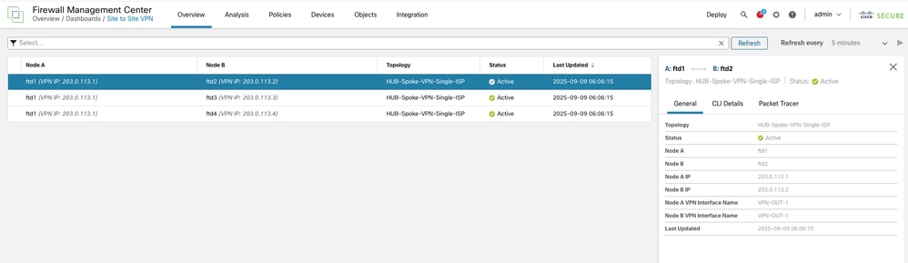
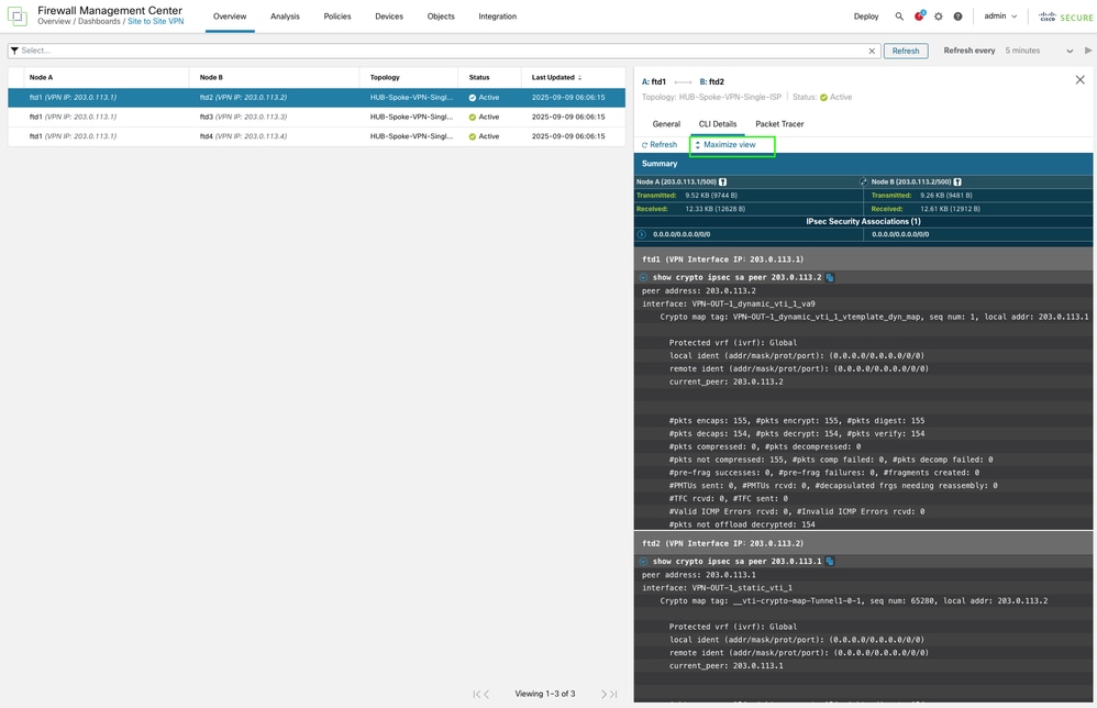
-
The output is shown directly from the FTD CLI and can be refreshed to display updated counters and important information, such as Security Parameter Index (SPI) details.
-
The FTD CLI can also be used to check routing information and BGP peering status.
On HUB side
HUB1# show bgp summary
BGP router identifier 198.51.100.3, local AS number 65500
BGP table version is 7, main routing table version 7
2 network entries using 400 bytes of memory
2 path entries using 160 bytes of memory
1/1 BGP path/bestpath attribute entries using 208 bytes of memory
1 BGP community entries using 24 bytes of memory
1 BGP route-map cache entries using 64 bytes of memory
0 BGP filter-list cache entries using 0 bytes of memory
BGP using 856 total bytes of memory
BGP activity 2/0 prefixes, 4/2 paths, scan interval 60 secs

Neighbor        V           AS MsgRcvd MsgSent   TblVer  InQ OutQ Up/Down  State/PfxRcd
198.51.100.10   4        65500 4       6              7    0    0 00:00:45  0 <<<<< spoke 1 bgp peering
198.51.100.11   4        65500 5       5              7    0    0 00:00:44  1 <<<<< spoke 2 bgp peering
198.51.100.12   4        65500 5       5              7    0    0 00:00:52  1 <<<<< spoke 3 bgp peering
HUB1# show route bgp
Codes: L - local, C - connected, S - static, R - RIP, M - mobile, B - BGP
       D - EIGRP, EX - EIGRP external, O - OSPF, IA - OSPF inter area
       N1 - OSPF NSSA external type 1, N2 - OSPF NSSA external type 2
       E1 - OSPF external type 1, E2 - OSPF external type 2, V - VPN
       i - IS-IS, su - IS-IS summary, L1 - IS-IS level-1, L2 - IS-IS level-2
       ia - IS-IS inter area, * - candidate default, U - per-user static route
       o - ODR, P - periodic downloaded static route, + - replicated route
       SI - Static InterVRF, BI - BGP InterVRF
Gateway of last resort is not set

B        192.0.2.0 255.255.255.248 [200/1] via 198.51.100.10, 00:00:18 <<<<<<<< spoke 1 inside network
B        192.0.2.8 255.255.255.248 [200/1] via 198.51.100.11, 00:08:08 <<<<<<<< spoke 2 inside network
B        192.0.2.16 255.255.255.248 [200/1] via 198.51.100.12, 00:08:16 <<<<<<<< spoke 3 inside network
HUB1#show bgp ipv4 unicast neighbors 198.51.100.10 routes <<<<< to check only prefix receieved from specific peer
BGP table version is 14, local router ID is 198.51.100.3
Status codes: s suppressed, d damped, h history, * valid, > best, i - internal,
r RIB-failure, S Stale, m multipath
Origin codes: i - IGP, e - EGP, ? - incomplete
Network Next Hop Metric LocPrf Weight Path
*>i192.0.2.0/29 198.51.100.10 1 100 0 ? <<<<<<<<<< routes received from spoke 1
Total number of prefixes 1HUB1#show bgp ipv4 unicast neighbors 198.51.100.11 routes <<<<< to check only prefix receieved from specific peer
BGP table version is 14, local router ID is 198.51.100.3 Status codes: s suppressed, d damped, h history, * valid, > best, i - internal, r RIB-failure, S Stale, m multipath Origin codes: i - IGP, e - EGP, ? - incomplete Network Next Hop Metric LocPrf Weight Path *>i192.0.2.8/29 198.51.100.11 1 100 0 ? <<<<<<<<<< routes received from spoke 2 Total number of prefixes 1
HUB1#show bgp ipv4 unicast neighbors 198.51.100.12 routes <<<<< to check only prefix receieved from specific peer

BGP table version is 14, local router ID is 198.51.100.3
Status codes: s suppressed, d damped, h history, * valid, > best, i - internal,
              r RIB-failure, S Stale, m multipath
Origin codes: i - IGP, e - EGP, ? - incomplete

   Network          Next Hop        Metric LocPrf Weight  Path
*>i192.0.2.16/29    198.51.100.12        1    100      0  ? <<<<<<<<<< routes received from spoke 3

Total number of prefixes 1
On Spoke Side
The same verification can be performed on the spoke devices as well. Here is an example from one of the spokes.
Spoke1# show bgp summary
BGP router identifier 198.51.100.4, local AS number 65500
BGP table version is 12, main routing table version 12
3 network entries using 600 bytes of memory
3 path entries using 240 bytes of memory
2/2 BGP path/bestpath attribute entries using 416 bytes of memory
2 BGP rrinfo entries using 80 bytes of memory
1 BGP community entries using 24 bytes of memory
0 BGP route-map cache entries using 0 bytes of memory
0 BGP filter-list cache entries using 0 bytes of memory
BGP using 1360 total bytes of memory
BGP activity 5/2 prefixes, 7/4 paths, scan interval 60 secs

Neighbor        V           AS MsgRcvd MsgSent   TblVer  InQ OutQ Up/Down  State/PfxRcd
198.51.100.1    4        65500 12      11            12    0    0 00:07:11  2    <<<<<<<<< BGP peering with HUB
Spoke1# show bgp ipv4 unicast neighbors 198.51.100.1 routes

BGP table version is 12, local router ID is 198.51.100.4
Status codes: s suppressed, d damped, h history, * valid, > best, i - internal,
              r RIB-failure, S Stale, m multipath
Origin codes: i - IGP, e - EGP, ? - incomplete

   Network          Next Hop        Metric LocPrf Weight  Path
*>i192.0.2.8/29     198.51.100.1         1    100      0  ? <<<<<<< route received from HUB for spoke 2
*>i192.0.2.16/29    198.51.100.1         1    100      0  ? <<<<<<< route received from HUB for spoke 3

Total number of prefixes 2
Spoke1# show bgp ipv4 unicast neighbors 198.51.100.1 advertised-routes
BGP table version is 12, local router ID is 198.51.100.4
Status codes: s suppressed, d damped, h history, * valid, > best, i - internal,
r RIB-failure, S Stale, m multipath
Origin codes: i - IGP, e - EGP, ? - incomplete
Network Next Hop Metric LocPrf Weight Path
*> 192.0.2.0/29 0.0.0.0 0 32768 ? <<<<<<<< route advertised by this spoke into BGP
Total number of prefixes 1 Spoke1# show route bgp
Codes: L - local, C - connected, S - static, R - RIP, M - mobile, B - BGP
D - EIGRP, EX - EIGRP external, O - OSPF, IA - OSPF inter area
N1 - OSPF NSSA external type 1, N2 - OSPF NSSA external type 2
E1 - OSPF external type 1, E2 - OSPF external type 2, V - VPN
i - IS-IS, su - IS-IS summary, L1 - IS-IS level-1, L2 - IS-IS level-2
ia - IS-IS inter area, * - candidate default, U - per-user static route
o - ODR, P - periodic downloaded static route, + - replicated route
SI - Static InterVRF, BI - BGP InterVRF
Gateway of last resort is not set
B 192.0.2.8 255.255.255.248 [200/1] via 198.51.100.1, 00:13:42 <<<<<< spoke 2 inside network
B 192.0.2.16 255.255.255.248 [200/1] via 198.51.100.1, 00:13:42 <<<<<< spoke 3 inside networkDual HUB & Spoke (SIngle ISP for Redundant HUB via EBGP Between Secondary HUB and Spokes)
Network Diagram
Configurations
The same wizard is required, with minor modifications in the HUB addition window. You can fast forward the process by focusing only on the necessary changes.
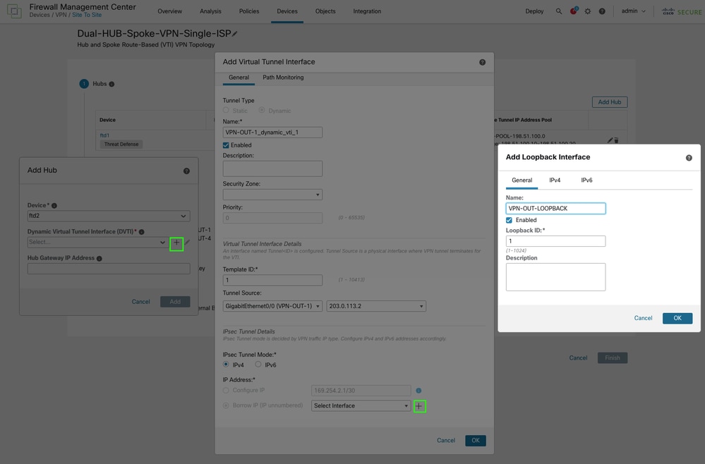
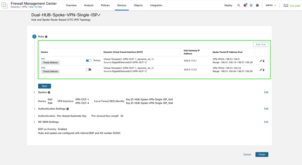
• After adding the first HUB, proceed to add the second HUB using the same steps previously used for HUB1.
-
Proceed to create the Dynamic Virtual Tunnel Interface (DVTI).
-
A new IP address pool is required for HUB 2 VTI tunnels on the spoke side. Create and configure the new pool, then save the changes.
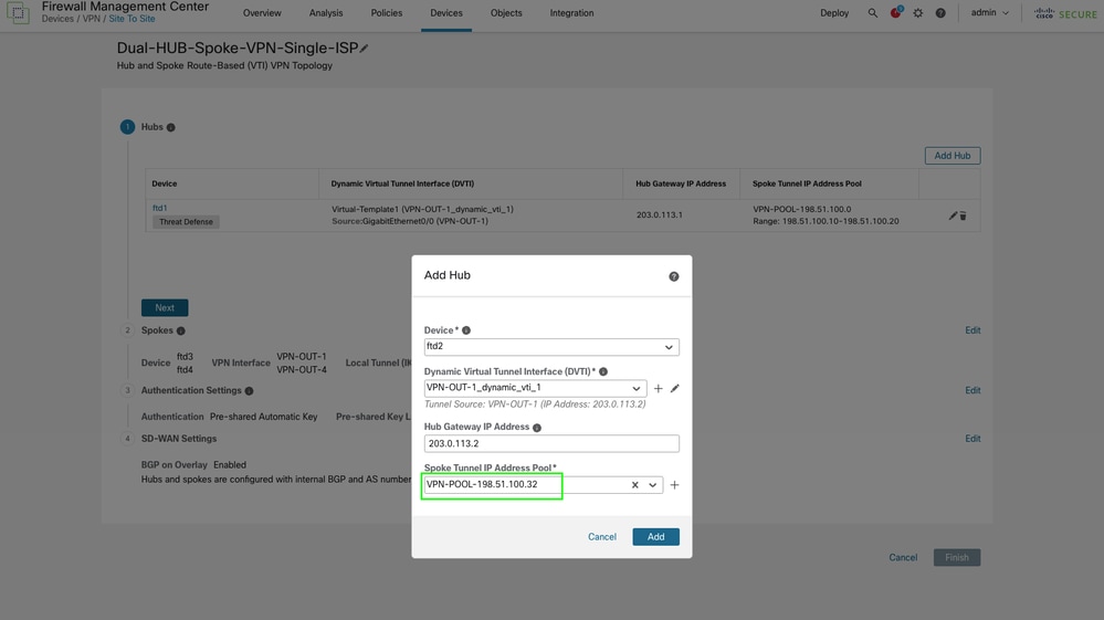
-
To configure eBGP peering between the second HUB and the spokes, modify the SD-WAN settings in the final step. Enable the option Secondary HUB is in a different Autonomous System and specify the Autonomous System (AS) number for the secondary HUB. IBGP can also be used if there is no limitation of using different AS number on your environment by leaving the option Secondary HUB is in a different Autonomous System unchecked. This pushes the same community tag and AS number for secondary HUB as well. The article focuses on eBGP for current setup.
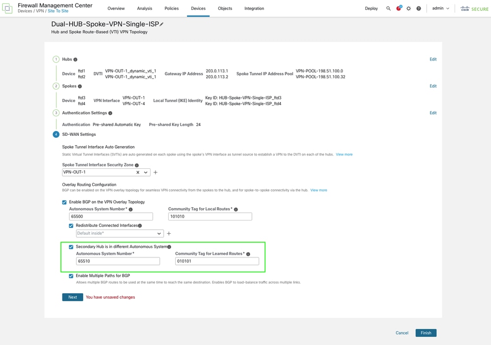
Ensure that both the Autonomous System (AS) number and the community tag are unique in this configuration.
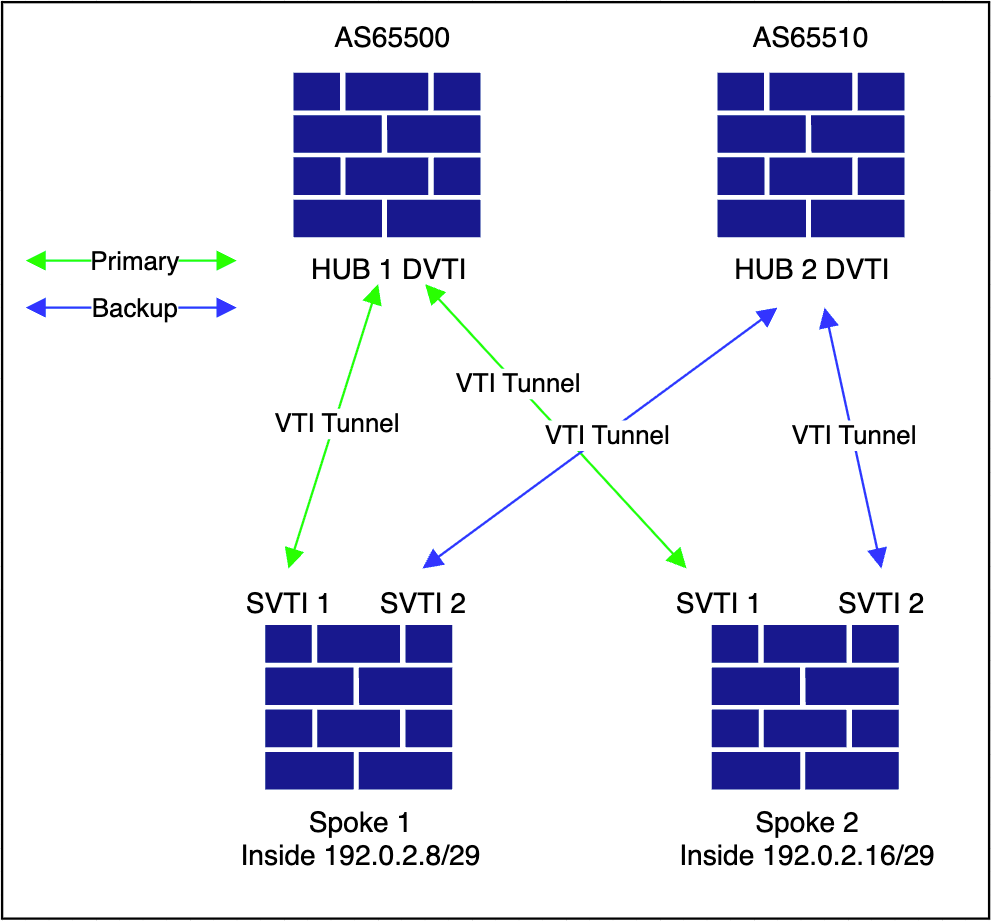
Verification
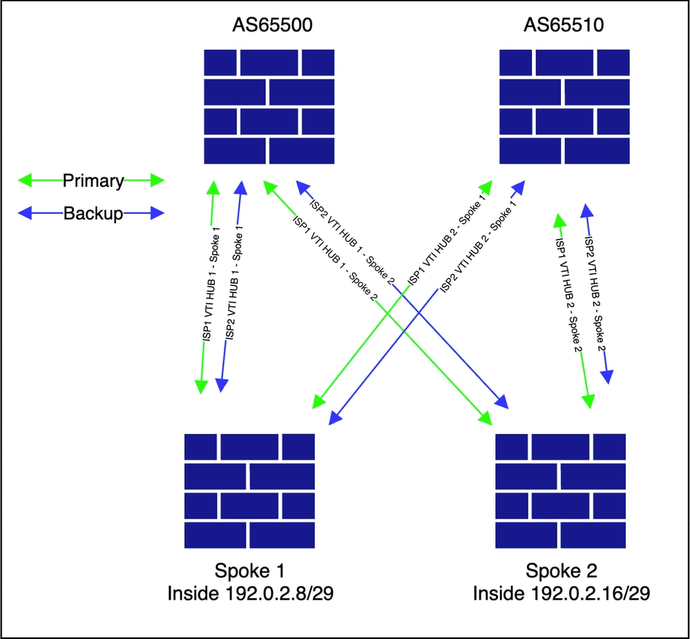
This diagram illustrates the overlay topology.
-
In the FMC, navigate to Devices > VPN > Site to Site.
-
All other steps remain unchanged.
Dual HUB & Spoke (Dual ISP for Redundant HUB and ISP via EBGP Between Secondary HUB and Spokes)
Network Diagram
Configuration
The only difference in this scenario is that two separate SD-WAN topologies are configured, each utilizing its respective ISP interface as the underlay.
• The deployment for this topology is skipped using the first ISP. since that is covered in previous topology.
-
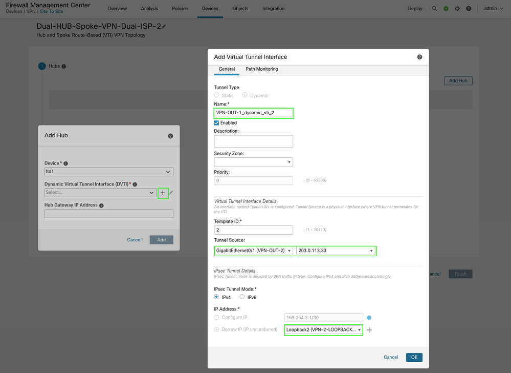
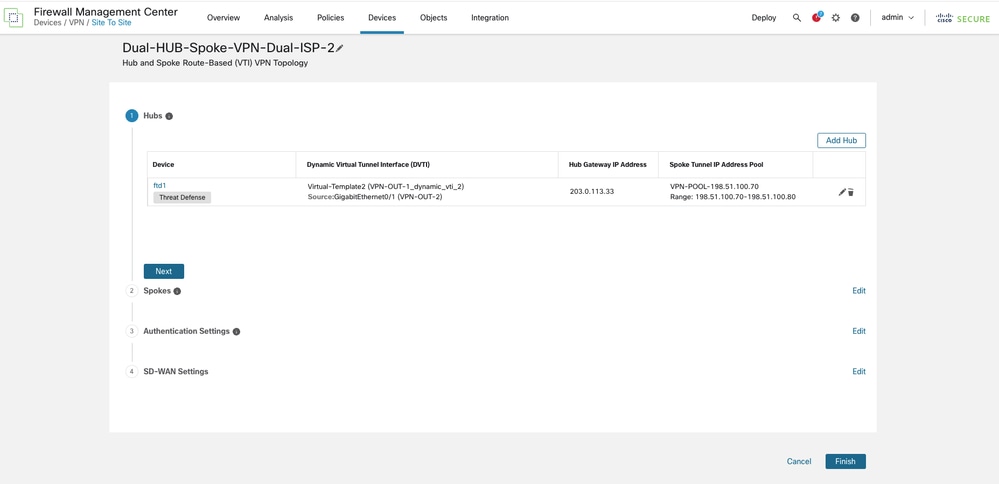
Next, proceed to add the second topology by creating two additional DVTI interfaces per HUB, each utilizing the underlay interface for ISP 2 (VPN-OUT-2).
-
An additional VPN IP address pool is provisioned specifically for spoke Virtual Tunnel Interface (VTI) addresses.
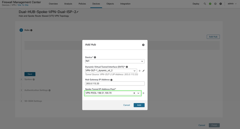
-
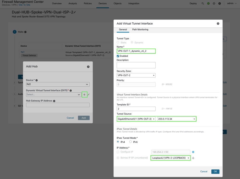
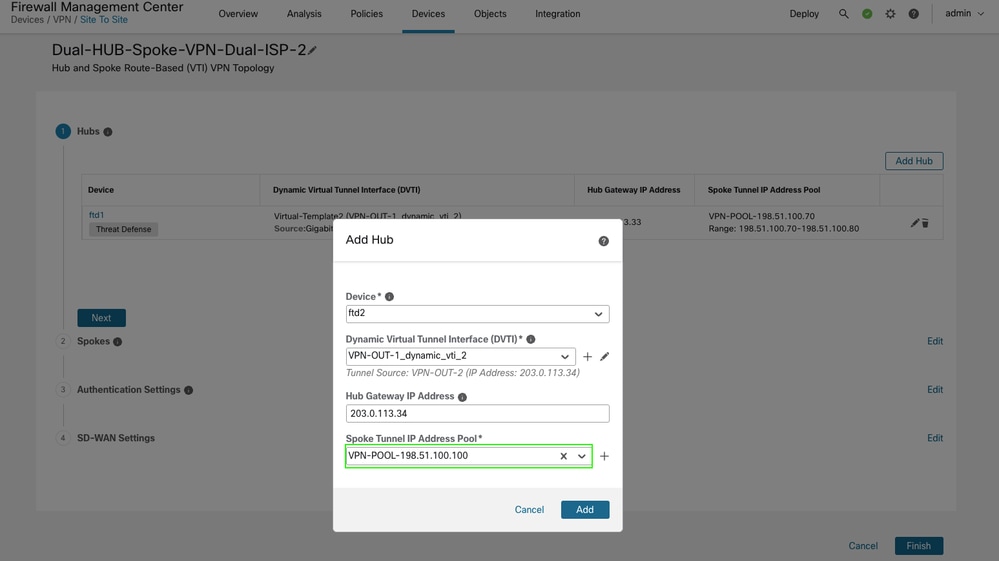
To add a secondary hub, repeat the process by creating DVTI 2 using the secondary ISP interface (VPN-OUT-2), and configure an additional IP pool for spoke-end VTI addresses.
-
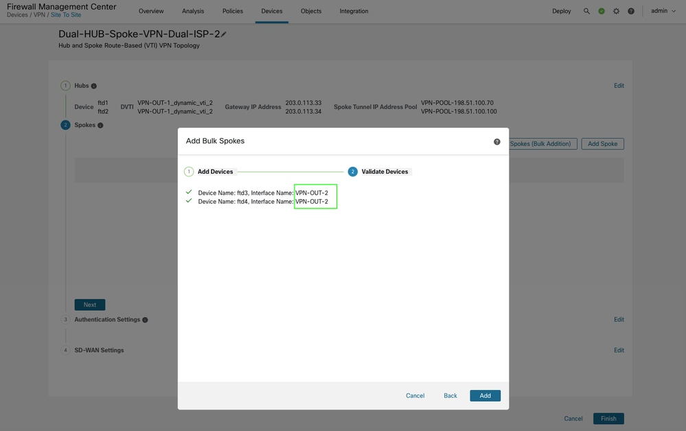
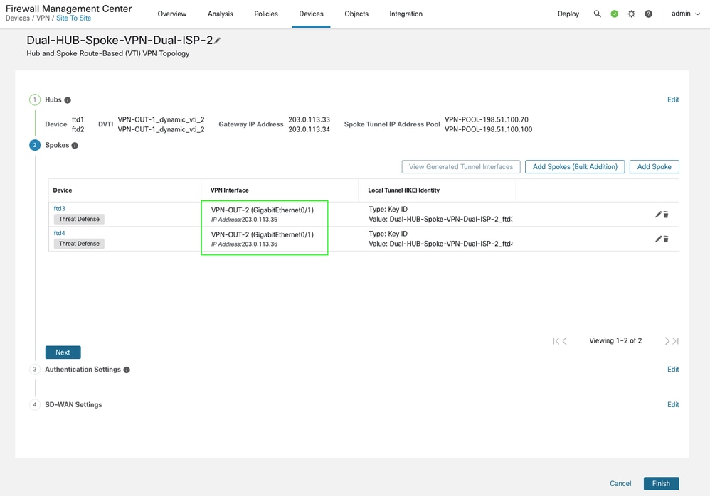
When adding a spoke, ensure that the correct underlay / WAN interface is specified for the VTI tunnels. This topology is using secondary ISP interface VPN-OUT-2.
-
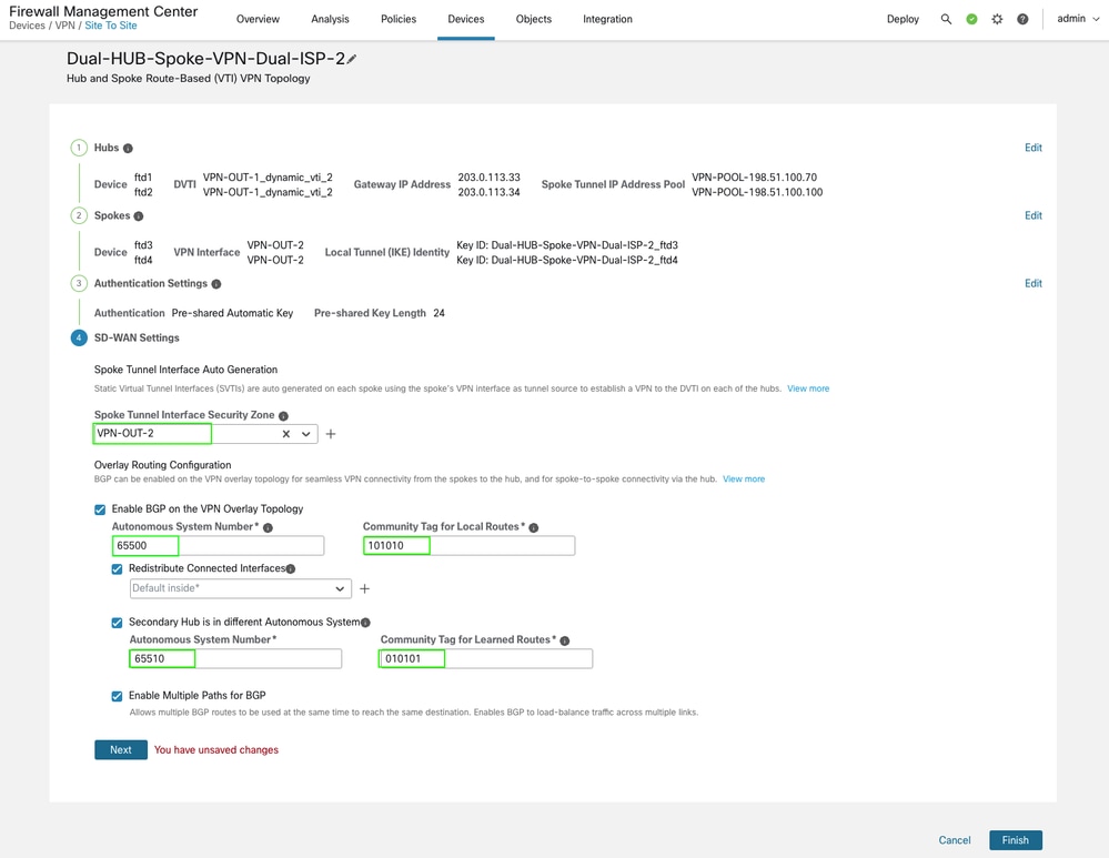
When configuring routing, ensure that the community tags and AS numbers for both HUBs in this topology are consistent with those used in the previous ISP1 topology. The topology is using different security zones but remaining configurations like AS numbers for primary and secondary HUBs along with community tags are the same. This is mandatory for the UI to complete the topology validation.
-
All other settings remain unchanged. Complete the wizard and proceed with deployment.
Verification
-
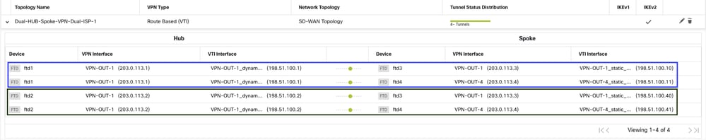
The topology appears as shown.
-
Navigate to Devices > VPN > Site to Site to view the topology.
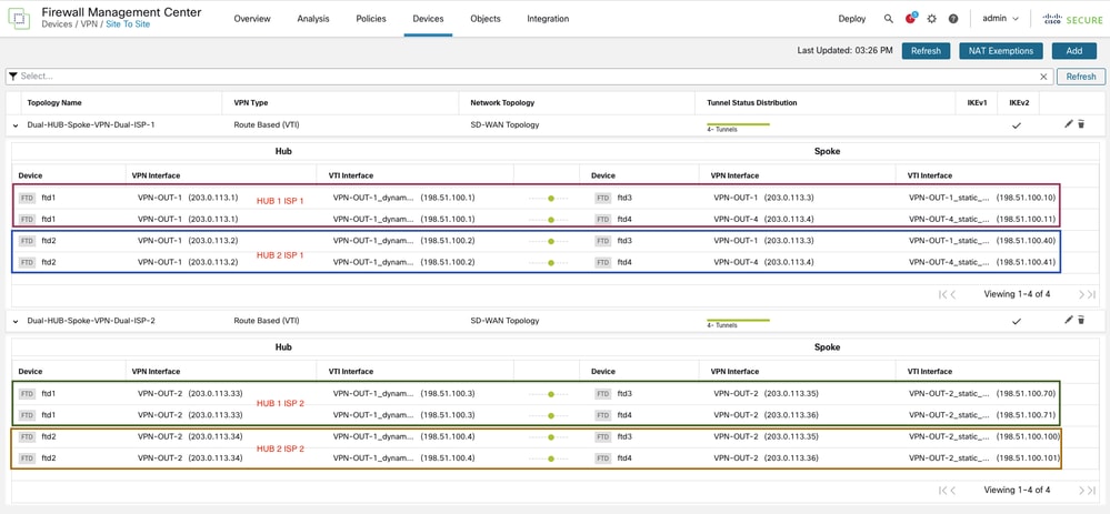
This configuration results in four BGP peerings per device, and each spoke has the appropriate routes to reach other spokes. As an example, you can retrieve the output from one of the spokes.
For Spoke 1
Spoke1#show bgp summary
BGP router identifier 203.0.113.35, local AS number 65500
BGP table version is 4, main routing table version 4
2 network entries using 400 bytes of memory
7 path entries using 560 bytes of memory
1 multipath network entries and 2 multipath paths
3/2 BGP path/bestpath attribute entries using 624 bytes of memory
1 BGP rrinfo entries using 40 bytes of memory
1 BGP AS-PATH entries using 40 bytes of memory
2 BGP community entries using 48 bytes of memory
0 BGP route-map cache entries using 0 bytes of memory
0 BGP filter-list cache entries using 0 bytes of memory
BGP using 1712 total bytes of memory
BGP activity 2/0 prefixes, 7/0 paths, scan interval 60 secs

Neighbor        V           AS MsgRcvd MsgSent   TblVer  InQ OutQ Up/Down  State/PfxRcd
198.51.100.1    4        65500 229     226            4    0    0 04:07:22  1 <<<<<<<<<< HUB 1 ISP 1 VTI
198.51.100.2    4        65510 226     230            4    0    0 04:06:36  2 <<<<<<<<<< HUB 2 ISP 1 VTI
198.51.100.3    4        65500 182     183            4    0    0 03:16:45  1 <<<<<<<<<< HUB 1 ISP 2 VTI
198.51.100.4    4        65510 183     183            4    0    0 03:16:30  2 <<<<<<<<<< HUB 2 ISP 2 VTI
Spoke1#show bgp ipv4 unicast neighbors 198.51.100.1 routes <<<< check for specific prefixes received via HUB1 ISP1

BGP table version is 4, local router ID is 203.0.113.35
Status codes: s suppressed, d damped, h history, * valid, > best, i - internal,
              r RIB-failure, S Stale, m multipath
Origin codes: i - IGP, e - EGP, ? - incomplete

   Network          Next Hop        Metric LocPrf Weight  Path
*>i192.0.2.16/29    198.51.100.1         1    100      0  ? <<<<<<<< spoke 2 network received via HUB 1 ISP 1 tunnel

Total number of prefixes 1
Spoke1#show bgp ipv4 unicast neighbors 198.51.100.3 routes <<<< check for specific prefixes received via HUB1 ISP2
BGP table version is 4, local router ID is 203.0.113.35
Status codes: s suppressed, d damped, h history, * valid, > best, i - internal,
r RIB-failure, S Stale, m multipath
Origin codes: i - IGP, e - EGP, ? - incomplete
Network Next Hop Metric LocPrf Weight Path
*mi192.0.2.16/29 198.51.100.3 1 100 0 ? <<<<<<<< spoke 2 network received via HUB 1 ISP 2 tunnel
Total number of prefixes 1 Spoke1# show bgp ipv4 unicast neighbors 198.51.100.2 routes <<<< check for specific prefixes received via HUB2 ISP1
BGP table version is 4, local router ID is 203.0.113.35 Status codes: s suppressed, d damped, h history, * valid, > best, i - internal, r RIB-failure, S Stale, m multipath Origin codes: i - IGP, e - EGP, ? - incomplete Network Next Hop Metric LocPrf Weight Path * 192.0.2.8/29 198.51.100.2 100 0 65510 65510 ? <<<<<<< inside network receieved cause we advertised it to HUB 1 from ISP 2 topology * 192.0.2.16/29 198.51.100.2 100 0 65510 65510 ? <<<<<<<< spoke 2 network received via HUB 2 ISP 1 tunnel but not preferred Total number of prefixes 2
Spoke1# show bgp ipv4 unicast neighbors 198.51.100.4 routes <<<< check for specific prefixes received via HUB2 ISP1
BGP table version is 4, local router ID is 203.0.113.35
Status codes: s suppressed, d damped, h history, * valid, > best, i - internal,
              r RIB-failure, S Stale, m multipath
Origin codes: i - IGP, e - EGP, ? - incomplete

   Network          Next Hop        Metric LocPrf Weight  Path
*  192.0.2.8/29     198.51.100.4       100             0  65510 65510 ? <<<<<<< inside network receieved cause we advertised it to HUB 2 from ISP 1 topology
*  192.0.2.16/29    198.51.100.4       100             0  65510 65510 ? <<<<<<<< spoke 2 network received via HUB 2 ISP 2 tunnel but not preferred

Total number of prefixes 2
The routing table appears as shown which confirms traffic is load-balanced between both links at spoke side.
Spoke1#show route bgp

Codes: L - local, C - connected, S - static, R - RIP, M - mobile, B - BGP
       D - EIGRP, EX - EIGRP external, O - OSPF, IA - OSPF inter area
       N1 - OSPF NSSA external type 1, N2 - OSPF NSSA external type 2
       E1 - OSPF external type 1, E2 - OSPF external type 2, V - VPN
       i - IS-IS, su - IS-IS summary, L1 - IS-IS level-1, L2 - IS-IS level-2
       ia - IS-IS inter area, * - candidate default, U - per-user static route
       o - ODR, P - periodic downloaded static route, + - replicated route
       SI - Static InterVRF, BI - BGP InterVRF
Gateway of last resort is not set

B        192.0.2.16 255.255.255.248 [200/1] via 198.51.100.3, 03:23:53 <<<<< multipath for spoke 2 inside network
                                    [200/1] via 198.51.100.1, 03:23:53 <<<<< multipath for spoke 2 inside network
Spoke1#show bgp 192.0.2.16
BGP routing table entry for 192.0.2.16/29, version 4
Paths: (4 available, best #4, table default)
Multipath: eBGP iBGP
Advertised to update-groups:
2 4
65510 65510
198.51.100.4 from 198.51.100.4 (198.51.100.4) <<<< HUB2 ISP2 next-hop
Origin incomplete, metric 100, localpref 100, valid, external
Community: 10101
Local
198.51.100.3 from 198.51.100.3 (198.51.100.3) <<<< HUB1 ISP2 next-hop
Origin incomplete, metric 1, localpref 100, valid, internal, multipath
Community: 10101
Originator: 203.0.113.36, Cluster list: 198.51.100.3
65510 65510
198.51.100.2 from 198.51.100.2 (198.51.100.4) <<<< HUB2 ISP1 next-hop
Origin incomplete, metric 100, localpref 100, valid, external
Community: 10101
Local
198.51.100.1 from 198.51.100.1 (198.51.100.3) <<<< HUB1 ISP1 next-hop
Origin incomplete, metric 1, localpref 100, valid, internal, multipath, best
Community: 10101
Originator: 203.0.113.36, Cluster list: 198.51.100.3Conclusion
The purpose of this article is to explain various deployment scenarios that can be easily implemented using a single setup wizard.
Related Information
- For additional assistance, please contact TAC. A valid support contract is required:Cisco Worldwide Support Contacts.
- You can also visit the Cisco VPN Community here.
Revision History
| Revision | Publish Date | Comments |
|---|---|---|
1.0 |
01-Oct-2025
|
Initial Release |
Contributed by Cisco Engineers
- Daniyal AkhtarTechnical Consulting Engineer
 Feedback
Contact Cisco
- Open a Support Case

- (Requires a Cisco Service Contract)