PDF(669.3 KB) View with Adobe Reader on a variety of devices
ePub(697.5 KB) View in various apps on iPhone, iPad, Android, Sony Reader, or Windows Phone
Mobi (Kindle)(439.5 KB) View on Kindle device or Kindle app on multiple devices
Updated:July 2, 2026
Document ID:226098
Bias-Free Language
The documentation set for this product strives to use bias-free language. For the purposes of this documentation set, bias-free is defined as language that does not imply discrimination based on age, disability, gender, racial identity, ethnic identity, sexual orientation, socioeconomic status, and intersectionality. Exceptions may be present in the documentation due to language that is hardcoded in the user interfaces of the product software, language used based on RFP documentation, or language that is used by a referenced third-party product. Learn more about how Cisco is using Inclusive Language.
This document describes the process to configure route leaking with the use of Route Replication feature in Cisco IOS XE.
Prerequisites
Requirements
Cisco recommends that you have knowledge of these topics:
Knowledge of Basic IP Routing
Knowledge of Cisco IOS XE Command Line Interface (CLI)
Components Used
The information in this document is based on these software and hardware versions:
Cisco Catalyst 8500 Series Edge Platforms
Cisco Catalyst 9500 Series Switches
Cisco IOS XE version 17.15.X and 17.12.X
The information in this document was created from the devices in a specific lab environment. All of the devices used in this document started with a cleared (default) configuration. If your network is live, ensure that you understand the potential impact of any command.
Background Information
Network segmentation is the practice of dividing a network into smaller, isolated portions to improve security, manageability, and operational efficiency. Segmentation can be implemented at different layers of the network, for example VLANs provide Layer 2 separation, while Virtual Routing and Forwarding (VRF) delivers Layer 3 isolation by allowing a single physical device to maintain multiple independent routing tables simultaneously. Each VRF operates as a self-contained routing instance with its own set of interfaces, routing protocols, and forwarding decisions, ensuring that traffic from one segment does not intermix with traffic from another.
Organizations adopt segmentation for a variety of reasons, including separating lines of business, isolating guest users from corporate resources, meeting regulatory compliance requirements, providing controlled access to business partners, or reducing the scope of potential security incidents. By default, VRFs do not share routing information, which preserves the boundaries between segments and ensures that prefixes contained within one VRF remain unreachable from another.
While VRF based segmentation provides strong traffic isolation, real world deployments often require selective connectivity between these segments. Particularly, for example, when multiple VRFs need access to common resources such as DNS, DHCP, application servers, or other shared services. Route Replication addresses this requirement by copying routes from one VRF into another, enabling controlled inter-VRF reachability without dismantling the underlying segmentation model.
Route Replication is supported for static, EIGRP, and OSPF routes, and is configured directly under the VRF address-family using the route-replicate command. Optional route maps can be applied to filter which prefixes are replicated, providing granular control and helping prevent routing loops. Replicated routes inherit the administrative distance and source protocol of the original route, and are propagated across virtual networks through standard Interior Gateway Protocol (IGP) redistribution.
There are different techniques to perform route leaking between VRFs and/or the Global Routing Table (GRT), the main difference of using the Route Replication feature is that an additional BGP process is no longer needed to achieve the leaking, and in some scenarios Route Replication can be seen as an easier method as only a few commands are needed.
Note: Although Route Replication is sometimes less commonly used in deployments, it is not a new feature. The route-replicate command was introduced in Cisco IOS XE Release 3.2S and remains a valid option for enabling controlled route leaking between VRFs and the GRT.
Note: Please also note that Route Replication and Redistribution of BGP routes was introduced in Cisco IOS XE Release 17.6.1, please refer to IP Routing Configuration Guide, Cisco IOS XE 17.x for more information.
Network Scenarios
Scenario 1 - VRF to VRF Route Leaking
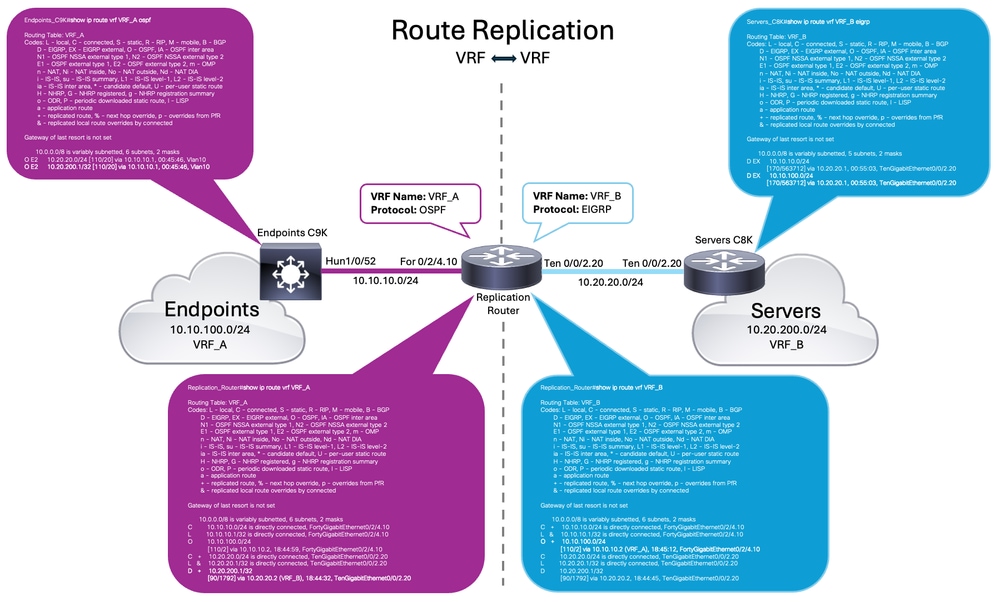
This scenario demonstrates how the Route Replication feature enables selective connectivity between two isolated routing domains through a single device.
The network is divided into two segments, separated by the central Catalyst 8500 Series Router (Replication Router):
VRF_A (left side - OSPF): A Catalyst 9500 Series Switch connects the Endpoints segment (10.10.100.0/24). The link between the C9K and the Replication Router uses subnet 10.10.10.0/24, where the interface is FortyGigabitEthernet0/2/4.10 (10.10.10.1).
VRF_B (right side - EIGRP): A Catalyst 8500 Series Router connects the Servers segment (10.20.200.0/24). The link between this C8K and the Replication Router uses subnet 10.20.20.0/24, where the Replication Router interface is TenGigabitEthernet0/0/2.20 (10.20.20.1).
Network Diagram
Route Replicatio Topology - Scenario1 (VRF to VRF)
Configurations
Step 1. Define VRF Instances
Start by defining your VRFs. This step creates the independent routing tables that keep your network segments isolated. By creating VRF_A and VRF_B, you establish the foundation for your separate environments. You can think of this as creating two distinct "lanes" for your data to travel through.
Replication Router
Replication_Router#configure terminal
Enter configuration commands, one per line.  End with CNTL/Z.
Replication_Router(config)#vrf definition VRF_A
Replication_Router(config-vrf)#description Tenant A - OSPF
Replication_Router(config-vrf)#address-family ipv4
Replication_Router(config-vrf-af)#exit-address-family
Replication_Router(config-vrf)#exit

Replication_Router(config)#vrf definition VRF_B
Replication_Router(config-vrf)#description Tenant B - EIGRP
Replication_Router(config-vrf)#address-family ipv4
Replication_Router(config-vrf-af)#exit-address-family
Replication_Router(config-vrf)#exit
Step 2. Assign interfaces to VRF Instances
Next, assign your interfaces to their respective VRFs. This step is important because it tells the router which physical or logical ports belong to which routing table. Without this mapping, the router cannot direct traffic into the correct segment. It ensures that data enters the specific lane you created in the first step.
Step 3. Configure Routing Protocols and Redistribution
In this scenario, OSPF and EIGRP protocols are being used to share routing information between the C9K connecting the endpoints and the C8K that provides reachability to the servers. This step allows the router to form OSPF and EIGRP neighbor relationships and dynamically learn and advertise routes.
Configuring redistribution prepares the router to share routing information between the different domains. This step is essential because it provides the visibility required to advertise the replicated routes. For example, a prefix learned from an OSPF neighbor in VRF_A can be replicated into VRF_B. Once the route exists in the VRF_B routing table, redistribution allows the router to advertise that prefix into the EIGRP process.
Finally, apply the route-replicate command within the address family of each VRF. This is the core of the feature. It allows you to import routes from one VRF into another directly. This method simplifies your configuration because it removes the need for an additional BGP process. It is a clean and effective way to achieve controlled reachability between your segments.
Replication Router (Pull OSPF routes from VRF_A into VRF_B)
Replication_Router(config)#vrf definition VRF_B
Replication_Router(config-vrf)#address-family ipv4
Replication_Router(config-vrf-af)#route-replicate from vrf VRF_A unicast connected
Replication_Router(config-vrf-af)#route-replicate from vrf VRF_A unicast ospf 100
Replication_Router(config-vrf-af)#exit-address-family
Replication Router (Pull EIGRP routes from VRF_B into VRF_A)
Replication_Router(config)#vrf definition VRF_A
Replication_Router(config-vrf)#address-family ipv4
Replication_Router(config-vrf-af)#route-replicate from vrf VRF_B unicast connected
Replication_Router(config-vrf-af)#route-replicate from vrf VRF_B unicast eigrp 200
Replication_Router(config-vrf-af)#exit-address-family
Verify
The outputs from the Route Replication router and neighbors confirm the leaking is successful:
In VRF_A, the EIGRP route 10.20.200.1/32 appears as a replicated route, marked with the + flag, learned via 10.20.20.2 (VRF_B).
In VRF_B, the OSPF route 10.10.100.0/24 appears as a replicated route, marked with the + flag, learned via 10.10.10.2 (VRF_A).
The Endpoints_C9K and Servers_C8K tables show the redistributed external routes (O E2 and D EX) reaching across to the opposite segment.
The ICMP tests confirm the end-to-end connectivity.
Routing Table important Flags/Codes
Code
Meaning
+
Replicated route — copied from the other VRF by route-replicate
&
Replicated local route, overridden by a connected route in the same VRF
(VRF_A) / (VRF_B)
Source VRF of a replicated route
Note: Routes without + flag are native to that VRF (directly connected or learned normally by OSPF/EIGRP inside the same VRF).
Replication Router
Replication_Router#show ip route vrf VRF_A
Routing Table: VRF_A
Codes: L - local, C - connected, S - static, R - RIP, M - mobile, B - BGP
       D - EIGRP, EX - EIGRP external, O - OSPF, IA - OSPF inter area
       N1 - OSPF NSSA external type 1, N2 - OSPF NSSA external type 2
       E1 - OSPF external type 1, E2 - OSPF external type 2, m - OMP
       n - NAT, Ni - NAT inside, No - NAT outside, Nd - NAT DIA
       i - IS-IS, su - IS-IS summary, L1 - IS-IS level-1, L2 - IS-IS level-2
       ia - IS-IS inter area, * - candidate default, U - per-user static route
       H - NHRP, G - NHRP registered, g - NHRP registration summary
       o - ODR, P - periodic downloaded static route, l - LISP
       a - application route
       + - replicated route, % - next hop override, p - overrides from PfR
       & - replicated local route overrides by connected
Gateway of last resort is not set
      10.0.0.0/8 is variably subnetted, 6 subnets, 2 masks
C        10.10.10.0/24 is directly connected, FortyGigabitEthernet0/2/4.10
L        10.10.10.1/32 is directly connected, FortyGigabitEthernet0/2/4.10
O        10.10.100.0/24
           [110/2] via 10.10.10.2, 00:03:37, FortyGigabitEthernet0/2/4.10
C   +    10.20.20.0/24 is directly connected, TenGigabitEthernet0/0/2.20
L   &    10.20.20.1/32 is directly connected, TenGigabitEthernet0/0/2.20
D + 10.20.200.1/32 [90/1792] via 10.20.20.2 (VRF_B), 3d00h, TenGigabitEthernet0/0/2.20

Replication_Router#show ip ospf neighbor

Neighbor ID     Pri   State           Dead Time   Address         Interface
10.10.100.2       1   FULL/BDR        00:00:34    10.10.10.2      FortyGigabitEthernet0/2/4.10

Replication_Router#show ip route vrf VRF_B
Routing Table: VRF_B
Codes: L - local, C - connected, S - static, R - RIP, M - mobile, B - BGP
       D - EIGRP, EX - EIGRP external, O - OSPF, IA - OSPF inter area
       N1 - OSPF NSSA external type 1, N2 - OSPF NSSA external type 2
       E1 - OSPF external type 1, E2 - OSPF external type 2, m - OMP
       n - NAT, Ni - NAT inside, No - NAT outside, Nd - NAT DIA
       i - IS-IS, su - IS-IS summary, L1 - IS-IS level-1, L2 - IS-IS level-2
       ia - IS-IS inter area, * - candidate default, U - per-user static route
       H - NHRP, G - NHRP registered, g - NHRP registration summary
       o - ODR, P - periodic downloaded static route, l - LISP
       a - application route
       + - replicated route, % - next hop override, p - overrides from PfR
       & - replicated local route overrides by connected
Gateway of last resort is not set
      10.0.0.0/8 is variably subnetted, 6 subnets, 2 masks
C   +    10.10.10.0/24 is directly connected, FortyGigabitEthernet0/2/4.10
L   &    10.10.10.1/32 is directly connected, FortyGigabitEthernet0/2/4.10
O + 10.10.100.0/24 [110/2] via 10.10.10.2 (VRF_A), 00:02:43, FortyGigabitEthernet0/2/4.10
C        10.20.20.0/24 is directly connected, TenGigabitEthernet0/0/2.20
L        10.20.20.1/32 is directly connected, TenGigabitEthernet0/0/2.20
D        10.20.200.1/32
           [90/1792] via 10.20.20.2, 3d00h, TenGigabitEthernet0/0/2.20

Replication_Router#show ip eigrp vrf VRF_B neighbors
EIGRP-IPv4 VR(MULTI_AF) Address-Family Neighbors for AS(200)
           VRF(VRF_B)
H   Address                 Interface              Hold Uptime   SRTT   RTO  Q  Seq
                                                   (sec)         (ms)       Cnt Num
0   10.20.20.2              Te0/0/2.20               14 3d01h       1   100  0  4
Replication_Router#
Endpoints Catalyst 9K
Servers Catalyst 8K
Endpoints_C9K#show ip route vrf VRF_A

Routing Table: VRF_A
Codes: L - local, C - connected, S - static, R - RIP, M - mobile, B - BGP
       D - EIGRP, EX - EIGRP external, O - OSPF, IA - OSPF inter area
       N1 - OSPF NSSA external type 1, N2 - OSPF NSSA external type 2
       E1 - OSPF external type 1, E2 - OSPF external type 2, m - OMP
       n - NAT, Ni - NAT inside, No - NAT outside, Nd - NAT DIA
       i - IS-IS, su - IS-IS summary, L1 - IS-IS level-1, L2 - IS-IS level-2
       ia - IS-IS inter area, * - candidate default, U - per-user static route
       H - NHRP, G - NHRP registered, g - NHRP registration summary
       o - ODR, P - periodic downloaded static route, l - LISP
       a - application route
       + - replicated route, % - next hop override, p - overrides from PfR
       & - replicated local route overrides by connected

Gateway of last resort is not set

      10.0.0.0/8 is variably subnetted, 6 subnets, 2 masks
C        10.10.10.0/24 is directly connected, Vlan10
L        10.10.10.2/32 is directly connected, Vlan10
C        10.10.100.0/24 is directly connected, Vlan100
L        10.10.100.2/32 is directly connected, Vlan100
O E2     10.20.20.0/24 [110/20] via 10.10.10.1, 00:47:21, Vlan10
O E2 10.20.200.1/32 [110/20] via 10.10.10.1, 00:47:21, Vlan10

Endpoints_C9K#show ip ospf neighbor

Neighbor ID     Pri   State           Dead Time   Address         Interface
10.10.10.1        1   FULL/DR         00:00:36    10.10.10.1      Vlan10

Endpoints_C9K#ping vrf VRF_A 10.20.200.1 source 10.10.100.2
Type escape sequence to abort.
Sending 5, 100-byte ICMP Echos to 10.20.200.1, timeout is 2 seconds:
Packet sent with a source address of 10.10.100.2
!!!!!
Success rate is 100 percent (5/5), round-trip min/avg/max = 1/1/1 ms
Endpoints_C9K#
Servers_C8K#show ip route vrf VRF_B

Routing Table: VRF_B
Codes: L - local, C - connected, S - static, R - RIP, M - mobile, B - BGP
       D - EIGRP, EX - EIGRP external, O - OSPF, IA - OSPF inter area
       N1 - OSPF NSSA external type 1, N2 - OSPF NSSA external type 2
       E1 - OSPF external type 1, E2 - OSPF external type 2, m - OMP
       n - NAT, Ni - NAT inside, No - NAT outside, Nd - NAT DIA
       i - IS-IS, su - IS-IS summary, L1 - IS-IS level-1, L2 - IS-IS level-2
       ia - IS-IS inter area, * - candidate default, U - per-user static route
       H - NHRP, G - NHRP registered, g - NHRP registration summary
       o - ODR, P - periodic downloaded static route, l - LISP
       a - application route
       + - replicated route, % - next hop override, p - overrides from PfR
       & - replicated local route overrides by connected

Gateway of last resort is not set

      10.0.0.0/8 is variably subnetted, 5 subnets, 2 masks
D EX     10.10.10.0/24
           [170/563712] via 10.20.20.1, 3d01h, TenGigabitEthernet0/0/2.20
D EX 10.10.100.0/24 [170/563712] via 10.20.20.1, 00:41:30, TenGigabitEthernet0/0/2.20
C        10.20.20.0/24 is directly connected, TenGigabitEthernet0/0/2.20
L        10.20.20.2/32 is directly connected, TenGigabitEthernet0/0/2.20
C        10.20.200.1/32 is directly connected, Loopback20

Servers_C8K#show ip eigrp vrf VRF_B neighbors
EIGRP-IPv4 VR(MULTI_AF) Address-Family Neighbors for AS(200)
           VRF(VRF_B)
H   Address                 Interface              Hold Uptime   SRTT   RTO  Q  Seq
                                                   (sec)         (ms)       Cnt Num
0   10.20.20.1              Te0/0/2.20               14 3d01h    1278  5000  0  4

Servers_C8K#ping vrf VRF_B 10.10.100.2 source 10.20.200.1
Type escape sequence to abort.
Sending 5, 100-byte ICMP Echos to 10.10.100.2, timeout is 2 seconds:
Packet sent with a source address of 10.20.200.1
!!!!!
Success rate is 100 percent (5/5), round-trip min/avg/max = 1/1/1 ms
Servers_C8K#
Scenario 2 - GRT to VRF Route Leaking
In this scenario, the Replication Router learns the Endpoints network 192.168.100.0/24 through OSPF in the GRT and replicates that route into VRF_B. After replication, the route appears in the VRF_B routing table as an OSPF learned replicated route and is then made available to the EIGRP domain on the Servers side after proper redistribution. In a similar way, Replication Router learns the Servers network 10.20.200.0/24 through EIGRP in the VRF_B and then replicates that route into GRT:
GRT (left side - OSPF): A Catalyst 9000 Series Switch connects the Endpoints segment 192.168.100.0/24. The link between the Endpoints C9K and the Replication Router uses subnet 10.1.1.0/24, where the Replication Router interface is FortyGigabitEthernet0/2/4.20 with IP address 10.1.1.1. This side operates in the Global Routing Table using OSPF.
VRF_B (right side - EIGRP): A Catalyst 8000 Series Router connects the Servers segment 10.20.200.0/24. The link between the Servers C8K and the Replication Router uses subnet 10.20.20.0/24, where the Replication Router interface is TenGigabitEthernet0/0/2.20 with IP address 10.20.20.1. This side operates inside VRF_B using EIGRP.
Network Diagram
Route Replication Topology - Scenario 2 (GRT to VRF)
Configurations
The process is similar to the previous scenario. In this case, the VRF must be defined, with OSPF adjacency established in the GRT and EIGRP adjacency established in the VRF; therefore, this configuration is not covered in this section.
Step 1. Configure Route Replication
The main difference is the set of configuration commands required to enable this feature between the GRT and the VRF:
Replication Router (Pull OSPF routes from GRT into VRF_B)
Replication_Router#configure terminal
Replication_Router(config)#vrf definition VRF_B
Replication_Router(config-vrf)#address-family ipv4
Replication_Router(config-vrf-af)#route-replicate from vrf global unicast ospf 300
Replication_Router(config-vrf-af)#end
Replication Router (Pull EIGRP routes from VRF_B into GRT)
Use the next verification commands to confirm that Route Replication is working as expected and that end-to-end connectivity is available between the GRT and VRF_B. Validate that the replicated routes are present in the appropriate routing tables, that OSPF and EIGRP adjacencies are established, and that traffic can successfully reach the remote networks using ping.
The verification includes:
show ip route to confirm routes in the Global Routing Table.
show ip route vrf VRF_B to confirm routes in VRF_B.
show ip ospf neighbor to verify the OSPF adjacency.
show ip eigrp vrf VRF_B neighbors to verify the EIGRP adjacency in VRF_B.
ping to validate end-to-end connectivity.
Replication Router
Replication_Router#show ip route
Codes: L - local, C - connected, S - static, R - RIP, M - mobile, B - BGP
       D - EIGRP, EX - EIGRP external, O - OSPF, IA - OSPF inter area
       N1 - OSPF NSSA external type 1, N2 - OSPF NSSA external type 2
       E1 - OSPF external type 1, E2 - OSPF external type 2, m - OMP
       n - NAT, Ni - NAT inside, No - NAT outside, Nd - NAT DIA
       i - IS-IS, su - IS-IS summary, L1 - IS-IS level-1, L2 - IS-IS level-2
       ia - IS-IS inter area, * - candidate default, U - per-user static route
       H - NHRP, G - NHRP registered, g - NHRP registration summary
       o - ODR, P - periodic downloaded static route, l - LISP
       a - application route
       + - replicated route, % - next hop override, p - overrides from PfR
       & - replicated local route overrides by connected

Gateway of last resort is not set

      10.0.0.0/8 is variably subnetted, 3 subnets, 2 masks
C        10.1.1.0/24 is directly connected, FortyGigabitEthernet0/2/4.20
L        10.1.1.1/32 is directly connected, FortyGigabitEthernet0/2/4.20
D + 10.20.200.1/32 [90/1792] via 10.20.20.2 (VRF_B), 1d23h, TenGigabitEthernet0/0/2.20
O     192.168.100.0/24
           [110/2] via 10.1.1.2, 1d23h, FortyGigabitEthernet0/2/4.20

Replication_Router#show ip ospf neighbor

Neighbor ID     Pri   State           Dead Time   Address         Interface
192.168.100.1 1 FULL/DR 00:00:39 10.1.1.2 FortyGigabitEthernet0/2/4.20

Replication_Router#show ip route vrf VRF_B

Routing Table: VRF_B
Codes: L - local, C - connected, S - static, R - RIP, M - mobile, B - BGP
       D - EIGRP, EX - EIGRP external, O - OSPF, IA - OSPF inter area
       N1 - OSPF NSSA external type 1, N2 - OSPF NSSA external type 2
       E1 - OSPF external type 1, E2 - OSPF external type 2, m - OMP
       n - NAT, Ni - NAT inside, No - NAT outside, Nd - NAT DIA
       i - IS-IS, su - IS-IS summary, L1 - IS-IS level-1, L2 - IS-IS level-2
       ia - IS-IS inter area, * - candidate default, U - per-user static route
       H - NHRP, G - NHRP registered, g - NHRP registration summary
       o - ODR, P - periodic downloaded static route, l - LISP
       a - application route
       + - replicated route, % - next hop override, p - overrides from PfR
       & - replicated local route overrides by connected

Gateway of last resort is not set

      10.0.0.0/8 is variably subnetted, 3 subnets, 2 masks
C        10.20.20.0/24 is directly connected, TenGigabitEthernet0/0/2.20
L        10.20.20.1/32 is directly connected, TenGigabitEthernet0/0/2.20
D        10.20.200.1/32
           [90/1792] via 10.20.20.2, 1d23h, TenGigabitEthernet0/0/2.20
O + 192.168.100.0/24 [110/2] via 10.1.1.2, 1d23h, FortyGigabitEthernet0/2/4.20

Replication_Router#show ip eigrp vrf VRF_B neighbors
EIGRP-IPv4 VR(MULTI_AF) Address-Family Neighbors for AS(200)
           VRF(VRF_B)
H   Address                 Interface              Hold Uptime   SRTT   RTO  Q  Seq
                                                   (sec)         (ms)       Cnt Num
0 10.20.20.2 Te0/0/2.20 14 1d23h 1 100 0 10
Endpoints Catalyst 9K
Servers Catalyst 8K
Endpoints_C9K#show ip route
Codes: L - local, C - connected, S - static, R - RIP, M - mobile, B - BGP
       D - EIGRP, EX - EIGRP external, O - OSPF, IA - OSPF inter area
       N1 - OSPF NSSA external type 1, N2 - OSPF NSSA external type 2
       E1 - OSPF external type 1, E2 - OSPF external type 2, m - OMP
       n - NAT, Ni - NAT inside, No - NAT outside, Nd - NAT DIA
       i - IS-IS, su - IS-IS summary, L1 - IS-IS level-1, L2 - IS-IS level-2
       ia - IS-IS inter area, * - candidate default, U - per-user static route
       H - NHRP, G - NHRP registered, g - NHRP registration summary
       o - ODR, P - periodic downloaded static route, l - LISP
       a - application route
       + - replicated route, % - next hop override, p - overrides from PfR
       & - replicated local route overrides by connected

Gateway of last resort is not set

      10.0.0.0/8 is variably subnetted, 3 subnets, 2 masks
C        10.1.1.0/24 is directly connected, Vlan20
L        10.1.1.2/32 is directly connected, Vlan20
O E2 10.20.200.1/32 [110/20] via 10.1.1.1, 1d23h, Vlan20
      192.168.100.0/24 is variably subnetted, 2 subnets, 2 masks
C        192.168.100.0/24 is directly connected, Vlan192
L        192.168.100.1/32 is directly connected, Vlan192

Endpoints_C9K#show ip ospf neighbor

Neighbor ID     Pri   State           Dead Time   Address         Interface
10.1.1.1          1   FULL/BDR        00:00:31    10.1.1.1        Vlan20

Endpoints_C9K#ping 10.20.200.1 source 192.168.100.1
Type escape sequence to abort.
Sending 5, 100-byte ICMP Echos to 10.20.200.1, timeout is 2 seconds:
Packet sent with a source address of 192.168.100.1
!!!!!
Success rate is 100 percent (5/5), round-trip min/avg/max = 1/1/1 ms
Servers_C8K#show ip route vrf VRF_B

Routing Table: VRF_B
Codes: L - local, C - connected, S - static, R - RIP, M - mobile, B - BGP
       D - EIGRP, EX - EIGRP external, O - OSPF, IA - OSPF inter area
       N1 - OSPF NSSA external type 1, N2 - OSPF NSSA external type 2
       E1 - OSPF external type 1, E2 - OSPF external type 2, m - OMP
       n - NAT, Ni - NAT inside, No - NAT outside, Nd - NAT DIA
       i - IS-IS, su - IS-IS summary, L1 - IS-IS level-1, L2 - IS-IS level-2
       ia - IS-IS inter area, * - candidate default, U - per-user static route
       H - NHRP, G - NHRP registered, g - NHRP registration summary
       o - ODR, P - periodic downloaded static route, l - LISP
       a - application route
       + - replicated route, % - next hop override, p - overrides from PfR
       & - replicated local route overrides by connected

Gateway of last resort is not set

      10.0.0.0/8 is variably subnetted, 3 subnets, 2 masks
C        10.20.20.0/24 is directly connected, TenGigabitEthernet0/0/2.20
L        10.20.20.2/32 is directly connected, TenGigabitEthernet0/0/2.20
C        10.20.200.1/32 is directly connected, Loopback20
D EX 192.168.100.0/24 [170/563712] via 10.20.20.1, 1d23h, TenGigabitEthernet0/0/2.20

Servers_C8K#show ip eigrp vrf VRF_B neighbors
EIGRP-IPv4 VR(MULTI_AF) Address-Family Neighbors for AS(200)
           VRF(VRF_B)
H   Address                 Interface              Hold Uptime   SRTT   RTO  Q  Seq
                                                   (sec)         (ms)       Cnt Num
0   10.20.20.1              Te0/0/2.20               13 2d00h       1   100  0  6

Servers_C8K#ping vrf VRF_B 192.168.100.1 source 10.20.200.1
Type escape sequence to abort.
Sending 5, 100-byte ICMP Echos to 192.168.100.1, timeout is 2 seconds:
Packet sent with a source address of 10.20.200.1
!!!!!
Success rate is 100 percent (5/5), round-trip min/avg/max = 1/1/1 ms

 Route Replicatio Topology - Scenario1 (VRF to VRF)
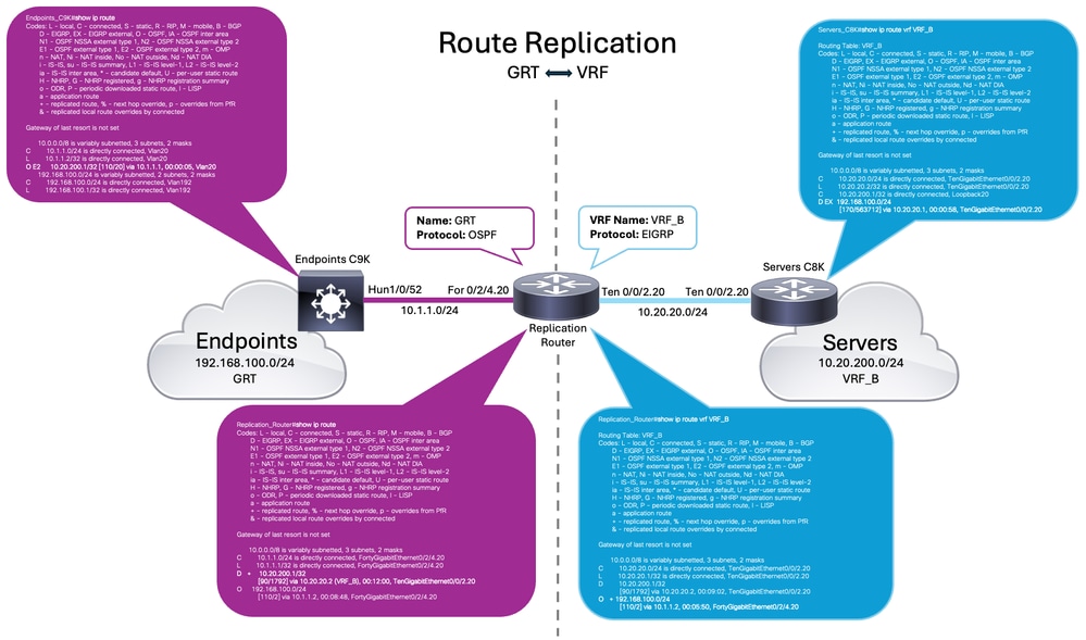 Route Replication Topology - Scenario 2 (GRT to VRF)
 Feedback