Introduction
This document describes how to use BGP Community Values to control the routing policy in upstream provider networks.
Prerequisites
Requirements
This document requires an understanding of the Border Gateway Protocol (BGP) routing protocol and its operation.
Components Used
This document is not restricted to specific software and hardware versions. However, the information in this document is based on this software version:
The information in this document was created from the devices in a specific lab environment. All of the devices used in this document started with a cleared (default) configuration. If your network is live, ensure that you understand the potential impact of any command.
Background Information
While communities themselves do not alter the BGP Best Path process, communities can be used as flags in order to mark a set of routes. Upstream service provider routers can then use these flags to apply specific routing polices (for example, the local preference) within their network.
Providers map between your configurable community values and the corresponding local preference values within the provider network. You can have specific policies that require the modification of LOCAL_PREF in the provider network set and the corresponding community values in their routing updates.
A community is a group of prefixes that share some common property and can be configured with the BGP community attribute. The BGP community attribute is an optional transitive attribute of variable length. The attribute consists of a set of four octet values that specify a community. The community attribute values are encoded with an Autonomous System (AS) number in the first two octets, with the other two octets defined by the AS. A prefix can have more than one community attribute. A BGP speaker that sees multiple community attributes in a prefix can act based on one, some or all of the attributes. A router has the option to add or modify a community attribute before the router passes the attribute on to other peers. In order to learn more about the community attribute, refer to BGP Case Studies.
The local preference attribute is an indication to the AS which path is preferred to reach a certain network. When there are multiple paths to the same destination, the path with the higher preference is chosen (the default value of the local preference attribute is 100). For more information, refer to Case Studies.
Conventions
For more information on document conventions, refer to the Cisco Technical Tips Conventions.
Configure and Control the Routing Policy
Note: To find additional information on the commands used in this document, use the Command Lookup Tool.
For simplification, the community attribute and local preference attribute mapping is assumed to be established between the upstream service provider (AS 100) and your device (AS 30).
|
Local Preference
|
Community Values
|
|
130
|
100:300
|
|
125
|
100:250
|
If the prefixes are announced with a community attribute equal to 100:300, then the upstream service provider sets the local preference of those routes to 130 and 125 if the community attribute equals 100:250.
This gives you control over the routing policy within the service provider network if you change the community values of the prefixes announced to the service provider.
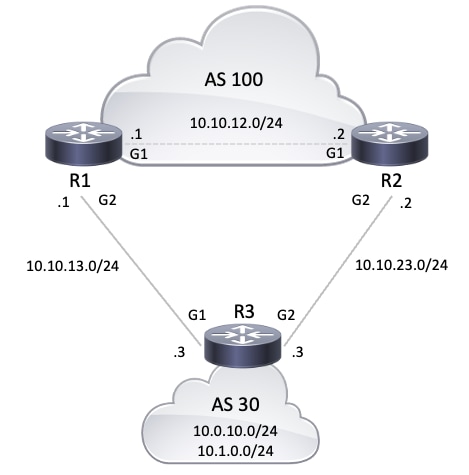
In the network diagram , the AS 30 wants to use this routing policy with the community attributes.
-
The traffic inbound from AS 100 destined to network 10.0.10.0/24 travels through the R1-R3 link. If the R1-R3 link fails, all traffic travels through R2-R3.
-
The traffic inbound from AS 100 destined to network 10.1.0.0/24 travels through the R2-R3 link. If the R2-R3 link fails, all traffic travels through R1-R3.
To achieve this routing policy, R3 announces its prefixes in this way:
To R1:
- 10.0.10.0/24 with a community attribute 100:300
- 10.1.0.0/24 with a community attribute 100:250
To R2:
Once BGP neighbors R1 and R2 receive the prefixes from R3, R1 and R2 apply the configured policy based on mapping between the community and local preference attributes (shown in the previous table), and thus achieve the routing policy dictated by you (the AS 30). R1 installs the prefixes in the BGP table.
R2 installs the prefix in its BGP table:
Since a higher local preference is preferred in the BGP path selection criteria, the path with a local preference of 130 (130 is greater than 125) is selected as the best path within AS 100, and is installed in the IP routing table of R1 and R2. For more information on BGP path selection criteria, refer to BGP Best Path Selection Algorithm.
Network Diagram
Configurations
This document uses these configurations:
| R3 Configuration |
hostname R3
!
interface Loopback0
 ip address 10.0.10.1 255.255.255.0
!
interface Loopback1
 ip address 10.1.0.1 255.255.255.0
!
interface GigabitEthernet1
 ip address 10.10.13.3 255.255.255.0

!--- Interface connected to R1
!
interface GigabitEthernet2
 ip address 10.10.23.3 255.255.255.0

!--- Interface connected to R2
!
router bgp 30
 bgp router-id interface Loopback0
 network 10.0.10.0 mask 255.255.255.0
 network 10.1.0.0 mask 255.255.255.0

!--- Network commands announce prefix 10.0.10.0/24 and 10.1.0.0/24.

 neighbor 10.10.13.1 remote-as 100

!--- Establishes peering with R1

 neighbor 10.10.13.1 send-community

!--- Without this command, the community attributes are not sent to the neighbor

 neighbor 10.10.13.1 route-map Peer-R1 out

!--- Configures outbound policy as defined by route-map "Peer-R1" when peering with R1

 neighbor 10.10.23.2 remote-as 100

!--- Establishes peering with R2

 neighbor 10.10.23.2 send-community

!--- Configures to send community attribute to R2

 neighbor 10.10.23.2 route-map Peer-R2 out

!--- Configures outbound policy as defined by
!--- route-map "Peer-R2" when peering with R2.

!
ip bgp-community new-format

!--- Allows you to configure the BGP community
!--- attribute in AA:NN format.

!
access-list 101 permit ip 10.0.10.0 0.0.0.255 any
access-list 102 permit ip 10.1.0.0 0.0.0.255 any
!
route-map Peer-R1 permit 10
 match ip address 101
 set community 100:300

!--- Sets community 100:300 for routes matching access-list 101

!
route-map Peer-R1 permit 20
 match ip address 102
 set community 100:250

!--- Sets community 100:250 for routes matching access-list 102

!
route-map Peer-R2 permit 10
 match ip address 101
 set community 100:250

!--- Sets community 100:250 for routes matching access-list 101

!
route-map Peer-R2 permit 20
 match ip address 102
 set community 100:300

!--- Sets community 100:300 for routes matching access-list 102

!
end
|
| R1 Configuration |
hostname R1
!
interface Loopback0
 ip address 10.200.200.1 255.255.255.0
!
interface GigabitEthernet1
 ip address 10.10.12.1 255.255.255.0

!--- Connected to R2
!
interface GigabitEthernet2
 ip address 10.10.13.1 255.255.255.0

!--- Connected to R3

!
router bgp 100
 bgp log-neighbor-changes
 neighbor 10.10.12.2 remote-as 100

!--- Establishes peering with R2

 neighbor 10.10.12.2 next-hop-self
 neighbor 10.10.13.3 remote-as 30

!--- Establishes peering with R3

 neighbor 10.10.13.3 route-map Peer-R3 in

!--- Configures the inbound policy as defined by route-map "Peer-R3" when peering with R3.

 no auto-summary
!
ip bgp-community new-format

!--- Allows you to configure the BGP community attribute in AA:NN format.

ip community-list 1 permit 100:300
ip community-list 2 permit 100:250

!--- Defines community list 1 and 2.

!
route-map Peer-R3 permit 10
 match community 1
 set local-preference 130

!--- Sets local preference 130 for all routes matching community list 1.

!
route-map Peer-R3 permit 20
 match community 2
 set local-preference 125

!--- Sets local preference 125 for all routes matching community list 2.

!
route-map Peer-R3 permit 30

!--- Without this permit 30 statement, updates that do not match the permit 10 or permit 20 statements are dropped.

!
end
|
| R2 Configuration |
hostname R2
!
interface Loopback0
ip address 192.168.50.1 255.255.255.0
!
interface GigabitEthernet1
 ip address 10.10.12.2 255.255.255.0

!--- Connected to R1

!
interface GigabitEthernet2
 ip address 10.10.23.2 255.255.255.0

!--- Connected to R3
!
router bgp 100
 bgp log-neighbor-changes
 neighbor 10.10.12.1 remote-as 100

!--- Establishes iBGP peering with R1

 neighbor 10.10.12.1 next-hop-self
 neighbor 10.10.23.3 remote-as 30

!--- Establishes peering with R3

 neighbor 10.10.23.3 route-map Peer-R3 in

!--- Configures inbound policy as defined by route-map "Peer-R3" when peering with R3.

!
ip bgp-community new-format

!--- Allows you to configure the BGP community attribute in AA:NN format.

!
ip community-list 1 permit 100:300
ip community-list 2 permit 100:250

!--- Defines community list 1 and 2.

!
route-map Peer-R3 permit 10
 match community 1
 set local-preference 130

!--- Sets local preference 130 for all routes matching community list 1.

!
route-map Peer-R3 permit 20
 match community 2
 set local-preference 125

!--- Sets local preference 125 for all routes matching community list 2.

!
route-map Peer-R3 permit 30

!--- Without this permit 30 statement, updates that do not match the permit 10 or permit 20 statements are dropped.

!
end
|
Verification
R1 receives prefixes 10.0.10.0/24 and 10.1.0.0/24 with communities 100:300 and 100:250, as shown in the next show ip bgp command output result.
Note: Once these routes are installed into the BGP table based on the configured policy, prefixes with community 100:300 are assigned local preference 130 and prefixes with community 100:250 are assigned local preference 125.
R1#show ip bgp 10.0.10.0
BGP routing table entry for 10.0.10.0/24, version 19
Paths: (1 available, best #1, table default)
  Advertised to update-groups:
     4
  Refresh Epoch 1
  30
    10.10.13.3 from 10.10.13.3 (10.0.10.1)
      Origin IGP, metric 0, localpref 130, valid, external, best
      Community: 100:300
      rx pathid: 0, tx pathid: 0x0
      Updated on Oct 31 2025 16:47:42 UTC

!--- Prefix 10.0.10.0/24 with community 100:300 received from 10.10.13.3 (R3) is assigned local preference 130.
R1#show ip bgp 10.1.0.0
BGP routing table entry for 10.1.0.0/24, version 20
Paths: (2 available, best #1, table default)
  Advertised to update-groups:
     6
  Refresh Epoch 1
  30
    10.10.12.2 from 10.10.12.2 (192.168.50.1)
      Origin IGP, metric 0, localpref 130, valid, internal, best
      rx pathid: 0, tx pathid: 0x0
      Updated on Oct 31 2025 16:47:42 UTC
  Refresh Epoch 1
  30
    10.10.13.3 from 10.10.13.3 (10.0.10.1)
      Origin IGP, metric 0, localpref 125, valid, external
      Community: 100:250
      rx pathid: 0, tx pathid: 0
      Updated on Oct 31 2025 16:47:42 UTC

!--- Received prefix 10.1.0.0/24 over iBGP from 10.10.12.2 (R2) with local preference 130
!--- Prefix 10.1.0.0/24 with community 100:250 received from 10.10.13.3 (R3) is assigned local preference 125.
R1#show ip bgp
BGP table version is 20, local router ID is 10.200.200.1
Status codes: s suppressed, d damped, h history, * valid, > best, i - internal,
              r RIB-failure, S Stale, m multipath, b backup-path, f RT-Filter,
              x best-external, a additional-path, c RIB-compressed,
              t secondary path, L long-lived-stale,
Origin codes: i - IGP, e - EGP, ? - incomplete
RPKI validation codes: V valid, I invalid, N Not found

     Network          Next Hop            Metric LocPrf Weight Path
 *>   10.0.10.0/24     10.10.13.3               0    130      0 30 i
 *>i  10.1.0.0/24      10.10.12.2               0    130      0 30 i
 *                     10.10.13.3               0    125      0 30 i

R1#show ip bgp summary
BGP router identifier 10.200.200.1, local AS number 100
BGP table version is 20, main routing table version 20
2 network entries using 496 bytes of memory
3 path entries using 408 bytes of memory
5/2 BGP path/bestpath attribute entries using 1440 bytes of memory
1 BGP AS-PATH entries using 24 bytes of memory
2 BGP community entries using 48 bytes of memory
0 BGP route-map cache entries using 0 bytes of memory
0 BGP filter-list cache entries using 0 bytes of memory
BGP using 2416 total bytes of memory
BGP activity 4/2 prefixes, 15/12 paths, scan interval 60 secs
2 networks peaked at 15:24:53 Oct 31 2025 UTC (04:38:04.419 ago)

Neighbor        V           AS MsgRcvd MsgSent   TblVer  InQ OutQ Up/Down  State/PfxRcd
10.10.12.2      4          100     242     243       20    0    0 03:31:31        1
10.10.13.3      4           30     219     219       20    0    0 03:16:06        2
The show ip bgp command on R1 confirms that the best path selected on R1 are with local preference(LoclPrf) = 130. Similarly, R2 receives prefixes 10.0.10.0/24 and 10.1.0.0/24 with communities 100:250 and 100:300, as shown in bold in this show ip bgp command output:
Note: Once these routes are installed into the BGP table, based on the configured policy, prefixes with community 100:300 are assigned local preference 130 and prefixes with community 100:250 are assigned local preference 125.
R2#show ip bgp 10.0.10.0
BGP routing table entry for 10.0.10.0/24, version 13
Paths: (2 available, best #1, table default)
  Advertised to update-groups:
     6
  Refresh Epoch 1
  30
    10.10.12.1 from 10.10.12.1 (10.200.200.1)
      Origin IGP, metric 0, localpref 130, valid, internal, best
      rx pathid: 0, tx pathid: 0x0
      Updated on Oct 31 2025 16:47:42 UTC
  Refresh Epoch 1
  30
    10.10.23.3 from 10.10.23.3 (10.0.10.1)
      Origin IGP, metric 0, localpref 125, valid, external
      Community: 100:250
      rx pathid: 0, tx pathid: 0
      Updated on Oct 31 2025 16:47:42 UTC

!--- Prefix 10.0.10.0/24 with community 100:250 received from 10.10.23.3 (R3) is assigned local preference 125
!--- Received prefix 10.0.10.0/24 over iBGP from 10.10.12.1 (R1) with local preference 130
R2#show ip bgp 10.1.0.0
BGP routing table entry for 10.1.0.0/24, version 11
Paths: (1 available, best #1, table default)
  Advertised to update-groups:
     5
  Refresh Epoch 1
  30
    10.10.23.3 from 10.10.23.3 (10.0.10.1)
      Origin IGP, metric 0, localpref 130, valid, external, best
      Community: 100:300
      rx pathid: 0, tx pathid: 0x0
      Updated on Oct 31 2025 16:47:42 UTC

!--- Prefix 10.1.0.0/24 with community 100:300 received from 10.10.23.3 (R3) is assigned local preference 130.
R2#show ip bgp
BGP table version is 13, local router ID is 192.168.50.1
Status codes: s suppressed, d damped, h history, * valid, > best, i - internal,
              r RIB-failure, S Stale, m multipath, b backup-path, f RT-Filter,
              x best-external, a additional-path, c RIB-compressed,
              t secondary path, L long-lived-stale,
Origin codes: i - IGP, e - EGP, ? - incomplete
RPKI validation codes: V valid, I invalid, N Not found

     Network          Next Hop            Metric LocPrf Weight Path
 *>i  10.0.10.0/24     10.10.12.1               0    130      0 30 i
 *                     10.10.23.3               0    125      0 30 i
 *>   10.1.0.0/24      10.10.23.3               0    130      0 30 i

R2#show ip bgp summary
BGP router identifier 192.168.50.1, local AS number 100
BGP table version is 13, main routing table version 13
2 network entries using 496 bytes of memory
3 path entries using 408 bytes of memory
5/2 BGP path/bestpath attribute entries using 1440 bytes of memory
1 BGP AS-PATH entries using 24 bytes of memory
2 BGP community entries using 48 bytes of memory
0 BGP route-map cache entries using 0 bytes of memory
0 BGP filter-list cache entries using 0 bytes of memory
BGP using 2416 total bytes of memory
BGP activity 6/4 prefixes, 18/15 paths, scan interval 60 secs
2 networks peaked at 16:18:51 Oct 31 2025 UTC (03:55:29.816 ago)

Neighbor        V           AS MsgRcvd MsgSent   TblVer  InQ OutQ Up/Down  State/PfxRcd
10.10.12.1      4          100     255     254       13    0    0 03:42:55        1
10.10.23.3      4           30     233     232       13    0    0 03:27:29        2
This show ip bgp command output on R2 confirms the best path selected on R2 are with local preference(loclPrf) = 130. The IP route to prefix 10.0.10.0/24 prefers the R1-R3 link to exit out of AS 100 towards AS 30. The show ip route command on R1 and R2 confirms this preference.
R1#show ip route 10.0.10.0
Routing entry for 10.0.10.0/24
  Known via "bgp 100", distance 20, metric 0
  Tag 30, type external
  Last update from 10.10.13.3 03:28:31 ago
  Routing Descriptor Blocks:
  * 10.10.13.3, from 10.10.13.3, 03:28:31 ago
      opaque_ptr 0x7F19642ACC28
      Route metric is 0, traffic share count is 1
      AS Hops 1
      Route tag 30
      MPLS label: none

!--- On R1, the IP route to prefix 10.0.10.0/24 points to next hop 10.10.13.3 which is R3 interface on the R1-R3 link.
R2#show ip route 10.0.10.0
Routing entry for 10.0.10.0/24
  Known via "bgp 100", distance 200, metric 0
  Tag 30, type internal
  Last update from 10.10.12.1 03:29:07 ago
  Routing Descriptor Blocks:
  * 10.10.12.1, from 10.10.12.1, 03:29:07 ago
      opaque_ptr 0x7F14CD5E7D00
      Route metric is 0, traffic share count is 1
      AS Hops 1
      Route tag 30
      MPLS label: none

!--- On R2, IP route to prefix 10.0.10.0/24 points to next hop R1 (10.10.12.1) on its iBGP link
!--- Thus traffic to network 10.0.10.0/24 from R2 exits through R2-R1 and then R1-R3 link from AS 100 towards AS 30
The IP route to prefix 10.1.0.0/24 prefers R2-R3 link to exit out of AS 100 towards AS 30. The show ip route command on R1 and R2 confirms this preference.
R2#show ip route 10.1.0.0
Routing entry for 10.1.0.0/24
  Known via "bgp 100", distance 20, metric 0
  Tag 30, type external
  Last update from 10.10.23.3 03:31:41 ago
  Routing Descriptor Blocks:
  * 10.10.23.3, from 10.10.23.3, 03:31:41 ago
      opaque_ptr 0x7F14CD5E7A90
      Route metric is 0, traffic share count is 1
      AS Hops 1
      Route tag 30
      MPLS label: none

!--- On R2, IP route to prefix 10.1.0.0/24 points to next hop 10.10.23.3 which is R3 interface on R2-R3 link.
R1#show ip route 10.1.0.0
Routing entry for 10.1.0.0/24
  Known via "bgp 100", distance 200, metric 0
  Tag 30, type internal
  Last update from 10.10.12.2 03:33:03 ago
  Routing Descriptor Blocks:
  * 10.10.12.2, from 10.10.12.2, 03:33:03 ago
      opaque_ptr 0x7F19642AC748
      Route metric is 0, traffic share count is 1
      AS Hops 1
      Route tag 30
      MPLS label: none

!--- On R1, IP route to prefix 10.1.0.0/24 points to next hop R2 (10.10.12.2) on its iBGP link.
!--- Thus traffic to network 10.1.0.0/24 from R1 exits through R1-R2 and then R2-R3 link from AS 100 towards AS 30.
If one link fails, for example the R1-R3 link, all traffic must track the R2-R3 link. You can simulate this traffic if you shut down the link between R1-R3.
R1#configure terminal
Enter configuration commands, one per line.  End with CNTL/Z.
R1(config)#interface gigabitEthernet 2
R1(config-if)#shutdown
R1(config-if)#
*Oct 31 21:26:31.423: %BGP-5-NBR_RESET: Neighbor 10.10.13.3 reset (Interface flap)
*Oct 31 21:26:31.461: %BGP-5-ADJCHANGE: neighbor 10.10.13.3 Down Interface flap
*Oct 31 21:26:31.461: %BGP_SESSION-5-ADJCHANGE: neighbor 10.10.13.3 IPv4 Unicast topology base removed from session  Interface flap
*Oct 31 21:26:33.373: %LINK-5-CHANGED: Interface GigabitEthernet2, changed state to administratively down
*Oct 31 21:26:34.378: %LINEPROTO-5-UPDOWN: Line protocol on Interface GigabitEthernet2, changed state to down
Notice the IP routing table for prefix 10.0.10.0/24 and 10.1.0.0/24 on R1 and R2. Use R2-R3 link in order to exit out of AS 100.
R1#show ip route 10.0.10.0
Routing entry for 10.0.10.0/24
  Known via "bgp 100", distance 200, metric 0
  Tag 30, type internal
  Last update from 10.10.12.2 00:01:17 ago
  Routing Descriptor Blocks:
  * 10.10.12.2, from 10.10.12.2, 00:01:17 ago
      opaque_ptr 0x7F19642AC880
      Route metric is 0, traffic share count is 1
      AS Hops 1
      Route tag 30
      MPLS label: none
R1#show ip route 10.1.0.0
Routing entry for 10.1.0.0/24
  Known via "bgp 100", distance 200, metric 0
  Tag 30, type internal
  Last update from 10.10.12.2 04:41:06 ago
  Routing Descriptor Blocks:
  * 10.10.12.2, from 10.10.12.2, 04:41:06 ago
      opaque_ptr 0x7F19642AC748
      Route metric is 0, traffic share count is 1
      AS Hops 1
      Route tag 30
      MPLS label: none
The previous show command output shows that the route to prefixes10.0.10.0/24 and 10.1.0.0/24 points to the next hop 10.10.12.2, (R2), which is expected. Now, take a look at the IP routing table on R2 to check next-hop of prefix 10.0.10.0/24 and 10.1.0.0/24. The next hop must be R3 for the configured policy in order to work successfully.
R2#show ip route 10.0.10.0
Routing entry for 10.0.10.0/24
  Known via "bgp 100", distance 20, metric 0
  Tag 30, type external
  Last update from 10.10.23.3 00:04:34 ago
  Routing Descriptor Blocks:
  * 10.10.23.3, from 10.10.23.3, 00:04:34 ago
      opaque_ptr 0x7F14CD5E7820
      Route metric is 0, traffic share count is 1
      AS Hops 1
      Route tag 30
      MPLS label: none
R2#show ip route 10.1.0.0
Routing entry for 10.1.0.0/24
  Known via "bgp 100", distance 20, metric 0
  Tag 30, type external
  Last update from 10.10.23.3 04:44:05 ago
  Routing Descriptor Blocks:
  * 10.10.23.3, from 10.10.23.3, 04:44:05 ago
      opaque_ptr 0x7F14CD5E7A90
      Route metric is 0, traffic share count is 1
      AS Hops 1
      Route tag 30
      MPLS label: none
The next hop 10.10.23.3 is R3 interface GigabitEthernet2 on the R2-R3 link. This confirms the configured policy works as expected.
Related Information
 Feedback