Configure a Secure eBGP Session with an IPsec VTI
Available Languages
Download Options
Bias-Free Language
The documentation set for this product strives to use bias-free language. For the purposes of this documentation set, bias-free is defined as language that does not imply discrimination based on age, disability, gender, racial identity, ethnic identity, sexual orientation, socioeconomic status, and intersectionality. Exceptions may be present in the documentation due to language that is hardcoded in the user interfaces of the product software, language used based on RFP documentation, or language that is used by a referenced third-party product. Learn more about how Cisco is using Inclusive Language.
Contents
Introduction
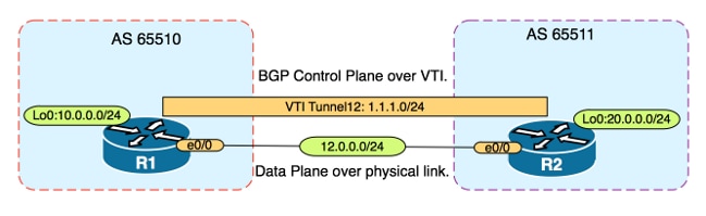
This document describes how to secure an external Border Gateway Protocol (eBGP) neighbor relationship with the use of an IPsec Virtual Tunnel Interface (VTI) along with the physical interfaces (non-tunnel) for the data plane traffic. Benefits of this configuration include:
- Complete privacy of the BGP neighbor session with data confidentiality, anti-replay, authenticity, and integrity.
- Data plane traffic is not constrained to the Maximum Transmission Unit (MTU) overhead of the tunnel interface. Customers can send standard MTU packets (1500 bytes) without performance implications or fragmentation.
- Less overhead on the end point routers since Security Policy Index (SPI) encrypting/decrypting is limited to BGP control plane traffic.
The benefit of this configuration is that the data plane is not constrained to the limitation of the tunneled interface. By design, the data plane traffic is not IPsec secured.
Prerequisites
Requirements
Cisco recommends you have knowledge of these topics:
- eBGP configuration and verification fundamentals
- BGP Policy Accounting (PA) manipulation using a route-map
- Basic Internet Security Association and Key Management Protocol (ISAKMP) and IPsec policy features
Components Used
The information in this document is based on Cisco IOS® Software Release 15.3(1.3)T but other supported versions work. Since IPsec configuration is a cryptographic feature, ensure your version of code contains this feature set.
The information in this document was created from the devices in a specific lab environment. All of the devices used in this document started with a cleared (default) configuration. If your network is live, make sure that you understand the potential impact of any command.
Caution: The configuration example in this document uses modest cipher algorithms that might or might not be suited for your environment. See the Next Generation Encryption White Paper for a discussion of the relative security of various cipher suites and key sizes.
Configure
Note: Use the Command Lookup Tool (registered customers only) in order to obtain more information on the commands used in this section.
Network Diagram
Configurations
Complete these steps:
- Configure Internet Key Exchange (IKE) phase 1 parameters on R1 and R2 with the pre-shared key on R1:
Note: Never use DH group numbers 1, 2 or 5 since they are considered inferior. If possible use a DH group with Elliptic Curve Cryptopgraphy (ECC) such as groups 19, 20 or 24. Advanced Encryption Standard (AES) and Secure Hash Algorithm 256 (SHA256) should be considered superior to Data Encryption Standard (DES)/3DES and Message Digest 5 (MD5)/SHA1 respectively. Never use the password "cisco" in a production environment.
R1 Configuration
R1(config)#crypto isakmp policy 1
 R1(config-isakmp)#encr aes
R1(config-isakmp)#hash sha256
R1(config-isakmp)#authentication pre-share
 R1(config-isakmp)#group 19
R1(config-isakmp)exit


R1(config)#crypto isakmp key CISCO address 12.0.0.2
R2 Configuration
R2(config)#crypto isakmp policy 1
R2(config-isakmp)#encr aes
R2(config-isakmp)#hash sha256
R2(config-isakmp)#authentication pre-share
R2(config-isakmp)#group 19


R2(config-isakmp)exit

R2(config)#crypto isakmp key CISCO address 12.0.0.1 - Configure level 6 password encryption for the pre-shared key in NVRAM on R1 and R2. This reduces the likelihood of the pre-shared key stored in plain text from being read if a router is compromised:
R1(config)#key config-key password-encrypt CISCOCISCO

R1(config)#password encryption aes

R2(config)#key config-key password-encrypt CISCOCISCO

R2(config)#password encryption aesNote: Once the level 6 password encryption is enabled, the active configuration no longer shows the plain text version of the pre-shared key:
!
R1#show run | include key
crypto isakmp key 6 \Nd`]dcCW\E`^WEObUKRGKIGadiAAB address 12.0.0.2

! - Configure the IKE phase 2 parameters on R1 and R2:
R1 Configuration
R1(config)#crypto ipsec transform-set TRANSFORM-SET esp-aes 256 esp-sha256 ah-sha256-hmac

R1(config)#crypto ipsec profile PROFILE

R1(ipsec-profile)#set transform-set TRANSFORM-SET
R1(ipsec-profile)#set pfs group19
R2 Configuration
R2(config)#crypto ipsec transform-set TRANSFORM-SET esp-aes 256 esp-sha256 ah-sha256-hmac

R2(config)#crypto ipsec profile PROFILE

R2(ipsec-profile)#set transform-set TRANSFORM-SET

R2(ipsec-profile)#set pfs group19Note: Setting Perfect Forward Secrecy (PFS) is optional but improves VPN strength since it forces a new symmetric key generation in the IKE phase 2 SA establishment.
- Configure the tunnel interfaces on R1 and R2 and secure with the IPsec profile:
R1 Configuration
R1(config)#interface tunnel 12

R1(config-if)#ip address 1.1.1.1 255.255.255.0

R1(config-if)#tunnel source Ethernet0/0

R1(config-if)#tunnel mode ipsec ipv4

R1(config-if)#tunnel destination 12.0.0.2

R1(config-if)#tunnel protection ipsec profile PROFILE
R2 Configuration
R2(config)#interface tunnel 12

R2(config-if)#ip address 1.1.1.2 255.255.255.0

R2(config-if)#tunnel source Ethernet0/0

R2(config-if)#tunnel mode ipsec ipv4

R2(config-if)#tunnel destination 12.0.0.1

R2(config-if)#tunnel protection ipsec profile PROFILE - Configure BGP on R1 and R2 and advertise the loopback0 networks into BGP:
R1 Configuraton
R1(config)#router bgp 65510

R1(config-router)#neighbor 1.1.1.2 remote-as 65511

R1(config-router)#network 10.0.0.0 mask 255.255.255.0
R2 Configuration
R2(config)#router bgp 65511

R2(config-router)#neighbor 1.1.1.1 remote-as 65510

R2(config-router)#network 20.0.0.0 mask 255.255.255.0 - Configure a route-map on R1 and R2 in order to manually change the next hop IP address so that it points to the physical interface and not the tunnel. You must apply this route-map on the inbound direction.
R1 Configuration
R1(config)ip prefix-list R2-NETS seq 5 permit 20.0.0.0/24

R1(config)#route-map CHANGE-NEXT-HOP permit 10

R1(config-route-map)#match ip address prefix-list R2-NETS

R1(config-route-map)#set ip next-hop 12.0.0.2

R1(config-route-map)#end

R1(config)#router bgp 65510

R1(config-router)#neighbor 1.1.1.2 route-map CHANGE-NEXT-HOP in

R1(config-router)#do clear ip bgp *

R1(config-router)#end
R2 Configuration
R2(config)#ip prefix-list R1-NETS seq 5 permit 10.0.0.0/24

R2(config)#route-map CHANGE-NEXT-HOP permit 10

R2(config-route-map)#match ip address prefix-list R1-NETS

R2(config-route-map)#set ip next-hop 12.0.0.1

R2(config-route-map)#end

R2(config)#router bgp 65511

R2(config-router)#neighbor 1.1.1.1 route-map CHANGE-NEXT-HOP in

R2(config-router)#do clear ip bgp *

R2(config-router)#end
Verify
Use this section to confirm that your configuration works properly.
The Output Interpreter Tool (registered customers only) supports certain show commands. Use the Output Interpreter Tool in order to view an analysis of show command output.
Verify that both IKE phase 1 and IKE phase 2 have completed. The line protocol on the Virtual Tunnel Interface (VTI) does not change to "up" until IKE phase 2 has completed:
R1#show crypto isakmp sa
IPv4 Crypto ISAKMP SA
dst src state conn-id status
12.0.0.1 12.0.0.2 QM_IDLE 1002 ACTIVE
12.0.0.2 12.0.0.1 QM_IDLE 1001 ACTIVE

R1#show crypto ipsec sa | inc encaps|decaps
#pkts encaps: 88, #pkts encrypt: 88, #pkts digest: 88
 #pkts decaps: 90, #pkts decrypt: 90, #pkts verify: 90
Note that prior to the application of the route-map, the next hop IP address points to the BGP neighbor IP address which is the tunnel interface:
R1#show ip bgp
BGP table version is 2, local router ID is 10.0.0.1
Status codes: s suppressed, d damped, h history, * valid, > best, i - internal,
 r RIB-failure, S Stale, m multipath, b backup-path, f RT-Filter,
 x best-external, a additional-path, c RIB-compressed,
Origin codes: i - IGP, e - EGP, ? - incomplete
RPKI validation codes: V valid, I invalid, N Not found

Network Next Hop Metric LocPrf Weight Path
 *> 20.0.0.0/24 1.1.1.2 0 0 65511 i
When traffic uses the tunnel, the MTU is constrained to the tunnel MTU:
R1#ping 20.0.0.2 size 1500 df-bit
Type escape sequence to abort.
Sending 5, 1500-byte ICMP Echos to 20.0.0.2, timeout is 2 seconds:
Packet sent with the DF bit set

*May 6 08:42:07.311: ICMP: dst (20.0.0.2): frag. needed and DF set.
*May 6 08:42:09.312: ICMP: dst (20.0.0.2): frag. needed and DF set.
*May 6 08:42:11.316: ICMP: dst (20.0.0.2): frag. needed and DF set.
*May 6 08:42:13.319: ICMP: dst (20.0.0.2): frag. needed and DF set.
*May 6 08:42:15.320: ICMP: dst (20.0.0.2): frag. needed and DF set.
Success rate is 0 percent (0/5)

R1#show interfaces tunnel 12 | inc transport|line

Tunnel12 is up, line protocol is up
 Tunnel protocol/transport IPSEC/IP
 Tunnel transport MTU 1406 bytes <---

R1#ping 20.0.0.2 size 1406 df-bit
Type escape sequence to abort.
Sending 5, 1406-byte ICMP Echos to 20.0.0.2, timeout is 2 seconds:
Packet sent with the DF bit set
!!!!!
Success rate is 100 percent (5/5), round-trip min/avg/max = 5/5/6 ms
After applying the route-map, the IP address is changed to the physical interface of R2, not the tunnel:
R1#show ip bgp
BGP table version is 2, local router ID is 10.0.0.1
Status codes: s suppressed, d damped, h history, * valid, > best, i - internal,
 r RIB-failure, S Stale, m multipath, b backup-path, f RT-Filter,
 x best-external, a additional-path, c RIB-compressed,
Origin codes: i - IGP, e - EGP, ? - incomplete
RPKI validation codes: V valid, I invalid, N Not found

Network Next Hop Metric LocPrf Weight Path
 *> 20.0.0.0/24 12.0.0.2 0 0 65511 i
Change the data plane in order to use the physical next hop as opposed to the tunnel permits standard size MTU:
R1#ping 20.0.0.2 size 1500 df-bit
Type escape sequence to abort.
Sending 5, 1500-byte ICMP Echos to 20.0.0.2, timeout is 2 seconds:
Packet sent with the DF bit set
!!!!!
Success rate is 100 percent (5/5), round-trip min/avg/max = 4/4/5 ms
Troubleshoot
There is currently no specific troubleshooting information available for this configuration.
Contributed by Cisco Engineers
- Charles StizzaCisco TAC Engineer
 Feedback
Contact Cisco
- Open a Support Case

- (Requires a Cisco Service Contract)